1
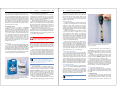
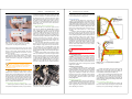
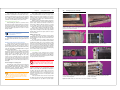
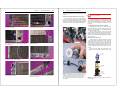
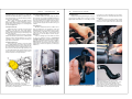
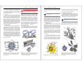
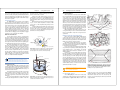
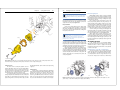
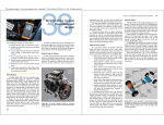
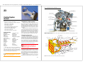
This sample chapter is for review purposes only. Copyright © The Goodheart-Willcox Co., Inc. All rights reserved.
454
Auto Diagnosis, Service, and Repair
23
Combustion chamber gases
4500°F (2484°C)
Piston crown center
550-575°F (288-302°C)
Cooling System
Service
After studying this chapter, you will be able to:
• Explain the role of antifreeze in an engine cooling system.
• Properly clean a cooling system.
• Detect leaks in a cooling system.
• Test a radiator pressure cap.
• List the safety rules dealing with cooling systems.
• Inspect and replace cooling system hoses.
• Inspect, replace, and adjust drive belts.
• Test and replace a thermostat.
• Inspect, repair, and replace a coolant pump.
Technical Terms
Depressurized
Overheated
Overheating protection
Antifreeze
Ethylene glycol
Propylene glycol
Long-life coolant
Organic acid technology
Hard water
Electrolysis
Hydrometer
Refractometer
Test strips
Alkalinity
Ph level
Bleeder valve
Reverse fill
Cooling system cleaner
Neutralizer
Reverse flushing
Pressure tester
Pressure cap
Electrochemical degradation
(ECD)
Belt tension
Electric fan assembly
Thermoswitch
Fluid clutch fan
Thermostat
Coolant pump
Impeller
Freeze plugs
Air-cooled engines
This chapter will cover the service requirements of
modern cooling systems, including diagnosis, coolant
replacement, system flushing, and repair operations. Although
most of the information in this chapter relates to liquid-cooled
systems, air-cooled systems are also discussed.
Caution: Use care when doing cooling system work
on vehicles equipped with airbags. Some sensors
are located near the radiator.
Top cylinder wall
200-700°F (93-371°C)
Exhaust valve stem
1175-1250°F (636-677°C)
Top piston ring
300-500°F (149-260°C)
Exhaust valve head
1200-1350°F (649-732°C)
The Need for a Cooling System
Automobile engines generate a large amount of heat.
About one-third of the heat energy developed by the fuel
burning in the cylinders is converted into power to drive the
automobile. Another third is wasted and goes out the exhaust.
The remaining third is absorbed by the metal of the engine
and must be disposed of by the cooling system to prevent
overheating.
Figure 23-1 shows the approximate temperatures of the
various engine parts during operation. Properly designed and
maintained automobile cooling systems are good at keeping
these temperatures within the normal range. The failure or
malfunction of one or more cooling system components,
however, can lead to serious overheating. Under certain conditions, cooling system problems can also cause overcooling.
Bottom cylinder wall
up to 300°F (149°C)
Combustion chamber wall
400-500°F (204-260°C)
Piston pin
250-450°F (121-232°C)
Connecting rod bearings
200-400°F (93-204°C)
Figure 23-1. Approximate temperatures of various engine components and areas. Temperatures vary depending upon engine
design and application. (Saab)
Cooling System Service
Thermostat housing
Modern cooling systems are relatively trouble free.
However, they can develop problems, especially if they are
neglected. Routine checks and periodic coolant replacement
will usually reveal cooling system problems before they reach
the serious stage. It is important to become familiar with problems associated with the cooling system, Figure 23-2.You
must know which units are responsible for specific problems,
how they can be checked, and if faulty, how they are repaired.
Thermostat
Heater control valve
Pressure cap
Radiator
Hose
clamp
Upper
hose
Heater
supply
Heater return hose
Dealing with an Overheated Engine
Warning: Hot coolant can scald or blind you. Before
performing any service on the cooling system,
make sure the cooling system has been
depressurized. The system is depressurized when all
pressure has been released.
If the engine is greatly overheated (indicated by steam
spurting from the overflow), shut it down at once. If an engine
is moderately overheated, however, it is best to run the
engine at high idle for a minute or two before shutting it down.
Flow of the coolant helps to carry excess heat from the cylinders and valves, and there is less possibility of cylinder distortion and warped valves.
Never pour cold water into the radiator of an overheated
engine. Once the engine is shut down, open the hood and use
453
Overflow
tube
Core plug
Drain plug
Overflow
recovery tank
Coolant circulating
through cylinder
block and head
Automatic transmission
fluid cooler pipes
Water pump
Lower hose
Fan
Figure 23-2. Potential cooling and/or heating system problem areas. (Gates)
Chapter 23
a shop fan to blow cool air through the radiator and across the
engine surface. Allow the engine to cool down until the coolant
is no longer boiling (at least thirty minutes). Slowly open the
radiator cap, then start the engine. While running the engine
at a fast idle, slowly add water to the radiator. The pump will
mix the hot coolant and the cold water. Run the engine until
the temperature is normal. If the engine begins to overheat
again, shut it off. Then, recheck the radiator coolant level. If the
coolant level is correct, find out what is causing the engine to
overheat and correct the problem.
Overheating Protection
On some newer cars, a special type of overheating
protection is used. If the engine begins to overheat, the
computer will shut down some cylinders by turning off the fuel
injectors to those cylinders. The usual procedure is to turn off
alternating cylinders in the firing order. If the firing order is
1, 3, 6, 2, 5, 4, for instance, the computer will shut down cylinders 1, 6, and 5. This allows the engine to operate as smoothly
as possible while the cylinders cool down. After they cool
down, their fuel injectors are turned back on, and the fuel
injectors for cylinders 3, 2, and 4 are turned off. The cycle
repeats as necessary. By causing the engine to run on alternating cylinders, this method ensures no one cylinder is
allowed to become too hot.
Antifreeze
In all areas where temperatures may drop below freezing
(32°F or 0°C), it is necessary to keep antifreeze, Figure 23-3,
in the cooling system to prevent engine damage. In addition,
an antifreeze and water mixture is better than plain water at
transferring heat in hot weather. Antifreeze contains rust inhibitors, which prevent damage to the engine, radiator, and heater
core, as well as small amounts of water-soluble oils, which lubricate the coolant pump seals and heater shutoff valves.
Cooling System Service
455
Ethylene and Propylene Glycol Antifreeze
In the past, many liquids were used as antifreeze,
including kerosene, denatured ethyl alcohol, and methanol
(wood alcohol). There are several compounds used to make
antifreeze solutions. The first is called ethylene glycol. This
antifreeze is sometimes called EG coolant.
Ethylene glycol will freeze at roughly 9°F (–13°C). When
ethylene glycol is mixed with water, which has a freezing point
of 32°F (0°C), the resulting mixture has a freezing point lower
than either liquid by itself. A half-and-half (50-50) mixture of
antifreeze and water has a freezing point of about –35°F
(–37°C). A mixture of 70% antifreeze and 30% water will not
freeze until the temperature reaches –67°F (–55°C).
Ethylene glycol is not a fire hazard, and it does not harm
paint finishes. It does not readily evaporate at normal system
temperatures, and it can be used with high-temperature thermostats. Additionally, it can be left in the cooling system for up
to a year without causing problems.
Warning: Ethylene glycol antifreeze is poisonous
and must not be taken internally. Keep antifreeze
away from children and animals. Never put beverages
or drinking water in empty antifreeze containers.
The second type of antifreeze compound is propylene
glycol or PG coolant. Propylene glycol coolants are nontoxic
and are considered to be “environmentally safe.” However,
since all used coolants contain some levels of heavy metals
from the cooling system, used antifreeze must be disposed of
properly.
A 50-50 mixture of propylene glycol antifreeze and water
will freeze at –26°F (–32°C). A 60-40 mixture will freeze at
–54°F (–48°C). Increasing the antifreeze concentration above
70%, however, will cause the mixture’s freezing point to rise.
Most manufacturers recommend a 50-50 mixture of water and
antifreeze. EG and PG coolants should not be mixed together.
Note: Dyes are used to give antifreeze its color. The
color of a coolant can vary (green, blue, red,
yellow, orange, or pink) and has no bearing on its
composition or service life. Check a service manual for the
proper type to use in a given application.
Long-life Coolants
Figure 23-3. Conventional and long-life antifreeze comes in
one gallon containers. Be sure you know which type is used in
a vehicle before adding. (Jack Klasey)
Some manufacturers use long-life coolant in the
cooling system. This coolant can be used for 100,000 miles
(160 000 km). Long-life coolant may be referred to as organic
acid technology (OAT) coolant. This coolant is made without
silicates and other minerals that cause cooling system
deposits. Since this coolant is made with ethylene glycol, it
has the same freezing and boiling points as a conventional
coolant. Do not mix this antifreeze with other types, since this
will reduce the long-life properties of the antifreeze.
Long-life coolants have approximately the same freeze
points as conventional ethylene glycol coolant. A 50-50 mixture
456
Auto Diagnosis, Service, and Repair
will protect the cooling system down to –34°F (–36°C). The
boiling point is raised about the same amount as with conventional coolant. Also, like regular coolants, mixtures greater
than 70% coolant are not recommended. Some long-life
coolants come prediluted 50-50 from the manufacturer, eliminating the need to add water.
Mixing Antifreeze
All vehicle manufacturers recommend keeping at least a
50-50 mixture of water and antifreeze in the cooling system at
all times. The correct amount of antifreeze to use is determined by the capacity of the cooling system. For example, a
20-quart cooling system should have 10 quarts of antifreeze
and 10 quarts of water. Never try to save money by adding just
enough antifreeze to get by.
Always use clean water to top off the antifreeze solution.
In most areas, tap water is acceptable for use in cooling
systems. However, the water supply in some localities has
high concentrations of lime, minerals, and acids. Water
containing these minerals is known as hard water. Hard water
can cause layers of chemicals to build up in the cooling
system, reducing the transfer of heat from the metal to the
coolant. If your area has this type of water, use another source
of water, such as bottled distilled water.
Modern engines and cooling systems contain cast iron,
aluminum, steel, brass, copper, and various types of solder.
These dissimilar metals can cause electrolysis (creation of
an electric current) in the system, with resulting damage to the
metals. An increasing cause of electrolysis is defective or
missing ground wires, as well as poorly grounded aftermarket
accessory systems. Electrolysis due to poor grounds can
destroy a radiator, heater core, or an entire engine.
Useful Life of Antifreeze
The cooling systems of most new cars are filled with a
mixture of antifreeze, rust inhibitors, pump lubricant, and clean
water. Unless excessive coolant is lost for some reason,
coolant can be left in the system for the time period recommended by the manufacturer. This time period for conventional
coolant is usually about 24 months. Long-life coolants can be
left in for a much longer period. It is suggested the recommendations of the manufacturer be followed regarding the type of
antifreeze and length of use. Failure to comply with the manufacturer’s recommendations may void the vehicle’s warranty.
Checking Antifreeze
To test the coolant protection level at operating temperature, use an antifreeze hydrometer, Figure 23-4. Most
antifreeze hydrometers have some form of temperature
correction, so they can be used with hot or cold coolant. Draw
the coolant in and out of the hydrometer several times to bring
hydrometer temperature up to coolant temperature. When
using the test unit, follow manufacturer’s instructions.
Note: A battery hydrometer cannot be used to
check antifreeze.
Figure 23-4. One type of antifreeze hydrometer being used to
check the concentration (percentage) of antifreeze in the
system. (Jack Klasey)
Another tool that can be used to check antifreeze is a
refractometer. To use a refractometer, take a small sample of
coolant from the radiator. Place a few drops on the refractometer lens. Look through the refractometer to get the freeze
point reading.
Some shops now use test strips to quickly check engine
coolant. Chemical test strips can check coolant for freeze
protection, as well as its alkalinity or pH level. However, most
test strips can only be used for conventional coolants.
To perform the test, remove one strip from the container.
Be sure to close the container, since the color chart is often on
the side. Dip the test strip in the engine coolant, making sure
both test spots are immersed. Remove the test strip and wait
approximately 30 seconds. Compare the two test sections to
the color chart that comes with the strips, Figure 23-5.
Cooling System Maintenance
Cooling system maintenance includes coolant replacement, locating leaks, and checking for proper fan operation.
If a cooling system is properly maintained, flushing is usually
not needed.
Coolant Replacement
To perform a simple coolant change, operate the engine
until the thermostat is open (the top radiator hose is hot). Shut
off the engine and place a drain pan under the petcock, then
open the petcock. Allow the coolant to drain into the pan.
Chapter 23
Cooling System Service
457
coolant level, keeping it to within about 3″ (76mm) of the filler
neck. On most vehicles, the coolant level will slowly rise until
the thermostat opens. The coolant may surge as the engine
warms up. When the thermostat opens, the level of coolant in
the radiator will drop suddenly. Add coolant to bring the
system up to its normal full level. Monitor the level for a few
more minutes to be sure all air has been removed. Then,
install the pressure cap.
A
B
Figure 23-5. Chemically coated test strips can be used to
check concentration as well as acidity or pH. A—Checking
concentration. B—Checking pH level. (Jack Klasey)
When coolant stops flowing from the petcock, the system
pressure has been removed. Remove the pressure cap and
allow the coolant to drain completely. Perform other service
operations as necessary. Allow the old coolant to cool, then
dispose of it properly.
Close the petcock. Using a coolant mixture of 50%
antifreeze and 50% water, refill the system. Do not completely
fill the radiator, since there must be room for the hot coolant to
expand. Then bleed the cooling system as explained in the
next section.
System with Filler Neck below Engine Block
When the filler neck is below the engine block, the
engine may be equipped with a bleeder valve. Locate the
valve on the engine—it is usually at or near the thermostat
housing, Figure 23-6. Open the bleeder valve and add
coolant to the radiator until it begins to flow from the valve.
Lightly close the bleeder valve. Start the engine, turn the
heater on full, and allow the engine to warm up. Monitor the
coolant level, keeping it to within about 3″ (76mm) of the filler
neck. Open the bleeder valve occasionally to allow air to
escape. When only coolant escapes from the bleeder valve,
top off the radiator and install the cap. Allow the engine to cool,
then recheck the level.
Some older vehicles with the filler neck below the engine
block do not have a bleeder valve. To bleed these vehicles,
begin by filling the cooling system to the top of the filler neck.
Some technicians choose to reverse fill the engine with
coolant to minimize the amount of trapped air in the water
jackets. This is done by disconnecting the upper radiator hose
from the radiator and adding coolant to the engine through the
upper hose.
Start the engine and turn the heater on full. As the engine
warms up, monitor both the coolant level and engine temperature. Do not allow the engine to overheat. If the engine begins
to overheat, shut it off and run a shop fan over the engine to
cool it down. Once the air bubble comes out of the engine, the
coolant level will drop significantly. When this occurs, fill the
radiator to the top of the filler neck and run the engine to
ensure the cooling system has been completely bled. It may
Caution: Do not install long-life coolant in a vehicle
that uses conventional coolant after replacing a
major cooling system part, such as a heater core,
water pump, or radiator. A possible loss in corrosion
protection may result.
Bleeding the Cooling System
Air pockets often form in the engine when the coolant is
drained. These air pockets are hard to remove on many
modern vehicles since the radiator filler neck is not the highest
point in the system. Since air is lighter than coolant, it rises to
the highest point in the engine. On older rear-wheel drive vehicles, the filler neck is above the engine block and air pockets
usually remove themselves from the system as the coolant
circulates. The following paragraphs explain bleeding procedures according to filler neck placement.
System with Filler Neck above Engine Block
Start the engine and allow it to warm up. Turn the heater
on full (mode and temperatures switches). Closely monitor the
Bleeder
valve
Figure 23-6. Newer engines have one or more bleeder valves
to help remove air from the cooling system.
458
Auto Diagnosis, Service, and Repair
be necessary, in some cases, to raise the front of the vehicle
to remove all the air from the cooling system.
Water hose
System Flushing
Mild rust and scale buildup in the cooling system can
usually be corrected by flushing the system with a chemical
cooling system cleaner. When the vehicle has an aluminum
engine, cylinder head, or radiator, you must use a cleaner that
is harmless to aluminum. Avoid splashing cleaner on the paint
finish. Carefully follow the instructions supplied by the manufacturer of the cleaning product. Some cleaners are of a onestep type, while others require two or more separate
operations.
To perform a simple flush, drain the old antifreeze solution from the system. Close all drains. Fill the system with
clean water, reinstall the radiator cap, and run the engine until
normal operating temperature is attained. Add cleaner to the
system and start the engine. Set the heater control to
maximum heat, allowing coolant and cleaner to circulate
through the heater lines and core. After allowing the cleaner to
circulate for the recommended period of time, stop the engine
and drain the system again. Remove radiator cap while
draining. Do not let the solution of water and cleaner boil. If the
vehicle is outside and the weather is very cold, be careful of
slush ice forming in the radiator.
Air hose
Flushing gun
Lead away hose
Clamp
A
Water hose
Air hose
Clamps
Thermostat removed
Warning: When coolant is hot, use extreme caution
while removing system pressure caps
Neutralizing and Flushing
If an acid-type cleaner is used, it must be neutralized. A
neutralizer reacts with cleaning chemical that is left in the
cooling system, transforming it into a harmless substance.
Failure to neutralize and flush properly may leave acids in the
system. These acids will attack the system and destroy the
protective properties of the inhibitors and the antifreeze. Pour
the neutralizer into the system, run the engine for the specified
length of time, and drain.
Heavy-Duty System Cleaning
Long periods of neglect often result in a cooling system
literally choked with rust and scale. This can often be detected
by feeling the radiator surface when the engine is moderately
warm. Cold spots on the radiator surface are evidence of
clogged tubes. Ultimately, the radiator tubes will become
blocked enough to cause the coolant in the system to boil. The
boiling action breaks loose large quantities of scale that may
plug the radiator completely. Correction requires reverse
flushing, Figure 23-7.
Radiator Reverse Flushing
Reverse flushing forces water through the radiator in a
direction opposite of normal flow, Figure 23-7A. This helps
to remove particles that are jammed into openings. Severe
radiator clogging may require removing the radiator from the
vehicle and boiling it in a hot tank.
Engine block
B
Figure 23-7. Reverse flushing procedures. A—Radiator.
B—Engine block.
To begin reverse flushing, remove the upper and lower
radiator hoses. Disconnect the heater hoses. Attach the
flushing gun to the lower radiator outlet and a lead-away hose
to the top radiator outlet. Replace the radiator cap.
Run a stream of water through the radiator and periodically release blasts of air to agitate and loosen particles so
they can be flushed out. Do not exceed an air pressure of
20 psi (138 kPa). Pressures higher than this may rupture the
radiator. Continue the flushing and air blasting until clear water
flows out of the radiator.
Reverse Flushing the Engine Block
Be sure to remove the thermostat before flushing the
block. Some vehicles require removing the coolant pump and
heater hoses, since pressure flushing can damage the seal.
Chapter 23
Attach the flushing gun to the top water outlet of the
block. Attach a lead-away hose to the bottom outlet, if necessary. Reverse-flush the block using the procedure described
for the radiator. See Figure 23-7B. After flushing, reattach all
hoses securely. Fill the system with water and add antifreeze
or inhibitor as needed. Finally, test the system for leaks.
Reverse Flushing the Heater Core
After determining the direction of coolant flow, remove
the heater hoses from the engine block. Be sure to remove the
heater shut-off valve (if used) from the system before beginning the flushing procedure. To reverse flush the heater core,
follow the procedures presented in the section on reverse
flushing a radiator.
Note: Some heater systems cannot be reverse
flushed. Check the manufacturer’s
recommendations.
After flushing, reconnect the heater hoses and reinstall
the heater shutoff valve. Refill the cooling system and test it
for leaks.
Finding Leaks in the Cooling System
Cooling system leaks can develop over time. They can
be caused by corrosion, vibration, or the gradual loosening of
system fittings. Sometimes, cleaning may open cracks or
other tiny openings that had been sealed with rust. Removing
of the rust allows leaking to start. Figure 23-8 shows typical
examples of radiator damage.
Coolant leakage can cause engine overheating and
damage to the pistons, valves, and cylinder head. If coolant
leaks into the cylinders, it may plug the rings and cause hard
starting, excessive oil consumption, piston corrosion, and
bearing failure. Combustion gas leakage into the cooling
system can cause overheating and severe cooling system
corrosion. Any time the cooling system loses water and an
obvious leak cannot be found, the system should be pressure
tested, Figure 23-9, or checked with special chemicals or a
black light.
Pressure Testing the Cooling System
Pressurizing the cooling system raises the boiling point
of the coolant mixture. This allows the engine to operate at
higher temperatures without causing the coolant to boil. Hotter
temperatures increase combustion efficiency, resulting in
more power, better mileage, and lower emissions.
Caution: Some of the newest systems use
pressures up to 25 psi (172 kPa). Special pressure
testers must be used on these systems. Do not
pressurize older systems past 20 psi (137 kPa). Higher
pressure could cause the radiator, heater core, or other
components to rupture.
Cooling System Service
459
Fill the radiator to within 1/2″ (12.7mm) of the filler neck.
Attach the pressure tester to the filler neck, Figure 23-9A.
Build up pressure in the system carefully; do not exceed the
pressure for which the system is designed. Check the pressure marking on the radiator cap or obtain information from
the manufacturer’s manual.
When the system is pressurized, watch the gauge. If the
pressure holds steady, the system is probably all right. If the
pressure drops, carefully check all areas for leaks. Even a
small amount of dampness indicates enough loss of coolant
to cause trouble. If no leak can be found, check the tester
connection to the filler neck to make certain it is not leaking.
Occasionally, you will find a system that leaks only when
cold or when hot. By checking the system before and after
engine warm-up, both types of leaks will be exposed. When
finished with the pressure test, adjust coolant to the proper
level in the radiator.
Radiator Pressure Caps
Cooling systems are pressurized by using a radiator
pressure cap. The pressure cap contains a spring that will
not allow pressure to escape from the system until a certain
level is reached.
The boiling point of the coolant is raised about 3°F
(1.6°C) for each pound of pressure added. If pressure buildup
permitted by the radiator cap is 15 psi (103 kPa), the boiling
point of the coolant under pressure will be increased by 45°F
(15 x 3°F). At sea level, water boils at 212°F (100°C). Adding
45°F to 212°F gives us 257°F, the temperature at which radiator coolant will boil when under 15 psi (103 kPa) of pressure.
To maintain specified pressure, the cap pressure valve spring
and seal surface must be in good condition.
460
Auto Diagnosis, Service, and Repair
Solder bloom—Solder corrosion caused by degradation of
antifreeze rust inhibitors. Tube-to-header joints are weakened
and corrosion can restrict coolant flow.
Internal deposits—Rust and leak inhibitors (Stop-leak) can
form solids that collect in the cooling system and restrict flow.
Tube-to-header-leaks—Solder joint failure resulting in coolant
loss.
Leaky tank-to-header seam—Solder joint failure or a cracked
header, usually the result of pressure-cycle fatigue.
Leaky oil cooler—Coolant shows traces of oil. Transmission/
transaxle or engine damage can result.
Leaky inlet/outlet fitting—Leaks in this area can be caused
by fatigue or solder joint corrosion.
Electrolysis—Electrical current created by the chemical
reaction between coolant and two dissimilar metals. Causes
corrosion of metal components.
Electrolysis—Electrical current created by the chemical
reaction between coolant and two dissimilar metals. Will
produce voids in tubes.
Pressure Cap Testing
Cap operation can be checked by using a pressure
tester, Figures 23-9B and 23-9C. Always place a protective
rag over the cap during removal. Stand to one side. Open the
cap to the safety stop and wait for steam pressure to subside.
The cap may then be safely removed.
Warning: Removing a pressure cap from a hot
radiator can be very dangerous. Sudden release of
the pressure may cause the water to turn to steam
and literally “explode” into the face of the person removing
the cap.
Install the adapter on the tester, then install the cap and
perform the pressure test. The cap should retain a pressure
within 1 1/2 psi (10 kPa) of its specified pressure rating. If the
cap fails to pass the test, replace it with a new cap of the
correct pressure rating. Do not use a nonpressure cap on a
pressurized system. Do not use a cap designed for an open
system (no coolant reservoir) on a closed system (coolant
recovery reservoir).
If the cap tests OK, remove the tester. Loosely install
the radiator cap and run the engine until normal temperature
is reached. Remove the cap, attach the pressure pump,
Figure 23-8. Radiator failures are common. These are some you are likely to see. (Modine)
Chapter 23
Cooling System Service
461
462
Auto Diagnosis, Service, and Repair
and once again pressurize the system. Recheck the system
for leaks.
Checking for Internal Leaks with a Pressure Gauge
If the system loses coolant and no external source is
found, check for internal leakage. Apply 6–8 psi (41–55 kPa)
of pressure to the system. Run the engine at a slow speed and
watch the pressure pump gauge. Pressure buildup indicates a
combustion leak, such as a cracked head or blown gasket.
Fin deterioration—Chemical deterioration of the fins, caused
by road salt or seawater.
To determine which bank on a V-type engine is leaking,
disconnect all the spark plug wires on one bank and run the
engine. If the pressure buildup stops, the leak is in that bank.
If not, the leak is in the firing bank. Repeat the test on
both banks.
Checking for Internal Leaks with Test Chemicals
By drawing air from the top of the radiator through a
special test chemical, it is possible to detect combustion leaks.
The test chemical will change color if combustion gases are
present in the cooling system.
On V-type engines, operate the engine on one bank and
test the system for leakage. Then, repeat the test while operating the engine on the other bank. In this way, you can determine if one or both banks are leaking. Figure 23-10 illustrates
a leak detector tool.
Fin bond failure—A loss of solder bond between fins and
tubes. Fins will be loose in the core.
Other Checks for Internal Leaks
Another method of checking for internal leaks requires
no special tools. Drain the system down to the level of the
engine outlet hose. Then, remove the hose. If necessary, add
coolant to bring the level up to the hose fitting neck. Disconnect the coolant pump drive belt. Start the engine and
accelerate rapidly several times. Watch for bubbles or for a
surge in the water level, either of which indicates a combustion leak.
Pull the engine oil dipstick. Tiny water droplets in the
oil clinging to the stick indicate internal leakage. Coolant
A
Blown tank-to-header seam—Caused by extreme cooling
system pressure, usually as a result of exhaust leaking into
the cooling system.
Warning: Do not allow pressure to build up beyond
the pressure cap rating.
Loose side piece—Can lead to flexing of the core and
radiator-tube failure.
Actuating
bulb
B
Fan damage—A minor collision, failed water pump, or loose
fan support can result in radiator damage.
Over pressurization—Excessive pressure in the radiator
caused by a defective pressure cap or engine exhaust leak.
Danger
zone
Special test
fluid
C
Cracked plastic tanks—High stress in the radiator can cause
premature plastic tank failure.
Steam erosion—Steam can break down plastic tanks, which
will produce thinning and eventually, holes in the tanks. White
deposits are often found.
Figure 23-9. Making pressure tests. A—Pressurizing pump
attached to a radiator. Pressure is being built up in the system
to check for possible leaks. B—Using a pressure tester to
check radiator pressure cap function. C—Note the “danger
zone” on the gauge. Never raise pressure to this level!
(Jack Klasey)
Sealing hose
Filler neck
Radiator
Figure 23-10. Combustion leak detector. Note the special fluid.
(P and G Mfg. Co.)
Chapter 23
contamination will give oil the appearance of a vanilla milkshake. Oil in the radiator may indicate a combustion leak or a
leak in the transmission oil cooler. When draining oil, always
watch for water contamination.
Water or steam discharge from the tailpipe when the
engine is operating at a normal temperature can mean
internal leakage. Water discharge is normal during warm-up.
Another way to check for leakage is to use a black light and
dye indicator, Figure 23-11.
Servicing Internal Leaks
External and internal coolant leaks should be repaired
immediately, or they may cause severe engine damage.
Sealing compounds should not be poured into the radiator to
stop leaks. These sealers can plug up coolant passages and
will not stop major leaks.
If internal engine leaks are discovered, the oil should be
drained. If the lubrication system has been contaminated with
antifreeze, it must be thoroughly flushed. In cases of severe
contamination, proper cleaning may require immersing the
engine block in a solvent tank.
Checking for Electrolysis
To check for excess electrolysis, connect the negative
lead of a digital multimeter (set to read dc volts) to the negative battery terminal. Immerse the meter’s positive probe into
the coolant at the filler neck. The reading should be no more
than 0.3 volt on cars with all cast iron engine parts and 0.1 volt
on vehicles with aluminum engine parts. Get a helper to switch
vehicle components on and off during the test to ensure no
electrical component is causing the electrolysis.
Black
light
Cooling System Service
463
Inspecting the Radiator Filler Neck
Check the condition of the inside sealing seat (surface
that contacts the cap) in the filler neck, Figure 23-12. It must
be smooth and clean. Moderate roughness can be removed
with a special reaming tool. Cam edges must be true and the
overflow tube must be clean and free of dents. A pressure
cap cannot function properly unless the filler neck is in good
condition.
Inspecting Hoses
Observe the radiator and heater hose condition. Look for
bulges and swelled spots, cuts and abrasions, cracks, and
leaks. Observe the hoses as you allow the engine to cool. Any
hose that collapses as the engine cools is soft and should be
replaced. As a final check, release system pressure and
squeeze the hoses near the clamps to check for soft spots,
Figure 23-13.
Some hose damage may not be evident to the naked
eye. Hoses are weakened over time by electrochemical
degradation (ECD), which is a reaction between the chemicals in the coolant and the metals in the engine and radiator,
Figure 23-14. Because of this, coolant hoses should be
changed if they are more than three years old. ECD has the
greatest effect on heater hoses, bypass hoses, and the upper
radiator hose.
464
Auto Diagnosis, Service, and Repair
Hose Replacement
Begin by depressurizing and draining the cooling system below the hose fittings. Then loosen the hose clamps,
Figure 23-15. Gently twist the hose on the fitting to break it
loose. If the hose is stuck to the fitting, use a hose cutter or
other knife to slice the hose. Carefully peel the split hose away
from the fitting.
Obtain the new hose and compare it with the original.
Some hoses are made to fit several engines, and it may be
necessary to cut off a portion of the hose to allow it to fit
A
Figure 23-13. Squeeze the hoses to check for hardness or for
swelling and softness.
Radiator
B
Filler neck
Overflow tube
C
Figure 23-11. Using a black light to check for coolant leaks.
Dye is placed in the coolant. Leaking coolant will be
illuminated by the black light. Keep tools and hands away from
the fan, pulleys, etc. (DaimlerChrysler)
Figure 23-12. Inspect the radiator filler neck for signs of damage. (Jack Klasey)
Figure 23-14. This hose should have been replaced long
before reaching this advanced state of deterioration. (Gates)
Figure 23-15. Radiator hose replacement. A—After
depressurizing and draining the cooling system, use a screwdriver or pliers to remove the clamps, depending on the
design. B—A knife is sometimes needed to cut the old hose
from the engine or radiator. C—Place the clamps on the hose
before installation. Use new clamps whenever possible.
Chapter 23
without kinking. Before installing the new hose, slip the clamps
over each end. It is best to use new clamps, especially if the
original clamps were spring types.
When installing a new hose, thoroughly clean the metal
hose fitting. Coat the fitting with a thin layer of nonhardening
sealer. Do not coat the inside of the hose, since the sealer
may be scraped off into the system.
Make certain the hose ends pass over the raised
sections of the fittings far enough to properly position the
clamps. Before securing the clamps, make certain any factory
alignment marks used on the hoses and radiator are lined up,
Figure 23-16. If the hose must bend, use either a specially
shaped molded hose or a flexible hose.
Inspecting Belts
Observe belt condition and tension. Check belts for cracks,
splits, frayed edges, glazing, and oil-soaking, Figure 23-17.
If the vehicle uses a serpentine belt, check the pulleys for
debris or foreign material. The belt should make no noise
when the engine is operating.
Use a tension gauge to check belt tightness. If a tension
gauge is not available, a general rule is the belt should not
deflect more than 1/4″ (6mm) under light thumb pressure.
Vehicles with serpentine belts usually have self-tensioning
devices. The tensioner should be checked to be sure it is
supplying the correct amount of belt tension.
Belt Replacement
Disconnect the battery ground clamp before removing
the belt. Slack off the alternator, power steering pump and any
other units; then remove the belt. Make sure the replacement
belt is of the correct width, length, and construction. See
Figure 23-18.
Clean oil and grease from the pulley surfaces and install
the new belt. If the belt has a directional arrow, install the belt
Cooling System Service
465
Auto Diagnosis, Service, and Repair
so the arrow faces in the direction of belt travel. Adjust belt
tension. When matched belts are being replaced, make sure
new belts of exactly the same length are used. Do not force a
belt over the pulley edges with a screwdriver or pry bar.
Adjusting Belt Tension
There are several methods that can be used to adjust
belt tension—the amount the belt is tightened. One method
involves pushing the belt inward and measuring the amount of
deflection under a certain pressure. Keep in mind the specifications will vary with different engines. Always follow the
manufacturer’s directions.
Another way to check belt tension is to utilize a special
belt strand tension gauge, Figure 23-19. The gauge deflects
the belt and indicates belt tension on a gauge. Be sure all belts
Rubber impregnated
cloth outside cover
Steel
wire
Cover
Rubber
V-belt
Cogged belt
Gauge
Alternator
Belt
Belt
A
B
Figure 23-19. Checking belt tension with a tension gauge.
(Gates)
are properly seated in their pulleys, Figure 23-20, before
measuring tension, On many engines with serpentine belts,
an automatic belt tensioner is used to maintain proper tension,
Figure 23-21. If a serpentine belt does not have the correct
tension, the belt tensioner is worn and should be replaced.
Belt tension can also be determined by measuring how
much torque must be applied to the alternator pulley, power
steering pump pulley, or other accessory pulley before it
begins to slip on the belt.
Figure 23-16. This illustrates the proper alignment of the lower
radiator hose to the outlet tank. A misaligned (twisted) hose
would place a strain on the outlet tank that could cause it to
crack or break prematurely. (Ford)
C
Figure 23-17. Checking belt condition. A—Check for cracks,
splits, frayed edges, and other damage. Replace the belt if
wear is evident. B—This serpentine belt is cracked and missing
pieces. C—This V-belt is worn and should be replaced.
Proper Belt Tensioning is Important
A properly tensioned belt will run quietly and will provide
maximum service life. Power steering pump action, alternator
output, and compressor and coolant pump efficiency will be
maintained. A loose belt will squeal, flap, and reduce the efficiency of the unit being driven. Belt life will be greatly reduced.
Belt
Installed
properly
Installed
improperly
Pulley
Pulley
A
Tensioning Specifications
Specifications for tensioning a new belt will be somewhat
different from those for tensioning a used belt. Any belt that
has been tensioned and placed in operation for a period of
10–15 minutes should be considered a used belt for purposes
of retensioning.
Radiator
lower hose
Serpentine belt
Figure 23-18. The types of belts used on automotive engines. (Gates)
Radiator outlet
tank
Align mark on
hose with rib on
outlet connection
466
Correct
B
Incorrect
Figure 23-20. Belt seating on pulley. A—Ribbed belt is
properly seated. B—The belt has been installed on the pulley
incorrectly. This belt will give a false tension reading. (Ford)
Automatic belt tensioner
assembly
Indicator should be
between marks
Minimum
acceptable
Belt length
indicator
Maximum
acceptable
Use pulley
bolt only
to relieve
belt tension
Figure 23-21. Spring-loaded belt tensioner. Note the acceptable belt length indicator. (Ford)
Chapter 23
A belt that is too tight will place the alternator, coolant
pump, or other unit bearings under a heavy strain and will
cause premature bearing wear. Constant strain on the belt will
also cause belt breakage. Always tension belts carefully. Use
the manufacturer’s specifications.
Fan Service
The function of the fan is to draw air through the radiator
whenever the vehicle is not moving fast enough to push air
through. In most cases, the fan is driven by an electric motor.
In some cases, the fan is installed on the front of the coolant
pump shaft and driven by the pump belt. Fan blade assemblies are carefully balanced and should be replaced whenever
blades are bent or cracked. Do not glue, weld, or braze fan
blades. Never attempt to straighten fan blades that are badly
bent. When installing a fan, use a spacer where required and
torque the fasteners to specifications. Never stand in line with
a revolving fan. Keep your fingers away from the blades.
Remove the battery ground before working on a fan.
Servicing Electric Fans
Most late-model vehicles use a cooling fan driven by an
electric motor. One type of electric fan assembly is shown in
Figure 23-22. On most vehicles, the on-board computer
controls the fan motor through one or two relays. The
computer turns the fan motor on and off using commands
from one of two inputs. One input is the coolant temperature
sensor. When the coolant temperature reaches a certain level,
the computer commands the relays to close, sending power to
start the fan motor. When the coolant temperature drops sufficiently, the computer will open the relay and break the circuit.
This causes the fan to stop. On vehicles equipped with air
conditioning, the computer turns the cooling fan on whenever
the air conditioning compressor is activated. On some vehicles, a thermoswitch is used to turn on the fan independent
of the on-board computer.
Cooling System Service
467
Warning: If the coolant temperature sensor is hot
enough, the fan can begin to operate at any time,
even when the ignition switch is off. Always disconnect the battery before working on or near the fan assembly.
To check fan operation, the engine should be thoroughly
warmed up. The fan should come on when the coolant
temperature reaches a certain value, as listed in the appropriate service manual. Remember most electric fans will also
operate whenever the air conditioner is on, regardless of
engine temperature. You can use this to quickly check fan
operation by simply turning on the compressor. If the fan does
not come on when it is supposed to, check for a defective
relay, a blown fuse, or a defective fan motor. Use a scan tool
or waveform meter to check computer output and operation of
the coolant temperature sensor. One way to isolate the
problem is to use jumper wires to directly energize the fan
motor. If the motor will not turn, it is defective. If the motor
operates, the problem is in the control system.
Electric Fan Replacement
To replace the cooling fan and motor, first disconnect the
battery negative cable. Then, remove the electrical connector
at the fan motor, Figure 23-23. Remove the bolts holding the
A
468
Auto Diagnosis, Service, and Repair
fan assembly to the radiator support, and lift the assembly out
of the vehicle. Place the fan on a bench and remove parts as
necessary.
Note: In some cases, you may need to replace both
the fan and motor.
If the motor is defective, it should be replaced with a unit
specifically designed for the vehicle. Install replacement parts
and put the assembly into position on the radiator support.
Install and tighten the bolts. Reattach the motor electrical
connector and battery negative cable. Finally, start the engine
and make sure the fan motor energizes at the proper temperature. Always follow the manufacturer’s recommendations.
Servicing Fluid Clutch Fans
The fluid clutch fan is a sealed drive clutch assembly
filled with silicone. The two sides of the clutch separate the fan
blades from the fan pulley. As engine speed increases, the
torque required to turn the fan also increases. At a predetermined speed (about 2500–3200 rpm), the silicone driving fluid
in the clutch allows enough slippage to limit maximum fan
blade rpm.
Some models of fluid clutch fans use either a bimetallic
strip or a bimetallic spring that senses radiator temperature.
The bimetallic spring operates a valve designed to either start
the fan turning when the temperature indicates the need for
cooling or to alter the maximum rpm in accordance with
cooling needs.
Checking Fluid Clutch Fan Operation
The fluid clutch fan unit is sealed, and must be replaced
when it is defective. Silicone oil leaking from the unit, a broken
or stuck spring, or a faulty valve can render the unit inoperative. The fan illustrated in Figure 23-24 can be checked by
running the engine until normal operating temperature is
Screws
reached. When the engine is stopped, the fan should revolve
no more than 1/2 turn. If the fan continues to turn, the fluid
clutch unit is defective and should be replaced.
Replacing Engine-Driven Fan Clutch
To replace an engine-driven fan or fan clutch, first disconnect the battery negative cable to prevent accidental engine
starting. If needed, remove or relocate the fan shroud to allow
clearance to take out the fan and clutch. Next, remove the
bolts holding the fan and fan clutch to the drive pulley.
Note: If possible, do not remove the belt(s).
Leaving the belts in place makes fan removal and
installation easier.
Remove the fan and fan clutch. Remove the bolts holding
the fan to the fan clutch and separate the two parts. See
Figure 23-25. Reassemble with new parts as necessary,
Fan clutch
tool
A
Fan
One-half turn
Bolt
Fan clutch
Fan
Electrical
connector
Fan
motor
Lower mount
Figure 23-22. One type of electrically driven fan assembly. The
fan motor only runs when the coolant temperature reaches
193°–207°F (89°–97°C) or when the air conditioning is on.
(DaimlerChrysler)
B
Figure 23-23. Cooling fan replacement. A—Remove electrical
connectors. B—Remove fasteners and then, the defective fan.
Additional parts may need to be relocated or removed to
access the fans. (DaimlerChrysler)
B
Drive
unit
Figure 23-24. Checking the fan fluid drive unit. (Mazda)
Figure 23-25. Fluid clutch fan replacement. A—Leave the
belts in place when loosening the fan’s fasteners. B—Fan
clutches are usually bolted to the fans. (General Motors,
DaimlerChrysler)
Chapter 23
being sure the fan blades point in the proper direction. Then
place the assembly on the pulley, and install the bolts. Start all
bolts before tightening any bolt. Ensure the drive belts are
tight, then reinstall the battery negative cable. Start the engine
and check fan operation.
Thermostat Service
The thermostat is used to prevent coolant circulation
when the engine is cold. This allows the engine to warm up
quickly. Thermostats in most vehicles are set to open at 190°F
(88°C). Thermostats can cause overheating by either failing to
open or by not opening far enough. The result can be a
cracked or warped block or head, blown head gaskets, extra
carbon formation, detonation, burned valves, or damaged
bearings. Overcooling (engine running too cool) can result
from a thermostat sticking in the open position. Damage can
include crankcase sludging, poor fuel vaporization, sluggish
performance, poor gas mileage, and oil dilution.
OBD II Thermostat Monitor
For the vehicle emissions controls to operate properly,
the engine should reach its normal operating temperature as
quickly as possible. If the thermostat sticks open, the engine
will warm up very slowly. During cold weather, the engine may
never reach normal operating temperature. Cold engine operation keeps the emission control system from operating properly, resulting in high emissions and poor fuel mileage.
All vehicles manufactured for the 2000 model year and
later have a thermostat monitor to alert the vehicle driver
when the thermostat sticks open. The thermostat monitor is
part of the OBD II emission control system. The monitor
consists of the coolant temperature sensor and an internal
timer in the vehicle computer. When the engine is first started,
the timer begins counting. If the coolant has not warmed to
approximately 80% of the thermostat opening temperature
within 5–14 minutes, the computer sets a trouble code and
turns on the malfunction indicator lamp (MIL).
Cooling System Service
469
thermostat must be completely submerged and must not
touch the container sides or bottom.
Suspend an accurate thermometer (it must not touch
container sides or bottom) in the water, Figure 23-27. Place
the container over a source of heat and gradually raise the
water temperature. Stir the water gently as the temperature
increases.
Watch the thermostat closely. As the thermostat begins
to open, note the water temperature. It should be within
5–10°F (3–6°C) of the temperature rating stamped on the
thermostat.
Continue heating the water until the valve is fully opened
and note the water temperature. In general, the thermostat
should be wide open at a temperature around 20–24°F
(11–13°C) above opening temperature. Discard any thermostat that does not meet specifications.
Pin
Thermostat
cover
Thermostat
housing
Thermostat
Thermostat
mounting rubber
O-ring
ECT sensor (coolant switch)
Figure 23-26. Thermostat setup. Note the coolant temperature
sensor, which monitors coolant temperature and sends an
electrical signal to the electronic control unit. (Honda)
Support string
Thermostat
Checking Thermostats
When a defective thermostat is suspected, drain coolant
from the system until the coolant level is below the thermostat
housing. Remove the housing or the housing cap. Remove
and rinse the thermostat. In Figure 23-26, the housing is off
and the thermostat is removed.
Inspect the thermostat valve. It should be closed snugly.
Hold it against the light to determine how well the valve
contacts the seat. A spot or two of light showing is not cause
for rejection. If light shows all around the valve, discard the
thermostat.
To check opening temperature, suspend the thermostat
with the pellet facing downward in a container of water. The
Auto Diagnosis, Service, and Repair
Thermostat Installation
When replacement is necessary, select a thermostat of
the correct temperature range. Never leave the thermostat out
of the engine to try to cure overheating. The thermostat is
essential. Clean out the thermostat pocket and housing. If the
system is rusty, it should be cleaned and flushed. Always
install the device so the thermostatic element will be in contact
with the coolant in the engine block. If you cannot determine
which way is correct, refer to the manufacturer’s service literature. Reversing the thermostat so the pellet faces away from
the engine will cause serious overheating. As the coolant in
the block heats up, it cannot contact the pellet. The coolant in
the engine may begin to boil before the thermostat can open
enough to allow sufficient flow through the radiator.
When reinstalling the thermostat housing, be sure to use
a new gasket, O-ring, or silicone sealer. Follow the manufacturer’s recommendations. Torque the housing fasteners to
specifications.
Upper radiator
hose
Strut
A
Upper radiator
mounts
Upper mounts
Radiator Removal and Replacement
Ground terminal
Thermometer
Note: If the thermostat sticks closed, the engine
will quickly overheat. The temperature gauge or
warning light will quickly warn the driver of overheating, even if steam is not visible from under the hood.
470
Before removing the radiator, Figure 23-28, drain the
cooling system. Then, disconnect hoses and oil cooler lines
(where used). Remove the fan(s) and shroud, if necessary.
Remove the radiator support fasteners and carefully lift out the
radiator. Do not dent the cooling fins or tubes.
If the radiator contains a transmission oil cooler, plug the
entry holes so foreign matter cannot enter. Also plug the lines
from the transmission. Place the radiator in a spot where it will
be protected from physical damage.
In some cases, leaks can be repaired by a radiator repair
shop. Leaks may be repaired by careful soldering (brass and
copper radiators) and, in some radiators, by replacing
gaskets. Special repair materials are available for use on
aluminum radiators.
However, in most cases, leaking radiators are replaced.
Once the old radiator is removed, compare it to the new radiator, and transfer parts as necessary. Many replacement radiators use pipe plugs to seal the openings. These pipe plugs
are left in any fitting not used, so make sure they are tight
before radiator installation. Place the new radiator in position
and install the fasteners. Reinstall the fan(s), shroud, hoses,
and transmission cooler lines. Then add coolant, start the
engine and bleed the system. After all air has been removed,
check the radiator and hose connections for leaks. Check and
add transmission fluid, if necessary.
Water
Hot plate
Caution: Proper radiator flow on newer cars is very
critical. Make sure any replacement radiator comes
from a reputable manufacturer.
Coolant Pump Service
Figure 23-27. Checking thermostat opening temperature. Note
that both the thermometer and the thermostat are kept clear of
container sides and bottom. (Honda)
The coolant pump, also known as the water pump,
circulates the coolant through the engine and radiator. The
pump illustrated in Figure 23-29 utilizes the block or the
B
Lower mounts
Air conditioning condenser
to radiator mounting screws
C
Lower mounts
Figure 23-28. Radiator replacement. A—Remove all fasteners
and hoses after draining the coolant. B—Remove cooling fans,
if needed. C—Some air conditioning system condensers are
bolted to the same supports as the radiator. Exercise care in
handling such setups. (DaimlerChrysler)
engine front cover to form a housing around the impeller
(pumping unit). Other construction methods locate the pump
away from the block and connect it to the block by cast
passages or hoses. Most pumps are driven by a belt from the
engine crankshaft.
Chapter 23
Cooling System Service
471
472
Auto Diagnosis, Service, and Repair
Note: On some engines where the pulley is bolted
to the pump hub, it is easier to loosen the pulleyto-hub bolts while the belt(s) still hold the pulley
stationary.
Block
If any hoses are attached to the pump, remove them. If
the pump uses bypass hoses, now is a good time to replace
them. Remove the bolts and nuts holding the pump to the
engine and remove the pump, Figure 23-30.
Pump Installation
Scrape all old gasket material from the pump mating
surfaces on the engine. Inspect any baffles or channel plates
in the pump cavity. Replace any plate that is bent or corroded.
In some cases, you may need to transfer studs or fittings from
the old pump to the new one.
O-ring
O-ring
O-ring
Gasket
Impeller
Water pump
Water inlet
housing
Note: Compare the impellers on the old and new
pumps. Both sets of impeller blades should be
about the same size, have the same pitch
direction, and number of blades. If the impellers do not
match, do not use the pump.
Use a new gasket or gaskets, O-rings, or silicone sealer
as required. Place the gasket on the pump using a small
amount of sealer or spray adhesive. Use only enough to keep
the gasket in place. Then place the pump on the engine. Install
and tighten the fasteners and install any hoses that were
removed. Install the pulley and start the attaching bolts.
Replace the belt(s) and install the fan assembly if necessary. Pulley misalignment will cause rapid belt wear. Sight
across the pulleys to make certain the drive hub is positioned
to bring the pump pulley in line with the crankshaft drive pulley
and any other pulley involved. Refill the cooling system and
start the engine. Add more coolant, bleed the system, and
check pump operation.
Freeze Plug Repair
Freeze plugs, sometimes called core plugs, are installed
to close holes left in the engine block and head after casting.
Even though these plugs are called freeze plugs, they will not
protect the block from freeze damage. Leaking freeze plugs
should always be replaced.
Drive a sharp-nosed pry bar through the center of the
freeze plug. By prying sideways, the plug should pop out.
Another technique involves drilling a small hole in the center
of the plug. Punching or drilling near an edge can damage the
plug seat ledge in the block. A hook-shaped rod is then
inserted in the hole, and the other end of the rod is attached
to a slide hammer puller. A few taps should pull the plug out.
Clean the seating area of the plug hole thoroughly. Coat
both the plug and the hole seat with nonhardening sealer and
drive the plug into place. Special tools can be used to seat
both cup and expansion-type core plugs, Figure 23-31.
Where driving space is limited, special plugs can be
used. These plugs are pulled into place and retained by a
screw fastener. Another type is made of rubber with a central
nut and bolt arrangement. After the plug is put into place, the
bolt and nut are tightened, expanding the rubber against the
walls of the block.
Air-Cooled Systems
A few modern vehicles use air-cooled engines.
Although vehicles with air-cooled engines are rare, you may
eventually encounter a vehicle so equipped. The following
paragraphs describe repair operations that can be performed
on an air-cooled engine.
Cleaning Fins on an Air-cooled Engine
The air-cooled engine uses fins to remove heat from the
engine. These fins can become plugged with dirt, plant material, or other debris. To clean the fins, first allow the engine to
cool completely. Then remove the engine shrouds as necessary and use compressed air to blow loose material away
Bolts
Figure 23-29. Exploded view of a self-contained water pump. Note the O-rings, which are used to seal the pump-to-block connections. New O-rings are generally used if the pump is removed for service or replacement. (Toyota)
Pump Inspection
The most common coolant pump problems are worn
bearings and leaking seals. In a few cases, the impeller blades
will be worn down by corrosion or broken by debris in the
cooling system. Begin coolant pump inspection by checking
the pump for signs of coolant leakage at the seal drain hole
and gasket area. Also, check the housing for cracks.
Loosen the drive belt to remove pressure from the pump
bearings. Grasp the hub and attempt to move the shaft up and
down. Little or no play should be present. In many cases, the
pump bearings will be so worn they will have play even with
the belt tightened. Next, spin the shaft to detect any bearing
roughness.
Pump Removal
Coolant pumps are replaced rather than rebuilt. Begin
pump replacement by depressurizing and draining the cooling
system. Then, remove the fan and fan clutch if they are
attached to the pump pulley. If necessary, remove the fan
shroud to gain additional clearance. Next, remove the drive
belt(s) as necessary and remove the pump pulley. Remove
any accessories and brackets as needed to access the pump.
Pulley
Bolts
Gasket
Water pump
A
B
Figure 23-30. Water pump service. A—Remove the drive belt and pulley. B—Remove and replace the water pump. Use a new
gasket, O-ring, or sealer when installing the new pump. (General Motors)
Chapter 23
Sealing edge
before installation
Cup type core plug
replacer tool
Cooling System Service
473
Replacing Blower and Bearing
To replace the blower and blower bearing, remove the
belt as explained earlier. Then, remove the portion of the
shroud holding the bearing assembly. Remove the bearing
and blower from the shroud. Some bearings must be pressed
from the shroud assembly bracket. Install the new parts on the
shroud and reinstall the shroud on the engine. Reinstall and
tighten the belt and recheck blower operation.
Replacing Thermostat
Cup type plug
Block
Sealing edge
before installation
To replace an air-cooled engine thermostat, locate the
thermostat and remove the surrounding shrouds. Remove the
link from the thermostat door and remove the fasteners
holding it to the engine. Install the new thermostat and reattach it to the door. Reinstall shrouds as necessary. Start the
engine and check to be sure the thermostat opens at the right
temperature.
Tech Talk
Expansion type core
plug replacer tool
Expansion type plug
Figure 23-31. Typical core plug installation tools. These tools
and plug types are not interchangeable. If the wrong tool or
core plug is used, a damaging leak or plug “blow out” could
occur. (Ford)
from the fins. If the fins are extremely dirty or oil soaked, spray
a solution of detergent and water on them.
Caution: The engine must be allowed to thoroughly
cool before spraying any water or detergent on
the fins.
Allow the detergent to sit on the fins for about
15 minutes, then spray the fins with a strong stream of water.
Do not spray water on ignition or fuel system components.
Once the fins are clean, reinstall the shrouds and start the
engine to blow out any remaining water.
Replacing Blower Belt
To replace the blower drive belt, determine which of the
belt-driven accessories can be moved to remove the belt.
Loosen the fasteners at the accessory and push it inward.
Once the belt has enough slack, slide it over the pulley and
remove it from the engine. To install the new belt, place it over
the pulleys and pull the movable accessory outward to tension
it. Check belt tightness with a tension gauge before fully tightening the bolts.
One of the most common mistakes that beginning technicians make is to overtighten drive belts. Overtightening a
belt can ruin bearings in the alternator, water pump, air conditioner compressor, power steering pump, or air injector pump.
Many times, overtightening occurs while trying to cure a noisy
belt. Usually, when a belt starts squealing, it is glazed (shiny)
and should be replaced. If an almost-new belt begins to act up,
check for a grooved pulley. Grooved pulleys are especially
common on alternators and air conditioner compressors.
Use a belt tension gauge, if one is available. If a gauge is
not available, tighten the belt so that there is about 1/4″ (6mm)
of deflection when you lightly press on the belt between the
pulleys. Another way to check a belt used to drive the alternator is to try turning the alternator fan by hand. If you can turn
the fan the belt is too loose. Tighten the belt until it is just past
the point where you can no longer turn the fan.
Summary
When working properly, the cooling system is quite efficient. The technician should understand the function of all
parts in the system.
Ethylene glycol and propylene glycol are used to make
antifreeze. Long-life antifreeze may use organic acid technology to minimize corrosion and extend coolant life.
Antifreeze solutions include inhibitors and coolant pump seal
lubricants. A hydrometer, dye, or special test strips may be
used to check the strength of the system antifreeze solution.
Always use clean, soft water when filling cooling system.
Drain and flush the system before filling it with fresh water and
antifreeze. Tighten hose clamps and check for leaks.
Moderately contaminated systems may be cleaned by
using chemical cleaners, running the engine, and draining.
Heavy rusting or scaling requires the use of stronger chemicals and reverse flushing of the radiator and block. Pressure
test the system to detect external leaks. Do not exceed the
pressure stamped on the pressure cap. Check the system
while cold and while hot. A special tool and fluid can be used
to detect combustion leaks in the cooling system.
474
Auto Diagnosis, Service, and Repair
The pressure cap should be tested. Inspect the radiator
filler neck cap seat and locking cams. The overflow tube must
be open. Use great care when removing a pressure cap while
the engine is hot. Never add water to an overheated engine.
Allow the engine to cool somewhat. Then, start the engine, run
it at fast idle, and add water slowly.
Check hose condition. Look for hardening, cracking,
swelling, and softening. Tighten the hose clamps. Use
nonhardening cement on hose fittings when replacing a hose.
Use hose of the correct shape and size. Avoid forcing bends
in hose unless of the flexible type.
Check the drive belts for proper condition. Cracked,
frayed, split, glazed, or oil-soaked belts should be replaced.
Set belt tension to specifications by using the belt deflection
method or the belt strand tension gauge.
Never try to straighten, weld, or glue damaged fan
blades. Fans driven by electric motors are used in most installations. They are controlled by coolant temperature sensors.
Motors are generally not serviceable and should be replaced
when defective. Fluid clutch fans must generally be serviced
as a unit, although some models permit the replacement of a
bimetallic spring or bimetallic strip and operating piston.
Always remove the ground clamp from the battery before
working on a coolant pump, fan, radiator, hoses, or belts. Test
thermostats for condition and for initial opening and full
opening temperature points. Install thermostats with the thermostatic unit (pellet) facing the engine so the unit will be
contacted by the coolant in the block.
In some instances, the radiator must be removed from the
vehicle for cleaning, testing, and repair. Some coolant pumps
can be rebuilt. When rebuilding, assemble so that part positioning is correct. Use care when installing new freeze plugs.
Review Questions—Chapter 23
Do not write in this book. Write your answers on a separate sheet of paper.
1. Ethylene glycol antifreeze contains _____.
(A) rust inhibitors
(B) stop leak
(C) methanol
(D) ethanol
2. During the cooling system cleaning process, the heater
control should be set to the _____ position.
3. Rust and scale can be removed from a badly clogged
radiator by _____.
(A) reverse flushing
(B) chemical treatment
(C) power flushing
(D) compressed air blasting
4. When reverse flushing the engine block, the thermostat
should be _____.
(A) in place
(B) removed
(C) installed upside down
(D) wired to prevent opening
5. When pressure testing the cooling system, limit the
maximum pressure to that stamped on the _____.
6. Name three hose conditions that call for hose
replacement.
7. List three drive belt conditions that call for belt
replacement.
8. Before working on fans, coolant pumps, or V-belts,
always disconnect the _____.
9. Thermostats on most vehicles are set to open at _____.
(A) 160°F (71°C)
(B) 180°F (82°C)
(C) 190°F (88°C)
(D) 230°F (110°C)
10. List three possible coolant pump problems.
ASE-Type Questions
1. Cooling systems must be protected from rust and
corrosion by using _____.
(A) clean, soft water
(B) inhibitors
(C) alcohol antifreeze
(D) a 15 psi (103 kPa) pressure cap
2. Ethylene glycol is _____.
(A) poisonous
(B) a fire hazard
(C) harmful to paint finishes
(D) wood alcohol
3. On some modern vehicles, the cooling passages in the
engine block must be _____ to properly install new
antifreeze.
(A) cold
(B) hot
(C) bled
(D) Both A and C.
4. Technician A says it is best to reverse flush the radiator
and block separately. Technician B says one should
always reverse flush the vehicle heater. Who is right?
(A) A only.
(B) B only.
(C) Both A and B.
(D) Neither A nor B.
5. Technician A says combustion leaks can be detected
only by removing the cylinder heads for a visual inspection. Technician B says ethylene glycol leaking into the
cylinders can clog rings, bearings, and other parts. Who
is right?
(A) A only.
(B) B only.
(C) Both A and B.
(D) Neither A nor B.
Chapter 23
6. Completely removing a pressure cap when an engine is
hot can cause a _____.
(A) cracked block
(B) warped valve
(C) sudden, violent flash of steam
(D) bulged radiator
7. Technician A says thermostats should be installed with
the thermostatic element contacting the coolant in the
engine. Technician B says leaving the thermostat out of
the engine is a good way to cure overheating. Who is
right?
(A) A only.
(B) B only.
(C) Both A and B.
(D) Neither A nor B.
8. All of the following statements about coolant pumps are
true, except:
(A) all pumps can be replaced.
(B) all pumps contain an impeller.
(C) all pumps can be repaired.
(D) all pumps contain bearings and seals.
9. Core plugs can be sources of _____.
(A) leaks
(B) overheating
(C) corrosion
(D) Both A and C.
10. Air cooled engines use all of the following parts, except:
(A) drive belt.
(B) blower.
(C) core plugs.
(D) cooling fins.
Cooling System Service
475
476
Auto Diagnosis, Service, and Repair
Suggested Activities
1. Find the lowest outside temperature that typically
occurs in your area. Use an antifreeze chart to determine the ratio of antifreeze and water that will protect
against freezing. Then find the cooling system capacity
of your vehicle in quarts. Determine how many quarts
of antifreeze are needed to protect your cooling system.
2. Obtain a cooling system pressure tester, properly install
it on the radiator filler neck, and pressurize the cooling
system to the pressure listed on the radiator cap.
Wait about 5 minutes and then answer the following
questions.
Caution: Allow the engine to cool off before
removing the radiator cap.
• Has the pressure dropped?
• Are there any cooling system leaks?
• What was done to correct them?
3. Obtain a cooling system pressure tester and properly
install it on the radiator cap. Pressurize it to the listed
pressure. Wait about 5 minutes and then answer the
following questions.
• Has the pressure dropped?
• What do you think is the cause?
4. Obtain an antifreeze tester and test the antifreeze in
your vehicle or one assigned by your instructor. Discuss
whether the vehicle has sufficient freezing and corrosion protection.
5. Check belt tension using a tension gauge. Adjust the
belt(s) if necessary. While adjusting, check belt condition. If any belts are glazed, frayed, or oil-soaked,
consult your instructor.
Cooling System Problem Diagnosis
Problem: Overheating
Possible cause
1.
2.
3.
4.
5.
6.
7.
8.
9.
10.
11.
12.
13.
14.
15.
16.
17.
18.
19.
20.
21.
22.
23.
24.
25.
26.
27.
28.
29.
30.
31.
32.
33.
34.
35.
36.
Correction
Coolant level low.
Drive belt loose.
Drive belt broken.
Drive belt glazed or oil-soaked.
Thermostat stuck closed.
Radiator pressure cap inoperative.
Bugs, leaves, other debris on radiator core.
Rust scale clogging radiator.
Rust scale clogging in block.
Valve timing off.
Air leaks into system.
Coolant hoses clogged.
Coolant hose collapsed.
Low antifreeze boiling point.
Late ignition timing.
Leaking cylinder head gasket.
Water pump impeller slipping or broken.
Brakes dragging.
Vehicle overloaded.
Manifold heat valve stuck or broken.
Fan speed slow—improper pulley size.
Low engine oil level.
Frozen coolant.
Exhaust system back pressure.
Lean carburetor mixture.
Wrong cylinder head gasket.
Ignition timing retarded.
Defective electric fan motor or control.
Defective spark delay valve.
Core sand in head or block.
Inoperative fan fluid coupling (fan clutch).
Aftermarket (add-on) air conditioner on vehicle equipped
with a standard cooling system.
Defective electric fan ambient temperature switch.
Clogged catalytic converter(s).
Lean fuel mixture.
Inoperative electric fan.
1.
2.
3.
4.
5.
6.
7.
8.
9.
10.
11.
12.
13.
14.
15.
16.
17.
18.
19.
20.
21.
22.
23.
24.
25.
26.
27.
28.
29.
30.
31.
32.
Add coolant and check for leaks.
Adjust belt tension.
Replace belt.
Replace belt.
Replace thermostat.
Replace pressure cap.
Flush with water from back to front.
Flush radiator and install rust inhibitor.
Flush cooling system and install rust inhibitor.
Reset valve timing.
Pressure test and repair leaks.
Replace hoses.
Replace hose.
Change antifreeze or thermostat.
Adjust timing.
Replace gasket. Check block and head surfaces.
Replace water pump.
Adjust brakes.
Advise driver.
Loosen or repair.
Install larger diameter pulley.
Add oil to full mark.
Thaw and add antifreeze.
Change muffler or open up dented pipe.
Clean carburetor. Install proper size jets.
Install correct head gasket.
Advance ignition timing.
Replace as necessary.
Replace valve.
Clean or replace.
Replace fan clutch.
Install heavy-duty cooling system parts.
33.
34.
35.
36.
Replace fan switch.
Replace catalytic converter(s).
Adjust fuel mixture.
Test and repair.
Problem: Overcooling and/or slow warmup
Possible cause
1.
2.
3.
4.
Correction
Thermostat stuck open.
Weather extremely cold.
No thermostat.
Low-temperature thermostat.
1.
2.
3.
4.
Replace thermostat.
Cover a portion of the radiator.
Install a thermostat.
Install correct thermostat for engine.
Problem: Apparent overheating or overcooling
Possible cause
1.
2.
3.
4.
5.
Faulty temperature sender.
Faulty temperature gauge.
Faulty gauge wiring.
Complete unit faulty (bulb type).
Improper fan size, type, or speed.
Correction
1.
2.
3.
4.
5.
Replace gauge sender.
Replace gauge.
Check and repair any breaks or loose connections.
Replace entire unit—gauge, tubing, and bulb.
Replace with correct unit.
(continued)
Chapter 23
Cooling System Service
477
478
Auto Diagnosis, Service, and Repair
Cooling System Problem Diagnosis (continued)
Problem: Belt squeal upon acceleration
Possible cause
Correction
1. Belt loose.
2. Belt glazed.
3. Excessive friction in belt-driven accessory.
1. Adjust belt tension.
2. Replace belt.
3. Repair defective unit.
Problem: Belt squeal at idle
Possible cause
1.
2.
3.
4.
5.
6.
Correction
Belt loose.
Pulleys misaligned.
Uneven pulley groove.
Foreign material on belt.
Belt width not uniform.
Belt tensioner loose or broken.
1.
2.
3.
4.
5.
6.
Adjust belt tension.
Align all pulleys.
Replace pulley.
Clean or replace belt.
Replace belt.
Tighten or replace.
Problem: Belt jumps from pulley or rolls over in pulley groove
Possible cause
1.
2.
3.
4.
5.
6.
Correction
Belt loose.
Pulleys misaligned.
Broken cords (internal).
Mismatched belts.
Eccentric pulley.
Loose pulley.
1.
2.
3.
4.
5.
6.
Adjust belt tension.
Align all pulleys.
Replace belt.
Install matched set of belts.
Replace.
Tighten or replace.
Problem: Noisy water pump
Possible cause
Correction
1. Bearing worn and rough.
2. Seal noisy.
3. Loose impeller.
1. Repair or replace pump.
2. Add inhibitor-water pump lube mixture to system.
3. Rebuild or replace pump.
Problem: Buzzing radiator cap
Possible cause
1. Coolant boiling.
Correction
1. Shut engine off and correct cause of overheating.
Problem: Coolant loss
Possible cause
1.
2.
3.
4.
5.
6.
7.
8.
9.
10.
11.
12.
13.
14.
15.
16.
17.
18.
19.
Leaking radiator.
Leaking hose.
Cracked hose.
Overheating.
Overfilling.
Air leak at bottom hose.
Blown head gasket.
Water pump seal leaking.
Heater core leaking.
Cracked block or head.
Radiator pressure cap inoperative.
Leaking block freeze plugs.
Improper cylinder head tightening.
Leak at temperature sender.
Leaking surge tank.
Leak at fasteners that enter water jacket.
Cracked water jacket or thermostat housing.
Damaged coolant recovery bottle.
Leaking petcock.
Correction
1.
2.
3.
4.
5.
6.
7.
8.
9.
10.
11.
12.
13.
14.
15.
16.
17.
18.
19.
Repair leak or replace radiator.
Tighten clamp or replace hose.
Replace hose.
Correct cause.
Fill to correct level.
Tighten clamps or replace hose.
Replace gasket and check mating surfaces.
Replace seal or entire pump.
Replace heater core.
Repair or replace.
Replace radiator cap.
Replace freeze plugs.
Torque as recommended.
Tighten or replace sender.
Repair leak or replace tank.
Remove fasteners, seal, and reinstall.
Repair or replace.
Replace recovery bottle.
Tighten or replace petcock.
The engine compartment in most late-model vehicles is crowded. This can complicate engine removal. (Mitsubishi)