1
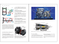
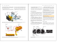
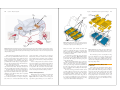
This sample chapter is for review purposes only. Copyright © The Goodheart-Willcox Co., Inc. All rights reserved.
38
Hybrid Drive System
Operation and
Repair
After studying this chapter, you will be able to:
Identify the major parts of a hybrid drive system.
Explain the construction and operation of hybrid
drive assemblies.
List the safety measures that must be followed
when working on high-voltage hybrid drive
systems.
Use on-board diagnostics to find the source of
problems in a hybrid vehicle propulsion system.
Identify the most common problems that occur in
a hybrid vehicle drive system.
Perform basic tests to verify hybrid drive trouble
codes.
Safely remove and replace a hybrid battery pack,
power control module, power cables, ECUs, and
motor-generator assemblies
To identify a hybrid vehicle, look for badging on the
front fender, engine cover, or hood. You can also compare
the vehicle’s VIN (vehicle identification number) to factory reference information. The 5th, 6th, and 7th alphanumeric characters in the VIN identify hybrid vehicles.
Hybrid Vehicle History
In 1898, Ferdinand Porsche, the founder of Porsche
Motor Car Company, designed and built a car that used a
small internal combustion engine to spin a large electric
generator. The generator was then used to power electric
motors at each drive wheel. No clutch, transmission, or
Internal
combustion
engine
Introduction
A hybrid vehicle (HV) uses two individual power
sources to provide energy for propulsion. A hybrid
gas-electric vehicle (HGEV) has an internal combustion
engine and an electric drive system combined into one
vehicle power train. See Figure 38-1. Since hybrid gaselectric vehicles are now produced and sold by many
automakers, it is important that you understand how these
vehicles operate and the methods for safely servicing
them. The electrical/electronic service methods you
learned in previous chapters apply to hybrid vehicles. The
primary concern when working on a gas-electric hybrid
drive train is the extremely high voltage and current stored
and generated by the electric drive devices and circuits.
Besides the gas-electric hybrid, automakers are
experimenting with fuel-cell hybrids, hydraulic hybrids,
and pneumatic hybrids. However, none of these experimental drive systems are presently being mass produced
and used in passenger vehicles.
694
Motor-generator
Figure 38-1. An internal combustion engine and a powerful
electric drive train are used to propel a hybrid gasoline-electric
vehicle. (Honda)
Chapter 38 Hybrid Drive System Operation and Repair
mechanical drive train was used. This first hybrid had
large wires between the generator and the drive motors.
The same basic principle is used today in large locomotives. A locomotive uses a large diesel engine to spin
an electrical generator. The generator can then energize
one or more large electric traction motors that turn the
locomotive’s wheels.
Advances in electric motor and battery technology
have allowed automakers to build hybrid vehicles that
accelerate as well as conventional gasoline-powered
vehicles while reducing the amount of fuel burned in both
city and highway driving. Hybrid vehicles now have the
highest combined average fuel economy numbers of any
type of mass-produced passenger vehicle.
Hybrid Drive Vehicle
In a gas-electric hybrid, the internal combustion
engine and electric drive system work in unison under
computer control to propel the vehicle and operate its
electrical accessory systems. There are six major assemblies in a gas-electric hybrid drive system, Figure 38-2.
• High-voltage (HV) battery pack—large number
of voltaic cells wired in series to produce a highvoltage, high-power storage battery.
• Μotor-generator—armature and stator assembly
that can function as a high-power motor or a highpower generator.
• Power control module—high-voltage electronic
circuit that can change dc to ac or ac to dc. It can
also amplify or reduce voltage.
• Hybrid drive ECU—electronic control unit that
monitors driving conditions to help control the
operation of the power control module, battery
pack, and motor-generator.
• Power cables—large insulated conductors that electrically connect the battery pack, power control
module, and motor-generator assemblies together.
• Ιnternal combustion engine—gasoline or diesel
engine that propels the vehicle at highway speeds
and spins the motor-generator armature to
recharge the battery pack.
A conventional fuel tank, fuel lines, and electronic
fuel injection system feed gasoline or another fuel to the
internal combustion engine. As mentioned, the internal
combustion engine is capable of propelling the vehicle
and providing energy to spin the motor-generator to
recharge the battery pack. The motor-generator can also
be used to propel the vehicle and help slow the vehicle
when the brakes are applied. Both the motor-generator
and the engine work together to provide a dependable
and fuel efficient means of transportation.
695
Hybrids Types
Hybrid vehicles can be broadly grouped into two categories, full hybrids and mild hybrids. A full hybrid uses
the motor-generator to initially accelerate and propel the
vehicle; the internal combustion engine only runs when
the battery pack becomes discharged. Full hybrids can
accelerate normally (not full throttle) without consuming
any fuel or emitting any exhaust emissions.
The full hybrid is propelled by the motor-generator
until the HV battery pack has about a 30% charge
remaining. Then the hybrid drive ECU “fires up” the
internal combustion engine to propel the vehicle and
recharge the HV battery pack.
A mild hybrid is propelled by its internal combustion
engine only. This type of hybrid shuts down its engine
when the vehicle is coasting, braking, or stopped. It then
uses a large starter-alternator to quickly restart the engine
when the brake pedal is released. The starter-alternator
functions as an alternator when the engine is running.
Most mild hybrids have a 36- or 42-volt electrical
system that powers electric motors to drive accessory
items, such as the power steering pump or the air conditioning compressor. In this way, these components continue to work even when the internal combustion engine
is shut down.
Engine/body
ECU
Hybrid drive
ECU
Fuel
tank
Internal
combustion
engine
Battery
pack
Power
cables
Power
control
module
Motorgenerator
3-phase
power cables
Figure 38-2. The major assemblies of a typical gasoline-electric hybrid are shown here. The electric drive train primarily
operates at low vehicle speeds. The internal combustion engine
operates at higher engine speeds or when the battery pack
becomes discharged.
696
Section 5 Electrical Systems
Chapter 38 Hybrid Drive System Operation and Repair
Note!
A few mild hybrids use a small motor-generator
to assist the gas engine in accelerating from a
standstill to about 10–20 miles per hour. This
improves fuel economy slightly but not as much
as the full hybrid drive train.
Battery
pack
Power
control
module
Generator
Hybrid Drive Train Configurations
Hybrids are often classified by the configuration of
their drive train. A series hybrid has a separate generator
and traction motor. It does not use a motor-generator. In
a series hybrid configuration, the traction motor is the
only method used to apply torque to the vehicle’s drive
train. The internal combustion engine has no mechanical
connection to the drive train. At least one major auto
manufacturer is developing a series hybrid for mass production. This is illustrated in Figure 38-3A.
The series hybrid can operate in the all-electric mode
when the battery pack charge is sufficient to propel the
vehicle. When the battery pack becomes drained, the
internal combustion engine starts and turns the generator
to recharge the battery pack.
A parallel hybrid uses both an internal engine and a
motor-generator to apply mechanical torque to the drive
train. The engine and motor-generator operate in parallel,
or at the same time. See Figure 38-3B.
During rapid acceleration, both the engine and the
motor-generator apply torque to the drive train. At low
speeds, the parallel hybrid can operate in full-electric
mode, with the gas engine completely shut down.
A parallel hybrid provides the advantages of an allelectric vehicle in city driving but can perform like a
gasoline engine–powered vehicle under full acceleration
or at highway speeds. The drawback to the parallel
hybrid is that the motor-generator cannot drive the
vehicle and recharge the HV battery pack at the same
time. This limits the amount of time the vehicle is driven
by the motor-generator.
The series/parallel hybrid combines the advantages
of the parallel hybrid with those of the series hybrid. This
type of hybrid can recharge the HV battery pack even
when the electric motor is used to drive the vehicle. The
internal combustion engine can drive the wheels mechanically, but it can also be disconnected from the drive train
so that only the electric drive motor propels the vehicle.
The engine can also power a generator, which recharges
the battery pack. A power splitter is used to transfer
engine and electric motor power through the drive train.
Refer to Figure 38-3C.
Note!
Manufacturers are currently working to develop
plug-in hybrids. These hybrids can be connected to a 120-volt home outlet to fully
recharge the HV battery pack. Then, when the
vehicle is driven the next day, it can operate in
the all-electric mode without starting the gas
engine until the battery is depleted.
Hybrid Vehicle Operation
Motor
Internal
combustion
engine
Drive
out
A
Power
control
module
Battery
pack
All-Electric Drive Mode
Motorgenerator
Transmission
Engine
Drive
out
B
Battery
pack
A typical full hybrid drive system has six basic
modes of operation:
• All-electric drive mode.
• Motor-assist mode.
• Idle stop mode.
• Regenerative braking mode.
• Engine starting mode.
• Battery pack recharging mode.
Power
control
module
Generator
In the all-electric drive mode, the hybrid vehicle
operates just like an all-electric vehicle. The HV battery
pack provides all the energy needed to propel the vehicle.
The gasoline or diesel engine is shut off but is ready to
start up when the battery pack becomes discharged. Refer
to Figure 38-4A.
Many hybrid vehicles will stay in the all-electric mode
when accelerating up to 20–40 mph. If the driver accelerates normally, the hybrid’s electric drive system will propel
the vehicle up to city speed limits without starting the
internal combustion engine. An internal combustion
engine is least efficient when operating at very low rpm.
When backing up, most hybrids operate in all-electric drive—the internal combustion engine remains off.
When a hybrid runs on electrical energy only, it emits no
hydrocarbon emissions and does not burn any fuel.
Motor Assist Mode
Motor
Engine
Power
splitter
Drive
out
C
Figure 38-3. Compare the three types of hybrid drive configurations. A—Series hybrid. B—Parallel hybrid. C—Series/parallel
hybrid. (Toyota)
In the hybrid motor assist mode, both the motor-generator and the internal combustion engine apply torque to
the drive train for propulsion. See Figure 38-4B. Some
hybrid systems start out using only the motor-generator
during acceleration and operate in the motor assist mode
at cruising speeds. Other systems use both the motor-generator motor and the internal combustion engine during
acceleration and while cruising.
Idle Stop Mode
In the idle stop mode, the system automatically shuts
off the internal combustion engine when the vehicle
comes to a full stop and restarts the engine when the
697
vehicle reaches a predetermined speed (about 20–40
mph) or when the HV battery pack has partially discharged. This conserves energy and reduces exhaust
emissions during idle or at other times when the engine is
not needed.
Regenerative Braking Mode
Regenerative braking is an electric braking system
that works in conjunction with the conventional hydraulic
brakes. During regenerative braking mode, the motorgenerator serves as an electrical generator, sending high
current through the hybrid power cables, to the power
control module, and into the HV battery pack. Look at
Figure 38-4C.
When the brakes are applied, a brake pedal sensor
sends a signal to the hybrid ECU, prompting the motorgenerator to function as a generator. With moderate brake
pedal pressure, the conventional hydraulic brakes do not
apply the friction pads into the spinning brake armatures.
Instead, the motor-generator places a drag on the rotating
tires, wheels, and drive train, slowing the vehicle.
When the brake pedal is pressed harder for quicker
stops, the brake pedal sensor signals the computer system
to apply the conventional hydraulic brakes to stop the
vehicle more quickly. If the hybrid vehicle is braked carefully, almost all the kinetic energy of the moving vehicle
is recaptured as electrical energy and forced into the HV
battery pack. The battery pack stores this energy and
sends it to the motor-generator during acceleration to
move the vehicle. Braking may feel different in a hybrid
vehicle since the motor-generator drag slows the vehicle
without applying hydraulic friction brakes.
Note!
In some hybrid systems, the internal combustion
engine often aids the regenerative braking by
opening the engine valves so the engine freewheels and engine compression does not absorb
as much power during deceleration and braking.
Engine Starting Mode
In the hybrid engine-starting mode, the motor-generator spins the engine crankshaft to start the internal combustion engine. The engine then runs to propel the
vehicle at cruising speeds or to drive the motor-generator
when the battery pack has become partially discharged.
The hybrid ECU energizes transmission solenoids
that apply and release clutches in the transmission so the
engine crankshaft and motor-generator are locked and
turn together. The power control module then sends just
enough current to the motor-generator to spin the engine
crankshaft at about 300 rpm.
698
Section 5 Electrical Systems
The hybrid ECU also signals the engine ECU to provide
“spark and fuel” to the engine. The engine ECU electrically
energizes the engine’s fuel pumps, electronic fuel injectors,
and ignition coils while the motor-generator spins the crankshaft until the engine “fires” and runs on its own power.
Battery Pack Charging Mode
After driving a few miles in the all-electric mode, the
HV battery pack becomes partially discharged. When the
hybrid ECU detects the lower voltage (about 70% discharge), it starts the internal combustion engine to propel
the vehicle and recharge the HV battery pack. Refer to
Figure 38-4D. The engine crankshaft spins the motorgenerator, which in turn sends electricity to the power
control module and battery pack.
Chapter 38 Hybrid Drive System Operation and Repair
Hybrid System Voltages
Most hybrids use two voltage systems: a highvoltage (HV) system for the electric drive system and a
12-volt system for most of the vehicle’s conventional
electrical/electronic components. Both systems are wired
separately but interface through the ECUs and the power
control module.
The hybrid high-voltage system typically operates
on voltages that range from around 250 volts up to 650
volts ac or dc. The large conductors and electrical/electronic components in the high-voltage system permit
thousands of amps of current to be fed through the electric drive system. This is enough energy to power several
small homes.
Refer to the vehicle specifications for exact hybrid
operating voltages. Specific voltage levels will vary with
each make and model of hybrid vehicle.
Hybrid nominal output voltage is the maximum dc
voltage available from the HV battery pack. Hybrid nominal
output voltages typically range from about 100 volts to
more than 300 volts. Higher nominal voltages increase the
efficiency of the electric drive system. Hybrid maximum
voltage is the 3-phase ac voltage (up to 650 volts) fed to
the motor-generator from the power control module.
A hybrid low-voltage system uses a conventional
12-volt battery. The low-voltage system is used to maintain computer memory and provide low voltage to electrical accessories. It provides the small amount of current
needed to operate the electronic fuel injectors, fuel
pumps, ignition coils, sensors, and other low-voltage
components. It also powers the dash display, stereo, and
other accessories. See Figure 38-5.
Note!
Some hybrids do not have a 12-volt battery but
instead use a step-down transformer in the
power control module to send 12 volts to the
low-voltage electrical accessories.
Hybrid Drive Assemblies
The following sections detail the construction and
operation of various hybrid drive assemblies used in a
full hybrid. The assemblies used in other types of hybrid
vehicles may vary slightly.
A
699
High-voltage
cables
12-volt battery
Figure 38-5. This hybrid vehicle uses a conventional 12-volt
battery to power low-voltage components. (Honda)
Since a battery pack contains several modules wired
in series, you can use Ohm’s law to calculate the hybrid
nominal output voltage. If one battery pack module produces 7.2 volts dc, you would simply multiply the
number of modules times this voltage. For example, if
there are 38 battery pack modules with 7.2 volts each, the
HV battery pack would produce 274 volts dc. Another
manufacturer’s HV battery pack might have 30 modules
producing 9.6 volts each wired in series for a nominal
output voltage of 288 volts.
Power cables allow the battery pack to be fastened to
the power control module. Positive and negative cables
B
Battery Pack
C
D
Figure 38-4. Study the basic modes of hybrid operation carefully. A—In the all-electric mode, the battery pack provides the energy
to propel the vehicle. B—The motor assist mode is often used during rapid acceleration. C—In the regenerative braking mode, the
motor-generator acts as an electric generator that places a drag on the drive train to help slow the vehicle. At the same time, current flow out of the motor-generator recharges the battery pack. D—In the battery recharging mode, the motor-generator is locked
to the crankshaft or transaxle gears to spin and act as a generator to recharge the battery pack.
The hybrid battery pack sends high-voltage dc into
the power control module, which converts it to ac or
changes it to a higher or lower voltage. This ac voltage is
then fed to the motor-generator for propelling the vehicle
or starting the internal combustion engine.
A battery pack contains several high efficiency NiMH
(sealed nickel metal hydride) battery modules stacked in a
sealed enclosure and wired in series to produce a highvoltage power source. The battery pack is normally
mounted in the rear of the chassis, often behind or under
the rear seat or in the trunk area. See Figure 38-6.
NiMH battery packs are designed to handle very high
current flow rates during charging and discharging. A
NiMH battery pack also has a good weight-to-power out
ratio. Even the largest battery pack weighs only about
200 lbs (90 kg).
Depending on the make and model of the vehicle and
the number of modules used, hybrid battery pack voltage
can range from about 150 volts up to approximately 300
volts dc.
Figure 38-6. The HV battery pack is enclosed in a metal
housing. Note the large orange power cables that connect the
battery pack to the power control module. (Toyota)
700
Section 5 Electrical Systems
Chapter 38 Hybrid Drive System Operation and Repair
are bolted to the power control module to ensure a good
electrical connection.
A battery pack cover encloses the modules and protects them from damage. It also protects people from
electric shock. Battery pack cover(s) are held on with
machine screws. Some hybrids have the power control
module and battery pack housed together.
Warning!
Never remove a cover from a hybrid battery
pack. The manufacturer’s warranty may become
void if the cover is removed. Additionally, if
you touch a battery pack cable with your bare
hands, you can be electrocuted!
Battery pack temperature sensors are used to protect
against heat damage. A tremendous amount of current
flows in and out of the battery pack when the battery is
being recharged and when it is powering the motor-generator(s). If a battery pack temperature sensor detects cell
overheating, it will signal the hybrid ECU to disconnect the
power control module, preventing further overheating.
If a battery problem exists (extended battery service
life, impact damage from a collision, hit from lightning,
short in cell, etc.), the ECU will instantly shut the electric
drive system down and trigger a malfunction indicator
light in the dash.
Motor-Generator
A hybrid motor-generator functions as both a powerful traction motor and as a high-energy alternator in the
vehicle’s power train. The hybrid motor-generator(s) has
several functions:
• Helps power the drive train and propel the vehicle.
• Recharges the HV battery pack.
• Cranks the internal combustion engine.
• Ηelps slow and stop the vehicle.
The basic parts of a motor-generator include the
armature, stator, and housing. The armature consists of a
set of permanent magnets mounted inside a segmented
steel disc. See Figure 38-7A. The stator is a set of sta-
Armature
Iron cores
Permanent
magnets
A
Motor-generator
housing
C
Coil windings
B
Armature spins
inside stator
Stator
D
Figure 38-7. Study this simplified drawing of a hybrid motor-generator assembly. A—The armature is a steel ring with permanent
magnets imbedded in its outer diameter. B—The stator is made up of coils consisting of sets of windings wrapped around iron cores.
C—The motor-generator housing holds the stator coils stationary. D—When assembled, the armature and stator form an assembly
that can function as a high-torque motor or a high-energy generator.
tionary coil windings wrapped around iron cores and
arranged around the armature, Figure 38-7B. The motorgenerator housing holds the stator assembly in place
around the armature. It also fastens the motor-generator
to the rear of the engine, inside the transmission/
transaxle, or in the rear drive axle assembly, Figure 38-7C.
When the motor-generator is assembled, Figure 38-7D,
the armature spins in close proximity to the stator
assembly.
High-voltage,
high-current
connector
701
Segmented
armature with
permanent
magnets
Motor-Generator as a Motor
A hybrid motor-generator is usually a synchronous,
ac permanent magnet, brushless motor-generator design.
There are no electrical windings in the armature and no
electrical connections to it. The permanent magnet
design improves reliability over dc motors that have
armature windings, which can fail.
The term synchronous means the rotation of the
armature is synchronized, or timed, with the 3-phase
alternating current entering the stator windings. The
3-phase ac sets up a 3-wave magnetic field that moves
around the stator, pushing and pulling the armature
around with it. The 3-phase ac is delivered to the
motor-generator through three cables. Each of the
cables carries a single phase, or waveform, of alternating current. Each phase is staggered in time from the
others.
Modern hybrids use 3-phase ac power for the same
reason that industrial applications and factories have used
this form of electrical energy for decades. A 3-phase ac
motor can produce more horsepower and torque than an
equal-size dc motor while consuming less electrical
energy. When the 3-phase ac motor-generator is functioning as a generator, it can produce more electricity
than a comparable dc generator.
The motor-generator in Figure 38-8 uses 18 coil
windings (electromagnets) and iron cores organized
around the armature. Since the outer surface of the armature is close to the stator windings, the permanent magnetic fields and the electromagnetic fields can repel or
attract each other with great force.
As the ac voltage cycles from positive to negative in
the stator coils, it generates alternating north and south
magnetic poles in the motor-generator electromagnets.
Current is passed through each set of coil windings in a
circular pattern so that the armature is rotated with the
movement of the magnetic fields.
Each armature pole is “pushed” around by magnetic
repulsion. The adjacent armature pole is “pulled” by
magnetic attraction. With multiple poles (permanent
magnets) on the armature and multiple electromagnets in
Figure 38-8. This motor-generator is for a parallel hybrid drive
system. Note the segmented steel armature, which is located
inside the stator. (Honda)
the stator, the motor-generator can generate high torque
to propel the vehicle. Refer to Figure 38-9.
Basically, motor-generator torque is controlled by
current flow, while speed is controlled by the frequency
and phase shift of the alternating current waves.
Motor-Generator as a Generator
The motor-generator acts as a generator during
regenerative braking and when being driven by the
internal combustion engine to recharge the HV battery
pack. When the motor-generator is functioning as a
generator, the internal combustion engine or drive train
components spin the motor-generator’s permanent
magnet armature. The magnetic field produced by the
permanent magnets cuts across and through the stationary
702
Section 5 Electrical Systems
Chapter 38 Hybrid Drive System Operation and Repair
Phase 3
Phase 1
Phase 3
Phase 2
C
A
B
Phase 1
A
Phase 1
A
Phase 1
Front
motor-generator
rotor
Front
motor-generator
windings
Internal combustion
engine
Rear
motor-generator
windings
Dual Motor-Generator Hybrids
Phase 2
(+)
As shown in Figure 38-10, the single motor-generator is the least complex type of hybrid drive train. Note
how the large motor-generator (shown in red) bolts
between the cylinder block of the engine and the housing
of the transaxle.
703
Phase 2
Phase 3
A dual motor-generator hybrid uses two separate
motor-generators to provide assist. The two motor-generators are usually located inside the transmission or
transaxle. Look at Figure 38-11.
During regenerative braking, both motor-generators
act as large ac generators to recharge the HV battery pack
and help drag the drive train to a stop. Under all-electric
drive, both motor-generators act as motors to help propel
the vehicle. A cutaway view of a rear-wheel drive transmission with two hybrid motor-generators is shown in
Figure 38-12.
Rear
motor-generator
rotor
Triple Motor-Generator Hybrids
B
In some cases, three motor-generators are used in a
hybrid vehicle, Figure 38-13. Two motor-generators are
located in the transmission or transaxle, and one is
located in the rear drive axle assembly.
A triple motor-generator arrangement is often used in
large four-wheel drive vehicles to help electrically drive
all four wheels. Figure 38-14 shows a front hybrid
transaxle and a rear hybrid transaxle for a three motorgenerator hybrid driveline.
Figure 38-9. Three-phase ac flows through the three power
cables that run between the motor-generator and the power
control module. A—Three-phase ac is used to spin the armature in this motor-generator. Phase 1 current attracts armature
pole A. Phase 2 attracts armature pole B. Phase 3 attracts
armature pole C. B—Three-phase alternating current is simply
three single ac phases timed 120 degrees apart. The voltage
waves (shown as voltage waveforms) generate magnetic fields
that circle inside the motor-generator to make the armature
spin. (Toyota)
A single motor-generator hybrid uses only one large
motor-generator to assist the internal combustion engine.
This is a compact design with the motor-generator
assembly bolted to the rear of the engine block, in front
of the transaxle or transmission. The motor-generator
armature is connected to an engine crankshaft and to the
transmission input shaft.
Front motor-generator
Rear motor-generator
Stator
Stator
Rotor
Rotor
To
propeller
shaft
Power cable
junction box
Continuously
variable
transaxle
Engine
crankshaft
Figure 38-12. Study the major components of a hybrid transmission for a rear-wheel drive vehicle. (Toyota)
stator windings. This induces ac current in the stator windings and power cables leaving the motor-generator.
Single Motor-Generator Hybrids
Figure 38-11. In this series-parallel hybrid configuration, the transaxle contains two motor-generators. To improve fuel economy, the
gas engine shuts off when braking, when stopped, and when initially accelerating. (Toyota)
Internal
combustion
engine
Power Control Module
Motor-generator
Figure 38-10. Study this parallel hybrid arrangement. Note that
the single motor-generator is located between the engine block
and transaxle. The motor-generator can assist the gas engine
to propel the vehicle. The motor-generator can also serve as a
generator to recharge the battery pack. (Honda)
The hybrid power control module consists of a set of
electronic circuits that alter current and route it between
the HV battery pack and motor-generator. It controls how
much and what kind of current flows through the power
cables. The power control module also controls the speed
and torque of the traction motor by varying ac frequency
and phase shift. See Figure 38-15.
The hybrid power control module is often located
next to the battery pack, on the transaxle, or on top of the
engine. The power control module normally contains a
converter circuit, an inverter circuit, and a motor-generator ECU.
704
Section 5 Electrical Systems
Chapter 38 Hybrid Drive System Operation and Repair
Compound
gear unit
Motor-generator 1
Motor-generator
cables
Engine
Hybrid
transaxle
Rear
transaxle
Inverter
Battery pack
cables
HV
battery
Figure 38-15. Most hybrid power control modules have two
orange cables that connect to the battery pack and three large
orange cables that connect to the motor-generator. (Honda)
Motor-generator 3
Motor-generator 2
Figure 38-13. This all-wheel drive hybrid drive train uses two motor-generators in the transaxle and a third motor-generator in the
rear drive axle assembly.
Motor-generator 2
Motor-generator 1
Stator
Motor-generator 3
Stator
Rotor
The converter circuit in the power control module
can step dc voltage up or down. It does not change ac to
dc or dc to ac. Hybrid battery pack voltage must usually
be stepped up to efficiently drive the inverter circuit and
the motor-generator. Battery pack voltage must be
stepped down to charge the vehicle’s 12-volt battery.
An inverter circuit in the hybrid power control
module changes dc to ac and ac to dc. When high-voltage
dc is fed into the inverter circuit from the battery pack for
electric propulsion, the inverter circuit changes it to highvoltage 3-phase ac to run the motor-generator. When
3-phase ac is fed into the inverter circuit from the motorgenerator, the ac is changed back into high-voltage dc for
recharging the battery pack.
The motor-generator ECU controls the inverter and
converter circuits to efficiently operate the motor-generator(s). The motor-generator ECU responds to control
signals from the hybrid ECU and transaxle ECU.
Rotor
Battery Relays and Contactors
Front Transaxle
Rear Transaxle
(with 4WD System)
Figure 38-14. Compare the construction of a front hybrid transaxle to that of a rear hybrid transaxle. (Toyota)
Battery relays and contactors are used to control the
flow of electricity between the battery pack and the
power control module. As shown in Figure 38-16, when
the ignition key is off and battery relays are open, the
large high-current contactors are also open and no battery
voltage can flow to the power control module and motorgenerator.
However, when the ignition key is turned to run, the
ECU energizes the battery relays. The relays close and
send current to the large contactor coils, which pull the
contactor lugs closed. High voltage and high current can
then flow through the contactor lugs to the power control
module.
705
Hybrid Drive ECU
The hybrid drive ECU controls the power control
module and motor-generator to keep the HV battery pack
operating at the optimum temperature and state of charge.
It helps utilize battery power efficiently and properly
recharge the HV battery pack when partially drained by
activating the regenerative braking system. By keeping
the HV battery pack at optimum charge and temperature,
the hybrid drive ECU increases battery service life and
fuel economy.
When the accelerator of a hybrid is depressed, a
pedal position sensor sends a signal to the hybrid drive
ECU. The hybrid ECU determines whether to drive in the
all-electric mode (slow acceleration), start the gas engine
(rapid acceleration), or use a combination of gas engine
and electric drive based on information in its memory.
Power Splitter
A hybrid power splitter is a planetary gearset used to
control the transfer of power through the hybrid drive
train. The hybrid power splitter and transaxle are under
computer control.
When the driver moves the gearshift selector in the
passenger compartment, an electric signal is sent from
the shift lever position sensor to the hybrid ECU. The
hybrid ECU then energizes or shuts off specific solenoids
in the transaxle. The solenoids can apply or release friction bands or clutches to hold or release members of the
power splitter. By holding or releasing different parts of
the power splitter, the solenoids control the planetary
gearset(s) and the flow of torque from both the internal
combustion engine and the electric drive system. When a
motor-generator is operating as a generator, the splitter
can transfer driveline torque into the motor-generator
armature during braking or coasting.
As shown in Figure 38-17, the engine crankshaft is
connected to a shaft running through the front motor-generator and into the planetary gearset. The planet carrier is
splined to the engine crankshaft. The planet ring gear is
connected to the front motor-generator armature. The
rear motor-generator is connected to the front motor-generator and to a reduction gear mechanism.
Hybrid Power Cables
Hybrid power cables transfer extremely high-voltages to the components of the electric drive system. The
power cables are heavily insulated to prevent these voltages from shorting to ground.
Two large power cables connect the battery pack to
the power control module. Three large power cables
706
Section 5 Electrical Systems
Chapter 38 Hybrid Drive System Operation and Repair
Motor-generator 2
Motor-generator 1
3-phase AC
0.0
DC voltage
Contactor
open
Volts
– DC +
Electric
motorgenerator
Gas engine
HV Battery
3
2
Power
control
module
+
–
4
1
3
Ground
fault
monitor
Contactor 5
relays closed
(relays off)
Sun gear
(generator)
Planetary
carrier
(engine)
12-Volt
Battery
Pinion
gear
Ring gear
(motor/output
axle)
Reduction
gear unit
connected
to the final
drive
High Voltage Safety System—Vehicle Shut Off (Ready off)
Contactor
closed
274
Motor-Generator Sensor
A motor-generator sensor is used by the hybrid drive
system to detect armature speed and position, Figure 38-18.
A rotor on the motor-generator’s armature spins inside
three sensing coils. The motor-generator sensor produces
ac signals, which are sent to the power control module.
Based on these signals, the power control module
changes the amount of current and the phase shift of the
3-phase ac for efficient motor-generator operation.
Hybrid Drive Cooling
The motor-generators, battery pack, and power control module carry tremendous amounts of electrical
energy and can become hot from the high current flowing
through them. There are three methods used to remove
heat from these components.
Hybrid water cooling circulates engine coolant
through the transaxle, the motor-generators, and power
control module, as shown in Figure 38-19. Coolant is
HV Battery
Speed sensor
(resolver)
Volts
– DC +
Electric
motorgenerator
+
Power
control
module
–
Ground
fault
monitor
Contactor
relays closed
(relays on)
12-Volt
Battery
High Voltage Safety System—Vehicle On and Operational (Ready on)
Figure 38-16. Note how the battery relays operate the large electrical contactors. The relays and contactors work in conjunction to
disconnect battery pack energy from the electric drive train. Note that the DVOM shows no voltage to the power control module until
the relays close the contactors.
connect the power control module to the motor-generator.
These three cables are normally routed under the floor
pan on the inside of the rocker panel. The three highvoltage power cables have orange insulation to warn
technicians of their danger.
Large eye-type connectors are soldered to each end
of the power cables. This allows the cables to be bolted to
the power control module and to the motor-generator
assembly.
707
Hybrid Ground Fault Interrupter
A hybrid ground fault interrupter constantly monitors the system for high-voltage leakage into the metal
chassis of the vehicle. If high voltage from the battery
pack or motor-generator is shorting to frame ground, the
ECU will illuminate a warning light and de-energize the
main power relays (contactors) to disconnect the HV battery pack from its drive circuit.
Figure 38-17. A power splitter can be used to change power flow
and rotating speeds inside a hybrid transaxle or transmission.
The main power relays will also open to disconnect
the battery during air bag deployment. If the vehicle is in a
collision serious enough to trigger an impact sensor, the
vehicle ECUs will also cut power to the HV battery pack
contactors so power cannot enter the power control module
and other components in the high-voltage system.
Excitation
Coil A
Impact Sensors
Impact sensors, or inertia switches, open during a
severe impact to open the high-voltage hybrid circuits,
disable the electric fuel pumps for the gas engine, and
deploy the air bags. If the air bags have deployed, you
must follow manufacturer instructions to replace the air
bags and re-energize the electric drive system.
High-Voltage Fuse
A high-voltage fuse will open and disconnect the
battery pack power if current flow becomes too high due
to a short. If no power is reaching the electric drive
system, find out why the fuse burned open, correct the
problem, and install a new high-voltage fuse.
Detection
Coil S
Detection
Coil C
Figure 38-18. The motor-generator speed sensor uses a small
rotor keyed to the armature shaft to induce current in three
pickup coils. As the armature spins, the sensor sends out an
armature speed signal. This signal allows the ECUs and the
power control module to monitor motor-generator speed.
708
Section 5 Electrical Systems
Chapter 38 Hybrid Drive System Operation and Repair
routed through the hybrid drive components to carry heat
back to the radiator for transfer into the atmosphere. The
hybrid often has two radiators: the conventional engine
radiator and the hybrid drive radiator.
Hybrid air cooling circulates outside air through the
battery pack enclosure and then forces this air out of the
vehicle. The air carries away heat and vents electrolyte
gases away from the vehicle. Forced battery pack ventilation is often provided by an electric blower motor that
directs outside air through the battery pack enclosure.
See Figure 38-20. The 12-volt blower motor is similar
to that used in a passenger-compartment climate control
system. The hybrid ECU and battery temperature sensors
control the operation of the blower.
Hybrid refrigerant cooling routes R-134a refrigerant
through a separate evaporator located next to the power
control module or battery pack. The refrigerant flow
cools the evaporator, as well as the hybrid components.
Hybrid Dash Display
Power control
module
Hybrid drive
radiator
Reservoir
tank
Water
filler
Engine
radiator
Hybrid
transmission
Electric
water pump
Figure 38-19. This hybrid drive uses an extra radiator to remove excess heat from the hybrid drive system. Keeping hybrid components cool increases electric power transmission efficiency and protects them from thermal damage. (Toyota)
Battery pack
air inlet
Battery pack
housing
A combination meter or cluster in the dash of a
hybrid displays many variables pertaining to the performance and condition of the gasoline engine and electric
drive system. The combination meter contains the
speedometer, odometer, fuel gauge, engine gauges,
hybrid power display, and the hybrid drive ready light, as
well as several warning lights. One design is shown in
Figure 38-21.
A hybrid power display in the combination meter
informs the driver of the hybrid drive operating conditions. Many hybrid displays will indicate when the electric “assist” is working, how electrical energy is being
used, and how much energy remains in the battery pack.
The power display often reads in kilowatts (Kw) of power
output from the HV battery pack. This display helps the
driver utilize and recapture as much energy as possible
while driving.
A hybrid drive ready light often blinks when you
press the brake pedal and turn the ignition key to the start
position with the gear selector in park. When the electric
drive is engaged, the ready light glows continuously to let
you know the vehicle is ready to be driven.
Discharge
warning light
Malfunction
indicator lamp
709
A hybrid master warning light in the combination
meter warns if there is a problem in any part of the drive
train. If the hybrid ECU detects any abnormal condition
in the electric drive circuitry or related components, it
will illuminate the master warning light to notify the
driver that something is wrong.
A battery pack warning light in the combination meter
illuminates if the battery’s state of charge is below normal
limits. This could be caused by leaving the key on too long
when parked, running the air conditioning too long on battery pack energy, a shorted battery pack, or a circuit problem
preventing the battery pack from being recharged normally.
A conventional malfunction indicator light (MIL) turns on
when any ECU detects a vehicle malfunction.
Hybrid Service Safety
Modern gas-electric hybrid drive systems generate
enough electrical energy to cause electrocution. It takes
only a couple amps of current flowing through your body
to stop your heart and kill you. Most hybrid vehicles conduct almost 600 volts ac and 300 volts dc at hundreds
of amps. By comparison, home wall outlet voltage is
120 volts ac.
Remove Jewelry
Remove all jewelry when working on a hybrid’s
high-voltage circuits. It is very easy for a metal watch to
short between a high-voltage conductor and ground since
high voltage can arc through the air and into the jewelry.
Master warning
light
Blower
motor
Battery pack
modules
Airflow
To outside
A - A Cross Section
Figure 38-20. Air cooling is used to remove heat from the battery pack. A blower pulls air from the passenger compartment, routes
the air over the battery pack, and then forces the heated air to the outside of the vehicle.
HV battery
warning light
Ready light
Figure 38-21. The hybrid dash display will provide information about the mode of operation and the condition of the electric portion
of the drive train. (Toyota)
710
Section 5 Electrical Systems
The high voltage can instantly make the metal watch glow
red hot, burning deep into your wrist or arm. If a metal
necklace touches high-voltage conductors, it can weld
itself to the conductors. It will then glow red hot, begin to
melt, and may even explode in sparks of molten metal.
Wear Eye Protection
Make sure you wear safety glasses or goggles when
working on high-voltage hybrid components. If a highvoltage cable shorts to ground, a violent electric arc will
occur. The metal end of the shorted cable will melt and
may shoot out molten metal. If the molten metal gets in
your eyes, you can suffer permanent eye injury.
Wear Insulating Gloves
Always wear thick rubber insulating gloves when
working on hybrid power cables and other hybrid components. The high voltage in hybrid vehicles can arc
through cloth or thin rubber gloves, causing serious
injury or death. Make sure you use OSHA approved
“lineman gloves” or gloves with an approved insulation
value of 1000 volts. See Figure 38-22.
Periodically inspect your insulating gloves for tears
or splits, especially in the fingertips. To check the condition of insulating gloves, grasp a glove by the cusp and
fold it over a couple times to seal air inside the glove.
With the glove filled with air, check for air leakage and
flaws. If the glove leaks air, it can also leak voltage. If
Chapter 38 Hybrid Drive System Operation and Repair
your gloves are worn or damaged, discard them and purchase new ones.
Wear Rubber-Soled Shoes
Since the voltages are so high in a hybrid, you should
wear shoes with rubber soles when working on hybrid
vehicles. Rubber soles help insulate your body from earth
ground, preventing high voltage from arcing out of the
high-voltage conductors and into your body while
seeking earth ground (conduction of electricity into the
shop floor).
Note!
If a hybrid is in a severe collision, the hybrid
drive system will automatically disable the
high-voltage drive system. Many systems will
disable the battery pack and generator when the
air bag deploys.
Create a High-Voltage Buffer Zone
Keep a Fire Extinguisher Nearby
Always keep a class A, B, C fire extinguisher near the
work area when servicing hybrids. A high-voltage electrical short can cause a serious electrical fire. If fire starts,
shut off the main contactor or switch for the battery pack
and then put out the fire with a fire extinguisher.
Towing Safety
With some hybrids, spinning the wheels and axles
will cause the motor-generator to produce high voltage,
which can be dangerous and may damage the drive
system. Therefore, when towing or moving a hybrid
vehicle, the drive wheel engaged to the motor-generator
should be raised off the ground.
The front wheels of a front-wheel drive hybrid
should be raised when towing. If you are towing an allwheel drive hybrid with motor-generators at the front and
rear, all four wheels should be raised off the ground.
Disable the Hybrid Drive when Working
Figure 38-22. Learn to respect the power of a hybrid electric
drive system. A—Wear thick rubber gloves to help insulate your
body from the high voltages in a hybrid drive. (Toyota)
backward by the motor-generator if you accidentally
press the accelerator. This could cause the vehicle to
lunge forward or backward and ram into a shop wall or
over co-workers.
A “hot hybrid” system is one with high and low
voltage still present in the electric drive system. Although
you cannot turn off the power stored inside the battery
pack, you can disconnect it from the rest of the hybrid
drive system.
To disable a gas-electric hybrid for repair, you must
first turn the ignition key off. This will cause the hybrid
ECU to de-energize the relays that connect the battery
pack to the rest of the system. Some automakers also
require that you disconnect the conventional 12-volt battery to help prevent the high-voltage circuits from accidentally being energized.
Disabling the system is important because a hybrid’s
drive train may be engaged and ready to accelerate even
without the internal-combustion engine running. If you
leave the key on in a hybrid and the shift lever is in gear
(drive or reverse), the vehicle can be propelled forward or
When working on a gas-electric hybrid, set up a
high-voltage buffer zone of about three feet (1 meter)
around the perimeter of the vehicle. You do not want steel
workbenches, large metal equipment, co-workers, or any
other potential conductors of electricity in the buffer
zone. Take the time to move objects or park the hybrid
vehicle away from potential conductors. If you back your
body into a good conductor, such as a steel workbench,
with your arm touching a source of high voltage, you
could be electrocuted or severely injured as the voltage
travels through your body to ground.
High-Voltage Disconnect
A high-voltage disconnect is provided on a gas-electric hybrid to allow the battery pack to be physically disconnected from the power control module. Refer to
Figure 38-23. With many hybrids, you must pull out the
disconnect to produce an open circuit between the battery
pack and the power control module. With other designs,
you must rotate a high-voltage disconnect switch to provide an open in the battery pack circuit.
Hybrid high-voltage disconnects are usually located
near the battery pack in the trunk, under the seat, on the
side of a seat under a trim panel, or in other similar locations. Refer to the factory service literature for details.
Warning!
To prevent electric shock, wait at least five minutes after removing the high-voltage disconnect
before working on the high-voltage circuits. It can
take up to five minutes for any high-voltage
capacitors in the inverter circuit to discharge fully.
Note!
After you remove a high-voltage disconnect,
remove the high-voltage fuse and keep it in
your pocket. This will prevent anyone from
accidentally reconnecting battery pack power
when circuits are being serviced.
711
Hybrid Problem Diagnosis
Hybrid vehicles have very extensive on-board diagnostic systems that will help you locate the source of
system problems. The on-board diagnostic system will
monitor hundreds of operating conditions and turn on one
or more warning lights if any monitored condition is not
within specifications. Figure 38-24 shows a few of the
problems that can affect hybrid electric drive operation.
A glowing malfunction indicator light lets you know
that you should use a scan tool to retrieve stored trouble
codes. Figure 38-25 shows a hybrid drive trouble code
index chart. This chart explains what each code means
and where to go in the service information to find instructions for further testing the circuit.
Hybrid Battery Pack Service
Hybrid battery packs have a warranty from the
vehicle manufacturer. One automaker offers a full battery
pack replacement warranty for up to 8 years or 80,000
miles. Battery packs are very dependable and seldom fail.
Nevertheless, they can lose efficiency after a period of
extended service. The electrolyte and the metal plates in
the battery pack can be depleted after years of operation.
Note!
Hybrid NiMH batteries should not be stored for
long periods of time. When purchasing used
battery packs from salvage yards, find out how
long the battery pack has been in storage. If a
battery is left uncharged for over a year, the battery plates and electrolyte will deteriorate and
the battery should not be purchased. Order a
new battery pack to prevent comebacks.
Battery Pack Recharging
With some hybrids, the internal combustion engine
will not start if the battery pack is drained or dead. This
occurs when someone accidentally leaves the headlights
or other electrical accessories turned on when the vehicle
is not running.
A hybrid battery charger uses a step-up transformer
to force high voltage back into the battery pack to reenergize it. Follow the battery charger and vehicle manufacturer instructions for safely connecting the charger
cables to the battery pack. See Figure 38-26. Procedures
vary with make and model hybrid. If the battery pack will
not take a full charge, it should be replaced.
If the hybrid has a 12-volt battery, you can usually
jump-start the hybrid with jumper cables and a 12-volt
712
Section 5 Electrical Systems
Chapter 38 Hybrid Drive System Operation and Repair
booster battery. However, never try to jump start the HV
battery pack with a 12-volt booster battery, or the booster
battery could explode!
Drained or shorted
HV battery pack
Hybrid ECU
failure
Battery Pack Testing
Powertrain
ECU failure
Loose or
damaged
power cables
Service plug
A
Motorgenerator
problems
713
Power control
module problems
Figure 38-24. Note some of the problems you may encounter
when repairing a hybrid drive train.
To check battery pack performance, connect a scan
tool to the diagnostic connector on the vehicle and test
drive the hybrid. Watch the combination meter in the
dash as you accelerate and brake. Also use regenerative
braking to try to recharge the battery pack.
The combination meter and scan tool will indicate
battery pack state of charge (SOC) as a percentage of
total charge. They will also show battery voltage, current
draw, and recharge current.
Hybrids often keep their battery pack SOC at approximately 80%. If the battery pack SOC drops below a
preset level, the battery ECU signals the hybrid ECU to
start the engine and use the motor-generator as a generator is up to almost a full charge.
B
Service plug
Glove
C
Figure 38-23. Hybrid power disconnects can be difficult to find. A—This disconnect plug is located in the trunk of the vehicle.
B— Here you must rotate a locking switch before you can remove the fuse disconnect. C—This hybrid disconnect plug is located
on the side of the rear seat, under a plastic trim piece. (Ford and Toyota)
* 1: These DTCs are indicated by a blinking IMA system indicator when the SCS line is jumped with the HDS.
* 2: To determine the correct troubleshooting procedure for these DTCs, jump the SCS line with the HDS, and read the
flash code.
Figure 38-25. This chart lists hybrid trouble codes from one automaker. If you get a code PO562, you would go to pages 12–39 in
the service manual to get further instructions for testing and servicing the battery condition monitor. (Toyota)
714
Section 5 Electrical Systems
Chapter 38 Hybrid Drive System Operation and Repair
HV
battery
Rear
seat
Aux
battery
715
Upper
cover
Service
hole cover
HV battery
module
Junction
block
Cooling
fan
Frame
wire
Frame
wire
Battery ECU
connector
Battery
charger
Figure 38-26. A high-voltage battery charger is needed if the battery pack becomes drained and will no longer start the gas engine.
The battery charger is connected to ground and to the battery pack positive at special service connectors. Then the charger is turned
on to force electrical energy back into battery pack. After charging, test-drive the vehicle to make sure the motor-generator will
charge the battery. (Toyota)
When test driving the hybrid in the electric mode, it
is best to drive up a small hill. This will increase load on
the motor-generator and draw more current from the battery pack. Compare battery performance to that of a
known good battery or to specifications. If the battery
pack will not take or hold a charge or output enough current for a sufficient amount of drive time in the all-electric mode, replace the battery pack.
If the battery SOC goes down too quickly when driving in the all-electric mode, the battery electrolyte and
plates have probably deteriorated due to prolonged service.
If onboard diagnostics and your test drive indicate
poor battery capacity, the entire battery pack must be
replaced. Battery modules should not be replaced individually. If one module has failed, others are probably
weak and ready to fail.
If your scan tool indicates high battery temperature,
use an infrared thermometer to compare cell temperatures. The use of an infrared thermometer will help
prevent electrocution, as it does not have to contact the
battery directly. If only one cell runs warm, it is probably
shorted and the battery pack must be replaced. If all the
battery cells are warm, a battery cooling system problem
may exist.
If an air cooling system is used, check for a blower
motor circuit problem or a mechanical problem. If the fan
comes loose from the blower motor, it will not set a
trouble code. Blocked or damaged intake air ducts also
create problems. The vehicle owner may inadvertently
place objects over the battery air intake vent. Ductwork
can also be damaged and restricted during a collision.
Battery Pack Replacement
Hybrid battery packs are usually located in the trunk
area or under the rear seat cushion or floor pan,
Figure 38-27. The most common reason for battery pack
replacement is physical damage. A severe collision can
Seat rails
Figure 38-27. Hybrid battery packs are normally located in
trunk area or under the rear seat cushion. Remove the rear seat
or trim panels to gain access to the battery pack.
damage the battery pack elements and short them
together by penetrating the battery cell isolators. The
battery pack electrolyte is an alkaline gel that surrounds
the battery plates. This gel will not leak out of the battery
even if the case is broken.
To begin battery pack removal, remove the interior
trim or carpet over the battery, Figure 38-28. Unfasten
the metal cover and any ductwork that prevents battery
pack removal. This will expose the battery pack, power
relays, and other units.
While wearing insulated rubber gloves, remove the
large nuts or fasteners that secure the high-voltage power
cables to the battery pack. To prevent a high-voltage
short, wrap electrical tape around the metal terminals on
the ends of the orange power cables. You do not want
them to accidentally contact anything and conduct highvoltage electricity.
To remove a battery pack, unbolt it from the vehicle
as required. Then use an engine crane or have someone
help you lift the battery out of the vehicle. The battery
pack should be handled carefully since it contains a
tremendous amount of stored electrical energy and can
be very heavy. A hybrid battery pack can weigh over
200 pounds (90 kg). Make sure your helper is wearing
eye protection and thick rubber insulated gloves.
HV battery
modules
Figure 38-28. Remove the metal cover over the battery pack.
This will expose the battery modules, battery ECU, cooling
fans, and other units that affect battery performance. (Toyota)
Place the battery pack on a wooden pallet for shipment to an authorized recycler. Cover the battery pack
with a box or place it in a shipping container. Place
warning tape or high-voltage warning labels on the outside of the box or shipping container to warn others of the
high-voltage danger inside.
Checking HV Battery Relays and
Contactors
If the trouble codes and symptoms indicate that the
battery is okay but battery power is not reaching the
power control module, check the operation of the battery
relays and contactors. The contactors turn such a high
electrical load on and off that their lugs can become
burned and pitted. If burned enough, the lugs will
develop high resistance and will not be able to carry
enough current to the power control module and motorgenerator. Refer to factory service information for relay
and contactor test points.
716
Section 5 Electrical Systems
Caution!
When measuring high voltage levels in a gaselectric hybrid drive with a VOM, use a highvoltage meter with test leads having thick
insulation. If you use a conventional VOM and
test leads, they can be damaged by the high
voltage in the hybrid system.
Chapter 38 Hybrid Drive System Operation and Repair
717
Low-voltage
battery
cable nuts
KΩ
DC/DC
converter
electrical
connector
Servicing Hybrid Power Cables
The hybrid power cables are normally trouble free.
However, they can become damaged during a collision or
their metal ends can become loose or corroded. Some
high-voltage cables have special watertight terminal
ends, Figure 38-29. However, most hybrids use an eyetype connector that is secured to a threaded metal stud
with a nut.
To check the power cables, note conductor resistance
values of the high-voltage circuit in the data list display
of your scan tool. If these values are not within specs,
tighten or repair the cable ends or replace the hybrid
power cables if needed.
If your scan tool reading shows a ground fault
problem with the cables, they may be leaking current to
frame or body ground. Touch your ohmmeter test lead on
one end of the cable terminal and connect the other meter
lead to frame or body ground. If the ohmmeter reading is
lower than specs (usually around 350k ohms), the insulation may be leaking high voltage to ground and the cable
should be replaced. See Figure 38-30.
A loose cable end can overheat and burn the electrical
connection. Always torque the hybrid cable fasteners to
Figure 38-30. By connecting an ohmmeter between each drive
cable and ground, you can find any cable that is leaking
voltage. The cable’s insulation may have broken down, allowing
small amounts of current to leak out of the circuit. (Toyota)
factory specifications using a torque wrench to ensure the
connection is not too loose or too tight.
To replace a high-voltage power cable, disconnect
both ends of the cable. Remove the clips that secure the
power cable to the vehicle. Finally, install the new power
cable in reverse order of removal.
Servicing Power Control Module
A trouble code will normally be set when problems
develop in the power control module. Sometimes a circuit board in the power control module will fail and
require replacement. A lack of normal air or coolant flow
can cause power control module overheating, which will
also set trouble codes.
Some hybrid vehicles use separate converters. For
example, Figure 38-31 shows a dc-to-dc converter that
mounts in the engine compartment. If your scan tool indicates internal converter problems, the defective converter
should be removed and replaced.
DC/DC
converter assembly
Figure 38-31. This dc-to-dc converter is a discrete unit. It mounts in engine compartment on firewall of vehicle. (Ford)
Figure 38-32. With a liquid system, disconnect the hoses
and wires going to the pump motor before replacement.
Servicing the Motor-Generator
Blower
Servicing the Hybrid Cooling System
Figure 38-29. This power cable has a waterproof terminal end.
O-ring seals on the power control module or the motor-generator housing keep water out of the system.
If the hybrid cooling system fails, components in the
hybrid drive system can overheat. Trouble codes that
indicate the components or circuits at fault will be set. If
the system is air cooled, listen for normal operation of the
cooling fan. If the system is water cooled, place a stethoscope on the electric pump to determine if it is running
when the hybrid is under a high electrical load.
If you find an inoperative cooling fan blower motor,
replace it as you would a climate control blower.
Disconnect the wires and ducts before removing the fasteners that secure the blower motor to the vehicle. See
Figure 38-32. The air cooling system for the battery pack and
power control module is serviced in the same way as a climate
control fan and wiring. After removing the cover, ducts, and fasteners, the blower motor assembly can be removed for
replacement. (Toyota)
Normally, the motor-generator is trouble free.
However, if the hybrid vehicle is hit by lightning or used
for an extended period, the motor-generator can fail. The
coil windings in the unit can short or burn open, reducing
motor-generator performance. A scan tool will retrieve
trouble codes relating to the motor-generator. The instrument panel combination meter will also indicate poor
electrical drive performance during all-electric (motorgenerator driven) acceleration and regenerative braking.
When replacing a motor-generator, refer to service
manual for specific instructions, since part locations and
procedures vary from one make to another. The most
common motor-generator design requires you to remove
the transaxle or transmission to access the motor-generator assembly.
Figure 38-33 outlines the major steps for removing a
motor-generator from one particular specific vehicle.
After removing the flex plate, a plastic sleeve is installed
between the armature and stator to hold them apart
718
Section 5 Electrical Systems
Flex plate
Chapter 38 Hybrid Drive System Operation and Repair
Armature
Stater
Puller
Plastic
ring
sleeve
A
719
B
Studs
C
Figure 38-33. Note the major steps for removing one type of motor-generator. This particular unit mounts on the rear of the engine
and in front of the transaxle or transmission. A—The flex plate over the motor-generator can be removed after removing the cap
screws that secure it to the crankshaft flange. B—A plastic sleeve should be installed between the rotor and stator of the motor-generator assembly. It will keep magnetism from pulling the two together when you are trying to remove the rotor. C—A wheel puller is
then used to force the rotor from the crankshaft. D—With the puller bolted to the rotor, tighten the puller screw to slowly force off the
press fit rotor. (Toyota)
during disassembly. This prevents the armature from contacting and damaging the magnets and coils in the stator.
A puller is then used to remove the armature, which is
press fit into the end of the engine crankshaft.
Figure 38-34 shows a position sensor for the armature of a hybrid motor-generator. Since the sensor is fastened to the back of the cylinder block with this model
vehicle, the transaxle and motor-generator must be
removed to service it.
Connector
Some hybrids use two or three motor-generators to
provide all-electric drive or electric assist. The motorgenerators can be located inside the transmission or in the
rear drive axle assembly with all-wheel drive vehicles.
Refer to manufacturer service information to replace
these units.
Hybrid Wiring Problems
As with any electrical/electronic circuit, poor electrical connections, broken conductors, shorted wires, and
similar problems can be difficult to diagnose and repair in
a modern hybrid vehicle. When your scan tool shows a
problem with a particular component but the component
tests good, check for wiring problems in the corresponding circuit. Use factory diagrams, like the one
shown in Figure 38-35, to locate any electric connector
or other component that could be affecting the operation
of that circuit.
Summary
Sensor
Cylinder
block
Figure 38-34. This motor rotor position sensor can only be serviced after removing the motor-generator assembly from the
rear of the engine block. (Toyota)
• A hybrid gas-electric vehicle has an internal combustion engine and an electric drive system combined into one vehicle power train.
• In a series hybrid configuration, the traction
motor is the only method used to apply torque to
the vehicle’s drive train.
Figure 38-35. Factory diagrams like this one will help you find loose electrical connectors and other problems in a hybrid drive
system.
720
Section 5 Electrical Systems
• A parallel hybrid uses both the internal engine and
a motor-generator to apply torque to the drive train.
• The series/parallel hybrid combines the advantages of both the parallel hybrid and the series
hybrid. It can recharge the HV battery even when
the electric motor is used to drive the vehicle.
• A typical full hybrid drive system has five basic
modes of operation: all-electric drive mode, motorassist mode, regenerative braking mode, engine
starting mode, and battery pack recharging mode.
• Most hybrids use two voltage systems: a highvoltage (HV) system for the electric drive system
and a 12-volt system for most of the vehicle’s
conventional electrical/electronic components.
• The hybrid battery pack normally consists of high
efficiency NIMH (sealed nickel metal hydride)
battery modules stacked in a sealed enclosure.
• A hybrid motor-generator functions as both a
powerful traction motor and as a high-energy
alternator in the vehicle’s power train.
• The hybrid power control module consists of a set
of electronic circuits that alter current and route it
between the HV battery pack and motor-generator.
• Battery relays and contactors are used to control
the flow of electricity between the battery pack
and the power control module.
• The hybrid drive ECU controls the power control
module and motor-generator to keep the HV battery pack operating at the optimum temperature
and state of charge.
• A hybrid power splitter is a planetary gearset used
to control the transfer of power through the
hybrid drive train.
• Hybrid power cables transfer extremely highvoltages to the components of the electric drive
system. The power cables are heavily insulated to
prevent these voltages from shorting to ground.
• Modern gas-electric hybrid drive systems generate
enough electrical energy to cause electrocution.
• A high-voltage disconnect is provided on a gaselectric hybrid to physically disconnect the battery pack from the power control module.
• Hybrid vehicles have extensive on-board diagnostic systems that will help you locate the source
of system problems
• The most common reason for battery pack
replacement is physical damage.
• A lack of normal air or coolant flow can cause
power control module overheating, which will set
trouble codes.
Chapter 38 Hybrid Drive System Operation and Repair
• When a scan tool shows a problem with a particular
component but the component tests good, check for
wiring problems in the corresponding circuit.
Important Terms
Hybrid vehicle (HV)
Hybrid gas-electric
vehicle (HGEV)
Full hybrid
Mild hybrid
Series hybrid
Parallel hybrid
Series/parallel hybrid
Plug-in hybrids
Regenerative braking
Hybrid high-voltage
system
Hybrid nominal output
voltage
Hybrid maximum
voltage
Hybrid low-voltage
system
Hybrid battery pack
Battery pack cover
Battery pack
temperature sensors
Motor-generator
Synchronous
Power control module
Converter circuit
Inverter circuit
Motor-generator ECU
Battery relays
Contactors
Hybrid drive ECU
Power splitter
Hybrid power cables
Hybrid ground fault
interrupter
Impact sensors
Inertia switches
High-voltage fuse
Hybrid water cooling
Hybrid air cooling
Hybrid refrigerant
cooling
Hybrid power display
Hybrid drive ready
light
Hybrid master warning
light
Battery pack warning
light
Malfunction indicator
light
High-voltage buffer
zone
High-voltage disconnect
Hybrid battery charger
Battery pack state of
charge
Review Questions—Chapter 38
Please do not write in this text. Place your answers
on a separate sheet of paper.
1. Hybrid vehicles use ______ power sources combined into one power train to provide energy for
propulsion.
2. Hybrids can often be identified by ______ on the
vehicle’s front fenders, hood, or engine cover.
3. List the six major assemblies found in a gaselectric hybrid drive system.
4. Explain the difference between a full hybrid and
a mild hybrid.
5. In a(n) ______ hybrid, the internal combustion
engine has no mechanical connection to the
drive train.
6. What is the drawback to a parallel hybrid?
7. In a series/parallel hybrid, a(n) ______ ______ is
used to transfer engine power and electric motor
power through the drive train.
8. A(n) ______ hybrid can be connected to a 120volt outlet to fully recharge the battery pack.
9. List the five modes of hybrid operation.
10. During the hybrid all-electric drive mode, the
______-______ provides all the energy to propel
the vehicle.
11. An internal combustion engine is least efficient
when operating at a very low rpm. True or false?
12. During ______ braking, the motor-generator
places a drag on the rotating tires, wheels, and
drive train to help slow the vehicle.
13. A hybrid high-voltage system typically operates
on voltages that range from ______ to ______ volts.
14. The maximum voltage available from the HV
battery pack is called the hybrid ______ ______
voltage.
15. The hybrid battery pack sends voltage directly
to the motor-generator. True or False?
16. Hybrid battery packs contain several battery modules wired in ______ to produce a high voltage.
17. List four functions of a hybrid motor-generator.
18. The hybrid ______ ______ ______ contains a converter circuit, an inverter circuit, and a motorgenerator ECU.
19. How many hybrid power cables connect the
power control module to the motor generator?
20. A hybrid ______ ______ ______ monitors the
system for high-voltage leaking into the metal
chassis of the vehicle.
21. List three methods used to cool hybrid drive
components.
22. Gas-electric hybrid drive systems generate
enough electrical energy to cause electrocution.
True or False?
23. A high-voltage ______ is used on a gas-electric
hybrid to produce an open circuit between the
power control module and the battery pack.
24. Hybrid vehicles often keep their battery pack
state of charge at ______%.
25. When replacing a hybrid power cable, a(n)
______ ______ should be used to tighten cable fasteners to specifications.
721
ASE-Type Questions
1. Manufacturers are experimenting with each of
the following hybrid types, except:
(A) pneumatic hybrids.
(B) hydraulic hybrids.
(C) fuel-cell hybrids.
(D) steam-powered hybrids.
2. Technician A says you can identify a hybrid
vehicle by the badging on the engine cover.
Technician B says you can identify a hybrid by
comparing the vehicle’s VIN to factory reference information. Who is right?
(A) A only.
(B) B only.
(C) Both A and B.
(D) Neither A nor B.
3. Technician A says all mild hybrids use a small
motor-generator to assist the gas engine during
acceleration. Technician B says a mild hybrid
shuts down its internal combustion engine when
the vehicle comes to a stop. Who is right?
(A) A only.
(B) B only.
(C) Both A and B.
(D) Neither A nor B.
4. In the all-electric drive mode, the energy needed
to power the motor-generator is provided by
the ______.
(A) internal combustion engine
(B) power splitter
(C) battery pack
(D) hybrid drive ECU
5. Hybrid system voltages are being discussed.
Technician A says that most hybrids have both
a high-voltage system and a low-voltage
system. Technician B says that all low-voltage
systems contain a 24-volt battery. Who is
right?
(A) A only.
(B) B only.
(C) Both A and B.
(D) Neither A nor B.
722
Section 5 Electrical Systems
6. Hybrid safety is being discussed. Technician A
says you should remove all jewelry before
working on a hybrid’s high-voltage circuits.
Technician B says you should always wear
rubber-soled shoes when working on a hybrid
vehicle. Who is right?
(A) A only.
(B) B only.
(C) Both A and B.
(D) Neither A nor B.
7. When working on hybrid power cables and
other high-voltage components, you should
wear gloves with an insulation value of:
(A) 50 volts.
(B) 100 volts.
(C) 500 volts.
(D) 1000 volts.
8. Technician A says that when towing a frontwheel drive hybrid, the front wheels should be
raised off the ground. Technician B says that
when towing an all-wheel drive hybrid with
motor-generators at the front and rear, all four
wheels must be raised off the ground. Who is
right?
(A) A only.
(B) B only.
(C) Both A and B.
(D) Neither A nor B.
9. A hybrid battery pack must be recharged.
Technician A says that a standard 12-volt battery charger can be used to recharge the battery
pack. Technician B says that a battery pack
that will not take a full charge must be
replaced. Who is right?
(A) A only
(B) B only.
(C) Both A and B.
(D) Neither A nor B.
10. Trouble codes indicate a high battery temperature and an infrared thermometer is used to
check the temperature of individual cells.
Technician A says that if only one cell is warm,
it is probably shorted and the battery pack must
be replaced. Technician B says that if all the battery cells are warm, there may be a problem
with the battery cooling system. Who is right?
(A) A only
(B) B only.
(C) Both A and B.
(D) Neither A nor B.
Chapter 38 Hybrid Drive System Operation and Repair
723
Activities—Chapter 38
1. Inspect a hybrid vehicle. Locate the battery
pack, power control module, power display,
engine, power cables, and other parts. Make
sure you wear insulated gloves and eye protection during your inspection.
2. Use the Internet to look up gas mileage figures
for several cars, including gas engine only and
hybrid vehicles. Write a report on which vehicles get the highest gas mileage and why.
3. Look up service data on a hybrid vehicle. Write
a report summarizing what must be done to
remove and replace the battery pack, power control module, or other parts of the hybrid drive.
This hybrid energy monitor displays the flow of energy to and from the battery, motor-generator, and engine, as well as from the
regenerative braking system. Real-time fuel consumption is also shown. (Toyota)