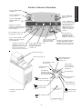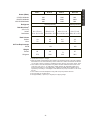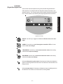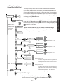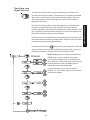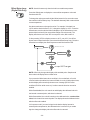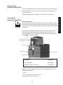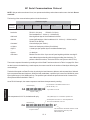
1
idealvac.com NESLAB R TE RTE Refrigerated Bath Thermo Manual P/N U00694 Rev. 07/13/05 (505)872-0037 idealvac.com Installation-OperationBasic Service No part of this publication may be reproduced or reprinted except for personal use without the prior permission of Thermo Electron. Visit our Web site at: http://www.thermo.com/tc Product Service Information, Applications Notes, MSDS Forms, e-mail. Voice Info: (800) 258-0830 Table of Contents Preface Compliance .............................................................................................................. 2 WEEE Compliance ................................................................................................... 2 Unpacking ................................................................................................................ 2 Warranty................................................................................................................... 2 After-sale Support .................................................................................................... 3 NES-care Extended Warranty Contract ................................................................... 3 Copyright ................................................................................................................. 3 Feedback ................................................................................................................. 3 Section I Safety Warnings .................................................................................................................. 4 Section II General Information Quick Reference Operating Procedures ................................................................. 6 Description ............................................................................................................... 7 Specifications ........................................................................................................... 7 Section III Installation and Operation Site ......................................................................................................................... 11 Electrical Requirements ......................................................................................... 12 Plumbing Requirements ........................................................................................ 14 Fluids ..................................................................................................................... 16 Filling Requirements .............................................................................................. 17 Controller (Digital One/Digital Plus) ...................................................................... 17 Start Up/Shut Down ................................................................................................ 19 Setup/Tuning Loop ................................................................................................ 21 Controller (Digital Plus) ......................................................................................... 22 Computer Setup Loop .......................................................................................... 24 Timer Setup Loop .................................................................................................. 25 Offset Setup Loop .................................................................................................. 26 Analog A I/O Port - Optional ................................................................................... 27 High Temperature Cutouts ..................................................................................... 28 Nitrogen Purge ....................................................................................................... 29 Accessories ............................................................................................................ 29 Section IV Basic Maintenance Reservoir Fluid ...................................................................................................... 33 Reservoir Cleaning ................................................................................................ 33 Algae ...................................................................................................................... 33 Condenser Cleaning .............................................................................................. 33 Internal Temperature Sensor (rtd1) Calibration .................................................... 34 External Temperature Sensor (rtd2) Calibration ................................................... 35 Optional Analog Port/Calibration - Optional .......................................................... 36 Section V Troubleshooting Error Codes ........................................................................................................... 37 External Sensor Connector ................................................................................... 38 Checklist................................................................................................................. 39 Service Assistance ................................................................................................. 40 PID Values .............................................................................................................. 40 BOM Decoder ........................................................................................................ 41 Displaying Software Version Number .................................................................... 41 Appendix A Fluids Appendix B NC Serial Communications Protocol Appendix C International Quick Reference Operating Procedures WARRANTY -1- Preface Compliance UL Listed to UL3101-1 (UL61010A-1) Certified to CSA C22.2 No. 1010.1 Complies with IEC/EN 61010-1 Products tested and found to be in compliance with the requirements defined in the EMC standards defined by 89/336/EEC as well as Low Voltage Directive (LVD) 73/23/EEC can be identified by the CE label on the rear of the unit. The testing has demonstrated compliance with the following directives: LVD, 73/23/EEC EN 610010-1:1993 EMC, 89/336/EEC EN 61326-1:1998 For any additional information, refer to the Letter of Compliance that shipped with the unit (Declaration of Conformity). WEEE Compliance This product is required to comply with the European Union’s Waste Electrical & Electronic Equipment (WEEE) Directive 2002/96/EC. It is marked with the following symbol: Thermo Electron has contracted with one or more recycling/disposal companies in each EU Member State, and this product should be disposed of or recycled through them. Further information on Thermo Electron’s compliance with these Directives, the recyclers in your country, and information on Thermo Electron products which may assist the detection of substances subject to the RoHS Directive are available at: www.thermo.com/WEEERoHS Unpacking Retain all cartons and packing material until the unit is operated and found to be in good condition. If the unit shows external or internal damage contact the transportation company and file a damage claim. Under ICC regulations, this is your responsibility. Warranty Units have a warranty against defective parts and workmanship for 24 months from date of shipment. See back page for more details. -2- After-sale Support Thermo Electron Corporation is committed to customer service both during and after the sale. If you have questions concerning the unit operation, contact our Sales Department. If your unit fails to operate properly, or if you have questions concerning spare parts or Service Contracts, contact our Service Department. Before calling, please obtain the following information: - unit BOM number_________________________________ - unit serial number ________________________________ - unit software version ______________________________ - voltage of power source ____________________________ The unit’s BOM number and serial number are printed on the name plate label located on the rear of the unit. See page 41 for instructions on how to decode your unit's BOM number. See page 41 for instructions on how to display the software version. S/N: 101039026 NES-care Extended Warranty Contract • Extend parts and labor coverage for an additional year. • Worry-free operation. • Control service costs. • Eliminate the need to generate repair orders. • No unexpected repair costs. Other contract options are available. Please contact Thermo for more information. Copyright © 2005 Thermo Electron Corp. 623-2087 All rights reserved. This document is for informational purposes only and is subject to change without notice. Feedback We appreciate any feedback you can give us on this manual. Please e-mail us at [email protected]. Be sure to include the manual part number and the revision date listed on the front cover. -3- Section I Safety Warnings Warnings are posted throughout the manual. These warnings are designated by an exclamation mark inside an equilateral triangle and text highlighted in bold. Read and follow these important instructions. Failure to observe these instructions can result in permanent damage to the unit, significant property damage, or personal injury or death. The lightning flash with arrow symbol, within an equilateral triangle, is intended to alert the user to the presence of non-insulated "dangerous voltage" within the unit's enclosure. The voltage may be of significant magnitude to constitute a risk of electrical shock. This label, engraved into the front of the tank lip, indicates the presence of hot surfaces. Make sure you read and understand all instructions and safety precautions listed in this manual before installing or operating your unit. If you have any questions concerning the operation of your unit or the information in this manual, contact our Sales Department. Performance of installation, operation, or maintenance procedures other than those described in this manual may result in a hazardous situation and may void the manufacturer's warranty. Transport the unit with care. Sudden jolts or drops can damage the refrigeration lines. The units weigh approximately: RTE 7, 60 pounds (27 kilograms); RTE 10, 68 pounds (31 kilograms); RTE 17, 71 pounds (32 kilograms); RTE 740, 87 pounds (39 kilograms). Units should be transported with equipment designed to lift these weights. Observe all warning labels. Never remove warning labels. Never operate damaged or leaking equipment. Never operate the unit without bath fluid in the bath. The user is responsible for the fluid used. Never use pure ethylene glycol as a bath fluid, the flash point of 100% ethylene glycol is 111°C. 100% ethylene glycol may produce flammable vapors that can be ignited by an open flame or an ignition source. When mixed with water, ethylene glycol is not flammable. Also, at high temperatures pure ethylene glycol may produce hazardous vapors. Always turn off the unit and disconnect the line cord from the power source before performing any service or maintenance procedures, or before moving the unit. Always empty the bath before moving the unit. Never operate equipment with damaged line cords. Refer service and repairs to a qualified technician. -4- Press to start/stop the unit. See page 17. Press to change the displayed value. See page 17. Indicates refrigeration system status. See page 17. Press to sequence through the three indicators and accept the displayed value. See page 17. NOTE: None of the three setpoint indicators are visible unless this key is pressed. Indicates the controller is displaying the setpoint. Press the arrow buttons to change the value. See page 18. Press to mute the alarm. See page 22. Digital Plus controller only. Press to select the temperature offset mode. See page 23. Digital Plus controller only. Press to select external sensor. See page 22. Digital Plus controller only. Indicates the controller is displaying the unit's low temperature alarm setpoint. Press the arrow buttons to change the value. See page 18. General Information Section II General Information Indicates heater status. See page 17. Press to select the serial communication mode. See page 22. Digital Plus controller only. Press to select the timer function. See page 23 Digital Plus controller only. Indicates the controller is displaying the high temperature alarm setpoint. Press the arrow buttons to change the value. See page 18. Controller. See page 17. Reservoir. See page 16. Optional External Sensor Connector. Digital Plus controller only. High Temperature Cutout. See page 28. Autorefill connection. See page 29. RS-232/RS-485 connections. See Appendix B. Digital Plus controller only. 1/8"OD Autorefill fluid connection. See page 29. Analog Output Connector. Digital Plus controller only. See page 27. Circuit Breaker(s). Power connection. See page 12. 1/8"OD N2 Nitrogen Purge. See page 29. 1/*4" MPT Pumping Condenser Access Panel. Supply Connection. See page 14. 1/4" MPT Pumping Return Connection. See page 14. See page 33. Drain. See page 14. -5- General Information Quick Reference Operating Procedures Installation Locate the unit on a sturdy work area. Ambient temperatures should be inside the range of +50°F to +104°F (+10°C to +40°C). The maximum operating relative humidity is 80%. Operation Before starting the unit, double-check all electrical and plumbing connections. Make sure the bath is properly filled with fluid. Never place the unit in a location where excessive heat, moisture, or corrosive materials are present. To start the unit, press The unit has an air-cooled refrigeration system. Air is drawn through the front panel and discharged through the rear panel. The unit must be positioned so the air intake and discharge are not impeded. A minimum clearance of 12 inches (30 centimeters) at the front and rear of the unit is necessary for adequate ventilation. Inadequate ventilation will reduce cooling capacity and, in extreme cases, can cause compressor failure. press . To turn the unit off again. The LED indicates the status of the heater. It illuminates to indicate the heater is on. The LED indicates the status of the refrigera- tion system. It illuminates to indicate the refrigeration system is removing heat from the cooling fluid. Temperature Adjustment Excessively dusty areas should be avoided and a periodic cleaning scheduleshould be instituted. To display the temperature setpoint, press The unit will retain its full rated capacity in ambient temperatures up to approximately +75°F (+24°C). on the controller. The indicator will illuminate and the display will flash the current setpoint value. To adjust the temperature setpoint, press the arrow buttons until the desired temperature setpoint is Make sure the voltage of the power source meets the specified voltage, ±10%. The pump connections are located at the rear of the pump box and are labelled and . These connections are angled upward so the recirculating fluid will drain back into the reservoir when the hoses are disconnected. Both connections are capped with stainless steel serrated plugs. indicated. Press again to confirm the change. The display will rapidly flash the new value for a short time and then return to the recirculating fluid temperature. Periodic Maintenance Periodically inspect the reservoir fluid. If cleaning is necessary, flush the reservoir with a cleaning fluid compatible with your application. The pump lines have ¼" MPT for mating with standard plumbing fittings. For your convenience stainless steel adapters, ¼" FPT to 3/8" O.D. serrated fitting, are provided. The reservoir fluid should be replaced periodically. Frequency depends on the operating environment and amount of usage. The bath work area has a high and low level marker to guide filling. The markers are 1 inch horizontal slits located in the center of the stainless steel baffle separating the work area and the pump assembly. The correct fluid level falls between these two markers. The unit will not start if the fluid level is below the lower slit. Before changing the reservoir fluid ensure it is at a safe handling temperature. Periodic vacuuming of the condenser fins is necessary. The frequency of cleaning depends on the operating environment. We recommend a monthly visual inspection of the condenser after initial installation. After several months, the cleaning frequency will be established. -6- The NESLAB RTE Refrigerated Bath/Circulators are designed to provide temperature control for applications requiring a fluid work area or pumping to an external system. Units consist of a non-CFC air-cooled refrigeration system, circulation pump, seamless stainless steel bath, work area cover, and a microprocessor temperature controller. Specifications1 RTE 7 2 Temperature Range RTE 10 -25°C to +150°C RTE 17 RTE 740 -22°C to +150°C -40°C to +200°C ±0.01°C Temperature Stability3 1100 Cooling Capacity4, 1000 B Heat Removal (Watts) 900 800 A 700 600 500 C 400 300 A=115/60 RTE-740 units B=230/50 RTE-740 units C=RTE-7, 10, 17 200 100 -40-30-20-10 0 10 20 30 40 50 60 70 80 90100 Temperature °C Pump Capacity4 Pressure Meters Feet 4.9 16 3.7 12 2.4 8 1.2 4 0.8 3 -7- 1.6 2.4 6 9 Flow 3.2 12 4.0 Gpm 15 Lpm General Information Description General Information Time to Temperature 115V/60 Hz units 230V/50 Hz units RTE-740 units -8- Heater (Watts) 115V/60 Hz Models 230V/50 Hz Models 100V/50-60Hz Models 800 2000 800 Bath Volume Gallons Liters RTE 740 1600 2000 1200 800 2000 800 R404a (8 ounces) 65/8 x 7¼ x 6 8¾x 9 3/8 x 6 8¾ x 9 3/8 x 9 65/8 x 7¼ x 6 16.8 x 18.3 x 15.2 22.4 x 23.9 x 15.2 22.4 x 23.9 x 22.9 16.8 x 18.3 x 15.2 1.9 7.2 2.6 9.8 Air Flow Requirements SCFM Weight5 Pounds Kilograms RTE 17 R134a (6 ounces) Refrigerant Bath Work Area5 (W x L x D) Inches Centimeters RTE 10 4.5 17.0 170 68 30.8 60 27.2 1.9 7.2 200 71 32.2 87 39.5 1. Specifications subject to change. 2. Baths are tested at temperatures below freezing with denatured alcohol. This fluid is HIGHLY flammable and is not recommended by Thermo. Above 80°C, baths are tested at with silicone oil. This fluid is known to release a formaldehyde vapor (which is carcinogenic) above 150°C. 3. 20°C ambient. 20°C bath temperature using water. Sea level. Measured at the center of the work area, work cover on, no external flow, stable ambient, full refrigeration (RTE-740 in Energy Saving Mode). For some applications, agitation and stability above ambient may be improved by connecting a small length of hose between the pump connections on the rear of the unit. 4. 20°C ambient. 20°C bath temperature using water. Pump fully loaded. Sea level. 5. See next page for unit dimensions. 6. Add approximately 3 pounds (1.4 kilograms) for shipping weight. -9- General Information RTE 7 General Information Unitl Dimensions (inches) C F 7 30° ½ /8 1 3¼ 15 / 8 17 / 8 105° A D E 1½ B Rear View Side View Unit Dimensions RTE 7 RTE 10 RTE 17 RTE 740 Dimension A 23 5/8 23 5/8 26 5/8 26 5/8 Dimension B 9 1/4 11 3/8 11 3/8 11 3/8 Dimension C 19 20 1/8 20 1/8 20 1/8 Dimension D 17 3/8 17 3/8 20 3/8 20 3/8 Dimension E 10 5/8 10 5/8 10 5/8 12 3/8 Crate Dimensions (D x W x H) 26½ x 18 x 33½ - 10 - Section III Installation and Operation Site Locate the unit on a sturdy work area. Ambient temperatures should be inside the range of +50°F to +104°F (+10°C to +40°C). The maximum operating relative humidity is 80%. The unit has an air-cooled refrigeration system. Air is drawn through the front panel and discharged through the rear panel. The unit must be positioned so the air intake and discharge are not impeded. A minimum clearance of 12 inches (30 centimeters) at the front and rear of the unit is necessary for adequate ventilation. Inadequate ventilation will reduce cooling capacity and, in extreme cases, can cause compressor failure. Excessively dusty areas should be avoided and a periodic cleaning schedule should be instituted (see Section IV, Condenser Cleaning). Using 20°C water as a bath fluid, 115/60 units will retain their full rated capacity in ambient temperatures up to +20°C. Reduce the cooling capacity approximately 15 watts for every 1°C above +20°C, to a maximum ambient temperature of +40°C. For 230/50 units, reduce the cooling capacity approximately 18 watts for every 1°C. Lower reductions in cooling capacity occur as the bath fluid temperature increases. - 11 - Installation and Operation Never place the unit in a location where excessive heat, moisture, or corrosive materials are present. Electrical Requirements Installation and Operation The unit construction provides protection against the risk of electrical shock by grounding appropriate metal parts. The protection may not function unless the power cord is connected to a properly grounded outlet. It is the user's responsibility to assure a proper ground connection is provided. We recommend the use of a dedicated outlet. Refer to the serial number label on the rear of the unit to identify the specific electrical requirements of your unit. Ensure the voltage of the power source meets the specified voltage, ±10%. The RTE-7 is not designed to be used beyond the voltage range or have momentary power interruptions. Install an “un-interruptible power supply” or a line loss detection method. All units are: Pollution Category 2 Overcurrent Protection II The following power options are available: Unit Amps1 Breaker Power Inlet RTE 7 115/60/1 100/50-60/1 230/50/1 12 12 12 15A 15A 15A IEC 320-C-13 IEC 320-C-13 IEC 320-C-19 RTE 10 115/60/1 100/50-60/1 230/50/1 12 12 12 15A 15A 15A IEC 320-C-13 IEC 320-C-13 IEC 320-C-19 RTE 17 115/60/1 100/50-60/1 230/50/1 16 16 12 20A 20A 15A IEC 320-C-19 IEC 320-C-19 IEC 320-C-19 RTE 740 115/60/1 100/50-60/1 230/50/1 16 16 12 20A 20A 15A IEC 320-C-19 IEC 320-C-19 IEC 320-C-19 1. Average Amp draw. - 12 - Unit Type1 Plug Type 115/60/1 15 NEMA 5-15 115/60/1 20 NEMA 5-20 100/50-60/1 15 NEMA 5-15 100/50-60/1 20 NEMA 5-20 230/50/1 All Country Specific 1. Power cord length, if supplied, is 2 meters. Power Cord Set 230 Volt, 50 Hertz units do not come with a power cord set. To select the proper power cord, follow these guidelines: The cord set must consist of a plug, cable and receptacle. If the unit is rated greater than 12 Amps, use a cord set rated for 20A. If the unit is rated less than 12 Amps, use a cord set rated for 15A. The cord set must be approved by local electrical authority or other acceptable agency. Ensure the plug is compatible with your local outlets and receptacles. - 13 - Installation and Operation Amperage Plumbing Requirements Ensure the unit is off before connecting tubing to the unit. To prevent damage to the plumbing lines, always support the fittings while installing/removing the pumping caps and lines. Hose Connections The pump connections are located at the rear of the pump box and are labelled Installation and Operation (pump outlet) and (pump inlet). These connections are bent upward so the recirculating fluid will drain back into the reservoir when the hoses are disconnected. Both connections are capped with stainless steel serrated plugs. The pump lines have ¼" MPT for mating with standard plumbing fittings. For your convenience stainless steel adapters, ¼" FPT to 3/8" O.D. serrated fitting, are provided. (To assure proper fit, they should be installed using 1½ turns of Teflon® tape around the threads.) Make sure all tubing connections are securely clamped. Avoid running tubing near radiators, hot water pipes, etc. If substantial lengths of tubing are necessary, insulation may be required to prevent loss of cooling capacity. Tubing and insulation are available from Thermo. Contact our Sales Department for more information (see Preface, After-sale Support). It is important to keep the distance between the unit and the external system as short as possible, and to use the largest diameter tubing practical. Tubing should be straight and without bends. If diameter reductions must be made, make them at the inlet and outlet of the external system, not at the unit. If substantial lengths of cooling lines are required, they should be pre-filled with bath fluid before connecting them to the unit. This will ensure that an adequate amount of fluid will be in the bath once it is in operation. Drain Ensure the bath fluid is at a safe handling temperature before draining the unit. The unit is equipped with a drain located at the back of the unit labelled . To drain the reservoir attach a hose to the barb and loosen the fitting. The fitting has a stop to prevent it from coming off. Pumping The pump is designed to deliver a flow of 15 liters per minute (4 gallons per minute) at 0 feet head. To prevent external circulation, the pump inlet and outlet lines on the rear of the unit are capped. The caps must be removed when external circulation is required. To properly secure external hose connections to the unit, wrap Teflon® tape around the pipe line threads before installation. Once the hose connections are made, the hoses must be properly plumbed to an external system. It is important the bath is not in operation until all plumbing is complete. - 14 - Circulating to an open container Levelling Device Outlet Inlet Open Container A stainless steel leveling device is available to aid circulation to an open vessel. Contact our Sales Department for more information (see Preface). Support the leveling device over the open container with a ringstand. Stagger the tubes in the leveling device so one tube is submerged in the vessel fluid, and the other tube is level with the fluid surface. Connect the deeper tube to the pump outlet and the shorter tube to the pump inlet. Adjust the flow rate using the accessory flow control valve connected to the pump outlet, or by partially restricting the outlet tubing. When properly adjusted, the pump inlet will draw an occasional air bubble to prevent over flow, and the pump outlet will force fluid through the submerged tube to prevent aeration of the vessel. To avoid siphoning the bath work area when the unit is shut off, lift the leveling device out of the vessel and above the level of the unit. Circulating through two closed-loops Pump Box System #1 Bath Work Area System #2 Bath (Top View) The pump can be used to circulate through two closed-loop systems. Connect the shortest practical length of flexible tubing from the pump outlet to the inlet of external system #1. Connect the outlet of system #1 directly into the bath work area. Connect tubing from the bath work area to the inlet of system #2. Connect the outlet of system #2 to the pump inlet. - 15 - Installation and Operation Bath (Rear View) Fluids The user is always responsible for the fluid used. Never use flammable or corrosive fluids with this unit. The use of chlorine or sodium hypochlorite in the baths will cause pitting that could leave to failure of the refrigeration system. Installation and Operation Handling and disposal of liquids other than water should be done in accordance with the fluid manufacturers specification and/or the MSDS for the fluid used. For fluid selection consider application requirements, operating temperature range, material compatibility, safety concerns, and environmental issues. Wetted materials of bath include; 316 and 304 Stainless steels, Ryton® (PPS), Teflon®(PTFE) and Ethlyene-Propylene rubber (EPDM). Deionized (up to 18 Meg-ohm/cm) and distilled water are recommended to control corrosion and algae bloom. See Water Quality Standards and Recommendation in Appendix A. Ethylene glycol, propylene glycol, silicone oil, and filtered water are acceptable fluids. NOTE: Kinematic viscosity of the selected fluid should not exceed 50 centistokes at the lowest operating temperature. Please call Thermo customer service to discuss high and low temperature fluid selections. However, we will often refer you to chemical companies specializing in heat transfer fluids. Filling Requirements Ensure the drain on the back of the unit is closed before filling the unit. The bath work area has a high and low level marker to guide filling. The markers are 1 inch horizontal slits located in the center of the stainless steel baffle separating the work area and the pump assembly. The correct fluid level falls between these two markers. NOTE: The unit is equipped with a reservoir level float switch. The switch prevents the unit from starting if the fluid is below the lower slit. When pumping to an external system, keep extra fluid on hand to maintain the proper level in both the circulating lines and the external system. Avoid overfilling, fluids expand when heated. - 16 - Controller (Digital One/Digital Plus) The controller controls temperature using a Proportional-Integral-Derivative (PID) algorithm. It is designed with self-diagnostic features and easy to use operator interface. Two controller options are available: Digital One and Digital Plus. The information on the following two pages applies to both controllers. Installation and Operation Digital One Controller ON/OFF. Use this key to toggle the unit on or off and to clear error messages. SCROLL. Use this key to scroll through the controller's LEDs. It is also used to save new changes. Yes No YES/ARROW. Use this key to increment numerical values when setting values and to accept new settings. NO/ARROW. Use this key to decrement numerical values when setting values and to abort new settings. Indicates refrigeration system status. It illuminates to indicate the refrigeration system is removing heat from the bath fluid. The indicator is off when heat is not being removed. Indicates heater status. It illuminates to indicate the heater is adding heat from the bath fluid. The indicator is off when heat is not being added. - 17 - NOTE: The following indications are not visible until is depressed. Setpoint. Indicates the controller is displaying the current setpoint. Installation and Operation Low Temperature Alarm. Indicates the controller is displaying the current low temperature alarm. High Temperature Alarm. Indicates the controller is displaying the current high temperature alarm. To adjust the displayed value use the arrow buttons. Pressing an arrow button will cause the display to stop flashing and to indicate the new setpoint value. Save the change by pressing SCROLL. The new setpoint value will rapidly flash for two cycles and then the controller will return to the reservoir fluid temperature display. If SCROLL is not pressed within 60 seconds the change will time out and revert to the original setpoint. The controller will automatically return to the reservoir fluid temperature display. NOTE: You can not adjust the setpoint closer than 0.1°C of either temperature limit, and you can not adjust either temperature limit within 0.1°C of the setpoint. Trying to do so will cause the indicator to flash and, on Digital Plus controllers, the alarm to beep. On units with the Digital Plus controller, pressing the Mute button prior to pressing SCROLL will abort any changes and return to the reservoir fluid temperature display. - 18 - Start Up/Shut Down (Digital One/Digital Plus) Pre-Start Before starting the unit, recheck all electrical and plumbing connections. Ensure the bath reservoir is properly filled. The unit will not start if the reservoir fluid level is below the lower horizontal slit. The unit can be configured for automatic restart. If the unit shuts down as a result of a losing power, once power is restored the unit will restart. See Setup/Tuning Loop on page 21 to enable this feature. Starting Press . The controller does a self-test (sequences through the LEDs, and Digital Plus units momentarily sound the alarm), then quickly displays the setpoint before displaying the reservoir fluid temperature. The pump starts and, after a 30 second delay, the refrigeration comes on. The RTE-740 refrigeration system is designed to start with the pump. NOTE: If the unit's recirculating fluid is outside either temperature limit, the unit will start but the appropriate indicator will flash until the fluid is within the limit. Full Range Cooling Setpoint If refrigeration is needed for operation above 50°C, turn on the Full Range Cooling Mode. See Setup/Tuning Loop on page 21 to enable this feature. To display/change the setpoint press until illuminates. The display will flash the current setpoint value. Use the arrow buttons to change the value. The controller will not allow you to enter a setpoint closer than 0.1°C of either temperature alarm setting, see next page. Attempting to causes the indicator to flash and, on Digital Plus controllers, sounds the alarm. Once an arrow button is depressed starts to flash. If an arrow button is not pressed within 10 seconds the display will return to the reservoir temperature. On units with the Digital Plus controller, pressing Mute prior to pressing SCROLL will abort any change and return you to the fluid temperature display. Once the desired setpoint is displayed, press again to confirm the change. The display will rapidly flash the new value twice and then return to the recirculating fluid temperature. If the new value is not confirmed within 60 seconds the display will return to the fluid temperature and ignore any change. - 19 - Installation and Operation Controller Low Temp Alarm To display/change the low temperature alarm setting press until illuminates. The display will flash the current limit value. Use the arrow buttons to change the value. You can not set the alarm closer than 0.1°C below the setpoint. Attempting to causes the indicator to flash and, on Digital Plus controllers, sounds the alarm. Installation and Operation On units with the Digital Plus controller, pressing Mute prior to pressing SCROLL will abort any change and return you to the fluid temperature display. Once an arrow button is depressed starts to flash. If an arrow button is not pressed within 10 seconds the display will return to the current reservoir temperature. Once the desired setting is displayed, press again to confirm the change. The display will rapidly flash the new value twice and then return to the recirculating fluid temperature. If the new value is not confirmed within 60 seconds the display will return to the fluid temperature and ignore any change. High Temp Alarm To display/change the high temperature alarm setting press until illuminates. The display will flash the current setting value. Use an the arrow buttons to change the value. You can not set the alarm closer than 0.1°C above the setpoint. Attempting to causes the indicator to flash and, on Digital Plus controllers, sounds the alarm. On units with the Digital Plus controller, pressing Mute prior to pressing SCROLL will abort any change and return you to the fluid temperature display. Once an arrow button is depressed starts to flash. If an arrow button is not pressed within 10 seconds the display will return to the current reservoir temperature. Once the desired limit is displayed, press again to confirm the change. The display will rapidly flash the new value twice and then return to the recirculating fluid temperature. If the new value is not confirmed within 60 seconds the display will return to the fluid temperature and ignore any change. Stopping To turn the unit off, press . The pump will stop and the refrigeration will shut down. NOTE: The RTE-740 refrigeration system is designed to shut down thirty seconds after the pump. Thermo recommends waiting a minute before restarting the unit. - 20 - Setup/Tuning Loop (Digital One/Digital Plus) The Setup/Tuning Loop is used to tune the controller's PID parameters (CooL HEAt); enable/disable auto restart (AStrt); determine how the unit will react when a fault occurs (FAUlt) — either shut down (on) or continue to run (oFF); to configure the temperature display to indicate to a tenth or a hundredth of a degree (rES); and to enable/disable full range cooling (FrC) and energy saving (ESAuE) modes. HOLD No XX.X NOTE: For RTE-7, 10, and 17 units the COOL PID display CooL CooL only appears if the Energy Saving No mode is enabled, see below. Yes To enter the loop you must be displaying the reservoir fluid temperature, press and hold and then press . The display will indicate tunE. Use the arrow keys to sequence through the loop and to change a display. Use to confirm any changes. Thermo recommends that only a qualified technician change PID parameters. Incorrect PID values will hamper unit performance. See page 40 for factory preset PID values. HEAt No AStrt on Yes oFF No on Yes oFF No AStrt Yes Factory preset = off No FAULt FAULt Yes Factory preset = off No 0.1 rES Yes rES Yes 0.01 No Factory preset = 0.1 No on FrC No on ESAuE RTE-7, 10, 17 only Yes Full range cooling mode allows the refrigeration to operate throughout the entire temperature range. If off, refrigeration is available only below 50°C. Yes No No Factory preset = off The Energy Saving mode is primarily designed for applications running under a stable load. Enabling the mode saves energy by reducing the unit’s heater power requirements. This can result in substantial energy savings over the life of the unit. StorE Yes Factory preset = off Accept All Changes Changes made in the Tuning/Setup Loop take affect when Yes is pressed at the StorE prompt. Pressing No at the prompt aborts all changes. - 21 - Installation and Operation tunE No Controller (Digital Plus Only) Alarm. If the alarm sounds, use this button to toggle the alarm off and on. If the cause of the alarm is cleared but then reoccurs, the alarm will sound again. Installation and Operation Mute The button is also used to abort changes to the setpoint and temperature alarms. It is also used to abort changes when configuring the unit for external probe, serial communication, timer operation, or offset mode. NOTE: Pressing and holding any of the following buttons for five seconds takes you to their calibration or setup loop. Sensor External Probe. Pressing the Sensor button displays the external probe temperature and lights the LED indicating that the bath is monitoring and controlling to this temperature. The unit will continue to monitor the internal bath temperature to ensure the bath is running in a safe operating mode. NOTE: If there is no sensor attached (or the circuit is open), or serial communications is enabled, the button will flash, and the alarm will beep three times. The display will momentarily show an error message and then return to the reservoir fluid temperature. NOTE: The temperature display may drift for up to 10-15 seconds when transitioning between temperature sensors. This is normal operation. Computer Serial Communication. Pressing Computer enables/disables the serial communications mode of operation. In this mode all changes to the setpoint, alarm limits, etc. must now be sent by a remote device using RS-232 or RS-485 protocols. You can still view all settings locally but cannot alter them. Once enabled, the Computer LED will flash when sending and receiving signals. See Appendix B for additional information. You can also turn the unit off by pressing but the unit will remain in the serial communication mode. To restart, send another start command. NOTE: If the unit is shut down in the serial communication mode and you need to start the unit using the local controller, simultaneously depress and hold both arrow keys for approximately 10 seconds. The display will then show the internal probe temperature, and the alarm will sound. Press the LED Computer and turn off the LED and disable serial communications. Turn the controller off using . You can now start and operate the unit with the keypad. - 22 - Timer. Pressing the Timer button enables/disables the Timer function of the bath. You can define the current time, a turn-on time, and a turn-off time. Timer To setup the bath for timer operation see Timer Setup Loop on page 25. If the bath is turned off using with the timer mode enabled, the Timer LED NOTE: Enabling serial communications; time-on not defined; time-off not defined; or clock not set, causes an error condition and disables the TIMER mode. In this case the button will flash, the unit will beep three times, and the display will momentarily show an error message. If a power disruption occurs, the timer mode is disabled. The Timer Setup Loop will have to be used to restore the settings. Offset Temperature Offset Mode. Pressing the Offset button, with the bath on, enable/disables the temperature offset mode. This mode changes the temperature displayed on the bath a user defined amount. The LED will be lit when this mode is enabled indicating that the temperature displayed is an offset value. NOTE: The temperature offset only affects the displayed value when the offset mode is enabled, the other setpoint values still dictate unit performance. To setup the bath for offset mode operation see Offset Setup Loop on page 26. If you press the Offset button when an offset is 0 or not defined, or if serial communications is enabled, the button will flash, the unit will beep three times, and the display will momentarily show an error message (Er53 for offset undefined, Er54 for serial comm on). In either case the function can not be enabled. NOTE: Use this feature only when the bath is at a stable temperature. In either local or Computer mode with offset disabled, the unit controls to and displays the calibrated value for the internal or external probe, whichever is selected. In either local or Computer mode with offset enabled, the unit still controls to the calibrated value, not the offset value, for the internal or external probe. The display shows the calibrated value with the offset value added. In Computer mode if you send a signal to the bath to display internal or external probe temperatures, the calibrated value is returned. If you send a signal to change the display value the offset value is returned. - 23 - Installation and Operation will go out and the timer mode will be disabled. With the bath off, you have to press the Timer button to enable the timer mode and light the LED. Computer Setup Loop (Digital Plus Only) NOTE: The Computer Setup Loop is not available if the serial communications mode is enabled. Review/change the settings before entering the mode. The Computer Setup Loop is used to set the serial communications protocol parameters. With the bath on, press and hold the Computer button for five seconds. The controller will display SErL. Press the arrow buttons to toggle between 232 and 485. Press the Computer button to hold the protocol and advance you through the loop to adjust the remaining parameters. Press the arrow buttons to adjust any parameter. When StorE is displayed press YES to accept any new values, NO to abort them. Installation and Operation Computer If the Computer button is not pressed for 60 seconds the function will time-out and the changes will not be saved. Pressing the Mute button will also exit the Computer Setup Loop and return you to the reservoir fluid temperature display. Once enabled, the Computer LED will flash when sending and receiving signals. See Appendix B for additional serial communication information. Hold for 5 seconds XX.X Computer 232 Yes Factory preset = RS232 485 SErL A In No A In = Analog In, Optional See page 27. Computer 19200 9600 4800 2400 1200 600 300 bAud Computer Yes No Yes 1 to 100 Addr No Computer No StorE Yes Accept All Changes - 24 - Factory preset = 19200 Factory preset = 1 (RS-485 only) Timer Setup Loop (Digital Plus Only) Timer To set the timer, with the bath on, press and hold the Timer button for five seconds to access the controller's Timer Setup Loop. The display will indicate diSP. Use the arrow buttons to select the desired clock display. Press the Timer button and the controller will display cloc. Use the arrow buttons to display the correct time. If the Timer button is not pressed for 60 seconds the function will time-out and the changes will not be saved. Pressing the Mute will also exit the Timer Setup Loop and return you to the temperature display. If the bath is turned off using with the timer mode enabled, the Timer LED will go out and the timer mode will be disabled. With the bath off, you have to press the Timer button to enable the timer mode and light the LED. NOTE: Enabling serial communications disables the TIMER mode. If an error condition exists: serial communications enabled; time-on not defined; timeoff not defined; or clock not set, the unit will beep and will not enable the function. The display will then indicate the reservoir fluid temperature. If a power disruption occurs, the timer mode is disabled. The Timer Setup Loop will have to be used to restore the settings. - 25 - Installation and Operation Press the Timer button and the controller will display t-On. Press the arrow buttons to set the desired turn-on time. Press the Timer button and the controller will display t-OFF. Press the arrow buttons to set the desired turn-off time. Pressing the Timer button after entering the clock time will display StorE. Press YES to accept the values, NO to abort them. Offset Setup Loop (Digital Plus Only) NOTE: Use this feature only when the bath is at a stable temperature. Press the Offset button to display the current offset temperature value and illuminate the LED. Installation and Operation Offset To change the value press and hold the Offset button for five seconds to enter the controller's Offset Setup Loop. The bath will alternately flash oFSEt with the current temperature. Use the arrow buttons to change the value. For example, if the bath is at +40°C and the desired offset is +5°C, change the display to +45°C. Press the Offset button once the desired offset is displayed. (If the Offset button is not pressed the function will time-out and the change will not be saved.) The display will show StorE. Press YES to accept the value, NO to abort it. If, after pressing YES, the display returns to +40°C, not +45°C, the Offset button was not depressed when you entered the Offset Setup Loop. Press the Offset button to display the offset temperature and illuminate the LED. Hold for 5 seconds XX.X Offset Yes OFSEt xxx.x No Offset No StorE Yes Accept All Changes NOTE: Offset only changes the display of the enabled probe. Setpoint and alarm values will display the non-offset value. If you press the Offset button when an offset is 0 or not defined, or if serial communications is enabled, the button will flash, the unit will beep three times, and the display will momentarily show an error message (Er53 for offset undefined, Er54 for serial comm on). In either case the function can not be enabled. With offset disabled, the unit controls to and displays the calibrated value for the internal or external probe, whichever is selected. With offset enabled, the unit still controls to the calibrated value, not the offset value, for the internal or external probe. The display shows the calibrated value with the offset value added. In Computer mode if you send a signal to the bath to display internal or external probe temperatures, the calibrated value is returned. If you send a signal to change the display value the offset value is returned. - 26 - Analog Port - Optional (Digital Plus Only) A I/O Analog Port The 15-pin female receptacle located on the rear of the controller is used for optional analog interface. Contact Ratings, Pins 1, 2, and 3 Maximum Voltage = 30 V AC/DC Maximum Current = 1 Amps @ 30 V 15 14 13 12 11 10 9 8 765 43 2 1 Minimum permissible load 10uA, 10mVDC Pin # Function 1 Status relay NO. Status relay pins 1 and 3 close on start up, and open on stop and all errors. 2 Status relay NC. Status relay pins 2 and 3 open on start up, and close on stop and all errors. 3 Status relay common 4-5 Not used 6 Analog Ground. The analog ground is physically separated from the power ground throughout the unit. To prevent offsets that result from ground currents, the analog and power grounds are only connected at the unit's power supply. Analog ground should only be used as a reference pin. 7 Temp out. The fluid temperature, as measured by the enabled sensor, can be read at this pin. The temperature scale is 10mV/°C, referenced to analog ground, pin 6 (example: +150mV = +15.0°C). 8 Not used 9 Digital output ground, reference for pin 14. Digital output ground should only be used as a reference pin. 10-13 Not used 14 Digital output +5VDC at 15mA max. 70mA max inrush current. This power supply energizes on start up and de-energizes on stop and all errors. 15 Setpoint in. The temperature setpoint can be controlled by applying a known voltage to this pin. The temperature scale is 10mV/°C, referenced to analog ground, pin 6 (example: +230mV = +23.0°C). The analog output requires calibration, see page 36. - 27 - Installation and Operation The analog signal is setup using the unit's Computer Setup Loop. With the bath on, press and hold the Computer button for five seconds. The controller will display SErL. If needed, press the arrow buttons to toggle between 232, 485, and A In. With A In displayed, press the Computer button again until StorE is displayed, press YES. Use the Computer button to enable/disable the analog signal. The button will flash when A in is enabled. High Temperature Cutouts (Digital One/Digital Plus) Installation and Operation Adjustable High Temperature Cutout To protect your application, the adjustable High Temperature Cutout ensures the heater will not exceed temperatures that can cause serious damage to your unit. A single temperature sensor is located in the bath fluid. A High Temperature fault occurs when the temperature of the sensor exceeds the set temperature limit. The safety has a range of 0°C to 230±20°C. In the event of a fault the unit will shut down and the controller will display HtC. The cause of the fault must be identified and corrected before the unit can be manually restarted. The cutout is not preset and must be adjusted during initial installation. To set the cutout, locate the small black adjustment dial on the rear of the controller. Turn the dial fully clockwise and turn the power switch off then back on. Start the unit. Adjust the setpoint for a few degrees higher than the highest desired fluid temperature and allow the bath to stabilize at the temperature setpoint. Turn the dial counterclockwise until you hear a click and the unit shuts down. Before you can restart the bath it has to cool down a few degrees. Then, without moving the adjustment dial, turn the power switch off then back on. NOTE: We recommend rechecking operation if the unit is moved. High Temperature Cutout N2 Nitrogen Purge Non-Adjustable High Temperature Cutout For added safety, the unit also has a non-adjustable High Temperature Cutout. With fluid in the bath, it is set to trip at 225°C ±8°C. If the bath is empty, the cutout has a typical trip point of 300°C. The heater temperature can continue to rise after the cutout trips up to approximately 314°C. There will be no indication the High Temperature Cutout activated other than an audible click. The unit will continue to run but the heater will no longer operate. Service will be required. - 28 - Nitrogen Purge (Digital One/Digital Plus) Units are equipped with nitrogen purge line designed to accept a constant flow of dry nitrogen into the reservoir. The nitrogen blankets the cooling fluid reducing fluid evaporation. Connect your nitrogen line to the N2 1/8" OD tube on the rear of the unit. Autorefill Accessory The autorefill accessory attaches to the rear of the bath. The autorefill provides makeup water to replace bath fluid lost to evaporation, etc. It will require a tap water source. A reservoir level float switch and logic/signal are already installed in the bath. When tap water is available, the bath is turned on, and the fluid reaches the lower 1 inch horizontal level indicator located in the reservoir the autorefill begins filling the bath. The autorefill shuts off when the fluid reaches the upper indicator, or if the bath is turned off. Autorefill Control Cable Attachment Cap Tube Tap Water Inlet Power Supply Inlet Autorefill Module Description Part Number 100-115V/50/60Hz 611012000001 200-240V/50/60Hz, No line cord 611028000001 NOTE: Power the Autorefill Accessory with an AC Adapter that is UL Listed with the following ratings: - Class 2 - Input rated 100-240 VAC, 47-63 Hz, 0.4A - Output rated 12VDC, 1.25A Max. - 29 - Installation and Operation Accessories (Digital One/Digital Plus) Installation and Operation Reservoir Overflow Device The overflow device is designed to act as an automatic drain for the unit's reservoir. The assembly is stainless steel with the exception of the drain fitting which is Ryton®. The unit can still be drained as normal, but if the level reaches the middle of the tee it will begin to overflow out the bent tube. •Drain the unit's reservoir. •Remove and discard the stop screw from the bottom of the unit's drain housing. •Remove the unit's drain fitting. Vertical Tube •Thread the overflow assembly into the drain housing. (You can remove the vertical tube assembly from the Swagelok® fitting if there is a clearance issue.) •After threading the overflow assembly in as far as it goes, loosen it back out until the Swagelok® fitting is at the top. Swagelok® Fitting Drain Fitting (Install •Install one of the two supplied 4-40 x ¼” phillips head screws into the bottom of the drain housing where the stop screw use to be. (Make sure this screw is tight so that the assembly doesn’t turn and drain the tank.) finger tight) Drain Housing Overflow Assembly •Reinstall the vertical tube assembly into the Swagelok® if it was removed. •Install the drain fitting into the end of the new assembly - finger tight. •Install the other supplied 4-40 x ¼"phillips head screw into the bottom of the overflow assembly. (This prevents the drain fitting from falling off the unit.) Description Part Number RTE 7 and RTE 10 overflow device 126000000044 RTE 17 overflow device 126000000045 RTE 740 overflow device 126000000049 - 30 - The following accessories are also available from Thermo: Stainless Steel Test Tube Racks Unit Test Tubes (maximum) Size (mm) Part Number 49 13 126000000040 RTE 7 25 18 126000000041 RTE 10 72 13 126000000042 RTE 10 42 18 126000000043 RTE 17 72 13 126000000042 RTE 17 42 18 126000000043 RTE 740 49 13 126000000040 RTE 740 25 18 126000000041 External Sensors (Digital Plus only) Description Part Number 6"L X .187"DIA, 6' Lead, Stainless Steel probe 058520 18"L X .187"DIA, 6' Lead, Stainless Steel probe 058521 1.5"L X .187"DIA, 6' Lead, Stainless Steel probe 058522 1.5"L X .062"DIA, 6' Lead, Stainless Steel probe 058523 6"L X .187"DIA, 6' Lead, Teflon® probe 058524 6"L X .187"DIA, 15' Lead, Stainless Steel probe 126000000025 6"L X .187"DIA, 20' Lead, Stainless Steel probe 126000000029 6"L X .187"DIA, 30' Lead, Stainless Steel probe 126000000024 1.5"L X .187"DIA, 30' Lead, Stainless Steel probe 126000000033 GFCI* Breaker Line Cords (115V 60Hz units only) Unit Description Part Number 15 Amp Units 125V/15A 4-6MA 126000000050 20 Amp Units 125V/20A 4-6MA 126000000051 RS-232/485 Communication Cables (Digital Plus only) Description Part Number 10' Cable Assembly 083258 *Ground Fault Current Interrupter. An electrical safety device which opens a circuit upon observation of electricity leaking to ground through an undefined path, most likely a human being. GFCI receptacles are required by the NEC in many locations. - 31 - Installation and Operation RTE 7 Accessories (Digital Plus Only) Installation and Operation RPC Remote Box An RPC can control the bath from a remote location. It mirrors the controller displays; and has the ability to store and run up to 16 programs. It operates by sending and receiving information by RS-485 serial communication. It attaches to the unit by an RS-485 cable with 9-pin D subminature connectors. The remote can be mounted to the wall with an included wall bracket, or it can be used on a desk top with the wall bracket removed. MENU HEAT COOL 120.0°C SETPOINT BATH ON Typical RPC Display Description Part Number RPC 100-115V/50/60Hz/1Ø (with NEMA 5-15P type plug) 604012000401 RPC 100-240V/50/60Hz/1Ø (requires country specific line cord, not included) 604028000401 10' Cable Assembly (included) 083258 25' Cable Assembly 426000000029 50' Cable Assembly 426000000030 75' Cable Assembly 426000000031 100' Cable Assembly 426000000032 200' Cable Assembly 426000000033 NOTE: Power the RPC with an AC Adapter that is UL Listed with the following ratings: - Class 2 - Input rated 100-240 VAC, 47-63 Hz, 0.4A - Output rated 12VDC, 1.25A Max. - 32 - Section IV Basic Maintenance To avoid electrical shock, disconnect the mains cord prior to removing any access panels or covers. Service Contracts Thermo offers on-site Service Contracts designed to provide extended life and minimal down-time for your unit. For more information, contact our Service Department (see Preface, After-sale Support). Reservoir Fluid Periodically inspect the reservoir fluid. If cleaning is necessary, flush the reservoir with a cleaning fluid compatible with your application. The reservoir fluid should be replaced periodically. Frequency depends on the operating environment and time of usage. Before changing the cooling fluid ensure it is at a safe handling temperature. Reservoir Cleaning Algae To restrict the growth of algae in the bath, we recommend that all circulation lines be opaque. This will eliminate the entrance of light required for the growth of most common algae. We recommend the use of Chloramine-T, 1 gram per 3½ liters. Condenser Cleaning For proper operation, the unit needs to pull substantial amounts of air through a condenser. A build up of dust or debris on the fins of the condenser will lead to a loss of cooling capacity. Periodic vacuuming of the condenser is necessary. To access the condenser the front grille must be removed. The unit must be turned off before the front panel is removed. All units have a one-piece condenser grille assembly held on by spring clips. Carefully pull forward on the bottom of the panel to remove it. The cleaning frequency depends on the operating environment. After initial installation, we recommend a monthly visual inspection of the condenser. After several months, the cleaning frequency will be established. - 33 - Maintenance Routine cleaning can be achieved by simply sponging down the seamless stainless steel tank with tap water. (Dish washing detergent may be used but the tank must be thoroughly rinsed.) Internal Temperature Sensor (rdt1) Calibration Should the bath fluid temperature display disagree with your calibrated reference thermometer, the internal temperature sensor (rtd1) may need calibration. Press and Hold XX.X No Do not pick calibration points that are outside the safe operating limits of the fluid in your application. For example with water, 90°C and 5°C would be typical calibration points. Yes No No Release NOTE: If it is more convenient, the low-end calibration can be performed before doing the high-end. CAL Yes rtd1 Yes r1 H Yes r1 H No No Maintenance r1 L Yes r1 L No rdt3 No A in rtd3 is used to calibrate the refrigeration system, contact Thermo. Optional Display Run the bath to a suitable highend calibration point. Place a No calibrated reference thermometer in the bath. Ensure the fluid 200.0 Yes temperature is stabilized. Press Yes and hold the NO button and then press the YES button three No times. Release the NO button. -40.0 The controller will display CAL. Yes Yes Press YES and the controller will display rdt1. Press YES again and the controller will display r1 H. Press YES again and the controller will alternately flash r1 H and the current probe temperature. Use the arrow buttons to adjust the temperature to match the reference thermometer. No AoUt Optional Display No No StorE Yes Accept All Changes Press the SCROLL and NO buttons as shown until StorE is displayed, press YES to accept the new value, press No to abort it. Repeat for the low-end temperature. Run the bath to a suitable low-end calibration point. At the r1 L display use the arrow buttons to adjust the temperature to match a calibrated reference thermometer. Press the SCROLL and NO buttons as shown until StorE is displayed, press YES to accept the new value, press NO to abort it. NOTE: Both the high and low temperatures must be entered for a valid calibration. If power is lost before the procedure is complete, critical data needed for the calculation of calibration parameters will be lost. After pressing the YES button at the StorE prompt wait several seconds before proceeding to ensure that a bad calibration message does not appear. Premature use of the keypad after pressing the YES button may cancel the bad calibration error message. - 34 - External Temperature Sensor (rtd2) Calibration (Digital Plus Only) When using any external sensor (rtd2) for the first time, Thermo recommends a calibration. This calibration will only affect the temperature read by the external sensor. Do not pick calibration points that are outside the safe operating limits of the fluid in your application. For example with water, 90°C and 5°C would be typical calibration points. XX.X NOTE: If it is more convenient, the lowend calibration can be performed before doing the high-end. Hold for 5 seconds Sensor No rtd2 Yes r2 H Yes r2 H Yes 200.0 Yes No No No Yes r2 L Yes -40.0 Yes No No StorE Yes Accept All Changes Press the SCROLL and NO buttons until StorE is displayed, pressing YES accepts the new value. Repeat for the low-end temperature. Run the bath to a suitable low-end calibration point. At the r2 L display use the arrow buttons to adjust the temperature to match a calibrated reference thermometer. Pressing the SCROLL button after the low calibration will display StorE, pressing YES accepts the new value. If the SCROLL button is not pressed for 60 seconds the function will time-out and the changes will not be saved. Pressing Mute will also exit the calibration and return you to the reservoir fluid temperature display. NOTE: Both the high and low temperatures must be entered for a valid calibration. If power is lost before the procedure is complete, critical data needed for the calculation of calibration parameters will be lost. After pressing the YES button at the StorE prompt wait several seconds before proceeding to ensure that a bad calibration message does not appear. Premature use of the keypad after pressing the YES button may cancel the bad calibration error message. - 35 - Maintenance r2 L Run the bath to a suitable high-end calibration point. Place the sensor and a calibrated reference thermometer in the bath. Ensure the fluid temperature is stabilized. Press and hold the Sensor button for five seconds. The controller will display rtd2. Press YES and the controller will display r2 H. Press YES and the display will alternately flash r2 H and the current probe temperature. Use the arrow buttons to adjust the temperature to match the reference thermometer. Optional Analog Port/ Calibration (Digital Plus Only) Press and Hold XX.X The analog signal is setup using the unit's Computer Setup Loop. With the bath on, press and hold the Computer button for five seconds. The controller will display SErL. If needed, press the arrow buttons to toggle between 232, 485, and A In. With A In displayed, press the Computer button again until StorE is displayed, press YES. The Computer button will flash when A in is enabled. Use the Computer button to enable/disable the analog signal. No Yes No No Release The analog input and output are calibrated at the factory. If you need to recalibrate follow the diagram until the display indicates A in. CAL Yes Pressing YES at the A in display and the display will indicate A iH. Press YES and the display will alternate between A iH and some value. Apply 2.5V to the analog input pin 15, see page 27 (analog ground is pin 6). Measure the precise value with a voltmeter. rtd1 No rdt3 Change the value on the bath display to match the voltmeter reading. Maintenance No A in Yes No A iH Yes A iH Yes A iL Yes No Press SCROLL to check your value and then press SCROLL again to display A iL. No No AoUt Yes No A iL A oH Yes x.xxxx A oH x.xxxx Yes No Yes No No No Yes No x.xxxx A oL x.xxxx No Factory A iH = A iL = A oH = A oL = StorE Yes Yes preset values: 2.5000 0.0000 2.5000 -.5000 Accept All Changes If desired, repeat the procedure for A iL. Apply 0V to pin 15. Measure the voltage and change the displayed value to match it Pressing YES at the AoUt display and the display will indicate A oH. Press YES and the display will alternate between A oH and 2.5000, the bath will set the Temp Out pin 7 output voltage to approximately 2.5V. Measure the voltage and change the displayed value to match it. Press SCROLL to check your value and then press SCROLL again to display A oL. If desired, repeat the procedure for A oL. The display will alternate between A oH and -.5000, the bath will set the Temp Out pin 7 output voltage to approximately -0.5V. Measure the voltage and change the value to match the meter. At the StorE display press YES to save the calibration, press No to abort it. NOTE: If error code Er16 appears you will need to recalibrate. - 36 - Section V Troubleshooting Error Codes On Start Up: ROM checksum. Check with Thermo Test failure. Locks up the program Display board failure. Clears when display board is fixed Critical checksum failure. Check with Thermo Operational Errors: Asynchronous communication error, check serial interface parameters Bad calibration data entered using Calibration Loop. Redo calibration Unusual Hardware Conditions These errors will flash on the display and cannot be cleared. These are internal controller problems. through - Interrupt errors during runtime Synchronous communication error BOM invalid. Contact Thermo Error Display Indication Low temp setpoint warning/fault, see page 21 Low level warning, fluid below safe operating level High temp setpoint warning/fault, see page 21 Refrigeration sensor shorted Refrigeration sensor open Shorted external temperature sensor (rtd2) Open external temperature sensor (rtd2) Shorted internal temperature sensor (rtd1) Open internal temperature sensor (rtd1) Fluid low level fault - unit shuts down Refrigeration assembly high temp fault - unit shuts down Continued on next page. - 37 - Troubleshooting Functional/ Machine Errors Warnings self-clear after the cause of the error is identified and corrected. Faults require pressing I/0 to clear the error message and then pressing I/0 again to start the unit after the cause of the error is identified and corrected. High temp fault - unit shuts down, see page 28 Configuration error Invalid timer setting, see page 25 Offset setting = 0 or not defined, see page 26 Feature not available because serial communication mode is enabled Unit reaction to warning/fault errors depend on how the unit is configured, see Setup/Tuning Loop on page 20. The unit is shipped configured to continue running. If any other code appears contact Thermo customer service. External Sensor Connector Digital Plus units are equipped with a male 9-pin D-connector located on the rear of the control box. The connector is used with an optional external sensor. Function 3-wire RTD connection A 2 3 4 5 6 7 No connection No connection 3-wire RTD connection A No connection No connection. 3-wire RTD connection B 8 9 No connection No connection Hardware Internal Connector AMP Part# 745492-2 - 38 - Example RTD Troubleshooting 123 4 5 67 8 9 Pin # 1 Mating Connector AMP Part# 745491-2 Checklist Unit will not start Check the line cord; ensure it is plugged in. Check the position of the circuit breaker on the rear of the unit. Check reservoir. Unit will not start if fluid level is below the lower horizontal slit. On Digital Plus controllers, check Serial Communication Mode on or off. Check the controller for error codes, see previous page. Make sure the voltage of the power source meets the specified voltage, ±10%. Refer to the serial number label on the rear of the unit to identify the specific electrical requirements of your unit. Loss of cooling capacity Be sure the cooling capacity of the unit has not been exceeded if circulating to an external system. Proper ventilation is required for heat removal. Ensure ventilation through the front and rear panels is not impeded and the panels are free of dust and debris. Ice build up on the cooling coils can act as insulation and lower the cooling capacity. Raise the temperature of the bath to de-ice the cooling coil and increase the concentration of non-freezing fluid. The RTE 7 is not designed to be used beyond the voltage range or have momentary power interruptions. Install an “un-interruptible power supply” or a line loss detection method. Unit not cooling above 50°C The unit is not in the Full Range Cooling Mode. See Setup Loop on page 21. No external circulation Check for obstructions, kinks, or leaks in the circulation tubing. Circulation will cease when the pump head has been exceeded. Continued on next page. - 39 - Troubleshooting RTE 7 "clicking" Turn the unit off to initiate the 30 second refrigeration pressure equalization “off” delay. Turn the unit back on to initiate the 30 second refrigeration pressure equalization “on” delay. No/poor temperature control On Digital Plus controllers, check Serial Communication Mode on or off. Check controller PID values. See next page for factory preset values. NOTE: Using high viscosity fluids at low temperatures may require PID adjustment, contact Thermo. Calibrate internal temperature sensor. Check optional external sensor connection. Perform calibration. High Temperature Cutout activated, see page 28. No serial communications All units are tested for serial communications before they leave the factory. Ensure the Computer indicator on the controller is on. Check all settings and commands, they must be exact. See Appendix B. Check all wiring for proper connections or possible shorts. Software to verify serial communication is available from Thermo. Service Assistance Troubleshooting If, after following these troubleshooting steps, your unit fails to operate properly, contact our Service Department for assistance, see back cover. Before calling, please obtain the following information: - unit BOM number - unit serial number - software version - voltage of power source - fluid used PID Values The factory set PID values for most units are: Cool P 0.6 I 0.6 D 0.0 Heat P 0.6 I 0.6 D 0.0 The factory set COOL PID values for 100V and 115V RTE 740s are: Cool P 0.4 I 0.6 D 0.0 The factory set HEAT PID values for 230V RTE 740s are: Heat P 1.2 I 0.6 D 0.0 Thermo does not recommend changing the PID values. Incorrect PID values will hamper unit performance. - 40 - BOM Decoder The Bill of Material (BOM) number helps identify the configuration of your unit. The number is printed on the label located on the rear of the unit. Digit# Reserved 00 Pump 20 = Z-Pump 99 = Custom Unit Identifier 271 = R-7 272 = R-10 273 = R-17 274 = R-740 Voltage 03 = 115/60/1 11 = 100/50/1, 100/60/1 25 = 230/50/1 99 = Custom Condenser Cooling Mode 0 = None 1 = Standard Air 9 = Custom Controller 00 = Digital One 01 = Digital Plus 02 = Digital Plus w/Analog I/O 10mV/°C 99 = Custom Displaying Software Version Number (Digital One/Digital Plus) These values will be needed when calling Thermo for sales/service information. The controller can display the installed software version number. For example, for a unit with software version 082645.1A: 1. Unit is running normally and displaying reservoir fluid temperature. 2. Press and hold No for at least 10 seconds. The display will show the first two digits, for example: 08. The display will show the remaining digits to the left of the decimal, for example: 2645. 4. Press The display will show the decimal point and the digit to the right of the decimal point, for example, 1 . 5. Press The display will show the revision letter, as its equivalent number, for example, 1 = A. 6. Press The display will flash between Csu and the software checksum value. 7. Press The display returns to the reservoir fluid temperature. - 41 - Troubleshooting 3. Press Blank Page. Appendix A Fluids Water Quality Standard and Recommendations Microbiologicals (algae, bacteria, fungi) Inorganic Chemicals Calcium Chloride Magnesium Sulfate Total Hardness Permissible (PPM) Desirable (PPM) 0 0 <25 <25 <12 <25 <17 <0.6 <10 <0.1 <1 <0.05 Unfavorably high total ionized solids (TIS) can accelerate the rate of galvanic corrosion. These contaminants can function as electrolytes which increase the potential for galvanic cell corrosion and lead to localized corrosion such as pitting which can be observed at the studs and on the outside surface of cooling coils. Eventually, the pitting will become so extensive that the coil will leak refrigerant into the water reservoir. For example, tap water in the U.S. averages 171 ppm (of NaCl). The recommended level for use in a water system is between 0.5 to 5.0 ppm (of NaCl). Recommendation: Initially fill the tank with distilled/deionized water. Do not use untreated tap water as the total ionized solids level may be too high. Maintain this water quality at a resistivity of between 1 to 10 megohm-cm (compensated to 25°C) by using a purification system. Although the initial fill may be as high as 18 megohm-cm (compensated to 25°C), the desired level for long time usage is 1 to 3 megohm-cm (compensated to 25°C). The above two recommendations will reduce the electrolytic potential of the water and prevent or reduce the galvanic corrosion observed. Appendix A A -1 RTE Compatibility with Recommended Fluids Filtered/Singled Distilled water This fluid is recommended primarily because it has all microorganisms that cause biological fouling removed through vaporizing and condensing the water. However, distilled water does not remain pure for very long when exposed to the atmosphere. Air-born spores can contaminate the water and activate alga growth. Chloramine-T is a compatible algaecide that can be used to combat growth but a more effective maintenance plan would include switching out the fluid with newly distilled water every six month. The particulates that have been filtered out in the process are also preventative in keeping the system “clean” of contaminants. One thing to note is that distilling water that contains an additive could increase the concentration of that additive in the water. 50/50 Uninhibited Ethylene Glycol/Water Ethylene glycol is used to depress the freezing point of water as a coolant. We recommend not using the uninhibited (no corrosion additives) above 60°C because it breaks down into acidic byproducts faster at high temperatures. These acidic by-products, especially carbonic acid, are corrosive to copper. The inhibitors are used to control the corrosion rates by passivating the metal surfaces with an inert film. Uninhibited ethylene is more corrosive to copper that plain water so therefore it is not recommended unless it is required for the application. Appendix A 50/50 Inhibited Ethylene Glycol/ Water Inhibited glycol can be used to increase the operating temperature range of the fluid but should not be used as a “pre-mixed anticorrosive” solution. Again, this fluid does break down over time at high temperatures. Dow uses a pH standard of 8 to base when the fluid has become corrosive. Dowtherm is an ethylene based product that contains dipotassium phosphates in a 4% concentration. The recommended use of Dowtherm is mixing with distilled or deionized water or water that contains less than 25 ppm chloride and sulfate and less than 100 ppm total hardness of CACO3. The general term, inhibited glycol/water, almost too close to meaning inhibited water. Inhibited water can have many types of additives including chromate that will foul our cooling system very quickly. 50/50 Uninhibited Propylene Glycol/ Water Although the use of this glycol similar to ethylene glycol, propylene glycol is considered “safe” to use in the food industry. Propylene is less dense than ethylene and therefore will have a tendency to weep more through mechanical seals. 50/50 Inhibited Propylene Glycol/ Water Same issues as with uninhibited propylene and uninhibited ethylene glycol. Deionized water (1-3 megohm, compensated) This water has the ions controlled so that they will not conduct and cause galvanic corrosion between dissimilar metals. Deionized water is aggressive to metal when it is too pure since this is not the normal state of water. The leaching of metallic ions from the metal surface is seen in pitting. NEVER use flammable or corrosive fluids with this unit. Do not use automotive antifreeze. Commercial antifreeze contains silicates that can damage the unit. Use of automotive antifreeze may void the manufacturer’s warranty. A -2 Appendix B NC Serial Communications Protocol (Digital Plus Only) NOTE: This appendix assumes you have a basic understanding of serial communications protocols. All data is sent and received in binary form, do not use ASCII. In the following pages the binary data is represented in hexadecimal (hex) format. The NC Serial Communications Protocol is based on a master-slave model. The master is a host computer, while the slave is the bath's controller. Only the master can initiate a communications transaction (half-duplex). The bath ends the transaction by responding to the master’s query. The protocol uses either an RS-232 or RS-485 serial interface with the default parameters: 19200 baud, 1 start bit, 8 data bits, 1 stop bit, no parity, and for RS-485 a selectable address from 1 to 100. NOTE: Before the unit will communicate, serial communication must be turned on using the controller's Computer button. The unit can be controlled through your computer’s serial port by using the unit's standard female 9-pin connections. 9-pin female RS-232 RS-485 1 No Connection 1-7 No Connection 2 TX 8 T+ 3 RX 9 T- 4 No Connection 5 Signal Ground 6-9 No Connection To connect the bath to your computer, a M/F 9 pin D-Subminiature extension cable will be required. See page 31 for cables available from Thermo. All commands must be entered in the exact format shown in the tables on the following pages. The tables on the last page of this Appendix show all commands available, their format and responses. Controller responses are either the requested data or an error message. The controller response must be received before the host sends the next command. During RS-485 operation the bath will wait at least 5 milliseconds after receiving the checksum byte before asserting its transmitter for the purpose of replying to the host. Therefore, when the host is done sending a command, it must disable its transmitter in less than 5 milliseconds. When the bath is done sending its reply, it will disable its transmitter in less than 5 milliseconds. B -1 Appendix B The host sends a command embedded in a single communications packet, then waits for the controller’s response. If the command is not understood or the checksums do not agree, the controller responds with an error command. Otherwise, the controller responds with the requested data. If the controller fails to respond within 1 second, the host should re-send the command. NC Serial Communications Protocol NOTE: All byte values are shown in hex, hex represents the binary values that must be sent to the bath. Do not use ASCII. The framing of the communications packet in both directions is: Checksum region Lead char CA or CC Addr-MSB 00 Addr-LSB Command n d-bytes d-byte 1 ... d-byte n Checksum Lead char RS-232 = CA (hex) RS-485 = CC (hex). Addr-msb Addr-lsb Device address is 1 - 64 hex (1 - 100 decimal) Most significant byte of device address is 00 hex. Least significant byte of device address is 01 - 64 hex (1 - 100 decimal) for RS-485, 01 for RS-232. Command Command byte (see Table 1). n d-bytes d-byte 1 ... d-byte n Checksum Number of data bytes to follow (00 to 08 hex). 1st data byte (the qualifier byte is considered a data byte). ... nth data byte. Bitwise inversion of the 1 byte sum of bytes beginning with the most significant address byte and ending with the byte preceding the checksum. (To perform a bitwise inversion, "exclusive OR" the one byte sum with FF hex.) The master requests information by sending one of the Read Functions as shown in Table 1 on page B-4. Since no data is sent to the bath during a read request, the master uses 00 for the number of data bytes following the command byte. The bath will respond to a Read Function by echoing the lead character, address, and command byte, followed by the requested data and checksum. When the bath sends data, a qualifier byte is sent first, followed by a two byte signed integer (16 bit, MSB sent first). The qualifier byte indicates the precision and units of measure for the requested data as detailed in Table 2. As an RS-232 example, the master requests to read internal temperature by sending: The checksum is the bitwise inversion of 21 (00+01+20+00) = 21 Appendix B command byte CA 00 01 20 00 DE byte values are in hex 0 bytes of data If the temperature is 62.5°C, the bath would reply: The qualifier byte of 11 indicates a precision of 1 decimal point and units of °C. The temperature of 62.5°C is 625 decimal = 271 hex. command byte CA 00 01 20 03 11 02 71 57 The checksum is the bitwise inversion of CB (00+01+20+03+11+FF+97) = 1CB Take the LSB = CB 3 bytes to follow B-2 The master sets parameters in the bath by sending one of the Set Functions as shown in Table 1. The master does not send a qualifier byte in the data field. The master should be pre-programmed to send the correct precision and units (it could also read the parameter of interest first to decode the correct precision and units needed). As an RS-485 example, if the master wants to set the setpoint to 30°C, it would send : command byte CC 00 03 F0 02 01 2C DD 2 bytes to follow The checksum is the bitwise inversion of 22 (00+03+F0+02+01+2C) = 122 Take the LSB = 22 The temperature of 30.0°C is 300 decimal = 012C hex. The bath responds: The qualifier byte of 11 indicates a precision of 1 decimal point and units of °C. The temperature of command byte 30.0°C is 300 decimal = 012C hex. CC 00 03 F0 03 11 01 2C CB The checksum is the bitwise inversion of 34 (00+03+F0+03+11+01+2C) = 134 Take the LSB = 34 3 bytes to follow Appendix B B-3 Table 1 (All bytes are in hex) RS-232. For RS-485 substitute CC for CA as the lead character. FUNCTION MASTER SENDS READ Read Acknowledge CA 00 01 00 00 FE Read Status* CA 00 01 09 00 F5 Read Internal Temperature CA 00 01 20 00 DE Read External Sensor CA 00 01 21 00 DD Read Setpoint (control point) CA 00 01 70 00 8E Read Low Temperature Limit CA 00 01 40 00 BE Read High Temperature Limit CA 00 01 60 00 9E Read Heat Proportional Band (P) CA 00 01 71 00 8D Read Heat Integral (I) CA 00 01 72 00 8C Read Heat Derivative (D) CA 00 01 73 00 8B Read Cool Proportional Band (P) CA 00 01 74 00 84 Read Cool Integral (I) CA 00 01 75 00 89 Read Cool Derivative (D) CA 00 01 76 00 88 SET Set Setpoint (control point)** Set Low Temperature Limit** Set High Temperature Limit** Set Heat Proportional Band (P = 0.1-99.9) Set Heat Integral (I = 0-9.99) Set Heat Derivative (D = 0-5.0) Set Cool Proportional Band (P = 0.1-99.9) Set Cool Integral (I = 0-9.99) Set Cool Derivative (D = 0-5.0) Set On/Off Array BATH RESPONDS CA 00 01 00 02(v1)(v2)(cs) CA 00 01 09 05(d1)(d2)(d3)(d4)(d5)(cs) CA 00 01 20 03(qb)(d1)(d2)(cs) CA 00 01 21 03(qb)(d1)(d2)(cs) CA 00 01 70 03(qb)(d1)(d2)(cs) CA 00 01 40 03(qb)(d1)(d2)(cs) CA 00 01 60 03(qb)(d1)(d2)(cs) CA 00 01 71 03(qb)(d1)(d2)(cs) CA 00 01 72 03(qb)(d1)(d2)(cs) CA 00 01 73 03(qb)(d1)(d2)(cs) CA 00 01 74 03(qb)(d1)(d2)(cs) CA 00 01 75 03(qb)(d1)(d2)(cs) CA 00 01 76 03(qb)(d1)(d2)(cs) CA 00 01 F0 02(d1)(d2)(cs) CA 00 01 C0 02(d1)(d2)(cs) CA 00 01 E0 02(d1)(d2)(cs) CA 00 01 F1 02(d1)(d2)(cs) CA 00 01 F0 03 (qb)(d1)(d2)(cs) CA 00 01 C0 03(qb)(d1)(d2)(cs) CA 00 01 E0 03(qb)(d1)(d2)(cs) CA 00 01 F1 03(qb)(d1)(d2)(cs) CA 00 01 F2 02(d1)(d2)(cs) CA 00 01 F3 02(d1)(d2)(cs) CA 00 01 F4 02(d1)(d2)(cs) CA 00 01 F2 03(qb)(d1)(d2)(cs) CA 00 01 F3 03(qb)(d1)(d2)(cs) CA 00 01 F4 03(qb)(d1)(d2)(cs) CA 00 01 F5 02(d1)(d2)(cs) CA 00 01 F6 02(d1)(d2)(cs) CA 00 01 F5 03(qb)(d1)(d2)(cs) CA 00 01 F6 03(qb)(d1)(d2)(cs) CA 00 01 81 088(d1)...(d8)(cs) CA 00 01 81 08(d1)...(d8)(cs) d1 = unit on/off, d2 = sensor enable, d3 = faults enabled, d4 = mute, d5 = auto restart, d6 = 0.01°C enable, d7 = full range cool enable, d8 = serial comm enable (di: 0 = off, 1 = on, 2 = no change) Appendix B For example, to turn the unit on send CA 00 01 81 08 01 02 02 02 02 02 02 02 cs BATH ERROR RESPONSES Bad Command Bad Checksum N/A N/A CA 00 01 0F 02 01 ed cs CA 00 01 0F 02 03 ed cs command bytes shown in bold qb = qualifier byte, see Table 3 d1,d2 = 16 bit signed integer of the value being sent or received cs = the checksum of the string (see text) B-4 ed = echo back of the command byte as received v1,v2 = protocol version * See Read Status, Table 2 ** limited to the range of the bath Table 2 Read Status BIT b.7 = 1 b.6 = 1 b.5 = 1 b.4 = 1 b.3 = 1 b.2 = 1 b.1 = 1 b.0 = 1 d1 RTD1 Open Fault RTD1 Shorted Fault RTD1 Open RTD1 Shorted RTD3 Open Fault RTD3 Shorted Fault RTD3 Open RTD3 Shorted d2 RTD2 Open Fault RTD2 Shorted Fault RTD2 Open Warn RTD2 Shorted Warn RTD2 Open RTD2 Shorted Refrig High Temp HTC Fault BIT b.7 = 1 b.6 = 1 b.5 = 1 b.4 = 1 b.3 = 1 b.2 = 1 b.1 = 1 b.0 = 1 d4 Buzzer On Alarm Muted Unit Faulted Unit Stopping Unit On Pump On Compressor On Heater On d5 RTD2 Controlling Heat LED Flashing** Heat LED On** Cool LED Flashing** Col LED On** 0 0 0 **LED bits in REQ STATUS1 byte d5 LED State LED Flashing OFF 0 ON 0 FLASHING 1 Invalid 1 d3 High Fixed Temp Fault Low Fixed Temp Fault High Temp Fault Low Temp Fault Low Level Fault High Temp Warn Low Temp Warn Low Level Warn LED On 0 1 1 0 b.7 = most significan bit b.0 = least signifcant bit Table 3 Qualifier Byte 10 hex 20 hex 11 hex 21 hex 0.1 precision, no units of measure 0.01 precision, no units of measure 0.1 precision, °C units 0.01 precision, °C units Example: The temperature of 45.6 °C would be represented by the qualifier 11 hex, followed by the 2 bytes 01 C8 hex (456 decimal). Appendix B B-5 Appendix C International Quick Reference Operating Procedures Verkorte handleiding Het apparaat heeft een luchtgekoeld koelsysteem. De luchtinlaat is aan de voorzijde. De luchtuitlaat is aan de twee zijkanten en aan de achterzijde. Plaats het apparaat zo dat de luchtaanvoer niet geblokkeerd is. Bij onvoldoende luchtdoorstroming zal het koelvermogen afnemen. In extreme gevallen zal de compressor uitvallen. Een minimale afstand van 12 inches (30 centimeter) aan de voor- en achterkant van de unit is noodzakelijk voor een goede ventilatie. Wanneer u wilt circuleren naar een extern systeem, dient u altijd extra vloeistof achter de hand te houden om het juiste vloeistofniveau, zowel in het interne als het externe gedeelte van het systeem, te handhaven. Gebruik het apparaat nooit wanneer het reservoir leeg is. Het apparaat is voorzien van een afvoer, welke bevestigd is aan de achterkant van het apparaat. Plaats het apparaat niet in stoffige, corrosieve en/of vochtige ruimtes. Maak het apparaat regelmatig schoon. Voor een goede werking moet het apparaat voldoende lucht door de condensor laten stromen. Een ophoping van stof of andere deeltjes zullen het koelvermogen nadelig beïnvloeden. Het apparaat zal de opgegeven specificaties halen tot een omgevingstemperatuur van ongeveer +77°F(+25°C). Operationeel gebruik Alvorens het apparaat in gebruik te nemen, dient u eerst alle elektrische- en slangaansluitingen te controleren. Tevens dient u te controleren of het systeem gevuld is met koelvloeistof. Het voltage moet voldoen aan het opgegeven voltage, ±10%. apparaat uit te schakelen druk nogmaals op De aansluitingen voor de waterslangen zijn gelabeld en bevinden zich aan de achterzijde. De aansluitingen zijn naar boven gericht, zodat de recirculatievloeistof terug in het reservoir stroomt als de slangen afgekoppeld zijn. Beide connectoren zijn van roestvrijstaal. De aansluitingen zijn ¼ inch FPT zodat er standaard aansluitmateriaal gebruikt kan worden. Voor uw gemak zijn er slangpilaren bijgesloten. De slangaansluitingen zijn bevestigd aan de achterkant van het apparaat en zijn voorzien van het en . Deze roestvrijstalen label aansluitingen kunnen aangesloten worden op een 3/8 inch ID flexibele slang. Verwijder de roestvrijstalen schroefdoppen, indien externe circulatie gewenst is. Bevestig de aan de ingang van uw applicatie. Bevestig de aan de uitgang van uw applicatie. Vul nu het reservoir tot het volgende niveau: tussen de horizontale markeringen op de roestvrijstalen scheidingsplaat, die de werkruimte van het pompgedeelte scheidt. Om het apparaat te starten druk op . Om het . Temperatuur Instelling Druk op om de ingestelde temperatuur te zien. De indicator licht op en de ingestelde waarde knippert. Druk op de knop met het pijltje totdat de gewenste temperatuur is ingesteld. Druk nogmaals op om de wijziging te bevestigen. De display knippert enkele malen snel en zal dan weer de actuele temperatuur laten zien. Periodiek onderhoud Controleer regelmatig de vloeistof. Als de vloeistof ververst moet worden handel dan als volgt: Laat de vloeistof uit het apparaat lopen. Aan de achterzijde van het apparaat bevindt zich een afvoerkraantje. Spoel het reservoir door met een spoelvloeistof die geschikt is voor het apparaat en de koelvloeistof. Het is noodzakelijk om de ribben van de condensor regelmatig schoon te maken met behulp van een stofzuiger. Check de condensor maandelijks. Na enige maanden kunt u de frequentie van het schoonmaken bepalen. Gebruik nooit brandbare of andere koelvloeistoffen die het toestel kunnen beschadigen. De vloeistof die u gaat gebruiken moet een viscositeit hebben van 50 centistokes of minder bij lage temperatuur werking. Kraanwater wordt in het algemeen aanbevolen wanneer u bij temperaturen werkt van +8°C tot +80°C. C-1 WARRANTY Thermo Electron Corporation warrants for 24 months from date of shipment any Thermo unit according to the following terms. Any part of the unit manufactured or supplied by Thermo and found in the reasonable judgment of Thermo to be defective in material or workmanship will be repaired at an authorized Thermo Repair Depot without charge for parts or labor. The unit, including any defective part must be returned to an authorized Thermo Repair Depot within the warranty period. The expense of returning the unit to the authorized Thermo Repair Depot for warranty service will be paid for by the buyer. Thermo's responsibility in respect to warranty claims is limited to performing the required repairs or replacements, and no claim of breach of warranty shall be cause for cancellation or recision of the contract of sales of any unit. With respect to units that qualify for field service repairs, Thermo’s responsibility is limited to the component parts necessary for the repair and the labor that is required on site to perform the repair. Any travel labor or mileage charges are the financial responsibility of the buyer. The buyer shall be responsible for any evaluation or warranty service call (including labor charges) if no defects are found with the Thermo product. This warranty does not cover any unit that has been subject to misuse, neglect, or accident. This warranty does not apply to any damage to the unit that is the result of improper installation or maintenance, or to any unit that has been operated or maintained in any way contrary to the operating or maintenance instructions specified in Thermo’s Instruction and Operation Manual. This warranty does not cover any unit that has been altered or modified so as to change its intended use. In addition, this warranty does not extend to repairs made by the use of parts, accessories, or fluids which are either incompatible with the unit or adversely affect its operation, performance, or durability. Thermo reserves the right to change or improve the design of any unit without assuming any obligation to modify any unit previously manufactured. THE FOREGOING EXPRESS WARRANTY IS IN LIEU OF ALL OTHER WARRANTIES, EXPRESSED OR IMPLIED, INCLUDING BUT NOT LIMITED TO WARRANTIES OR MERCHANTABILITY AND FITNESS FOR A PARTICULAR PURPOSE. Thermo's OBLIGATION UNDER THIS WARRANTY IS STRICTLY AND EXCLUSIVELY LIMITED TO THE REPAIR OR REPLACEMENT OF DEFECTIVE COMPONENT PARTS AND Thermo DOES NOT ASSUME OR AUTHORIZE ANYONE TO ASSUME FOR IT ANY OTHER OBLIGATION. Thermo ASSUMES NO RESPONSIBILITY FOR INCIDENTAL, CONSEQUENTIAL, OR OTHER DAMAGES INCLUDING, BUT NOT LIMITED TO LOSS OR DAMAGE TO PROPERTY, LOSS OF PROFITS OR REVENUE, LOSS OF THE UNIT, LOSS OF TIME, OR INCONVENIENCE. This warranty applies to units sold in the United States. Any units sold elsewhere are warranted by the affiliated marketing company of Thermo. This warranty and all matters arising pursuant to it shall be governed by the law of the State of New Hampshire, United States. All legal actions brought in relation hereto shall be filed in the appropriate state or federal courts in New Hampshire, unless waived by Thermo.