1
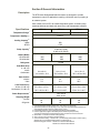
RTE Series
Refrigerated
Bath/Circulators
Digital Controller
Thermo NESLAB Manual P/N U00479
Rev. 12/12/00
Instruction and Operation Manual
idealvac.com
(505)872-0037
idealvac.com
Table of Contents
PREFACE
Compliance .............................................................................................
Unpacking ...............................................................................................
Warranty .................................................................................................
NES-care ................................................................................................
After-sale Support ...................................................................................
2
2
2
2
2
SECTION I
Safety
Warnings ................................................................................................ 3
SECTION II
General Information
Description .............................................................................................. 4
Specifications ......................................................................................... 4
SECTION III
Installation
Site .........................................................................................................
Electrical Requirements ..........................................................................
Plumbing Requirements .........................................................................
Fluids ......................................................................................................
Filling Requirements ...............................................................................
Water Quality Standards and Recommendations ...................................
5
5
6
8
8
9
SECTION IV
Operation
Start Up................................................................................................... 10
Controller Keypad & Display ................................................................... 10
Changing a Value ................................................................................... 11
Controller Displays .................................................................................. 11
Operator's Loop ...................................................................................... 12
Setup Loop ............................................................................................. 13
High Temperature/Low Liquid Level Safety ............................................ 15
9-Pin Accessory Connectors ................................................................... 16
Analog Interface (Optional) ..................................................................... 17
Autorefill (Optional) ................................................................................. 18
Flow Control Valve (Optional) ................................................................. 19
Sealable Bath Lid (Optional) ................................................................... 19
SECTION V
Maintenance
Service Contracts ................................................................................... 20
Reservoir Cleaning ................................................................................. 20
Algae ....................................................................................................... 20
Condenser .............................................................................................. 21
Error Messages ....................................................................................... 21
Additional Loops ..................................................................................... 22
Calibration Loop ...................................................................................... 23
Calibration Procedure ............................................................................. 23
SECTION VI
Troubleshooting
Checklist ................................................................................................. 25
Service Assistance and Technical Support............................................. 26
APPENDIX A
THERMO NESLAB SERIAL COMMUNICATION PROTOCOL
APPENDIX B
PROGRAMMING SOFTWARE/RS232 COMMUNICATION
WARRANTY
-1-
Preface
Compliance
Products tested and found to be in compliance with the requirements defined in the EMC
standards defined by 89/336/EEC as well as Low Voltage Directive (LVD) 73/23/EEC can be
identified by the CE label on the rear of the unit. The testing has demonstrated compliance
with the following directives:
LVD, 73/23/EEC
Complies with UL 3101-1:93
EMC, 89/336/EEC
EN 55011, Class A Verification
EN 50082-1:1992
IEC 1000-4-2:1995
IEC 1000-4-3:1994
IEC 1000-4-4:1995
For any additional information refer to the Letter of Compliance that shipped with the unit
(Declaration of Conformity).
Unpacking
Retain all cartons and packing material until the unit is operated and found to be in good
condition. If the unit shows external or internal damage, or does not operate properly, contact
the transportation company and file a damage claim. Under ICC regulations, this is your
responsibility.
Warranty
Units have a warranty against defective parts and workmanship for one full year from date of
shipment. See back page for more details.
NES-care Extended
Warranty Contract
• Extend parts and labor coverage for an additional year.
• Worry-free operation.
• Control service costs.
• Eliminate the need to generate repair orders.
• No unexpected repair costs.
Other contract options are available. Please contact Thermo NESLAB for
more information.
After-sale Support
Thermo NESLAB is committed to customer service both during and after the sale. If you
have questions concerning the operation of your unit or the information in this manual,
contact our Sales Department. If your unit fails to operate properly or if you have questions
concerning spare parts or Service Contracts, contact our Service Department.
Before calling, please refer to the serial number label on the rear of the unit and page 22 to
obtain the following information:
- BOM number _________________________
- Serial number _________________________
- Software version (see page 22) ___________
-2-
Section I Safety
Warnings
Make sure you read and understand all instructions and safety precautions
listed in this manual before installing or operating your unit. If you have any
questions concerning the operation of your unit or the information in this
manual, contact our Sales Department.
Performance of installation, operation, or maintenance procedures
other than those described in this manual may result in a hazardous
situation and may void the manufacturer's warranty.
Transport the unit with care. Sudden jolts or drops can damage the
refrigeration lines. The units weigh approximately: RTE-111, 86 pounds
(390 kilograms); RTE-211, 99 pounds (45 kilograms); RTE-221, 106
pounds (48 kilograms). Units should be transported with equipment
designed to lift these weights.
Observe all warning labels.
Never remove warning labels.
Never operate damaged or leaking equipment.
Never operate the unit without bath fluid in the bath.
Never use pure ethylene glycol as a bath fluid. Above 80°C the user is
responsible for the fluid used.
For 220 - 240 volt units supplied without a line cord, use a harmonized
(HAR) grounded 3-conductor cord, type H 0 5 V V - F , with conductors
listed below. A suitable cord end is required for connecting to the
equipment (see unit socket) and must terminate with an IEC approved
plug for proper connection to power supply.
RTE-111 and RTE-211
RTE-221
Nominal 1.0 mm2 cross section rated 10 Amps
Unit Socket: IEC - 320 C13
Nominal 1.5 mm2 cross section rated 16 Amps
Unit Socket: IEC - 320 C19
Always turn off the unit and disconnect the line cord from the power
source before performing any service or maintenance procedures, or
before moving the unit.
Always empty the bath before moving the unit.
Never operate equipment with damaged line cords.
Refer service and rep
repairs to a qualified technician.
In addition to the safety warnings listed above, warnings are posted
throughout the manual. These warnings are designated by an exclamation
mark inside an equilateral triangle with text highlighted in bold print. Read
and follow these important instructions. Failure to observe these instructions
can result in permanent damage to the unit, significant property damage,
personal injury or death.
-3-
Section II General Information
Description
The RTE-Series Refrigerated Bath/Circulators are designed to provide
temperature control for applications requiring a fluid work area or pumping to
an external system.
Units consist of a non-CFC air-cooled refrigeration system, circulation pump,
seamless stainless steel bath, work area cover, and a temperature controller.
Specifications
RTE-111
Temperature Range1
RTE-211
-25°C to +150°C
Temperature Stability2,3,4
500
1705
15 lpm at 0' (0 M)
0 lpm at 16' (4.9 M)
Pump Capacity2
800
1000
800
1000
Refrigerant
Bath Work Area
(L x W x D)
Inches
Centimeters
Bath Volume
Gallons
Liters
Case Dimensions6
Inches (H x W x D)
Centimeters (H x W x D)
1600
1800
R134a
43/4 x 8 x 6
12.1 x 20.3 x 15.3
91/4 x 10 x 6
23.5 x 25.4 x 15.2
91/4 x 10 x 9
23.5 x 25.4 x 22.9
1.9
7.0
3.2
12.1
5.4
20.5
25 x 105/16 x 157/8
63.5 x 26.2 x 40.3
25 x 123/8 x 183/8
63.5 x 31.4 x 46.7
277/8 x 123/8 x 183/8
70.8 x 31.4 x 46.7
Power Requirements7
Shipping Weight
Pounds
Kilograms
-23°C to +150°C
±0.01°C
Cooling Capacity2,5
Watts
BTU/H
Heater (Watts)
60 Hz Models
50 Hz Models
RTE-221
115 V, 60 Hz
220V, 50 Hz
86
39
99
45
106
48
1. Low-end temperature for 50Hz units is -18°C, -23°C and -21°C respectively.
2. Specifications listed for units operating to +5°C using water. Other specifications determined
using fluid with specific heat of 0.6, ambient +20°C (+70°F).
3. For operation below 0°C, covering the bath work area may improve stability.
4. For some applications, agitation and stability above ambient may be improved by
connecting a small length of hose between the pump connections on the rear of the unit.
5. 50 Hz RTE-111 units have a 375 watt cooling capacity.
6. Add 1½ inches (3.8 cm) to depth for plumbing fittings.
7. Control transformer fusing - 115VAC units = (T=Time Delay) 500mA 250V 5 x 20mm (Qty 1),
220VAC units =[T=Time Delay] 250mA 250V to 5 x 20mm (Qty 2).
Bussman fusing part numbers: 500mA fuse = Bussman S504-500mA
250mA fuse = Bussman S504-250mA
-4-
Section III Installation
Site
The indentations on the unit's sides are designed to function as handles. Lift
the unit by the handles and locate it on a sturdy work area. Ambient temperatures should be inside the range of +50°F to +104°F (+10°C to +40°C).
Never place the unit in a location where excessive heat, moisture, or
corrosive materials are present.
The unit has an air-cooled refrigeration system. Air is drawn through the
front panel and discharged through the rear panel. The unit must be
positioned so the air intake and discharge are not impeded. A minimum
clearance of 12 inches (30 centimeters) at the front and rear of the unit is
necessary for adequate ventilation. Inadequate ventilation will reduce
cooling capacity and, in extreme cases, can cause compressor failure.
Excessively dusty areas should be avoided and a periodic cleaning schedule
should be instituted (see Section VI, Cleaning).
The unit will retain its full rated capacity in ambient temperatures up to
approximately +75°F (+24°C). Above +75°F, reduce the cooling capacity 1%
for every 1°F above +75°F, to a maximum ambient temperature of +104°F.
In terms of Celsius, reduce the cooling capacity 1% for every 0.5°C above
+24°C, to a maximum ambient temperature of +40°C.
Electrical
Requirements
Line voltage may be easily accessible inside the pump/control box.
Always unplug the unit prior to removing pump/control box cover.
Refer to the serial number label on the rear of the unit to identify the specific
electrical requirements of your unit.
Ensure the voltage of the power source meets the specified voltage, ±10%.
The unit construction provides extra protection against the risk of electric
shock by grounding appropriate metal parts. The extra protection may not
function unless the power cord is connected to a properly grounded outlet. It
is the user's responsibility to assure a proper ground connection is provided.
For 220 - 240 volt units supplied without a line cord, use a harmonized
(HAR) grounded 3-conductor cord, type H 0 5 V V - F , with conductors
listed below. A suitable cord end is required for connecting to the
equipment (see unit socket) and must terminate with an IEC approved
plug for proper connection to power supply.
RTE-221
Nominal 1.5 mm2 cross section rated 16 Amps
RTE-111 and RTE-211
Nominal 1.0 mm2 cross section rated 10 Amps
Unit Socket: IEC - 320 C19
Unit Socket: IEC - 320 C13
-5-
Plumbing
Requirements
Ensure the unit is off before connecting tubing to the unit.
To prevent damage to the plumbing lines, always support the ¾"
fittings while installing/removing the pumping caps and lines.
Hose Connections
The pump connections are located at the rear of the pump box and are
labelled PUMP INLET and PUMP OUTLET. These connections are bent
upward so the recirculating fluid will drain back into the reservoir when the
hoses are disconnected. Both connections are capped with stainless steel
serrated plugs.
The pump lines have ¼" MPT for mating with standard plumbing fittings. For
your convenience stainless steel adapters, ¼" FPT to 3/8" O.D. serrated
fitting, are provided. (To assure proper fit, they should be installed using 1½
turns of Teflon® tape around the threads.)
Flexible tubing, if used, should be of heavy wall or reinforced construction.
Make sure all tubing connections are securely clamped. Avoid running
tubing near radiators, hot water pipes, etc. If substantial lengths of tubing
are necessary, insulation may be required to prevent loss of cooling capacity. Tubing and insulation are available from Thermo NESLAB. Contact our
Sales Department for more information (see Preface, After-sale Support).
It is important to keep the distance between the unit and the external system
as short as possible, and to use the largest diameter tubing practical. Tubing
should be straight and without bends. If diameter reductions must be made,
make them at the inlet and outlet of the external system, not at the unit.
If substantial lengths of cooling lines are required, they should be pre-filled
with bath fluid before connecting them to the unit. This will ensure that an
adequate amount of fluid will be in the bath once it is in operation.
Pumping
The pump is designed to deliver a flow of 15 liters per minute (4 gallons per
minute) at 0 feet head. To prevent external circulation, the PUMP INLET
and PUMP OUTLET lines on the rear of the unit are capped. The caps must
be removed when external circulation is required.
To properly secure external hose connections to the unit, wrap Teflon® tape
around the pipe line threads before installation. Once the hose connections
are made, the hoses must be properly plumbed to an external system. It is
important the bath is not in operation until all plumbing is complete.
NOTE: To increase agitation in the bath when not circulating externally,
connect a short loop of hose between the inlet and outlet lines.
If the bath is not used for external circulation or increased agitation, make
sure the stainless steel caps are in place prior to operating the bath.
-6-
Circulating to an open container
Levelling
Device
Outlet
Inlet
Bath (Rear View)
Open Container
A stainless steel leveling device is available to aid circulation to an open
vessel. Contact our Sales Department for more information (see Preface).
Support the leveling device over the open container with a ringstand.
Stagger the tubes in the leveling device so one tube is submerged in the
vessel fluid, and the other tube is level with the fluid surface. Connect the
deeper tube to the PUMP OUTLET and the shorter tube to the PUMP
INLET.
Adjust the flow rate using the accessory flow control valve connected to the
PUMP OUTLET, or by partially restricting the outlet tubing. When properly
adjusted, the pump inlet will draw an occasional air bubble to prevent over
flow, and the pump outlet will force fluid through the submerged tube to
prevent aeration of the vessel.
To avoid siphoning the bath work area when the unit is shut off, lift the
leveling device out of the vessel and above the level of the unit.
Circulating through two closed-loops
Pump Box
System #1
Bath
Work Area
System #2
Bath (Top View)
The pump can be used to circulate through two closed-loop systems.
Connect the shortest practical length of flexible tubing from the PUMP
OUTLET to the inlet of external system #1. Connect the outlet of system #1
directly into the bath work area. Connect tubing from the bath work area to
the inlet of system #2. Connect the outlet of system #2 to the PUMP INLET.
-7-
Drain
Ensure the temperature of the bath fluid is safe before draining the unit.
The unit is equipped with a drain located at the back of the unit at the base
of the bath. The drain has ¼" MPT and is capped with a stainless steel plug.
To drain the reservoir simply remove the cap.
To assure proper fit when replacing the cap, be sure to line the threads with
1½ turns of Teflon® tape.
Fluids
Never use flammable or corrosive fluids with this unit.
The selected fluid must have a viscosity of 50 centistokes or less at the
lowest operating temperature.
Filtered tap water is the recommended fluid for operation from +8°C to
+80°C. See Water Quality Standards and Recommendation on the next
page.
For operation from -30°C to +8°C, a 50/50 mixture, by volume, of tap water
and laboratory grade ethylene glycol is suggested.
Never use pure ethylene glycol as a bath fluid. Above 80°C and below
-30°C, the user is responsible for the fluid used.
Filling
Requirements
The bath work area has a high and low level marker to guide filling. The
markers are 1 inch horizontal slits located in the center of the stainless steel
baffle separating the work area and the pump assembly. The correct fluid
level falls between these two markers. The heating and cooling coils will be
exposed and may become damaged if the correct fluid level is not provided.
When pumping to an external system, keep extra fluid on hand to maintain
the proper level in both the circulating lines and the external system.
Never run the unit when the work area is empty. Avoid overfilling.
Overfilling the bath may damage the insulation and affects stability as
well as low-end performance.
-8-
Water Quality Standards
and Recommendations
Permissible (PPM)
Desirable (PPM)
Microbiologicals
(algae, bacteria, fungi)
0
Inorganic Chemicals
Calcium
<40
Chloride
250
Copper
1.3
Iron
0.3
Lead
0.015
Magnesium
<12
Manganese
0.05
Nitrates\Nitrites
10 as N
Potassium
<20
Silicate
25
Sodium
<20
Sulfate
250
Hardness
17
Total Dissolved Solids
50
Other Parameters
pH
6.5-8.5
Resistivity
0.01*
* Megohm-Cm (Compensated to 25°C)
0
0.6
<25
1.0
<0.1
0
0.1
<0.03
0
0.3
<1.0
0.3
<50
<0.05
10
7-8
0.05-0.1*
Unfavorably high total ionized solids (TIS) can accelerate the rate of galvanic corrosion. These contaminants can function as electrolytes which
increase the potential for galvanic cell corrosion and lead to localized
corrosion such as pitting which can be observed at the studs and on the
outside surface of cooling coils. Eventually, the pitting will become so
extensive that the coil will leak refrigerant into the water reservoir.
For example, raw water in the U.S. averages 171 ppm (of NaCl). The
recommended level for use in a water system is between 0.5 to 5.0 ppm (of
NaCl).
Recommendation: Initially fill the tank with distilled/deionized water. Do not
use untreated tap water, as the total ionized solids level may be too high.
Maintain this water quality at a resistivity of between 1 to 10 megohm-cm
(compensated to 25°C) by using a purification system. Although the initial fill
may be as high as 10 megohm-cm (compensated to 25°C), the desired level
for long time usage is 1 to 3 megohm-cm (compensated to 25°C).
The above two recommendations will reduce the electrolytic potential of the
water and prevent or reduce the galvanic corrosion observed.
Not Recommended, Increasingly Corrosive
Resistivity (megohm-cm @ 25°C)
15.00
10.00
Operations with Stainless Steel Systems
3.00
1.00
Operations with
Mixed Metals
Copper/Brass/
Stainless Steel
CONSULT MATERIALS ENGINEER
0.10
0.05
10
20
30
40
50
60
Water Quality Considerations
-9-
70
80
°C
Section IV Operation
Start Up
Before starting the unit, check all electrical and plumbing connections and
make sure the work area has been properly filled with bath fluid.
To start the bath, place the I/O circuit breaker on the side of the control box
to the I (power on) position. The pump will start and the controller will display
the temperature of the fluid in the reservoir.
The digital controller controls temperature using a PID (Proportional-IntegralDerivative) algorithm. It is designed with self-diagnostic features and easy to
use operator interface.
Controller Keypad
& Display
The controller's HEAT and COOL indicators show the status of the refrigeration system and heater. The HEAT indicator is lit when the heater is on. The
HEAT indicator flashes when the heater is pulsating. The COOL indicator is
lit when the refrigeration system is removing heat from the cooling fluid. A
balance between COOL and HEAT controls the temperature.
NOTE: Below 50°C the refrigeration system is on unless the setpoint is more
than 2°C above the bath temperature. This allows for rapid heat up. Above
50°C the refrigeration system is off unless the setpoint is more than 2°C
below the bath temperature. This allows for rapid cool down.
The REMOTE indicator illuminates whenever the unit is configured to accept
a remote setpoint. The controller's SENSOR indicator illuminates whenever
the optional external sensor is selected. See Controller Displays on the next
page for information on the °C display.
NEXT ENTER
Use this key to scroll forward through the menus and also to accept and
save changes.
- 10 -
YES,
This dual purpose key is used to answer Yes to Y/N questions or to increment numerical values upward for setting numeric values.
NO,
This dual purpose key is used to answer No to Y/N questions or to decrement numerical values downward for setting numeric values.
Changing a Value
The YES key increments the value. The NO key decrements the value.
The display will flash as soon as either key is depressed, and will continue to
flash until the NEXT ENTER key is pressed twice to accept the new value.
The new value will not be used by the controller until the NEXT ENTER key
is depressed twice and the display stops flashing.
NOTE: If the ENTER key is not depressed twice within 10 seconds, the
controller will time out and the new value will not be accepted. The controller
will revert to the previous setpoint value.
The controller will not allow you to enter a value above the maximum or
below the minimum (normally +150°C and -25°C).
Controller Displays
An alphanumeric display presents numeric readings of various operating
conditions within the bath. Display function is selected by pressing the
appropriate keys to move through a menu of available information.
When the controller is first powered up it performs a quick self-test then
enters the Operator's Loop. The Operator's Loop displays the bath temperature and is used to change the setpoint, see page 12. The Setup Loop can be
accessed from the Operator's Loop by pressing and holding the key combinations shown on Figure 1 on the next page. The Setup Loop is used to adjust
the controller's PID parameters, select either the internal or optional external
sensor, and set the high/low temperature limits. It is also used to select RS232
parameters and display the unit's identification number. See pages 13-14.
- 11 -
Operator's Loop
When the controller is first powered up it enters the Operator's Loop, displaying reservoir fluid temperature. Press the NEXT ENTER key to view the
setpoint.
SP displays the controller setpoint. The display will flash between SP and
the actual setpoint number. Use the YES/NO keys to change the setpoint
value. Once the desired setpoint is displayed, press the NEXT ENTER key
twice.
NOTE: If the bath is controlled via RS232 communications, the setpoint can
not be changed from the keypad.
XXX.X = Reservoir Fluid Temperature
SP = Setpoint
Figure 1 Operator's Loop
- 12 -
Setup Loop
The Setup Loop is used to adjust the controller's PID parameters; select either
the internal (1) or optional external (2) sensor; set the high/low temperature
limits; adjust RS232 parameters; and display/alter the unit's ID number.
Enter the Setup Loop from the Operator's Loop by pressing and holding the
NO key, then press the NEXT ENTER key. Use the YES/NO keys to adjust
the values. Press the NEXT ENTER key twice to accept the new value.
Press the NEXT ENTER key only once if the value did not change.
While in the Setup Loop, if a key is not pressed during a one-minute time
span, the controller will automatically return to the Operator's Loop.
NOTE: If the unit exceeds either temperature limit, the appropriate error
message will flash, see page 21. The unit will not shut down (unless the
temperature also exceeds the high temperature safety setting, see page
15).You will also receive an error code if the optional external sensor is
selected but it is not installed.
tUnE = Tune
HEAt = Heat PID Parameters
Pro = Proportional Band (factory value 1.3%)
Int = Integral (factory value 0.75 repeats per minute)
dEr = Derivative (factory value 0.05 minutes)
rtd = Sensor
1 = Internal
2 = External
SP = Setpoint source (optional display see page 17)
Hit = High Temperature Limit
Optional. Selecting Analog Input
(AnA) as the mode of temperature
control overrides both manual
input from the keypad, and any
serial communication input.
Figure 2 Setup Loop (1 of 2)
- 13 -
Hit = High Temperature Limit
Lot = Low Temperature Limit
r232 = RS232 Protocol
bAUd = BAUD rate (default 9600)
dAtA = Data Bits (default 8)
StoP = Stop Bit (default 1)
PAr = Parity (default NONE)
U id = Unit Identification Number (used for
serial communication)
Stor = Store
Figure 2 Setup Loop (2 of 2)
NOTE: To save all changes, when the display reads Stor press YES. Should
you desire to return to the temperature display and abort all changes, when
the display reads Stor press NO.
- 14 -
High Temperature/
Low Liquid
Level Safety
To protect your application, the adjustable High Temperature/Low Liquid
Level Safety (HIGH TEMP/LOW LEVEL) ensures the heater will not exceed
temperatures that can cause serious damage to your unit. A single temperature sensor, located on the heater coils in the bath, monitors both conditions.
A High Temperature/Low Liquid Level fault occurs when the temperature of
the sensor exceeds the set temperature limit. The safety switch has a
temperature range of 7°C to 180°C.
In the event of a fault, the red LED near the adjustment dial will light, the
display will go blank, and the unit will shut down. The cause of the fault must
be identified and corrected before the unit can be restarted.
The safety is not preset and must be adjusted during initial installation.
To set the safety, locate the HIGH TEMP/LOW LEVEL SAFETY adjustment
dial on the right side of the pump box. Turn the dial fully clockwise and turn
the I/O switch off then back on.
Start the unit. Adjust the setpoint for a few degrees higher than the highest
desired fluid temperature and allow the bath to stabilize at the temperature
setpoint. Turn the HIGH TEMP/LOW LEVEL SAFETY dial counterclockwise
until you hear a click and the unit shuts down. The red LED near the adjustment dial will light to indicate a fault has occurred.
Cool the bath and then, without moving the adjustment dial, turn the I/O
switch off then back on.
NOTE: Thermo NESLAB recommends rechecking operation if the unit is
moved.
High Temperature/Low Liquid Level Safety
- 15 -
9-Pin Accessory
Connector
The unit is equipped with two 9-pin D-connectors located on the rear of the
control box. The female COMM is used for RS232 communication (see
Appendix A); the male is used with an optional external sensor.
SENSOR
COMM
COMM Pin Connections
Pin #
1
2
3
4
5
6
7
8
9
Hardware
Function
No connection.
TX = Transmitted data from controller
RX = Received data to controller
No connection
GND = Signal ground
No connection.
No connection
No connection
No connection
Internal Connector
AMP Part# 745491-2
Mating Connector
AMP Part# 745492-2
Remote Sensor Connections
Function
3-wire RTD connection A
2
3
4
5
6
7
No connection
No connection
3-wire RTD connection A
No connection
No connection.
3-wire RTD connection B
8
9
No connection
No connection
Hardware
Internal Connector
AMP Part# 745492-2
- 16 -
Example
RTD
Pin #
1
Mating Connector
AMP Part# 745491-2
Analog Interface
(Optional)
An optional 15-pin D subminiature female receptacle for analog interface is
located on the rear of the control/pump box.
Pin #
Function
ACCESSORY
1
Chassis ground.
2
No connection.
3-5
No connection.
6
Analog Ground. The analog ground is physically separated from the power ground throughout the
unit. To prevent offsets that result from ground currents, the analog and power grounds are only
connected at the unit's power supply. Analog ground should only be used as a reference pin.
7
Temperature Out. The fluid temperature, as measured by the sensor slected in theSetup Loop (see page
13) , can be read at this pin. The temperature scale is 10mV/°C, referenced to analog ground,
pin 6 (example: +150mV = +15.0°C).
8
No connection.
9
Power Ground (5V RTN).
10 - 13
No connection.
14
+5V. Power supply of +5VDC (15mA maximum).
15
Setpoint In. The temperature setpoint can be controlled by applying a known voltage to this pin. The
temperature scale is 10mV/°C, referenced to analog ground, pin 6 (example: +230mV = +23.0°C).
Note: The setpoint is updated only when the voltage represents a temperature within the setpoint limits.
The analog setpoint signal (Setpoint In) is enabled using the unit's software. Using the
Setup Loop discussed on page 13, keep depressing the NEXT ENTER key until SP is
displayed. Use the YES or NO key to display the desired mode, AnA for analog or LoC
for local, then press NEXT ENTER to continue with the loop. NOTE: The last value
entered is maintained when SP is changed from AnA to LOC or LOC to AnA until a valid
voltage is applied.
Store the change.
NOTE: Selecting Analog Input (AnA) as the mode of temperature control overrides both
manual input from the keypad, and any serial communication input.
The Analog In and Analog Out
discussed in the Calibration Loop
on pages 23 and 24 is applicable
to this unit. Analog In calibration
is done by applying a 2Vdc
signal for AiH, and a 0Vdc signal
for AiL. Reference the appropriate pins on the ACCESSORY
connector.
Analog Out calibration is done by
measuring the appropriate pins
on the ACCESSORY connector.
Adjust the AoH to 1.000Vdc
using the YES and NO keys then
press ENTER twice. Adjust the
AoL to 0.000Vdc using the YES
and NO keys then press ENTER
twice.
- 17 -
Autorefill (Optional)
The autorefill device is designed to maintain the correct level of fluid in the
reservoir. The device consists of a float switch and a solenoid valve. If the
fluid level falls, the float switch opens the solenoid valve allowing makeup
fluid to fill the reservoir. Once the fluid reaches the proper level, the float
switch rises and the solenoid valve closes.
The plumbing connection for the autorefill device, labeled WATER INLET, is
located on the rear of the autorefill assembly. The connection is 3/8" OD
stainless steel. To prevent damage to your hosing and to prevent the hose
from slipping of the connection, install the supplied hose barb into your
tubing. Tubing is also available from Thermo NESLAB. Contact our Sales
Department.
Remove the nut on the WATER INLET connection and install the tubing
from your makeup fluid source. Reinstall the nut and tubing on the connection. Install the device on the unit. To secure the device to the unit, tighten
the screw located between the float switch and the makeup fluid outlet line.
If desired, place the supplied cover on the unit.
The autorefill device requires its own source of electrical power. A connector
for the supplied line cord is also located on the rear of the autorefill device.
The connector is labelled POWER.
Float Switch
POWER
Makeup Fluid
Outlet Line
WATER INLET
- 18 -
Flow Control
Valve (Optional)
An optional flow control valve is available to control external circulation. The
valve assembly consists of the nine pieces shown below. Once assembled
and installed on the unit, clamp a hose to the end of the assembly. Turn the
unit on and check for leaks with the valve opened as well as closed.
Direction of Flow
Finger Tight
E
OP N
C
Finger Tight +1¼ Turn
LO S E
External Hose Connections
Bath Connections
Spare Part
Sealable Bath Lid
(Optional)
Depending on your application
requirements and/or working environment, a bath lid is available to
make RTE-111 reservoirs sealable
(not pressurized).
Nitrogen Purge
Latch
The top of the pump grate in the
unit's reservoir has four holes cut
into the sheet metal. Align the
protrusions on the lid with these
holes as shown. A locking adjustable
grip latch tightens the lid to the tank top allowing
an EDPM gasket to create a seal.
Holes
The lid also has a nitrogen purge port. The purge port is a ¼" male Swageloc
connector with an o-ring seal.
- 19 -
Section V Maintenance
To avoid electrical shock, disconnect the mains cord prior to removing any access panels or covers.
Service Contracts
Thermo NESLAB offers on-site Service Contracts designed to provide
extended life and minimal down-time for your unit. For more information,
contact our Service Department (see Preface, After-sale Support).
Reservoir Cleaning
Routine cleaning can be achieved by simply sponging down the seamless
stainless steel tank with tap water. (Dish washing detergent may be used
but the tank must be thoroughly rinsed.)
To gain access to the entire reservoir the pump box and reservoir cover
should be removed.
Refrigeration Cable
Cable Strap
Remove the line cord from the rear of the unit and then remove the four
screws (two on each side) securing the reservoir's cover.
To get slack on the refrigeration cable, remove the cable strap. The cable
itself does not need to be disconnected.
Turn the cover assembly over and carefully place it on a supporting platform.
Algae
To restrict the growth of algae in the bath, we recommend the bath cover be
kept in place and that all circulation lines be opaque. This will eliminate the
entrance of light required for the growth of most common algae.
Thermo NESLAB recommends the use of Chloramine-T, 1 gram per 3½
liters.
- 20 -
Condenser
For proper operation, the unit needs to pull substantial amounts of air
through a condenser. A build up of dust or debris on the fins of the
condenser will lead to a loss of cooling capacity.
Periodic vacuuming of the condenser is necessary. To access the condenser
the front grille must be removed.
The unit must be turned off before the front panel is removed.
RTE-111 units have a one-piece grille assembly. Pull forward to remove.
RTE-211 and RTE-221 units have a two piece grille assembly. First remove
the left (blue-colored) section by simply pulling it forward. Pull forward on the
remaining (white-colored) section to remove it.
The frequency of cleaning depends on the operating environment. After
initial installation, we recommend a monthly visual inspection of the condenser. After several months, the frequency of cleaning will be established.
Error Messages
Error
Action
Er00:
Er01:
Er02:
Er04-13:
Er14:
Er15:
Er16:
LoT:
HiT:
Er23:
Er24:
Er25:
Er26:
HTC:
PrES:
ROM Checksum
RAM Test Failed
Keypad Test Failed
Interrupt Error
Synchronous Error
Asychronous Error
Bad Calibration
Low Temp Limit
High Temp Limit
RTD2 Shorted
RTD2 Open/Not Installed
RTD1 Shorted
RTD1 Open
High Temperature Cutout
Pressure Cutout
NOTE: HTC and PrES are optional displays available only on specially
modified units. Errors 00 through 15 will lockup the controller keypad. Errors
00 through 03 may be cleared by depressing the NEXT ENTER key.
- 21 -
Additional Loops
1, 2, ... = A, B, ...
Figure 3 Additional Loops
- 22 -
Calibration Loop
The Calibration Loop is used to calibrate the RTD high and low temperature.
The controller's internal temperature sensor is factory calibrated. We
recommend calibrating any external sensor.
Enter the Calibration Loop from the Operator's Loop by pressing and holding
the NO key while pressing the YES key three times.
Calibration
Procedure
Install a calibrated reference thermometer in the bath. (For external mode,
also install the sensor in the bath.) Place the cover on the unit.
The procedure uses the Operator's, Setup and Calibration Loops. In the
Setup Loop place the unit in either the internal or external RTD mode of
operation (RTD1 = Internal , RTD2 = External). Return to the Operator's
Loop and adjust the setpoint to an appropriate high-end temperature.
NOTE: When calibrating the external sensor ensure the controller's
SENSOR indicator is illuminated.
Once the bath reaches the setpoint and stabilizes, go to the Calibration
Loop and, as illustrated on the next page, enter the actual reference thermometer reading at either the r1H or r2H prompt.
Store the change and return to the Operator's Loop. Adjust the setpoint to
an appropriate low-end temperature. Once the bath reaches the setpoint
and stabilizes, return to the Calibration Loop and enter the reference thermometer reading at either the r1L or r2L prompt. Store the change.
Do not pick points that are outside the safe operating limits of the
fluid in your application. For example with a water bath, 90°C and 5°C
would be typical calibration points.
- 23 -
rtdn n= 1 = Internal sensor, n = 2 = external sensor
rnH = High temperature
rnL = Low temperature
Ain = Only applicable to units with analog interface
Aout = Only applicable to units with analog interface
Stor = Store
Figure 4 Calibration Loop
NOTE: To save all changes, when the display reads Stor press YES. Should
you desire to return to the temperature display and abort all changes, when
the display reads Stor press NO.
- 24 -
Section VI Troubleshooting
Checklist
Unit will not start
Make sure the voltage of the power source meets the specified voltage,
±10%. Refer to the serial number label on the rear of the unit to identify the
specific electrical requirements of your unit.
Check the High Temperature/Low Liquid Level Safety. If the red LED on the
side of the controller is on, make sure the fluid level in the bath is between
the marks in the baffle and the HIGH TEMP/LOW LEVEL SAFETY setting is
greater than the fluid temperature. Turn the I/O switch off then back on, and
attempt to restart.
Loss of cooling capacity
Be sure the cooling capacity of the unit has not been exceeded if circulating
to an external system.
When the unit is shut off, wait approximately five minutes before restarting.
This allows time for the refrigeration pressures to equalize. If the pressures
are not allowed to equalize, the compressor will short-cycle (clicking sound)
and no cooling will occur.
Proper ventilation is required for heat removal. Make sure ventilation
through the front and rear panels is not impeded and the panels are free of
dust and debris.
Ice build up on the cooling coils can act as insulation and lower the cooling
capacity. Raise the temperature of the bath to de-ice the cooling coil and
increase the concentration of non-freezing fluid.
No external circulation
Check for obstructions, kinks, or leaks in the circulation tubing.
Circulation will cease when the pump head has been exceeded.
No/poor temperature control
Check RS232/remote operation on or off.
Selecting the optional Analog Input (AnA) as the mode of temperature
control overrides both manual input from the keypad, and any serial
communication input.
Check external sensor connection. Perform calibration.
Continued on next page.
- 25 -
No serial communications
All units are tested for serial communications before they leave the factory.
Ensure the REMOTE indicator on the controller is illuminated.
Check all communications commands, they must be exact. See Appendix A.
Check communications settings. The protocol uses an RS-232 serial interface with the parameters: 9600 baud, 8 data bits, 1 stop bit and no parity.
Check all wiring for proper connections or possible shorts.
Software to verify serial communication is available from Thermo NESLAB.
Service Assistance and
Technical Support
If, after following these troubleshooting steps, your unit fails to operate
properly, contact our Customer Service Department for assistance (see
Preface, After-sale Support). In addition to arranging warranty service, our
Service Department can provide you with a wiring diagram and a complete
list of spare parts for your unit. Before calling, please obtain the following:
Part number
Serial number
Software Version
- 26 -
Appendix A
Serial Communications Protocol
NOTE: This appendix assumes you have a basic understanding of communications protocols.
All data is sent and received in binary form, do not use ASCII. In the following pages the binary data is represented in hexadecimal (hex) format.
The Neslab Serial Communications Protocol, NC, is based on a masterslave model. The master is a host computer, while the slave is the bath's
controller. Only the master can initiate a communications transaction (halfduplex). The slave ends the transaction by responding to the master’s query.
The protocol uses an RS-232 serial interface with the default parameters:
9600 baud, 1 start bit, 8 data bits, 1 stop bit and no parity.
NOTE: Before the unit will communicate, RS232 must be turned on in the
controller's Setup Loop.
The unit can be controlled through your computer’s serial port by using the
unit's standard 9-pin RS-232 connection. Data read of the serial port connects to the data transmit (pin 2) of the bath. Data transmit of the serial port
connects to data read (pin 3) of the bath.
Communication cables are available from Thermo NESLAB. Contact our
sales department for additional information.
All commands must be entered in the exact format shown in the tables on
the following pages. The tables on on the last page of this Appendix show all
commands available, their format and responses. Controller responses are
either the requested data or an error message. The controller response must
be received before the host sends the next command.
The host sends a command embedded in a single communications packet,
then waits for the controller’s response. If the command is not understood or
the checksums do not agree, the controller responds with an error command.
Otherwise, the controller responds with the requested data. If the controller
fails to respond within 1 second, the host should resend the command.
- 27 -
NC Serial Communications Protocol
NOTE: All byte values are shown in hex, hex represents the binary values that must be sent to the bath. Do
not use ASCII.
The framing of the communications packet in both directions is:
Checksum region
Lead char
CA
Addr-MSB
00
Addr-LSB Command
01
n d-bytes
d-byte 1
...
d-byte n
Checksum
Lead char
CA (hex).
Addr-msb
Addr-lsb
Device address is 1
Most significant byte of device address is 00 hex.
Least significant byte of device address is 01 hex.
Command
Command byte (see Table 1).
n d-bytes
d-byte 1
...
d-byte n
Checksum
Number of data bytes to follow (00 to 03 hex).
1st data byte (the qualifier byte is considered a data byte).
...
nth data byte.
Bitwise inversion of the 1 byte sum of bytes beginning with the most significant address byte and ending with the byte preceding the checksum. (To
perform a bitwise inversion, "exclusive OR" the one byte sum with FF hex.)
The master requests information by sending one of the Read Functions as shown in Table 1 on page 30.
Since no data is sent to the bath during a read request, the master uses 00 for the number of data bytes
following the command byte.
The bath will respond to a Read Function by echoing the lead character, address, and command byte,
followed by the requested data and checksum. When the bath sends data, a qualifier byte is sent first,
followed by a two byte signed integer (16 bit, MSB sent first). The qualifier byte indicates the precision and
units of measure for the requested data as detailed in Table 2, see page 30.
As an example, the master requests to read internal temperature by sending:
The checksum is the bitwise
inversion of 21 (00+01+20+00)
command byte
CA 00 01 20 00 DE
byte values are in hex
0 bytes of data
If the temperature is -10.5°C, the slave would reply:
The qualifier byte of 11 indicates a precision of 1
decimal point and units of °C. The temperature of
-10.5°C is -105 decimal = FF97 hex.
command byte
CA 00 01 20 03 11 FF 97 34
The checksum is the bitwise inversion of
C8 (00+01+20+03+11+FF+97)
3 bytes to follow
- 28 -
The master sets parameters in the bath by sending one of the Set Functions as shown in Table 1. The
master does not send a qualifier byte in the data field. The master should be preprogrammed to send the
correct precision and units (it could also read the parameter of interest first to decode the correct precision
and units needed).
For example, if the master wants to set the setpoint to 30°C, it would send :
The checksum is the bitwise inversion of 20
(00+01+F0+02+01+2C)
command byte
CA 00 01 F0 02 01 2C DF
2 bytes to follow
The temperature of 30.0°C is 300 decimal = 012C hex.
The slave responds:
The qualifier byte of 11 indicates a precision of 1
decimal point and units of °C. The temperature of
30.0°C is 300 decimal = 012C hex.
command byte
CA 00 01 F0 03 11 01 2C CD
The checksum is the bitwise inversion of
32(00+01+F0+03+11+01+2C)
3 bytes to follow
- 29 -
Table 1 (All bytes are in hex)
FUNCTION
MASTER SENDS
BATH RESPONDS
READ
Read Internal Temperature
Read External Sensor
Read Setpoint (control point)
Read Low Temperature Limit
Read High Temperature Limit
Read Proportional Band (P)
Read Integral (I)
Read Derivative (D)
CA 00 01 20 00 DE
CA 00 01 21 00 DD
CA 00 01 70 00 8E
CA 00 01 40 00 BE
CA 00 01 60 00 9E
CA 00 01 71 00 8D
CA 00 01 72 00 8C
CA 00 01 73 00 8B
CA 00 01 20 03 qb d1 d2 cs
CA 00 01 21 03 qb d1 d2 cs
CA 00 01 70 03 qb d1 d2 cs
CA 00 01 40 03 qb d1 d2 cs
CA 00 01 60 03 qb d1 d2 cs
CA 00 01 71 03 qb d1 d2 cs
CA 00 01 72 03 qb d1 d2 cs
CA 00 01 73 03 qb d1 d2 cs
SET
Set Setpoint (control point)*
Set Low Temperature Limit*
Set High Temperature Limit*
Set Proportional Band
(P=1-99.9)
Set Integral (I = 0-9.99)
Set Derivative (D= 0-5.0)
CA 00 01 F0 02 d1 d2 cs
CA 00 01 C0 02 d1 d2 cs
CA 00 01 E0 02 d1 d2 cs
CA 00 01 F1 02 d1 d2 cs
CA 00 01 F0 03 qb d1 d2 cs
CA 00 01 C0 03 qb d1 d2 cs
CA 00 01 E0 03 qb d1 d2 cs
CA 00 01 F1 03 qb d1 d2 cs
CA 00 01 F2 02 d1 d2 cs
CA 00 01 F3 02 d1 d2 cs
CA 00 01 F2 03 qb d1 d2 cs
CA 00 01 F3 03 qb d1 d2 cs
BATH ERROR RESPONSES
Bad Command
Bad Checksum
N/A
N/A
CA 00 01 0F 02 01 ed cs
CA 00 01 0F 02 03 ed cs
MISCELLANEOUS
Request Acknowledge
CA 00 01 00 00 FE
CA 00 01 00 02 v1 v2 cs
command bytes shown in bold
qb = qualifier byte
d1,d2 = 16 bit signed integer of the value being sent or received
cs = the checksum of the string (see text)
ed = echo back of the command byte as received
v1,v2 = protocol version
* = limited to the range of the bath
Table 2
QUALIFIER BYTE
10 hex
20 hex
11 hex
0.1 precision, no units of measure
0.01 precision, no units of measure
0.1 precision, °C units
Example: The temperature of 45.6 °C would be represented by the qualifier 11 hex, followed by the 2 bytes
01 C8 hex (456 decimal).
Appendix B Programming Software
NEScom Software/
RS232 Communication
The Thermo NESLAB Communications Software is a user-friendly software
that allows you to automate your temperature control process. The software
includes a 3½" disk, comprehensive operator’s manual and a toll-free
number to a trained technical staff.
NEScom Software allows you to write custom temperature programs for our
Digital or Microprocessor based temperature control apparatus. Choose
upper or lower temperature limits and monitor system status with an alarm.
NEScom can also record your results on a user selectable graph. NesCom
must be used with an IBM or 100% compatible computer.
Select from easy to use product icons.
Create graphs and charts.
Easily configure ramping functions that set the setpoint over time.
View pop-up alarm windows that display if an alarm condition occurred.
Select software functions from the easy to use pulldown menus.
View a virtual controller screen which allows remote monitoring
and operation of product control panel.
WARRANTY
Thermo NESLAB Instruments, Inc. warrants for 12 months from date of shipment any Thermo NESLAB unit
according to the following terms.
Any part of the unit manufactured or supplied by Thermo NESLAB and found in the reasonable judgment of
Thermo NESLAB to be defective in material or workmanship will be repaired at an authorized Thermo
NESLAB Repair Depot without charge for parts or labor. The unit, including any defective part must be
returned to an authorized Thermo NESLAB Repair Depot within the warranty period. The expense of returning the unit to the authorized Thermo NESLAB Repair Depot for warranty service will be paid for by the
buyer. Thermo NESLAB’s responsibility in respect to warranty claims is limited to performing the required
repairs or replacements, and no claim of breach of warranty shall be cause for cancellation or recision of the
contract of sales of any unit.With respect to units that qualify for field service repairs, Thermo NESLAB’s
responsibility is limited to the component parts necessary for the repair and the labor that is required on site
to perform the repair. Any travel labor or mileage charges are the financial responsibility of the buyer.
The buyer shall be responsible for any evaluation or warranty service call (including labor charges) if no
defects are found with the Thermo NESLAB product.
This warranty does not cover any unit that has been subject to misuse, neglect, or accident. This warranty
does not apply to any damage to the unit that is the result of improper installation or maintenance, or to any
unit that has been operated or maintained in any way contrary to the operating or maintenance instructions
specified in Thermo NESLAB’s Instruction and Operation Manual. This warranty does not cover any unit that
has been altered or modified so as to change its intended use.
In addition, this warranty does not extend to repairs made by the use of parts, accessories, or fluids which are
either incompatible with the unit or adversely affect its operation, performance, or durability.
Thermo NESLAB reserves the right to change or improve the design of any unit without assuming any
obligation to modify any unit previously manufactured.
THE FOREGOING EXPRESS WARRANTY IS IN LIEU OF ALL OTHER WARRANTIES, EXPRESSED OR
IMPLIED, INCLUDING BUT NOT LIMITED TO WARRANTIES OR MERCHANTABILITY AND FITNESS
FOR A PARTICULAR PURPOSE.
Thermo NESLAB’S OBLIGATION UNDER THIS WARRANTY IS STRICTLY AND EXCLUSIVELY LIMITED
TO THE REPAIR OR REPLACEMENT OF DEFECTIVE COMPONENT PARTS AND Thermo NESLAB
DOES NOT ASSUME OR AUTHORIZE ANYONE TO ASSUME FOR IT ANY OTHER OBLIGATION.
Thermo NESLAB ASSUMES NO RESPONSIBILITY FOR INCIDENTAL, CONSEQUENTIAL, OR OTHER
DAMAGES INCLUDING, BUT NOT LIMITED TO LOSS OR DAMAGE TO PROPERTY, LOSS OF PROFITS
OR REVENUE, LOSS OF THE UNIT, LOSS OF TIME, OR INCONVENIENCE.
This warranty applies to units sold in the United States. Any units sold elsewhere are warranted by the affiliated
marketing company of Thermo NESLAB Instruments, Inc. This warranty and all matters arising pursuant to it shall
be governed by the law of the State of New Hampshire, United States. All legal actions brought in relation hereto
shall be filed in the appropriate state or federal courts in New Hampshire, unless waived by Thermo NESLAB.