1
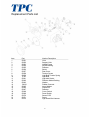
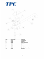
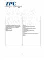
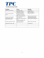
Lucent Operatory
Ceiling mount Dental Light
Operation and service manual
TPC
851 S. Lawson St
City Of Industry, CA 91748
P626-810-4337 Fax 626-810-4245
www.tpcdental.com
1
REV. 1-1-13
Table on Contents:
Page
GENERAL INFORMATION
Installation
3
4
Overview of components
5
Operation instructions
6
Light head and vertical arm adjustment
replacement of light bulb
7
8
Replacement Parts List
9
CLEANING & DISINFECTING GUIDE
12
Warranty
13
TROUBLE SHOOTING GUIDE
14
Technical Assistance is available Monday through
Friday, 8:00 Am to 5:00 PM PST.
2
General Information:
Definitions of symbols
Risk of electrical shock present. Make
sure power is disconnected before
attempting this procedure.
Type B equipment
Caution: Failure to carefully follow
the described procedure may result in
damage to the equipment or
operator.
Dangerous Voltage
AC (Alternating Current)
Off
Protective earth (Ground)e
On
against electrical shock)(Protected a
3
4
Operatory Light Installation
1.
2.
3.
4.
5.
6.
7.
8.
Secure mounting plate to the ceiling using supplied LAG bolts.
Route power supply through the center of the mounting plate.
Install the leveling nuts between the mounting plate and ceiling flange if not already attached.
Route the wire through drop post and Install the light post into the ceiling flange and secure it with the
provided roll pin.
Secure the light post to the ceiling flange by tightening the set screws.
Slide the flange cover and flange cover retaining ring up over the drop post and secure it in place.
Connect the incoming power lines to the 3 cord wire and secure it with wire nuts.
Install the light transformer housing to the drop post and attached it using only the supplied set screws.
See diagram below for plate and flange installation.
Operating Instructions
x
Move power switch to the left to set the light to high intensity. Move the power
switch back to the center position to turn it to the off position. Move the power
switch to the right to right to turn it to low intensity.
High
Low
Off
x
To adjust the position of the light, place your hand on the light handle and move
it to the desired location. You can move the light head up and down and left and
right. When turning the light head left and right it will stop, don’t force any
further movement of the light head as damage may occur.
x
To bring the light closer to the patient or desired illuminated location pull down
on the light handle to move the vertical arm. Once the light is in the desired
location I will stay in that positions until you move it back.
6
Light Head adjustment
x
x
If you experience a downward drift with your operatory light head please follow the
following procedure below.
Remove the nut cover shown in the image below. Tighten both retaining nuts on side
of the light head. See images below. To tighten the nuts turn them clockwise. Do not
over tighten the nuts as damage may occur.
Tension Nut
Vertical Arm adjustment
x
x
x
x
If you experience a downward drift with your operatory lights vertical arm please follow
the producer below.
Remove the end cap cover on the end of the vertical arm closest to the light head. This
requires a small Phillips screw driver.
Turn the nut located at the end of the light arm to adjust the tension.
Turn the nut clockwise to increase the tension. Turn the nut counter clockwise to
decrease the tension.
If your vertical light arm drifts down then you need to increase the tension. If the
vertical light arm drifts back up you need to decrease the tension.
x
7
Light Bulb Replacement Instructions.
1. Locate the rear cover to the operatory light and
remove the 4 Allen screws with a 3/32 Allen
wrench.
2. Locate the tension spring retainer. Once you
locate it press it in and rotate it counter
clockwise. These will UN lock the retaining spring
that holds in the light bulb.
3. Remove the wire that connects the light bulb to
the wiring harness “the red wire”. Replace the
light bulb with replacement light bulb part
number P709 or similar. Halogen lamp 12 Volts 55
Watts.
8
Replacement Parts List
Item
1
2
3
4
5
6
7
8
9
10
11
12
13
14
15
16
17
18
19
20
21
22
Part
56051
56052
56053
56054
56055
56056
56057
56058
56059
P709
56061
56062
56063
56064
56065
56066
56067
56068
56069
56070
56071
56072
Number Description
Yoke
Support Yoke
Handle Frame
Socket Bushing
Reflector
Shield
Rear Cover
Tension Covers
Light Bulb Tension Spring
Light Bulb
Light bulb Socket
Reflector Holder Bushing
Washer
Rubber Grommet
Large Washer
Round Nut
Deflector
Cover, Switch
Power Switch
Sensor PCB
Screw
Light Head Wire Harness
9
Item
1
2
3
4
5
6
7
8
9
10
Part Number
56001
56002
56003
56004
56005
56006
56007
56008
56009
56010
Description
Light Bushing
Rigid Arm
Cover, Transformer
Transformer
PCB Board
Fuse
Switch
Screw X 4
Transformer Cover Screw
Set Screw
10
Item
1
2
3
4
5
6
7
8
9
10
11
12
13
14
15
16
17
18
19
20
21
Part Number
56021
56022
56023
56024
56025
56026
56027
56028
56029
56030
56031
56032
56033
56034
56035
56036
56037
56038
56039
56040
56041
Description
Cover Flex Arm
Knuckle, Rigid Arm
Knuckle, Head
Spring Rod
Extension Support
Bushing
Bezel
Bushing
Block Spring Tensioner
Friction Block
Tensioner Rod
End Cap Cover
Retainer Ring
Long Pin
Retainer Ring Small
Short Pin
Retainer Ring Small
Spring
Screw Cap Head Socket
Screw, End Cap
Friction Screw
11
Cleaning and disinfecting guide
Table 1
*The Manufacturer makes no representation as to the disinfectant efficacy of these products.
We make no warranty expressed or implied that these disinfectants will not damage the
surface finishes. Damage and discoloration of the surface finishes are not covered under the
warranty. Iodophor based disinfectants will cause yellow staining on many surfaces. Regular
washing with soap and water will minimize this staining. Iodophor neutralizers such as
Promedyne are also available.
Unacceptable Disinfectants
These disinfectants will harm the surface
finishes of dental equipment and are not
recommended.
Use of these products will void your
warranty.
Chemical Composition / Trade Names
Strong Phenols / Lysol, Lysol 2, Lysol
Phenol Alcohol Professional, Coe Foam, Coe
combinations Spray Pump, Vitaphene, Omni II
Sodium Hypochlorite / Clorox, Ajax, Purex
Household Bleach
Alcohol
Household Cleaners
Conditionally Acceptable Disinfectants
These disinfectants have been found to be the
least
harmful to the equipment surfaces by our test
methods.
Chemical Composition Trade Names
Iodophors Biocide, Aseptic IDC,
Wescodyne, SD5, Promedyne,
Iodo Five
Mild Phenols Procide ES, Asepti Steryl
Aerosol
Glutaraldehyde / Sterall Spray, Coldspor
Phenol Sprays
Synergized Super Dis cide, Cavicide,
Kleenaseptic
Quat
Phenol/Water Sprays Top Cide, Sporicidin Pump
Spray
Birex se
12
Warranty Information
All of our products sold are guaranteed to be free from defects in workmanship and materials for a 1 year
from date of purchase, unless otherwise stated. TPC will repair or replace any defective part at no
charge. TPC will not be responsible for labor charges or shipping charges to / from the TPC facility. This
guarantee does not cover normal wear or stains on surface finish. The guarantee does not cover damage
resulting from improper installation, misuse or accidents incurred in shipping and handling. All claims
against the freight carrier must be initiated at the time the damaged items are received. The claim is the
responsibility of the customer. We are improving our products on a continuous basis. We reserve the right
to make modifications without the need for prior notification and are not obliged to modify previously
manufactured items. Light bulbs are not covered under any type of warranty. Only authorized service
technicians should attempt to service TPC equipment. Service performed by any unauthorized technician
may result in a voided warranty.
13
Troubleshooting Guide.
Problem
Cause
Solution
Light does not illuminate
No power to light
Light bulb has expired
Transformer is expired
Secondary windings on
transformers are expired
Main power switch is bad
Short or open in power line
form transformer.
Light head tension springs are
loose
Vertical arm tension spring
needs to be adjusted
Light post is not level
Check power
Replace light bulb
Replace transformer
Replace transformer
Only high or low function
works
Light turns on and off then
the light head is moved
Light head drifts down
Vertical arm drifts up or down
Light drifts from left to right
Replace main power switch
Check each power line for
short or open. Then replace.
Tighten light head spring nuts.
Adjust vertical arm tension.
Level light post.
14