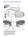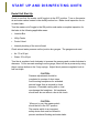
1
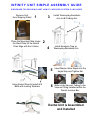
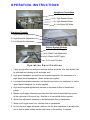
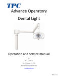
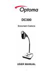
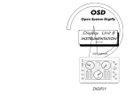
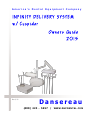
America’s Dental Equipment Company Rev 2/15 Dansereau (8 0 0 ) 4 2 3 - 5 6 5 7 / WWW.DHPDENTAL.COM D A N S E R E A U H E A LT H P R O D U C T S , I N C . AM ERIC A’S DENT AL EQU IPMENT COMPANY Dansereau Health Products, Inc has been manufacturing dental equipment for over 40 years. We have compiled a significant amount of data and information regarding the manufacturing, use and maintenance of dental equipment. Information contained in this manual will assist you in use and maintenance of your Dansereau equipment. We offer the most comprehensive 10 year warranty on USA manufactured dental equipment today. Our customer service department is the most progressive within the dental industry with an ever growing series of support documents and video available thru E-mail and the Internet. They are easily accessible and completely descriptive for the dentist, staff or any technician to use in the long term support of Dansereau Health Products, Inc. SUPPORT ACCESS Dansereau Health Products, Inc. 1581 Commerce Street Corona, CA 92879 Toll Free (800) 423-5657 (951) 549-1400 Fax (951) 549-1411 Website-WWW.DHPDENTAL.COM TESTING LABORATORIES ETL Testing Lab.- Report #530937 Medical and Dental Equipment Category - 6 -UL 544 - 2nd Ed. CAN/CSA Testing Laboratories- Report #531003 Canadian Standard for Medical Electrical Equip. No 601.1 - M90 US Food and Drug Administration Medical Device Registry - #202716 DENTAL UNIT SPECIFICATIONS: No Electrical Components are installed in the Dental Unit. Dental Unit Weight: 97lbs IEC Medical Device Classification Classification 2A Type B Operation Mode: No Electric in Dental Unit Splash Protection IPX4 Maximum Torque of Accessory Items 60lbs / ft. (81 N-m) D A N S E R E A U H E A LT H P R O D U C T S , I N C . AM ERIC A’S DENT AL EQU IPMENT COMPANY TECHNICAL DESCRIPTION: The dental delivery system is a combination of dental equipment components used to carry, position and control the devices used in the practice of dentistry. Delivery systems provide handpiece connections that deliver air, water and vacuum to the patient. Delivery systems generally have several components, all are needed to provide dentistry, including a control head, cuspidor system, assistants utilities, and a junction box. Delivery systems can be mounted to the wall, cabinet, dental chair or a mobile cart. Air, water, vacuum, drain and generally enter the system through the junction box. Shut-off valves, and pressure regulators are located in the junction box. Tubing delivers air, water and vacuum to the control head for operating pneumatic items. The control head contains adjustment knobs for controlling handpiece pressure, and the amount of coolant air and water. The dentist controls the rate and flow through the pressure applied to the foot control or syringe buttons. The dental chair is classified as a Class 2A product under rule 11 of Annex IX of the MDD 93/42/EEC: accordingly, the provisions of Annex II apply. NOTE: Regarding International Electrical Specification: Dansereau does not supply provisions for international power requirements. This will be configured by the equipment dealer in the country of destination. SAFETY AND IDENTIFICATION MARKINGS: D E N TAL U N I T S TAN D A R D S & M AI N T E N AN C E HANDPIECE COMPATIBILITY: This delivery system is designed to be compatible with air driven (pneumatic) handpieces that conform to ISO 13294. The air driven (pneumatic) handpieces, tubing and connectors are available in either 4 hold Midwest or 3 hole Borden tubing, other configurations are available under special order. The end user (dentist) will have specified the preferred type of connection during ordering. It is the responsibility of the end user (dentist) to procure appropriate handpieces to work with the handpiece connections specified at time of order confirmation. Certain countries may have particular regulations regarding which handpieces are acceptable for use: e.g. countries in the European Union require handpieces which meet the requirements of the medical devices Directive 93/42/EEC. NOTE: Regarding International Electrical Specification: Dansereau does not supply provisions for international power requirements with the dental unit. SUGGESTED TOOLS: Allen Wrench Set 9/16” Socket Wrench 7/16” Open End Wrench Chanell Locks 1/2” Socket Wrench REPLACEMENT PARTS: The following represents a condensed list of maintenance parts that may be used during the normal lifespan of the dental unit. Contact Dansereau direct for a complete list of additional parts - (800) 423 - 5657. Master Shut Off Valve Filter #DA1238B Saliva Ejector Tip (QTY 5) #DA1284-2 Amalgam Trap Solids Filter (QTY 10) #DA1234 Amalgam Trap Mounting Bracket #DA1231 D E N TAL J U N C T I O N B O X C O N N E C T I O N S Local building codes and regulations may require licensed plumbers and electricians to install utilities. Make sure all plumbing conforms to prevailing local building codes and regulations. Air Supply from Compressor: 1/2” pipe NPT protruding 1” from floor or wall with 1/2” x 3/8” compressor fitting angle stop required. Supplied by contractor. Air pressure from dental air compressor operating range 80 to 100 PSI. Air from dental air compressor must be clean and dry. Air plumbing lines must be flushed clean before making final dental junction box connects. Water Source: 1/2” pipe NPT protruding 1” from floor or wall with 1/2” x 3/8” compressor fitting angle stop required. Supplied by contractor. Water Pressure Operating Range 40 to 80 PSI. Water plumbing lines must be flushed clean before making final dental junction box connects. Electrical: 1/2” conduit and box with duplex outlet supplied by contractor. Wire electrical box as per code. Horizontally no higher than 4 “ from finished floor. .Central Vacuum: Vacuum system plumbing specifications to be supplied by central vacuum system supplier. Terminate in the dental junction box according to dental junction schematics. Confirm line sizes with central vacuum system supplier. Gravity Drain (Cuspidor): 1” Tube protruding 1” from finished floor. NOTE: Conform to local building codes, Vented plumbing trap is required. I N F I N I T Y U N I T S I M P L E A S S E M B LY G U I D E D I S R E G AR D T E L E S C O P I N G AS S T AR M I F C U S P I D O R S Y S T E M I S I N C L U D E D Remove Unit from Shipping Pallet 1 Place the Mounting Plate Under the Steel Plate for the Dental Chair Align with the 5 Holes Using Socket Wrench Install all 5 Bolts with Locking Washers 3 Install Telescoping Assistants Arm on Bi Folding Arm 4 Install Amalgam Trap on Telescoping Assistants Arm 2 5 Insert Master Valve Nipple into the Angle Stop and Tighten Nut 6 Slide on the Vacuum Tubing to the Vacuum Fitting installed within the Dental Junction Box Dental Unit is Assembled and Installed O P E R AT I N G I N S T R U C T I O N S Handpiece Connections 1) 3 Way Syringe 2) High Speed w/Water 3) High Speed w/Water 4) Low Speed No Water Handpiece Controls 1) High Speed Air Adjustment 2) High Speed Air Adjustment 3) Low Speed Air Adjustment Delivery System Controls 1) Master On/Off Toggle 2) Water Flow Adjustment 3) Water On/Off Toggle 4) Air Lock Flex Arm Operation Specifications 1. 3 way syringe offers two buttons to activate and air and water flow, both buttons can be activated and creating an air and water mist. 2. High speed handpiece connections are threaded connection for attachment of a high speed dental handpieces. Water and air are supplied. 3. Low speed handpiece connection is a threaded connection for attachment of a slow speed dental handpiece. Air is only supplied. 4. High and low speed adjustments increase or decrease air flow to dental handpieces. 5. Master on/off toggle extremely important item that turns off dental delivery system at the conclusion of the work day. Must be on to use dental delivery system. 6. Water flow adjustment increases or decreases water flow to handpieces 7. Water on/off toggle turns on or off water flow to handpieces. 8. Air lock flex arm toggle activated a brake in the flex arm mechanism to allow the flex arm to hold a stable vertical position with items on the unit tray, if required. I N F I N I T Y C U S P I D O R O P E R AT I O N Ceramic Top of Cuspidor Ceramic Lower Front of Cuspidor Water Quick Disconnect Left Side Under side of Cuspidor Left Side Under side of Cuspidor Cuspidor Rinse Timer Adjustment Valve Amalgam Cannister Cuspidor Rinse Bowl Activation Button Ceramic Bowl Mounting Screws Cup Filler Rinse Bowl Activation Button NOTE: To Remove Cuspidor Bowl and access internal components, remove Ceramic Mounting Screws, firmly grasp the Ceramic Bowl and rotate bowl side to side while pulling up. Bowl will work loose from Drain Housing. Lay the Bowl to the side while working on internal components. Cuspidor Rinse Bowl Activation Button Cuspidor Rinse Water Flow S TA R T U P A N D D I S I N F E C T I N G U N I T S Dental Unit Start Up Check to see that the master on/off toggle in in the OFF position. Turn on the master air and water valves located in the dental junction box. Make visual inspection for air or water leaks. Turn the master on/off toggle to the ON position and make a complete inspection for the leaks in the following applicable areas: Junction Box Utility Center Control Head Internal plumbing of the control head Check air and water pressure on the junction box gauges. The gauges must read Air: 75 to 80 psi Water: 35 to 40 psi Turn the air regulator knob clockwise to increase the pressure and counterclockwise to decrease. For an accurate reading from the gauge, bleed off the air pressure by using the air syringe button on the 3 way syringe. Adjust the air pressure regulator knob in half turn steps. CAUTION: Pressure adjustments should be completed in a series of short steps. Avoid running handpieces for extended periods longer than is required to check pressure. Extended running with no load can damage the handpiece. No handpiece should ever be run without a bur in the chuck. CAUTION: When not in use, the master switch should be left in the OFF position. The master switch is an important safety device that must be utilized to prevent accidental flooding and water leaks. S T E R I L I Z AT I O N T E C H N I Q U E S Infection control in the dental facility continues to be a high priority for all staff working within the dental office. OSHA, the ADA and CDC are all involved in this complex issue. Dansereau will not attempt to specify the required intervals for disinfection nor can they recommend the overall best surface disinfectant. You can refer to the appropriate organizations for more information on disinfecting your dental equipment. Techniques: Barrier Technique: Dansereau does advocate the barrier technique whenever possible. The use of disposable barrier’s, with changes between patients, will ensure the finish and appearance will be preserved. Chemical Disinfection: If chemical disinfection is the disinfection method of choice it is imperative that a mild soap and warm water be used once per day to mitigate the residual effects of chemical disinfection solutions. When using chemical disinfection solutions always pay strict attention to use detail, including appropriate measurements when using concentrated disinfection solutions. disinfection solutions, used in the recommended strength, can be relatively harmless to surfaced of dental equipment. Unacceptable Disinfectants Disinfectants with the following compositions will harm the surface finishes of dental equipment and are not recommended Use of these products will void your warranty. Conditional Accepted Disinfectants Disinfectants with the following compositions have been found to be the LEAST HARMFUL to equipment surfaces by our test methods. Chemical Composition Chemical Composition Strong Phenols/ Phenol-Alcohol Combinations Sodium Hypochlorite/ Household Bleach Alcohol / Alcohol Based Wipes Iodophors *** Mild Phenols Household Cleaners Phenol / Water Sprays Glutaraldehyde / Phenol Sprays Synergized Super Quat Damage and discoloration of the surface finishes caused by disinfectants are NOT covered by warranties. Iodophor-based disinfectants will cause yellow staining on many surfaces. Regular washing with soap and water will minimize this staining. Iodophor neutralizers such as Promedyne are also available. WA R R A N T I E S Dansereau has the most comprehensive product warranty programs available to the dentist today. We offer a 10 Year Warranty on our Dental Chairs and Delivery Systems with complete features listed below: 3 Years 100% / 4-10 Years Prorated Annually Delivery System Internal Tubing (against leaks), Master Valve Regulators, Handpiece Control Blocks (Not Gaskets), Light Posts, Automatic Handpiece Holders, Delivery System Water and Air Flow Control Valves, Stool Cylinders, Manual Chair Switches, Delivery System Flex Arm, Delivery System Telescoping Arm, Cuspidor Frame. 1 Year 100% Diamond Dental Light, Chair Foot Control, Stool Ring, Stool Seat, Stool Casters, Circuit Board and Prepositioning Switches. 6 Months 100% Base and Unit Cover parts, 3-way syringes, Delivery System Foot Control and Fiber Optics Systems. 30 Days 100% Dental Light Bulbs, Fiber Optic Light Bulbs, X-ray View Box Light Bulbs. Broken or User Damaged Items are Not Covered under Warranty. Minimum Maintenance is required in order to guarantee full use of warranties All dental delivery systems require clean dry air to allow the proper lifespan to the micro valves within the dental delivery system. If your air compressor does not have an adequate drying and filtration system the warranties of the micro valves, on/off toggle valves, relays, regulators, master valves, foot controls, 3 ways syringes and automatic blocks may be void. GUARANTEE Dansereau will guarantee against defects in material and workmanship. Defective parts will be repaired or replaced: no claim for labor or consequential damages will be allowed. All replacement parts claimed defective will be filled in the usual manner, such invoice being subject to adjustment after the alleged defective material has been returned and inspect by the manufacturer. The warranty does not cover damage resulting from improper installation, maintenance, accident or misuse.