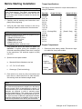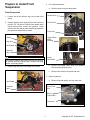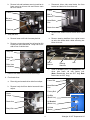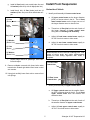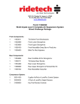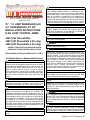
1
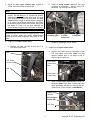
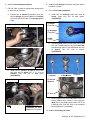
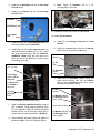
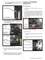
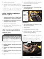
WARNING
This kit should only be installed on a vehicle that is in
good working condition. Before you install the kit, thoroughly inspect the vehicle for corrosion or deformation
of the sheet metal. If the vehicle is suspected to have
been in a collision or misused, do not install this kit.
Off-road use of your vehicle with this kit installed may
increase the stress applied to the factory body mounts.
Failure to observe this warning may result in serious
personal injury and/or severe damage to your vehicle.
3651 N. Hwy. 89 • Chino Valley, AZ 86323
(928) 636-7080
‘07 - ‘12 JEEP WRANGLER (JK)
4.5” SUSPENSION LIFT KIT
INSTALLATION INSTRUCTIONS
FLEX JOINT CONTROL ARMS
WARNING
Many states and municipalities have laws restricting
bumper heights and vehicle lifts. Consult state and
local laws to determine if the changes you intend to
make to the vehicle comply with the law.
WARNING
The installation of larger tires may reduce the effectiveness of the braking system.
J4614 (No Driveshafts)
J4615 (W/ Driveshafts 2 Dr only)
J4616 (W/ Driveshafts 4 Dr only)
WARNING
Before you install this kit, block the vehicle tires to prevent the vehicle from rolling.
REFER TO INSTRUCTIONS PACKAGED WITH
DRIVESHAFTS FOR PROPER INSTALLATION
WARNING
We strongly recommend using the Performance Automotive Group shocks that were engineered to be used
with this system. If you use other shocks, they must
match the full extended and full collapsed lengths of
the Performance Automotive Group units exactly. The
use of longer or shorter shocks than recommended
may cause damage to the vehicle suspension and
could result in sudden loss of control of the vehicle and
personal injury. Contact Performance Automotive
Group for the lengths of the front and rear shocks that
must be used with this suspension system.
-Drive Shafts Are Only Avalible for 07-11 JK’s*2012 Model Requires Exhaust Modifications*
WARNING
Installation of a Performance Automotive Group suspension lift kit will change the vehicle’s center of gravity
and handling characteristics both on- and off-road. You
must drive the vehicle safely! Extreme care must be
taken to prevent vehicle rollover or loss of control,
which could result in serious injury or death. Avoid sudden sharp turns or abrupt maneuvers and always make
sure all vehicle occupants have their seat belts fastened.
NOTE
Performance Automotive Group recommends using
the Loctite® on the threads of all kit nuts and bolts
unless specified otherwise in these instructions.
WARNING
NOTE
Before you install this kit, read and understand all
instructions, warnings, cautions, and notes in this
instruction sheet and in the vehicle owner’s manual.
Installation of a suspension lift will change the driveline
angles which may cause a noticeable vibration in the
vehicle. See the troubleshooting section at the end of
these instructions.
CAUTION
Proper installation of this kit requires knowledge of the
factory recommended procedures for removal and
installation of original equipment components. We recommend that the factory shop manual and any special
tools needed to service your vehicle be on hand during
the installation. Installation of this kit without proper
knowledge of the factory recommended procedures
may affect the performance of these components and
the safety of the vehicle. We strongly recommend that
a certified mechanic familiar with the installation of similar components install this kit.
WARNING
The suspension travel on the Jeep is limited by the
shocks. The use of shocks other than those specified
for this type of lift may allow for greater suspension
travel causing adverse effects or vehicle component
damage.
WARNING
DO NOT combine suspension, body, or other lift
devices. Use of vehicle with combined lifts may result
in unsafe and/or unexpected handling characteristics.
WARNING
Always wear eye protection when operating power
tools.
1
Wrangler JK 4.5” Suspension Lift
Before Starting Installation
Torque Specifications
See factory service manual for torque values when reusing OE fasteners.
WARNING
Factory wheels will no longer fit with out 1.25” or
larger wheel spacers. Trail master recommends that
you use 4.5” backspace wheels or less with this kit.
This will allow extra clearence between the wheels the
control arms.
Bolt Size
Grade 5 (ft.-lbs.)
1/4”-20
10
1/4”-28
10
5/16”-18
17
5/16”-24
20
3/8”-16
30
3/8”-24
35
7/16”-14
50
7/16”-20
55
1/2”-13
75
1/2”-13 (Carriage Bolt)
38
1/2”-20
55
9/16”-12
105
9/16”-18
115
5/8”-11
150
5/8”-18
160
3/4”-16
175
1. Carefully read all warnings and instructions completely before beginning.
2. Verify all parts have been received in this kit by
checking the parts list at the end of this document.
NOTE
If parts are missing from kit, please be prepared to provide the following information:
1. Name of purchase location
2. Bar Code on side of box
3. Date above bar code
4. Date inside box cover
5. Inspector # from inside box cover
Grade 8 (ft.-lbs.)
10
12.5
22.5
25
40
45
65
70
100
(Grade 2 Only) N/A
70
135
150
195
210
225
Engine Compartment
3. Only install this kit on the vehicle for which it is
specified. If anytime during the installation you
encounter something different from what is outlined
in the instructions, call technical support at (928)
636-3175.
1. Disconnect both battery cables. Disconnect negative cable first, then positive cable.
Battery
4. Special tools and parts needed:
Negative
Cable
a. Standard & Metric Mechanics tool set.
b. 1/2”, 7/16” & 3/8” drill bit
Positive
Cable
c. Grease gun (Track bar bushing)
5. Park vehicle on a clean, dry, flat, level surface and
block tires so vehicle cannot roll in either direction.
Set steering wheel and wheels straight ahead.
NOTE
Adhere to recommendations when replacement fasteners, retainers and keepers are called out in the factory
service manual. When re-assembling the vehicle it is
recommended by the vehicle manufacturer that certain
fasteners are replaced in order to maintain proper
retention characteristics. This system may not include
all replacement hardware as recommended by the factory service manual. Additional replacement hardware
should be obtained prior to installation of this system to
meet the requirements of the factory service manual.
2
‘Wrangler JK 4.5” Suspension Lift
Prepare to Install Front
Suspension
4. Front shock absorbers
a. Remove lower shock mounting bolts.
Front Suspension
Shock Perch
1. Loosen, but do not remove, lug nuts on each front
wheel.
Front Shock
2. Using a hydraulic jack, slowly lift front axle until front
tires are 3-5” off ground. Position jack stands under
frame behind lower control arm perches. Lower
vehicle onto jack stands while maintaining hydraulic
jack pressure underneath front axle.
Front Axle
Upper Shock
Nut &
Bushing
Wheel
Lug Nuts
Jack Stand
Hydraulic
Jack
Lower
Shock Bolt
WARNING
Use extreme caution when lifting vehicle from ground.
To prevent serious personal injury, ensure the lifting
device is securely placed.
b. Remove two upper shock nuts, four washers
and two bushings from perch.
3. Remove lug nuts and front wheels from vehicle.
c. Remove two shocks from perch and axle.
5. Remove track bar
a. Remove bolt and captive nut from front axle.
Jack Stand
Front Track
Bar
Hydraulic
Jack
Bolt &
Captive Nut
Front Axle
3
‘Wrangler JK 4.5” Suspension Lift
b. Remove bolt and hardware securing track bar to
frame mount on drivers side and remove track
bar from vehicle.
c. Disconnect driver side metal brake line from
bracket and brake line from frame rail.
Frame
Frame
Bolt &
Bracket
Bolt and
hardware
Metal Brake
Line
Brake Line
Track bar
d. Remove bolt, brake line and bracket from frame
rail.
6. Sway bar links
a. Remove lower nut & bolt from sway bar link.
e. Remove steering stabilizer from original mount
on axle, also loosen both u-bolts secureing stabilizer to tie rod..
b. Remove nut securing upper joint of sway bar link
to sway bar and remove link. Keep link to reinstall at rear of vehicle later.
Sway Bar
Sway Bar
Link
Bolt &
Bracket
Bolts, Nuts
& Washers
f.
7. Remove four bolts from front drive shaft flange.
Steering
Stabilizer
Axle
Install kit bracket (Brake line BHBAG903) onto
driver side frame rail with factory bolt.
(Note: Front brake lines are 25.5” long. Rear
brake lines are 22.5” long.)
8. Front brake lines
Frame Rail
a. Place drip pan beneath driver side front caliper.
Metal Brake
Line
b. Remove banjo bolt from brake hose and brake
caliper.
Factory Bolt
Brake
Caliper
Kit Clip
(Brake Line)
Brake Line
Kit Bracket
(Brake Line)
Banjo Bolt
Kit Line
(Brake)
4
‘Wrangler JK 4.5” Suspension Lift
Install Front Suspension
g. Install kit line (brake) onto metal brake line and
kit bracket (brake line) with kit clip (brake line).
Underside of Vehicle
h. Install banjo bolt, kit line (brake) and two kit
washers (brake line) onto driver side brake caliper.
1. Identify and Assembly kit Lower control arms
a. Kit lower control arms are the larger diameter
(1.75”) of the two sizes in the kit. The kit front
lower control arms are the longer two out of
the larger diameter ones to choose from.
Kit Line
(Brake)
Brake
Caliper
b. Thread one kit flex joint into the end of each of
the larger diameter kit lower control arms
along with a kit bushing end assembly.
Banjo Bolt
c. Adjust kit front lower control arms equally to
23-3/8” from hole center to hole center.
Kit Washer
(Brake Line)
d. Adjust kit rear lower control arms equally to
20-7/8” from hole center to hole center.
Kit Line
(Brake)
NOTE
Measurements are to be used as a starting point. Fine
tuning of pinion angle and caster measurements
should be done during alignment after install is
complete.
Kit Washer
(Brake Line)
i.
Repeat steps above for passenger side brake
line and caliper.
Kit Front Lower
Control Arm
9. Remove skidplate secured with three bolts under
transmission located right behind front lower control
arm mounts.
10. Using jack carefully lower front axle to remove front
coil springs.
Kit Rear Lower
Control Arm
2. Identify and Assembly kit Upper control arms
a. Kit Upper control arms are the smaller diameter (1.5”) of the two sizes in the kit. The kit front
upper control arms have the bracket end
welded to them.
b. Thread one kit flex joint into the end of each of
the smaller diameter kit upper control arms.
c. Adjust kit front upper control arms equally to
19-3/16” from hole center to hole center.
5
‘Wrangler JK 4.5” Suspension Lift
3. Adjust kit rear upper control arms equally to
18-5/8” from hole center to hole center.
b. Install kit lower control arm with flex joint
mounting at differential. Secure using O.E.
hardware Do not torque at this time.
NOTE
The Flex Joints are unique when it comes to
service. We do not use or recommend grease!
Grease attracts more dirt and debris then it is worth
while doing more harm to the joint itself. Our Flex
Joints are also to tight for grease which is designed
to be used in flow through application. We simply
recommend removing the service screw, putting in a
few drops of 3 and 1 oil and then replacing the
service screw everytime you perform an oil change.
NOTE
Measurements are to be used as a starting point. Fine
tuning of pinion angle and caster measurements
should be done during alignment after install is complete.
kit bushing joint
4. Install front kit lower control arms.
kit Lower
control arm
kit flex joint
c. Repeat on passenger side of vehicle.
a. Remove two bolts securing Driver’s side O.E.
front lower control arm.
5. Install front kit upper control arms.
a. Remove two bolts securing Passenger’s side
O.E. front upper control arm. (Note: You may
remove exhaust pipe or cut head of bolt to
remove upper frame bolt.)
Bolt
O.E. Lower
Control Arm
Front Upper
Control Arm
Bolt.
Bolt
Front Upper
Control Arm
b. Install kit front upper control arms using O.E.
hardware. (Note: If you have cut the head of the
upper passenger side bolt you can use the provided kit bolt. 12mm x 80mm in J4614BAG1)
kit Bolt (12mm
x 80mm)
kit Front Upper
Control Arm
O.E. Bolt
6
‘Wrangler JK 4.5” Suspension Lift
6. Install kit front bumpstop spacers.
8. Install kit coil springs into position and raise axle to
hold them in place.
7. Drill 3/8” hole in center of raised lower spring perch
on each side of front axle.
9. Front kit track bar installation.
a. Position two kit spacers (bumpstop, front) into
two kit springs (coil) and install two kit springs
(coil) onto axle with ends of kit springs against
stops.
a. Install two kit bushings (track bar) and kit
sleeve (track bar) into kit bar (track).
(J4611BAG2)
Kit Sleeve
(Track Bar)
Kit Spacer (Bumpstop, Front)
Kit Bushings
(Track Bar)
Kit Bar
(Track)
b. Thread kit joint (heim) into track bar with kit nut
(3/4” jam). Install Heim joint end of kit track bar
into passenger side of front differential with two
kit spacer. Use O.E. bolt to secure.
(J4611BAG2)
Kit Spring (Coil)
Coil Stop
b. Install two kit spacers (bumpstop, front) onto
axle with two kit bolts (3/8” x 3”), four kit
washers (3/8”) and two kit nuts (3/8”)
(J4614BAG1).
kit Spacer
kit Heim Joint
kit Spacer
kit Track bar
& Spacers
Kit Spring (Coil)
O.E. Bolt
Axle
c. Zip tie opposite end of kit Track bar to frame. It
will be installed once vehicle is on the ground.
(Note: Eye to eye lenght may be set to 32.75” as
a starting point. Axle will have to be centered
before alignment is completed.)
Kit Bolt (3/8” x 3”),
Kit Washers (3/8” SAE),
Kit Nut (3/8”-16 Stover)
10. Install kit front sway bar links
7
‘Wrangler JK 4.5” Suspension Lift
a. Install four kit bushings onto four kit front sway
bar link halves.
h. Note: Torque kit hardware (1/2-13 2 1/2”
Carriage Bolt) to 38 ft lbs.
b. Install two kit sleeves into four kit front sway
bar link halves.
Kit sleeve
Kit Bushing
Bolt & Bracket
Bolts
Steering Stabilizer
11. Reinstall four bolts into front drive shaft flange.
kit swaybar
link
12. Install kit front shocks.
a. Install two kit bushings & sleeves into front
shocks.
c. Install short half of kit front sway bar link onto
axle using OE hardware. (JKD4614)
b. Install two kit boots (shock) onto two kit absorbers (shock, front) with two kit ties (zip).
d. Install long half of kit front sway bar link onto
sway bar end using kit bolt (1/2” x 2-3/4”), large
and small spacers along with the hardware.
(JKD4614). (Note: Sway bar may need to be
drilled out with a 1/2” drill bit for proper fitment
of hardware provided.)
Kit Boot
(Shock)
Kit Tie
(Zip)
Kit Bolt
(1/2” x 2-3/4”)
Kit Absorber
(Shock,
Front)
Install larger
spacer against
sway bar
c. Install two kit absorbers (shock, front) into
upper shock perches with four kit washers
(shock), four kit bushings (shock, front, upper)
and two kit nuts (shock, front).
& small spacer
on outside of
heim joint
Kit Nut
(Shock)
Kit Front
Sway Bar
Link.
e. Do not tighten hardware at this time.
Kit Washer (Shock),
Kit Bushing (Shock,
Front, Upper)
f.
Upper Shock Perch
Install kit steering stabilizer bracket using kit
(3/8”) hardware. Install steering stabilizer using
kit (1/2”) hardware. Flip OE steering stabilizer
bracket (On tie rod) so that the U-bolts are no
longer under the steering stabilizer. (JKS4614)
Kit Washer (Shock),
Kit Bushing (Shock,
Front, Upper)
g. Adjust stabilizer to proper length and tighten kit
hardware. (Note: Check for binding & adjust)
8
‘Wrangler JK 4.5” Suspension Lift
Prepare to Install Rear
Suspension
d. Line up kit front shock with lower shock mount
and raise differential till holes align. Secure
using OE hardware.
Rear Suspension
1. Loosen, but do not remove, lug nuts on each two
rear wheels.
Kit Front shock
2. Using a hydraulic jack under rear differential, slowly
lift rear axle until rear tires are 3-5” off ground. Position jack stands under frame just forward of lower
control arm perches. Lower vehicle onto jack stands
while maintaining hydraulic jack pressure underneath rear axle.
O.E. lower shock
mount hardware
Rear Axle
13. 2007-2010 Models: Reinstall Transmission skidplate using three kit spacers & bolts (12mm x
60mm). (J4614BAG1)
Jack Stand
kit Spacer &
Bolt
Hydraulic
Jack
Skidplate
3. Remove lug nuts and rear wheels.
4. Rear brake lines
kit Spacer &
Bolt
a. Place drip pan beneath driver side rear brake
caliper.
Frame Rail
b. Remove banjo bolt from brake hose and brake
caliper.
kit Spacer &
Bolt
Brake
Caliper
Skidplate
Brake Line
14. Install front wheels and lug nuts.
Banjo Bolt
15. Install front Driveshaft if working with J4615SSV or
J4616SSV. Refer to instructions supplied with driveshaft.
16. Using hydraulic jack, raise front of vehicle and
remove jack stands. Lower front of vehicle onto
ground and torque lug nuts to factory specification.
9
Wrangler JK 4.5” Suspension Lift
c. Disconnect driver side metal brake line from
bracket and brake line from frame rail.
g. Install banjo bolt, kit line (brake) and two kit
washers (brake line) onto driver side brake caliper.
Frame
Kit Line
(Brake)
Bolt &
Bracket
Brake
Caliper
Metal Brake
Line
Brake Line
Banjo Bolt
d. Remove bolt, brake line and bracket from frame
rail.
Kit Washer
(Brake Line)
e. Install kit bracket (Brake line BHBAG903) onto
driver side frame rail with factory bolt. (Note:
Front brake lines are 25.5” long. Rear brake
lines are 22.5” long.)
Kit Line
(Brake)
Kit Washer
(Brake Line)
Frame Rail
5. Repeat steps above for passenger side brake line
and caliper.
Metal Brake
Line
6. Shock absorbers
Factory Bolt
a. Remove lower mounting bolt on both rear shock
at axle housing.
Kit Clip
(Brake Line)
Kit Bracket
(Brake Line)
Rear Axle
Kit Line
(Brake)
Rear Shock
f.
Install kit line (brake) onto metal brake line and
kit bracket (brake line) with kit clip (brake line).
(Note: You may also leave brake line disconnected from frame at this time. This will help you
install the rear coils if you do not have a coil
spring compressor to install the rear coils.)
Bolt & Nut
10
Wrangler JK 4.5” Suspension Lift
b. Remove two upper bolts from both rear shocks
and remove.
a. Remove OE upper control arms on driver &
passenger side of vehicle. (Note: Support axle.)
Frame
Upper Control
Arm
Rear Shock
Bolts
Lower Control
Arm
7. Remove rear track bar
NOTE
a. Remove bolt and captive nut securing track bar
to axle. .
Refer to first 2 steps in front installation for identification of control arm lengths and placement if needed.
b. Install kit rear upper control arms. Flex Joint
goes to axle end. .
Trackbar
Kit Rear
Upper Control
Arm
Bolt
Axle Housing
Kit Rear Lower Control
Arm
WARNING
Compressed coil springs can expand violently causing
serious personal injury. Before removing the coil
springs, lower the axle housing as far as possible to
allow the coil springs to expand. Use caution when
using coil spring compressors.
c. Repeat to lower control arms. Use OE hardware
& tighten all control arm bolts at this time.
2. Install kit rear bumpstop blocks.
8. Carefully lower axle until rear coil springs are loose
and remove from vehicle.
a. Install kit rear bumpstop blocks onto rear
bumpstop contact pad located on axle next to
spring. Tab on kit rear bumpstop blocks faces
rearward on vehicle. Secure using kit bolt (5/16
x 3/4) & hardware. (J4614BAG1)
Install Rear Suspension
Rear Suspension
OE Track
bar
1. Install kit Control Arms.
Kit Rear
Bumpstop
Block
Rear Axle
11
Wrangler JK 4.5” Suspension Lift
b. Repeat on opposite side of vehicle.
a. Using kit track bar bracket as template, drill a
7/16” hole into factory track bar mount.
3. Install two kit springs (coil, rear) tiny pig tail wrap
goes to bottom.
OEM Track
Bar Bracket
Frame
Drill 7/16” Hole.
Kit Spring
(Coil, Rear)
Rear Axle
Rear Axle
b. Install kit Rear track bar bracket using
supplies hardware and spacer into stock track
bar & control arm mount location. (J4611BAG2)
NOTE
trail master recommends using rear JK coil spring
perch SP0400 (*Welding requiered*) for proper
spring perch clocking after your pinion angle is
adjusted to the proper degree. Replacing your coil
spring perches will eliminate comon rear spring arching. Sold separately.
c. Install OEM track bar into kit bracket on rear
axle using OE hardware to secure it.
Kit Bracket OEM
hardware
(Track Bar, Rear)
4. Install kit Rear park cable bracket
7/16” bolt &
washer
a. Use OE hardware to bolt the kit bracket to the
body. Use kit hardware (5/16”) to bolt parking
cables to kit bracket. (J4614BAG1)
3/8” bolts &
washers
Kit Spacer &
14mm bolt
(Track Bar, Rear)
Parking Cable
Bracket
d. Zip tie frame end of kit rear track bar to frame
mount for now. Track bar will be installed once
vehicle is lowered to ground.
5/16” Hardware.
Parking Cables
6. Install kit rear shocks.
5. Install kit Rear track bar bracket
12
Wrangler JK 4.5” Suspension Lift
a. Install two kit bushings (shock, rear) and two kit
sleeves (shock, rear) into body end of two kit
absorbers (shock, rear).
d. Install two kit absorbers (shock, rear) onto axle
with two factory bolts and captive nuts.
Kit Absorber
(Shock, Rear)
Kit Bushing
(Shock,
Rear)
Rear Axle
Kit Sleeve
(Shock,
Rear)
Bolt &
Captive Nut
Kit Absorber
(Shock,
Rear)
e. Install two kit absorbers (shock, rear) onto
frame rails with four factory bolts.
b. Install two kit bushings (shock, rear) and two kit
pins (bar, rear) into piston eyelet of two kit
absorbers (shock, rear).
Frame
Bolts
Kit Pin
(Bar, Rear)
Kit Absorber
(Shock, Rear)
Kit Absorber
(Shock, Rear)
Kit Bushing
(Shock, Rear)
c. Install two kit boots (shock) onto two kit absorbers (shock, rear) with two kit ties (zip).
7. Rear sway bar
a. Install kit rear swaybar brackets to flat plat
located just below and behind the rear upper
control arm axle mount. Secure using kit bolt
(7/16” x 1”) and hardware. (J4614BAG1)
Kit Boot
(Shock)
Kit Absorber
(Shock,
Rear)
b. Install OE front sway bar link in place of rear
sway bar link with lower going through kit
bracket just installed.
Kit Tie
(Zip)
kit Rear Upper
Control Arm
OE Front
Swaybar link
kit Rear Sway
Bar Bracket
13
Wrangler JK 4.5” Suspension Lift
8. Install rear wheels and lug nuts.
6. Verify brake fluid reservoir is full. Add brake fluid
according to manufacturer’s specifications.
9. Install rear Driveshaft if working with J4615SSV or
J4616SSV. Refer to instructions supplied with driveshaft.
Engine Compartment
1. Connect both battery cables. Connect positive cable
first, then negative cable.
10. Using hydraulic jack, raise rear of vehicle and
remove jack stands. Lower rear of vehicle onto
ground and torque lug nuts to factory specification.
Battery
Finish Track Bar Installation
Front and Rear
Negative
Cable
1. Thread front track bar in or out as needed until bolt
hole at frame lines up. Secure using OE hardware.
Positive
Cable
2. Use calibrated eye to ensure that front and rear differentials are centered under vehicle.
Miscellaneous
3. Repeat at rear of vehicle and tighten.
1. Apply kit label (warning) onto dashboard in plain
sight of all vehicle occupants.
4. Have vehicle aligned. Shop should center axles
during alignment process.
2. Adjust headlights.
3. Check all fasteners to ensure they are tight.
After Completing Installation
4. Ensure all wires, hoses, cables, etc. are properly
connected and there is ample slack.
Bleed brake system
WARNING
5. Align vehicle to OE specifications. Retain alignment
results.
Before driving the vehicle, pump the brakes several
times. If the pedal is soft or mushy, refer to the vehicle
service manual and verify the brake bleeding procedures. Failure to do so may cause the brakes to malfunction, resulting in property damage or serious
personal injury.
**NOTE: 2012 Models (with 3.6L motor) will require
exhaust modifications, to cross pipe, in order to clearance front drive shaft as shown below:
Cross Pipe Spacer Installed
Drive Shaft
1. Verify brake fluid reservoir is full.
2. Bleed rear passenger side brake caliper at brake
bleeder fitting.
3. Bleed rear driver side brake caliper at brake bleeder
fitting.
4. Bleed front passenger side brake caliper at brake
bleeder fitting.
5. Bleed front driver side brake caliper at bleeder fitting.
14
Wrangler JK 4.5” Suspension Lift
Dynamic Vehicle Check
a. Acceleration vibration: vibration felt during
acceleration of the vehicle and caused by the
rear axle pinion angle being too high.
1. Check steering and suspension in all positions to
ensure that there is no bind and adequate clearance
between all moving, fixed, and heated members.
Check operation of clutch, brake system, and parking brake. Check operation of transmission and
transfer case. Ensure there is full engagement in all
gears and 4WD ranges. Check battery connections
and electrical component operations. Test-drive
vehicle.
b. Deceleration vibration: vibration felt during
deceleration of the vehicle and caused by the
rear axle pinion angle being too low.
c. General vibration: vibration caused by rear pinion angle in relation to the transfer case output
shaft.
WARNING
If the vehicle experiences any of the above, they can
be addressed by purchasing a camber adjustment
kit (91003). The installation of this kit will provide
some adjustment in the rear upper control arms to
correct the pinion angle.
Retorque all fasteners after 500 miles and after off road
use. All suspension lift components should be visually
inspected and fasteners retorqued during routine vehicle servicing.
CAUTION
2. High speed shake / shimmy
Performance Automotive Group does not recommend
any particular wheel and tire combinations for use with
its suspension lifts and cannot assume responsibility
for the customer’s choice of wheels and tires. Refer to
your owner's manual for recommended tire sizes and
warnings related to the use of oversized tires. Larger
wheel and tire combinations increase stress and wear
on steering and suspension components, which leads
to increased maintenance and higher risk for component failure. Larger wheel and tire combinations also
alter speedometer calibration, braking effectiveness,
center of gravity, and handling characteristics. Consult
an experienced local off road shop to find what wheel
and tire combinations work best with your vehicle.
a. This is a common condition with this type of
steering design. The high speed shimmy is
induced by hitting a bump, with the front tires, at
speeds greater than 40 miles per hour. The
bump will induce a shimmy in the front axle that
can be felt through the steering wheel. In order
to stop the shimmy, the vehicle speed must be
reduced until the shimmy resides.
b. Common conditions that cause this shimmy are
worn front suspension / steering bushings.
Inspection of the upper and lower control arm
bushings, track bar bushing and steering
damper should be performed. The steering
alignment is also important and should be set to
factory specifications. Any worn parts should be
replaced.
NOTE
All warranty information, instruction sheets, and other
documents regarding the installation of this product
must be retained by the vehicle owner. Information
contained in the instructions and on the warranty card
will be required for any warranty claims. The vehicle
owner needs to understand the modifications made to
the vehicle and how they affect vehicle handling and
performance. Failure to provide the customer with this
information can result in damage to the vehicle and
severe personal injury.
Troubleshooting
1. Once the vehicle has been lifted, some vehicle
vibration may become more apparent to the driver.
The reason for the vibration may be due to the angle
at which the driveline operates. A suspension lift
increases the operating angle of the driveline and
normal vehicle vibration is amplified. Some vibration
characteristics are as follows:
15
Wrangler JK 4.5” Suspension Lift
Accessories:
The following accessories are available:
2
2
2
2
Mis-Alignment Spacer (Large)
Heim Joint
Jam Nut
Pin
Kit# 7108: SSV Steering Stabilizer
1
J4611BAG2 Hardware Bag, (Trackbar)
1
1
2
1
2
1
2
2
4
1
1
2
2
1
1
1
Bolt (M14-2.0 x 90mm)
Nut, (M14)
Washer, (M14)
Bolt, (7/16” x 1”)
Bolt, (3/8” x 1”)
Nut, (7/16”)
Nut, (3/8”)
Washer, (7/16”)
Washer, (3/8”)
Heim Joint
Jam Nut, 3/4”
Mis-Alignment Spacer
Bushing
Sleeve (3/4” x 1 656”)
Sleeve (3/4” x 1.620”)
Grease Fitting
Qty. Description
Kit# J4614
2
2
2
2
2
2
2
2
1
1
2
2
2
1
Springs (front)
Springs (rear)
Shocks (front)
Shocks (rear)
Control Arm (Front Upper)
Control Arm (Front Lower)
Control Arm (Rear Upper)
Control Arm (Rear Lower)
Track Bar (Front)
Bracket (Rear Track Bar)
Bumpstop (Front)
Bumpstop (Rear)
Bracket (Rear Swaybar)
Bracket (Park Brake Cable)
1
3
1
2
4
2
5
4
8
4
2
1
2
4
2
3
J4614BAG1 (Hardware Bag)
Bolt (12mm-1.5 x 60mm)
Bolt (12mm-1.75 x 80mm)
Bolt (7/16 x 1)
Bolt (5/16 x 3/4)
Bolt (1/4 x 1)
Washer (12mm Flat)
Washer (7/16 Flat)
Washer (5/16 Flat)
Washer (1/4 Flat)
Nut (7/16 Stover)
Nut, (12mm Stover)
Nut (3/8” Flange)
Nut (5/16 Stover)
Nut (1/4” Stover)
Block (Tranny Spacer)
1
2
4
2
4
2
2
2
2
JKD4614 (Sway Bar Hardware Bag)
Bolt (12mm x 70mm)
Washer (12mm Flat)
Nut (12mm Stover)
Bushing
Sleeve
Wire Clip
Swaybar Link (Front Disconnect)
Mis-Alignment Spacer (Small)
1
2
1
1
1
2
2
4
16
JKS4614 (Steering Stabilizer Hardware bag)
Bracket (Front Steering Stabilizer)
Bolt (1/2 x 2 1/2 Carriage bolt) Grade 2
Washer (1/2” Flat)
Nut (1/2” Stover)
Bolt, (3/8” x 1”)
Nut, (3/8”)
Washer, (3/8”)
Wrangler JK 4.5” Suspension Lift