1
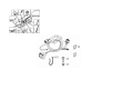
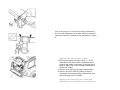
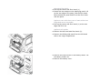
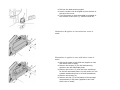
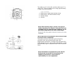
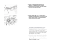
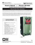
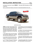
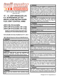
891: Cable harness kit for towbar, 7/4-pin
XC90, 2007, B8444S, TF-80SC AWD, L.H.D, YV4CZ852671372388, 372388
20/6/2014
PRINT
891: Cable harness kit for towbar, 7/4-pin
Cable harness kit for towbar, 7/4-pin
Installation instruction: 30756532
INTRODUCTION
Read through all of the instructions before starting
installation.
Notifications and warning texts are for your safety
and to minimise the risk of something breaking
during installation.
Ensure that all tools stated in the instructions are
available before starting installation.
Certain steps in the instructions are only
presented in the form of images. Explanatory text
is also given for more complicated steps.
In the event of any problems with the instructions
or the accessory, contact your local Volvo dealer.
Cars equipped with SRS/SIPS (Airbag)
Warning! Extra care must be taken when working
on cars equipped with SRS/SIPS air bags. This is
important to prevent: 1. Personal injury 2.
Damage to or malfunction of the SRS/SIPS
system. Work on the SRS/SIPS systems or related
components must always be carried out by an
authorised Volvo workshop.
Is the car equipped with SRS (supplemental
restraint system)?
Cars equipped with a driver's airbag have the letters
"SRS" imprinted on the centre panel of the steering
wheel. Cars equipped with driver's and passenger
airbags are marked with "SRS" on both the steering
wheel centre panel and also on the dashboard close to
the airbag.
If the car is equipped with SIPS (side impact protection
system ) a "SIPS" decal is marked on both the front
seats.
Cars equipped with inflatable curtains have the marking
"SRS" on one of the panels along the posts on the inside
of the car.
Cars equipped with SRS (supplemental restraint
system) also have an "SRS" decal on the front
windscreen.
Warning! The air bag inflation areas must not be
obstructed. Never place any objects, such as
upholstery or accessories, within these areas. The
panels must be able to open in the correct manner
at the right time, otherwise there is an increased
risk of personal injury in the event of a collision.
Do not damage the SRS wiring!
Do not trap, chafe, pierce or damage the SRS wiring.
SRS wiring has orange casing and/or is plaited.
Steering and front suspension
The contact reel in the SRS system can easily be
damaged when working on the steering wheel, steering
shaft or steering gear. Refer to the SRS (supplemental
restraint system) Service Manual or service instructions
in VIDA for information on carrying out such work. This
is to prevent damage.
SRS warning lamp
If the SRS warning lamp lights after repairs have been
carried out, take the car to an authorised Volvo
workshop.
Supplemental restraint system module, SRS
C30/S40(04-)/V50/S60/XC60/C70(06)/V70/XC70/S80/XC90
The supplemental restraint system module (SRS) is
located on the tunnel under the centre console, in front
of the parking brake.
Warning! The ignition must be in position "0" and
the key removed from the ignition switch if any
connector in the SRS system is to be unplugged.
Then wait at least three minutes and disconnect
the battery negative lead before unplugging any
of the connectors. When work is completed, the
ignition key must be turned to position "II" before
reconnecting the battery negative lead.
Cable harness kit for towbar, 7/4-pin
Illustration A
Install the trailer connector with the four screws
and the nuts. Tighten.
Pull the cable harness out towards the right along
the front edge of the tow bar member.
Secure the cable harness with a tie strap on the
sides of the tow bar member brackets.
Figure B applies to cars with R-design Skidplate
On cars with Skidplate, the contact shall be turned 90°
counter-clockwise in relation to the placement in Figure
A.
Applies to cars with two rows of seats
Fold up the centre rear floor hatch (1). If the
underside of the floor hatch is equipped with a
grocery bag holder, the holder is secured with a
strap on both ends of the storage compartment.
Detach the straps.
Remove the underlying storage compartment.
Remove the floor hatch by folding it almost
completely closed and pulling it backwards from
the mountings until it releases.
Applies to cars with three rows of seats and
integrated carrier bag holder on the underside of
the centre floor hatch
Fold up the centre rear floor hatch (1).
Detach the two straps on the underlying panel. Lift
up the rear edge of the panel, fold the floor hatch
back towards the panel and lift out the floor hatch
with the panel.
Applies to cars with three rows of seats without an
integrated carrier bag holder
Fold up the centre rear floor hatch (1) at the rear
edge and lift it out.
Applies to all models
Remove the left-hand side floor hatch (2).
Remove the folding side panel from the left-hand
side in the cargo compartment.
Remove the three screws in the battery holder. Lift
the battery holder out.
Remove the battery cover.
Pull off the rubber strip at the rear edge of the
door opening for the left-hand rear door opposite
the left-hand C-post panel.
Carefully pry off the left-hand C-post panel sides at
the top. Use a plastic weatherstrip tool. Then pull
until the three clips on the inside release. Do not
damage the headlining or the panel.
Remove the panel by pulling upwards slightly and
unhooking it from the side panel.
Remove the rear roof panel covers and the screws
beneath them.
Carefully pry off the panel at the rear edge. Use a
plastic weatherstrip tool.
Pull the rear edge of the panel downwards until the
four clips on the top release.
If the car is equipped with lighting in the panel,
unplug the connector from the panel.
Pull the panel backwards to release it.
Carefully pull off the D-post panel. Start at the top
edge then pull down until the three clips on the
inside release. Do not damage the panel.
Disconnect the connector on the D-post panel (if
the car has a loudspeaker in the D-post, the
connector is in the loudspeaker).
Remove the panel by pulling upwards slightly and
unhooking it from the side panel.
Illustration A shows the removal of the cover for
the load securing eyelets
Fold out the load securing eyelet.
Insert a scriber with an angled tip into the hole in
the top of the cover.
Turn the scriber so that the angled tip engages in
the reverse of the cover (1). Pull the cover off.
Illustration B applies to cars with two rows of
seats
Illustration C applies to cars with three rows of
seats
Fold up the seats in the third row (applies to cars
with three rows of seats).
Remove the screws (2) for the load securing
eyelets in the left-hand side panel.
Remove the covers (3) over the front mountings
for the left-hand side panel. Pry the covers off. Use
a plastic weatherstrip tool or a small screwdriver.
Remove the screws (4).
Remove the clip (5) at the bottom of the storage
compartment in the panel (Applies to cars with
three rows of seats).
Remove the panel by pulling out the upper edge
slightly so that the clips on the inside release. Pull
the panel straight up.
Remove the drain hose (1) from the battery.
Remove the rubber seal (2). It will not be re-used.
Pull off the small, thin rubber strap on the new
rubber seal.
Insert the old drain hose through the new rubber
seal. Make sure the hose is not obstructed and
that it is not folded.
Illustration A
Route the cable harness from the tow bar
connector through the hole in the floor.
Adjust the position of the rubber seal (1) so that
there is not excessive cable slack under the car.
Install the rubber seal in the hole.
Route the cable harness as illustrated. Insert it
through the hole along the rear edge of the lefthand cargo floor support.
Secure the cable harness to the cable harness
behind the battery with tie straps (2) from the kit.
Illustration B
Connect the routed ground cable to the grounding
point (3) behind the battery and tighten the
grounding screw securely.
Connect the drain hose (4) to the battery.
Make sure the cable harness curves around the
lower edge of the bumper as shown in the
illustration.
Note! If the cable harness is stretched too
tightly, it can scrape against the lower edge
of the bumper and become damaged.
Note! On the XC90 Executive, T-wiring is already
installed in the fuse holder. As this is a cable with
a black connector taped to it. The tow bar wiring's
black connector is then connected to this.
Detach the trailer module (TRM) from the Velcro
fastener on the floor along the rear edge of the
left-hand rear wheel housing.
Plug in the tow bar wiring connectors:
green (GN) and grey (GR) connectors to the
control module.
black (SB) connector to the fuse holder.
Reinstall the control module.
Secure the excess cable with a tie strap from the
kit.
Insert fuses from the kit in the following positions
in the fuse holder (REM):
20A in position 20 (mini fuse) if the charging
function will be used
25A in position 29
25A in position 30.
Reinstall:
the left-hand side panel using the screws and
cover. Tighten the screws in the load securing
eyelets. Tighten to 24 Nm (18 lbf ft) .
the covers for the load securing eyelets.
D-post panel with connector.
the connector for the rear roof lighting (if
applicable).
the rear headlining.
C-post panel.
protective cover and bracket for the battery.
side floor hatch and folding panel.
storage compartment and floor hatch.
Checking the trailer connector
1.
2.
3.
4.
5.
6.
7.
7-pin connection
Brake lamp / Left-hand indicator lamp
Ground
Spare (Brake lamp, Electric brakes)
Brake lamp / Right-hand indicator lamp
Charging
Position lamps
Spare (Reversing lamp)
The cable to pin 3 is blue (BL) and the cable to pin 7 is
violet (VO). They are taped to the wiring approximately
1 meter from the connector.
1.
2.
3.
4.
4-pin connection
Brake lamp / Right-hand indicator lamp
Brake lamp / Left-hand indicator lamp
Position lamps
Ground
Note! The following steps (16-25) only apply if
further functions are desired. These parts are not
included in the kit. Specified part numbers can be
purchased separately from Volvo dealerships.
Steps 16-23 only apply if electric brakes are to be
installed.
The image with wiring diagram shows the principle
of electric brake connection.
The system must be fused with quick-acting fuse,
maximum 30A, and controlled with relay, see
diagrammatic illustration. Use Maxi fuse (P/N 9441158),
quick-acting fuse max. 30A by ATO (P/N 966331) or Mini
(P/N 8470580) type. A separate holder must be used for
these.
Note! Installation of equipment for the electric
brakes must be carried out according to the
supplier's instructions. Volvo takes no
responsibility for such equipment.
Obtain positive feed (30+) from position 3 in the
main fuse box, which is located beside the battery.
Insert a 40A Midi fuse in the holder (P/N
9441937).
Connection of relay control to "Ignition on" in the
rear electronic module (REM)
Press in the catch on the front black connector in
the cargo compartment fuse holder. Turn up the
lock arm as far as possible and pull out the
connector.
Carefully prise apart the sides of the connector
holder in the ends so that the connector can pass
by the retaining hooks.
Pull the connector out from the holder.
Connect a replacement part terminal (P/N
30656727) to position 30 in the connector.
Reinstall the connector in the holder and reinstall
the whole unit in the fuse holder.
Connect ground lead (31-) to the relay with a
conductor with cable terminal (P/N 970784) to the
existing ground terminal (1) behind the battery.
Tighten the ground screw firmly.
Only applies if the brake lamp signal is to be
connected to the electric brakes
Connect a replacement part terminal (P/N
30656647) to position 1 in the tow hitch wiring's
gray connector on the trailer module (TRM).
Splice it with the cable for the brake lamp's input
signal from the brake equipment, with a yellow
butt connector (P/N 9130477).
Connect the electric brakes after the relay with a
fuse, maximum 30A. Connect the electric brake
output to the trailer connector via pin 3, spare
(see step 15).
The cables should have a minimum 4 mm² crosssection if a 30A fuse is used.
The equipment will be supplied with power as long
as the car has its ignition on.
Note! If the electric brakes are connected
without relay control in accordance with
above, then there is a risk that the car's
battery will be discharged.
Only applies if the brake lamp function is to be
used.
Connect a replacement part terminal (P/N
30656647) to position 1 in the tow hitch wiring's
gray connector on the trailer module (TRM).
Splice it with the blue (BL) cable that is taped to
the wiring, with a yellow butt connector (P/N
9130477).
The brake lamp signal is now in position 3 in the
trailer connector.
Only applies if the reverse lamp function is to be
used.
20/6/2014
Connect a replacement part terminal (P/N
30656724) to position H in the tow hitch wiring's
black connector on the fuse holder (REM). Splice it
with the violet (VO) cable that is taped to the
wiring, with a yellow butt connector (P/N
9130477).
The reverse lamp signal is now in position 7 in the
trailer connector.
PRINT