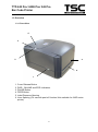
1
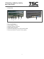
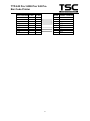
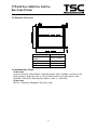
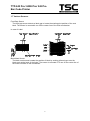
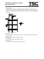
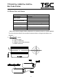
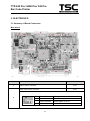
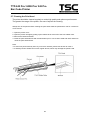
TTP 243 Pro/ 243E Pro/ 342 Pro THERMAL TRANSFER / DIRECT THERMAL BAR CODE PRINTER Service Manual TTP/TDP 244/342 TTP/TDP 244 TTP-243 Pro/ 243E Pro/ 342 Pro Bar Code Printer Table of Contents 1. FUNDAMENTALS ABOUT THE SYSTEM .................................................................. 1 1.1 Features of the TTP-243 Series ................................................................................. 1 1.2 Model Naming Syntax ................................................................................................. 1 1.3 Overview .................................................................................................................... 2 1.3.1 Front View........................................................................................................... 2 1.3.2 Rear View ........................................................................................................... 3 1.4 Basic Specifications.................................................................................................... 4 1.5 Effective Print Area ..................................................................................................... 6 1.6 Available Bar Codes ................................................................................................... 6 1.7 Various Sensors ......................................................................................................... 7 2. SUPPLY SPECIFICATIONS ............................................................................................. 9 2.1 Types of Paper ........................................................................................................... 9 2.2 Specifications ............................................................................................................. 9 2.3 Ribbon Sizes and Shapes ........................................................................................ 11 3. ELECTRONICS .............................................................................................................. 12 3.1 Summary of Board Connectors ................................................................................ 12 3.2 Pin Configuration ...................................................................................................... 14 4. MECHANISM .................................................................................................................. 16 4.1 Mainboard Replacement........................................................................................... 16 4.2 Cutter Installation (Option / Not available for TTP-243E Pro model) ......................... 20 4.3 Print Head Replacement .......................................................................................... 21 4.4 DC Motor Replacement ............................................................................................ 23 4.5 Ribbon Rewind Spindle Encoder Replacement ........................................................ 24 4.6 Felt Fabric Replacement .......................................................................................... 25 4.7 Stepping Motor Replacement ................................................................................... 27 4.8 Black Mark Sensor / Gap Sensor (Receiver) Replacement ...................................... 28 4.9 Ribbon Sensor (Receiver) Replacement................................................................... 29 4.10 Ribbon Sensor (Transmitter) / Gap Sensor (Transmitter) Replacement ................. 31 i TTP-243 Pro/ 243E Pro/ 342 Pro Bar Code Printer 4.11 Platen Replacement ............................................................................................... 32 5. TROUBLE SHOOTING ................................................................................................... 35 5.1 Trouble Shooting ...................................................................................................... 35 5.2 Calibrate the Gap Register ....................................................................................... 36 5.3 Self-test .................................................................................................................... 36 5.4 Ram Clear ................................................................................................................ 36 5.5 Diagnosis Operation Procedure ................................................................................ 36 5.6 Testing Sensors ....................................................................................................... 37 5.7 Cleaning the Print Head ........................................................................................... 38 ii TTP-243 Pro/ 243E Pro/ 342 Pro Bar Code Printer 1. FUNDAMENTALS ABOUT THE SYSTEM 1.1 Features of the TTP-243 Series 1. This bar code printer prints bar codes, characters, logos, on various types of labels and tickets by direct thermal or thermal transfer printing. 2 This printer adopts a “BASIC-like” high level programming language to help users programme the desired label forms with ease. 3. This bar code printer can be connected to a personal computer or an optional LCD keyboard to execute the programs downloaded in the printer’s memory. The printer is equipped with the following standard devices: black mark sensor, peel off module and real time clock. 4. This bar code printer provides a selection of optional features, including cutter module, memory module, portable LCD keyboard, etc. 5. The user friendly labeling software package is bundled with printer. 1.2 Model Naming Syntax T T P (1) – 2 4 3 (2) (3) (4) (1) Print method: TTP – Thermal Transfer Printing TDP – Thermal Direct Printing (2) Resolution of print head (DPI) (3) Maximum print width (Inch) (4) Maximum print speed (Inch/Sec) 1 TTP-243 Pro/ 243E Pro/ 342 Pro Bar Code Printer 1.3 Overview 1.3.1 Front View 4 3 2 5 6 1 1. 2. 3. 4. 5. 6. Cover Release Button PWR., ON-LINE and ERR. Indicators PAUSE Button FEED Button Label Dispense Opening Liner Opening (For use with peel-off function/ Not available for 243E series printer) 2 TTP-243 Pro/ 243E Pro/ 342 Pro Bar Code Printer 1.3.2 Rear View 1 2 3 5 4 6 1. Power On/Off Switch 2. Power Supply DC Jacket 3. RS-232C Interface Connector 4. USB Interface Connector 5. Label Insert Opening (For use with external media) 6. Centronics Interface Connector (Factory option) 3 TTP-243 Pro/ 243E Pro/ 342 Pro Bar Code Printer 1.4 Basic Specifications Thermal transfer and direct thermal printing High dot density printing (243 Pro series: 203 dots/inch, 342 Pro series: 300 dots/inch) Selectable print speeds at 1.5”, 2.0” or 3.0” per second (243 Pro series: 1.5, 2 and 3 ips / 342 Pro series: 1, 1.5 and 2 ips) Supports RS-232 serial and USB interface (Factory option for RS-232 and Centronics interface) Maximum media width up to 4.49” (114 mm) Adjustable label edge guide International character sets Print area:TTP-243 Pro/243E Pro:4.09” W x 90” L;TTP-342 Pro:4.09”W x 40”L (without any file downloaded in the printer memory) User selectable bar code ratios and heights Prints on labels or tickets Equipped with black mark sensor Equipped with Real Time Clock (Not available for TTP-243E Pro) Comes with self-peeling function (Not available for TTP-243E Pro) Buzzer provided to warn of possible errors (Not available for TTP-243E Pro) Label stock and thermal transfer ribbon are easy to install Internal label print counter Self test and hex dump mode Downloadable fonts from label design software Electronics/Communication Specifications Electrical DC Motor: DC24V Memory: ─SDRAM: 8 Mb ─Flash: 4 Mb Adapter 100~240VAC10%, 50~60Hz Regulations: FCC Class A, CE Class A, C-Tick Class A, TÜ V/Safety, CCC Communications Interface: Serial port: RS-232C (DB-9) at 2400, 4800, 9600 or 19200 baud rate ─Word Length: 7 or 8 data bits, 1 or 2 stop bits, selectable parity ─Handshaking: XON/XOFF and DSR/DTR Parallel port: Standard parallel interface Input Buffer: 64KB RS-232 Interface Pin Configuration: 4 TTP-243 Pro/ 243E Pro/ 342 Pro Bar Code Printer Host Function 9 Pin 25 Pin 9 Pin 1 RxD TxD DTR GND DSR RTS CTS 2 3 4 5 6 7 8 3 2 2 20 7 6 4 5 3 4 5 6 7 8 9 5 Printer Function +5V TxD RxD DSR GND RDY N/C RDY +5V TTP-243 Pro/ 243E Pro/ 342 Pro Bar Code Printer 1.5 Effective Print Area Label/Ticket Length Effective Print Length Label/Ticket Width Effective Print Width No Print Area 12mm~2286mm 10mm~2284mm 25mm~103mm 23mm~101mm 1mm 1.6 Available Bar Codes 1D bar code Code 39, Code 93, Code128UCC, Code128 subsets A.B.C, Codabar, Interleave 2 of 5, EAN-8, EAN-13, EAN-128, UPC-A, UPC-E, EAN and UPC 2(5) digits add-on, MSI, PLESSEY, POSTNET, RSS-Stacked, RSS14, Code 11, China Post 2D bar code PDF-417, Maxicode, DataMatrix, QR code, Aztec 6 TTP-243 Pro/ 243E Pro/ 342 Pro Bar Code Printer 1.7 Various Sensors Feed Gap Sensor The feed gap sensor detects a label gap to locate the starting print position of the next label. The sensor is mounted 4 mm off the center line of the main mechanism. . In case of Label Black Mark Sensor The black mark sensor locates the position of label by emitting infrared rays onto the black mark at the back of the ticket. The sensor is mounted 5.75 mm off the center line of the ticket roll width on the mechanism. 7 TTP-243 Pro/ 243E Pro/ 342 Pro Bar Code Printer In case of Ticket The default sensor position is (1) as shown on the figure below. To change to the (2) position, the customer should notify the manufacturer in advance. There can be only one position for the sensor. Once the sensor position is agreed upon, it can not be changed afterwards. Ribbon End Sensor The sensor detects the end portion of the ribbon. The ribbon end must be transparent. Label End Sensor The sensor detects the end portion of the label. Peel off Sensor The sensor detects the backing paper of a label. Ribbon encoder The encoder is used to detect if the ribbon is broken. 8 TTP-243 Pro/ 243E Pro/ 342 Pro Bar Code Printer 2. SUPPLY SPECIFICATIONS 2.1 Types of Paper Two types of media are available for TTP-243: label and ticket. In TTP-243, there are two types of sensors for paper: gap sensor and black mark sensor. Label and ticket can be further classified into direct thermal type or thermal transfer type. 2.2 Specifications Items Label Max.114mm Min. 25mm Length (Pitch) 12~2286mm Paper 0.20 mm Thickness Paper Weight Max 240 g/m2 Max. Roll Inner roll diameter. Max 4.3” (110mm) Diameter External roll diameter. Max 8.4” (1” core) (214mm) Roll Up Method Print surface wound outside as standard Paper Core ID. 25.7±0.3mm Paper Width Note: (1). The width and thickness quoted above are said of the label plus its backing paper. (2). Likewise, the approval of label entails that of its backing paper. (3). In the peel off mode, the minimum pitch is 35mm. (4). In the cutter mode, it is required the paper be wound outside. Otherwise, paper jam tends to result. (5). In the cutter mode, the paper thickness is 0.2 mm at maximum, and the paper weight is 2 100 g/m at maximum. (6). Paper shape is as shown on next page. (7) Tag is 0.2mm in thickness, and is less than 100g/m2 in weight. 9 TTP-243 Pro/ 243E Pro/ 342 Pro Bar Code Printer 10 TTP-243 Pro/ 243E Pro/ 342 Pro Bar Code Printer 2.3 Ribbon Sizes and Shapes Item Ribbon shape Ribbon width Ribbon winding width Leading tape End tape Max. ribbon OD. Winding method Specifications Spool type Max. 110mm Min. 40mm Max. 110mm Min. 40mm Polyester film, 3355mm long Polyester film (transparent), 2505mm long 67mm Ink surface to be wound outside Note: The maximum length of ribbon depends on its thickness and core outside diameter. The formula below defines the correlation between ribbon roll length and ribbon core diameter. L= (D 2 d 2 ) , where 4t L = Ribbon length D = Max. roll diameter d = Ribbon core outside diameter t = Ribbon thickness 11 TTP-243 Pro/ 243E Pro/ 342 Pro Bar Code Printer 3. ELECTRONICS 3.1 Summary of Board Connectors Main board 6 15 1 16 2 3 4 5 17 7 8 14 9 11 10 Connector 1 2 12 Description 13 Remark Ribbon sensor connector JP18 Black mark sensor connector JP46 Pin 1 2 3 Description Power Black mark sensor receiver GND 12 Voltage 5V No paper or black mark : 3.1~3.2V Detect paper: 0~0.3V 0V TTP-243 Pro/ 243E Pro/ 342 Pro Bar Code Printer Gap sensor connector 3 4 5 6 7 8 9 10 11 12 13 JP53 Pin 1 Description GND 2 Gap sensor emitter 3 4 Power GND 5 Gap sensor receiver 6 Power Voltage 0V Emitter on : 0.7~1.8V Emitter off: 2.4~2.7V 5V 0V No paper or gap: 3.1~3.2V Detect paper: 0~0.3V 5V Ribbon encoder sensor & DC motor connector Stepping motor connector Print head connector Micro processor Power switch Power supply output (24V DC) connector RS-232C connector Centronics port connector (Option) USB connector JP37 JP14 JP49 JP44 U2 SW2 B3 JP7 JP4 JP9 Push button connector JP52 SD memory card module connector Pin Description 1 LED green (PWR) 2 LED green (ONLINE) 3 LED red (ERR) 4 Pause switch 5 Feed switch 6 GND 14 Voltage LED light on: 2.0~2.2V LED light off: 0~0.3V LED light on: 2.0~2.2V LED light off: 0~0.3V LED light on : 2.0~2.2V LED light off: 0~0.3V 0V: Push key 3.3V: Stand-by 0V: Push key 3.3V: Stand-by 0V 15 Cutter /peel-off sensor connector (Option for TTP-243/342 Pro, not available for TTP-243E Pro) JP48 16 Head open sensor connector JP16 17 RTC Battery (Not available for TTP-243E Pro) BT1 13 TTP-243 Pro/ 243E Pro/ 342 Pro Bar Code Printer 3.2 Pin Configuration RS-232C PIN 1 2 3 4 5 6 7 8 9 CONFIGURATION +5 V TXD RXD CTS GND RTS N/C RTS N/C USB PIN 1 2 3 4 CONFIGURATION N/C DD+ GND Centronics Pin SPP Mode Nibble In/Out 1 Strobe N/A In 2-9 Data 0-7 N/A In 10 Ack N/A Out 11 Busy N/A Out N/A Out When low, device acknowledges reverse request. N/A N/A N/A N/A N/A N/A N/A Out GND N/A GND N/A GND N/A Extensibility flag N/A Out Paper Out / End 13 Select 14 Ground 15 No Defined 16-17 Ground 18 No Defined 19-30 Ground 31 No Defined 12 32 Error / Fault 14 Function A low on this line indicates that there are valid data at the host. When this pin is de-asserted, the +ve clock edge should be used to shift the data into the device. Data Bus. Single-directional. A low on this line indicates that there are valid data at the Device. When this pin is de-asserted, the +ve clock edge should be used to shift the data into the host. When in reverse direction, a high indicates data, while a low indicates a command cycle. In forward direction, it functions as PtrBusy. Ground Ground A low set by the device indicates that the reverse data is available TTP-243 Pro/ 243E Pro/ 342 Pro Bar Code Printer 33-35 36 Ground No Defined N/A N/A GND N/A 15 Ground TTP-243 Pro/ 243E Pro/ 342 Pro Bar Code Printer 4. MECHANISM 4.1 Mainboard Replacement 1. Turn off the printer power. 2. Remove the power cord and RS-232 and/or USB cable. 3. Open the top cover of the printer. 4. Remove the printer front panel. Remove the front cover in the direction of the arrows 5. Remove the two screws and the metal cover. Screws Metal Cover Remove the screws and metal cover 16 TTP-243 Pro/ 243E Pro/ 342 Pro Bar Code Printer 6. Release the cable tie and remove the peel-off sensor connector. (Not available for TTP-243E Pro model) Peel-Off Sensor Connector Cable Tie Cutter Connector Cable tie and peel-off sensor connector 7. Remove the screws on the lower left and lower right corners of main mechanism. Remove the screws in the lower left, lower right corners of the main mechanism. 17 TTP-243 Pro/ 243E Pro/ 342 Pro Bar Code Printer 8. Remove the four screws of the internal label roll mount. Fig. 3.18 Remove screws of the label roll mount 9. Move the mechanism about 5 mm in the label feed direction. 10. Take out the internal label roll mount and remove the connector. Push Button Connector Ground Wire Take out the internal label roll mount and remove the connector 18 TTP-243 Pro/ 243E Pro/ 342 Pro Bar Code Printer 11. Remove the screw of ground wire on the mainboard. 12. Remove all connectors on the mainboard. 13. Take out the mechanism. 14. Remove the rest three screws on the mainboard. Upper-Left, Upper-Right, Lower-Right Corner Screw 15. Replace the mainboard. 16. Reassemble the mechanism and internal label roll mount in the reverse procedures of the removal. 19 TTP-243 Pro/ 243E Pro/ 342 Pro Bar Code Printer 4.2 Cutter Installation (Option / Not available for TTP-243E Pro model) 1. Turn off the printer power. 2. Open the top cover of the printer. 3. Remove the printer front panel slowly and carefully. (Cf. 4.1 section) 4. Remove the two screws and the metal cover. (Cf. 4.1 section) 5. Release the cable tie and remove the peel-off sensor connector. (Cf. 4.1 section) 6. Remove the peel-off sensor connector. 7. Plug in the cutter connector. 8. Insert the right and left side flange of cutter into the slot. Right Flange Left Flange Cutter Installation 9. Fasten the cutter from the bottom of the printer with the provided screw. 10. Make sure no screws or other parts are left in the printer. 11. Reassemble the mechanism and internal label roll mount in the reverse procedures of the removal. 20 TTP-243 Pro/ 243E Pro/ 342 Pro Bar Code Printer 4.3 Print Head Replacement 1. Turn off the printer power. 2. Remove the RS-232 cable and power cord. 3. Open the top cover. 4. Remove the ribbon and label roll. 5. Open the print carriage. 6. Remove the screw at the top front center of the mechanism, as shown. The Print Head Screw 7. Disconnect the print head cable. Print Head Cable Key of the Connector Print Head Connector Printhead and the Cable 21 TTP-243 Pro/ 243E Pro/ 342 Pro Bar Code Printer Note: The key of connector must be positioned upward. Do not touch the elements of the print head. Do not disassemble the print head. 8. Tidy up the cable so that it does not protrude or interfere with the ribbon. 9. Reassemble the removed parts in the reverse order of removal. 22 TTP-243 Pro/ 243E Pro/ 342 Pro Bar Code Printer 4.4 DC Motor Replacement 1. Turn off the printer power. 2. Remove the power cord and RS-232 and/or parallel port cable. 3. Open the top cover of the printer. 4. Remove the printer front panel. (Cf. 4.1 section) 5. Remove the two screws and the metal cover. (Cf. 4.1 section) 6. Release the cable tie and remove the peel-off sensor connector. (Cf. 4.1 section) 7. Remove the screw on the PCB of peel-off and cutter connector. 8. Remove the screws in the lower left, lower right corners of the main mechanism. (Cf. 4.1 section) 9. Remove all four screws of the internal label roll mount. (Cf. 4.1 section) 10. Move the mechanism in the label feed direction about 5 mm. 11. Take out the internal label roll mount and remove connector JP52. (Cf. 4.1 section) 12. Remove the screw of ground wire on the mainboard. 13. Remove all connectors on the mainboard. 14. Take out the mechanism. 15. Remove the cable tie. 16. Remove the three screws on DC motor fixture. DC Motor Fixture DC Motor Fixture 17. Remove the two screws used to fix DC motor on the fixture. 18. Replace the DC motor and pull out the cables in connector JP37. Note: The colors of DC motor wires in connector JP37 are yellow (outside) and green (inside). 19. Reassemble the removed parts in the reverse order of the removal. 23 TTP-243 Pro/ 243E Pro/ 342 Pro Bar Code Printer 4.5 Ribbon Rewind Spindle Encoder Replacement The encoder is installed on the gear box of DC motor, and is used to detect if the ribbon is unerringly rewound by the spindle. The encoder is connected to JP37 on the mainboard. Please switch the printer to thermal transfer mode. The multi-meter is used to measure the voltage of Pin2 (+5V). If the voltage changes continuously from 0 to 5 volts DC, the encoder is in condition. Otherwise, please follow the steps below to replace the encoder PCB 1. Follow directions in Section 4.4 to remove DC motor and DC motor fixture. DC Motor Encoder 2. Remove the two flat tap screws and cable tie. 3. Replace the Encoder PCB. 4. Reassemble the removed parts in the reverse order of removal. 24 TTP-243 Pro/ 243E Pro/ 342 Pro Bar Code Printer 4.6 Felt Fabric Replacement Felt Fabric is located in the ribbon supply spindle. It is used to tighten the ribbon to prevent it from getting wrinkled during printing. If the ribbon can not be tightened when label back feeds during printing, please replace with a new felt to secure the best printing quality. Follow the steps below to replace the felt fabric. 1. Follow the instructions in Section 4.4 to remove DC motor and DC motor fixture. 2. Remove the E-ring and washer on ribbon supply spindle. Spring Holder E Ring Spring Washer Spring Cover Felt Clutch Compression Spring Felt Fabric Components of the Ribbon Supply Spindle 3. Remove the spring cover, compression spring and spring holder. 4. Remove the spring, felt clutch and felt fabric. 5. Replace with a new felt. Side View of the Ribbon Supply Spindle Assembly 25 TTP-243 Pro/ 243E Pro/ 342 Pro Bar Code Printer 6. Reassemble the removed parts in the reverse order of removal. Front View of the Ribbon Supply Spindle 26 TTP-243 Pro/ 243E Pro/ 342 Pro Bar Code Printer 4.7 Stepping Motor Replacement 1. Follow the instructions in Section 4.1 to remove all the connectors on mainboard. 2. Take out the mechanism. 3. Remove the two screws of the stepping motor. Stepping Motor 4. Replace the stepping motor and reassemble the removed parts in the reverse order of removal. 27 TTP-243 Pro/ 243E Pro/ 342 Pro Bar Code Printer 4.8 Black Mark Sensor / Gap Sensor (Receiver) Replacement Black mark sensor is reflection type sensor. It is connected to JP46 (3 pin connector). A multi-meter is used to measure the signal of Pin2 to see if there is voltage variation when black mark is detected. Before conducting the test, please issue the BLINE command first. The printer will switch from gap sensor to black mark sensor. If there is no voltage variation, please follow steps below to replace the black mark sensor / gap sensor (receiver) PCB. 1. Follow the instructions in Section 4.1 to remove all the connectors on mainboard. 2. Take out the mechanism. 3. Remove one flat tap screws and black mark sensor PCB. Black Mark Sensor and Gap Receiver Sensor 4.Reassemble the removed parts in the reverse order of removal. 28 TTP-243 Pro/ 243E Pro/ 342 Pro Bar Code Printer 4.9 Ribbon Sensor (Receiver) Replacement 1. Follow the instructions in Section 4.1 to remove all the connectors on mainboard. 2. Take out the mechanism. 3. Remove the screws, springs and spring bushing on both sides of the mechanism. Spring Installation on Left Side and Right Side Note: The left side spring and the right side spring are different in shape. The right side spring has a straight end, when the left side spring has an end that is curved 90 degrees. 4. The main mechanism is divided into upper mechanism and lower mechanism. 5. The ribbon sensor (receiver) is located in the upper mechanism. 6. Remove the screws on the ribbon sensor cover. Print Head Sensor Cover Flat Tap Screw Ribbon Sensor Cover 29 TTP-243 Pro/ 243E Pro/ 342 Pro Bar Code Printer 7. Replace with a new ribbon sensor PCB. Ribbon Sensor 8. Reassemble the removed parts in the reverse order of removal. 30 TTP-243 Pro/ 243E Pro/ 342 Pro Bar Code Printer 4.10 Ribbon Sensor (Transmitter) / Gap Sensor (Transmitter) Replacement 1. Follow the instructions in Section 4.1 to remove all the connectors on mainboard. 2. The ribbon sensor (transmitter) is located in the center of the lower mechanism. Ribbon Sensor (Transmitter) 3. Remove the two flat tap screws. 4. Remove the cable tie and sensor PCB. 5. Replace with a new PCB. Reassemble the removed parts in the reverse order of removal. 31 TTP-243 Pro/ 243E Pro/ 342 Pro Bar Code Printer 4.11 Platen Replacement 1. Follow the instructions in Section 4.7 to remove the two screws, stepping motor and stepping motor cover. 2. Remove the E ring and two gears. Thermal Head Printer Carriage Release lever arm Gear #1 E Ring Gear #2 Location of E ring and Gears 3. Remove the E-ring and the printer carriage release lever on the left side of the mechanism. 4. Remove the E-ring and the printer carriage release lever arm. Bracket Thermal Head Printer Carriage Release Lever E Ring Printer carriage release lever and E ring 32 TTP-243 Pro/ 243E Pro/ 342 Pro Bar Code Printer Stripper Bar Platen Bush (Right Side) Printer Carriage Release Lever Arm Teflon Tube E Ring Printer carriage release lever arm and E ring 5. Remove the teflon tube and stripper rod. Teflon Tube Teflon tube and stripper rod 6. Remove the E ring, the right side and left side platen bushes. 7. Remove the stripper bar. Platen Bush (Left Side) E Ring Remove E ring and platen bush 33 TTP-243 Pro/ 243E Pro/ 342 Pro Bar Code Printer 8. Move the platen to the right of the mechanism. 9. Replace the platen and reassemble the removed parts in the reverse order of removal. 34 TTP-243 Pro/ 243E Pro/ 342 Pro Bar Code Printer 5. TROUBLE SHOOTING 5.1 Trouble Shooting Problems Solutions 1. Ribbon does not advance. Check the printing mode setting and reset the printer. 2. Poor print quality. Clean the print head. Adjust the print density setting. 3. Only prints diagonal pattern in the self-test. Ribbon and paper are incompatible. Use a different type of ribbon. 4. Power indicator light does not illuminate. Check the connection of serial port cable. 5. On-line indicator light does not to illuminate. Check the DIP switch setting and reset the printer. Check that power cord is properly connected. 6. Error indicator remains illuminated. Out of paper or out of ribbon. Check the DIP switch setting Check the paper core, make sure it is installed on the ribbon rewind spindle. Press the FEED key. The error message will be printed out on the print media or sent out through RS-232 port. If there is no problem with direct thermal printing, but error occurs in thermal transfer printing. Please check the encoder of the DC motor. 35 TTP-243 Pro/ 243E Pro/ 342 Pro Bar Code Printer 5.2 Calibrate the Gap Register Install the label. Turn on the printer power while pressing the PAUSE button. The printer will calibrate the transparency of the backing paper and adjust the gap register. 5.3 Self-test Install the label. Turn on the printer power while pressing the FEED button, the printer will: Print head checking pattern. Calibrate the label length. Print internal settings. Initiate self-test. Enter dump mode. 5.4 Ram Clear Press the PAUSE and FEED button simultaneously for more than 3 seconds. The printer will clear the memory and reset the printer. Be sure to calibrate the gap register with blank label before printing. 5.5 Diagnosis Operation Procedure When the power is turned on without any button pressed, self diagnosis is performed automatically to test the available memory. If any error occurs during this period, the ERR light will flash. Do the self test and inspect the test pattern to check if the thermal head is available. 36 TTP-243 Pro/ 243E Pro/ 342 Pro Bar Code Printer 5.6 Testing Sensors A. Checking Ribbon Sensor Switch the multimeter to the DC gear. Connect the black wire to DC GND, and the red wire to PIN2 of JP18. 1. When ribbon is detected between TX and RX of the ribbon sensor, the measured voltage should be 5 Vdc. 2. When ribbon is not detected between TX and RX of the ribbon sensor, the measured voltage should be 0 Vdc. The ribbon sensor is normal if the checking complies with the two cases above. Or else, the ribbon sensor is out of order. B. Checking DC Motor Encoder Sensor Switch the multimeter to the DC gear. Connect the black wire to DC GND, and the red wire to PIN4 of U35. 1. When gap of the gear box is detected by the DC motor encoder sensor, the measured voltage should be 5 Vdc. 2. When gap of the gear box is not detected by the DC motor encoder sensor, the measured voltage should be 0 Vdc. The DC motor encoder sensor is normal if the checking complies with the two cases above. Or else, the DC motor encoder sensor is out of order. C. Checking Black Line Sensor Switch the multimeter to the DC gear. Connect the black wire to DC GND, and the red wire to PIN2 of U2. Load black line label on the printer. 1. When black line is detected by the black line sensor, the measured voltage should be 3 Vdc. 2. When black line is not detected by the black line sensor, the measured voltage should be 0 Vdc. The black line sensor is normal if the checking complies with the two cases above. Or else, the black line sensor is out of order. 37 TTP-243 Pro/ 243E Pro/ 342 Pro Bar Code Printer 5.7 Cleaning the Print Head The printer should be cleaned regularly to retain high quality and optimum performance. The greater the usage of the printer, the more frequent the cleaning. Always turn off the printer before cleaning the print head. Allow the printhead to cool for a minimum of one minute. 1. Open the printer cover. 2. Open the printer carriage by pulling up the release lever to the left of the front rubber roller. 3. Remove the ribbon and label. 4. Clean the print head element with a head cleaner pen or use a cotton swab and 100% ethanol to clean the print head surface. Note: * Do not touch printer head by hand. If you touch it careless, please use ethanol to clean it. * It’s industry alcohol. Please do not use regular alcohol, which may damage the printer head. 38 TTP-243 Pro/ 243E Pro/ 342 Pro Bar Code Printer Update History Date 2011/1/25 2011/4/7 Content Modify TSC address Modify section 3.2 Editor Camille Camille 39 TSC Auto ID Technology Co., Ltd. Corporate Headquarters 9F., No.95, Minquan Rd., Xindian Dist., New Taipei City 23141, Taiwan (R.O.C.) TEL: +886-2-2218-6789 FAX: +886-2-2218-5678 Web site: www.tscprinters.com E-mail: [email protected] [email protected] Li Ze Plant No.35, Sec. 2, Ligong 1st Rd., Wujie Township, Yilan County 26841, Taiwan (R.O.C.) TEL: +886-3-990-6677 FAX: +886-3-990-5577