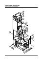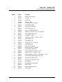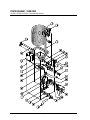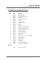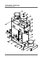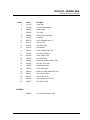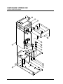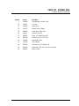
1
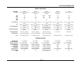
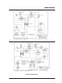
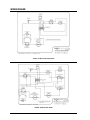
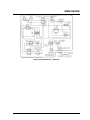
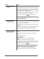
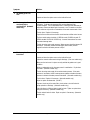
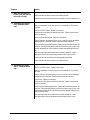
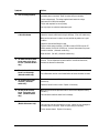
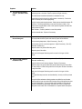
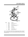
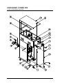
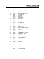
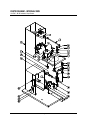
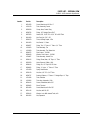
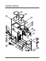
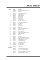
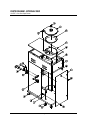
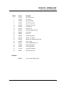
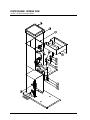
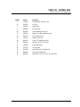
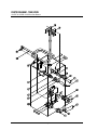
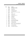
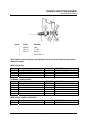
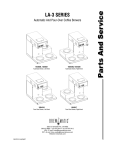
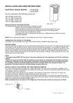
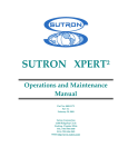
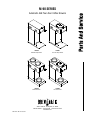
M-90 SERIES
Automatic And Pour-Over Coffee Brewers
1010546
Automatic Airpot Brewer
1010547
Pour-Over Airpot Brewer
1010559
Automatic Brewer
1010548
Pour-Over Brewer
3828 S. Main St. Los Angeles, CA 90037
800-421-6860 • 310-787-5444 • Fax 310-787-5412
brewmatic.com
FM CS107 Rev B 10/14/04
TABLE OF CONTENTS
Important Information
Page 3
Appliance Information
Page 4
Pages 5 – 7
Wiring Diagrams
1010546 - M-90 Automatic Airpot Brewer
1010559 – M-90 Automatic Brewer
1010547 – M-90 Pour-Over Airpot Brewer
1010548 – M-90 Pour-Over Brewer
1010544 – M-90 Automatic Brewer, 120/240 Volts
Troubleshooting Guide
Pages 8 - 14
Pages 15 – 36
Parts Diagrams And Parts Lists
6003093 - Element Pan Assembly W/PTC Black
1010546 - M-90 Automatic Airpot Brewer
1010559 & 1010544 – M-90 Automatic Brewer
Tank Assembly – M-90 Automatic Brewers
1010547 – M-90 Pour-Over Airpot Brewer
1010548 – M-90 Pour-Over Brewer
Tank Assembly – M-90 Pour-Over Brewers
Previous Tank Fitting Revisions
Page 2
IMPORTANT INFORMATION
Read all instructions and safeguards included in the original packaging, and this service manual, carefully
and completely before installing, operating or servicing this appliance. Additional copies of installation
instructions and service manuals are available upon request.
The proper performance of service is essential for the safe and effective operation of this appliance. Repairs
should be performed by qualified service personnel only. If you are unable to, or need help servicing this
appliance, contact the nearest Brewmatic Authorized Service Agent or you can contact Brewmatic at 800421-6860.
Only Authorized Replacement Parts Should Be Used. Part substitutions could create a fire hazard and the
risk of personal injury. The use of replacement parts or accessory attachments not recommended by
Brewmatic may be hazardous.
Do Not By-Pass Any Safety Mechanisms Or Operate This Appliance Without Covers In Place. Brewmatic
requires that all safety devices and covers be in place and functioning at all times to guard against a fire
hazard and the risk of personal injury.
Brewmatic Does Not Recommend, And Will Not Furnish Anyone With Information For Changing The
Electrical Rating Of Any Appliance Manufactured Or Distributed By Brewmatic. Brewmatic will not
approve of any unauthorized changes to the basic design of this appliance. Any modification or alteration to
the appliance may create a fire hazard, may create a risk of personal injury, may void the safety listings and
may void the warranty.
Plumbing connections - All plumbing connections to water supply lines and drains should be performed by a
licensed plumber complying with all applicable plumbing codes having jurisdiction.
Electrical connections - With the exception of cords with plugs already attached, all electrical connections or
alterations to the power supply should be performed by a licensed electrician complying with all applicable
electrical codes having jurisdiction.
When repairing or replacing internal electrical wiring, in part or in whole, use only terminals and wires with
the same rating, gauge and insulation covering.
When calling for information, parts or service, have the model number, serial number, voltage, phase and
date of purchase available. Electrical information may be obtained from the electrical information nameplate
located on the appliance.
All procedures, diagrams and specifications contained in this manual are based on the latest information
available at the time of publication. Information, parts and specifications are subject to change without
notice.
We assume no liability for any damage to person or property caused by the utilization of this publication to
effect maintenance or repairs.
Due to periodic reviews and changes in safety listing standards, listings and approvals may change at any
time. For current listing and approval information contact Brewmatic.
Page 3
APPLIANCE INFORMATION
Appliance Specifications:
Model Number:
Description:
Volts:
Watts:
Amps:
Hertz:
Phase:
Power Supply Cord:
Plug:
Power Supply Required:
Wall Receptacle Required:
Water Supply Required:
Water Connection:
Listings:
1010546
M-90 Automatic Airpot Brewer
With Faucet
1010559
M-90 Automatic Brewer
With Faucet
120
1510
12.5
60
1
120
1780
14.8
60
1
6 Ft., 2 wire + ground, 15 Amp,
14 awg.
NEMA 5-15 P. Furnished and
attached.
120 volt, 15 amp, dedicated
circuit.
15 Amp. NEMA 5-15 R. Not
furnished.
1010544
M-90 Automatic Brewer
With Faucet
1010547
M-90 Pour-Over
Airpot Brewer
1010548
M-90 Pour-Over Brewer
60
1
120
1500
12.5
60
1
120
1680
14.0
60
1
6 Ft., 2 wire + ground, 15 Amp,
14 awg.
NEMA 5-15 P. Furnished and
attached.
120 volt, 15 amp, dedicated
circuit.
15 Amp. NEMA 5-15 R. Not
furnished.
6 Ft., 3 wire + ground, 20 Amp,
14 awg.
NEMA L14-20 P. Furnished and
attached.
120/240 or 120/208 volt, 20
amp, dedicated circuit.
20 Amp. NEMA L14-20R. Not
furnished.
6 Ft., 2 wire + ground, 15 Amp,
14 awg.
NEMA 5-15 P. Furnished and
attached.
120 volt, 15 amp, dedicated
circuit.
15 Amp. NEMA 5-15 R. Not
furnished.
6 Ft., 2 wire + ground, 15 Amp,
14 awg.
NEMA 5-15 P. Furnished and
attached.
120 volt, 15 amp, dedicated
circuit.
15 Amp. NEMA 5-15 R. Not
furnished.
30 psi min., 80 psi max.
1/4" Flare. Flared nut supplied.
30 psi min., 80 psi max.
1/4" Flare. Flared nut supplied.
30 psi min., 80 psi max.
1/4" Flare. Flared nut supplied.
None required.
None required.
UL, NSF, MEA & LA Mech.
UL, NSF, MEA & LA Mech.
UL, NSF, MEA & LA Mech.
UL, NSF, MEA & LA Mech.
UL, NSF, MEA & LA Mech.
120/240
3600
15.0
120/208
3000
14.5
Additional Information:
Brewing Capacity:
Brewing Temperature:
Temperature Adjustment:
Beverage Adjustment:
Timer Setting:
Faucet Adjustment:
Flow Control:
Hi-Limit Thermostat:
Receptacle Supplied
On Unit
74 oz. maximum.
192° - 196°F
3 Increase. 4 Decrease
3 Increase. 4 Decrease
2:10 Min., Approximately
4 Increase. 3 Decrease
.19 gpm. Not Adjustable.
Manual. Not adjustable.
None.
64 oz. maximum.
192° - 196°F
3 Increase. 4 Decrease
3 Increase. 4 Decrease
1:50 Min., Approximately.
4 Increase. 3 Decrease
.25 gpm. Not Adjustable.
Manual. Not adjustable.
None.
64 oz. maximum.
192° - 196°F
3 Increase. 4 Decrease
3 Increase. 4 Decrease
1:50 Min., Approximately.
4 Increase. 3 Decrease
.25 gpm. Not Adjustable.
Manual. Not adjustable.
NEMA 5-15R, 120v, Switched.
600w maximum.
Page 4
64 oz. maximum.
192° - 196°F
3 Increase. 4 Decrease
None
None
None
None
Manual. Not adjustable.
None.
64 oz. maximum.
192° - 196°F
3 Increase. 4 Decrease
None
None
None
None
Manual. Not adjustable.
None.
WIRING DIAGRAM
1010546 - M-90 Automatic Airpot Brewer
1010559 - M-90 Automatic Brewer
Page 5
WIRING DIAGRAM
1010547 - M-90 Pour-Over Airpot Brewer
1010548 - M-90 Pour-Over Brewer
Page 6
WIRING DIAGRAM
1010544 - M-90 Automatic Brewer, 120/240 Volts
Page 7
TROUBLESHOOTING
Read and follow the cautions below before attempting to service this coffee brewer.
CAUTION:
Read and verify that the installation instructions have been followed before attempting to operate this
appliance. Incorrect installation or operating procedures will void the warranty and may damage this
appliance.
Unplug the power cord before servicing, unless electrical testing is required. Be certain the power supply
is of the correct rating and polarity before connecting the power supply cord. The chassis must be grounded
to prevent possible electric shock. Failure to heed this warning may damage this appliance and may cause
injury.
Under no circumstance should the hi-limit thermostat be by-passed. In the event of failure the hi-limit
thermostat should be replaced. Use only original or authorized replacement parts.
Carefully inspect the internal wiring for wear or damage when servicing. Worn or damaged wiring may
cause malfunctions and premature component failures. Replace any wires that have loose connections,
damaged insulation or show evidence of overheating. When repairing or replacing internal electrical wiring,
in part or in whole, use only terminals and wires with the same rating, gauge and insulation covering.
Adjusting the faucet flow beyond factory recommended settings could result in rapid cooling of the faucet
flow or result in excessive faucet head pressure.
Symptoms
Solutions
1. The coffee brewer will not
operate. The lights and
warmers do not work, and
the coffee brewer will not
brew coffee.
Make sure the power supply cord is connected to a proper, working wall
receptacle.
Make sure the "On-Off-Fill" switch has been turned on. (Pour-over models have
an "On-Off" switch.)
Check the main circuit breaker in the building to see if it has tripped.
Reset or replace the hi-limit thermostat. (120v models only.)
Check to make sure the internal wiring is correct. Inspect for loose, damaged or
overheating wires or terminals. Repair or replace wiring as necessary.
Test the "On-Off-Fill" switch. Replace it if necessary. (Pour-over models have an
"On-Off" switch only.)
Test the power supply cord. Replace it if necessary.
Page 8
Symptoms
2.
The coffee brewer will not
brew coffee. The lights and
warmers work, and the
coffee brewer heats.
Solutions
Test the start switch. Replace it if necessary. (Automatic models only.)
Water or condensation on the timer may cause it to malfunction. Dry the timer
and retest. (Automatic models only.)
On pour-over models, water must be poured in to initiate a brew cycle. Pour in
approximately 64 oz. of water for each brew cycle. See installation instructions
for correct procedures. (Pour-over models only.)
Inspect the reservoir and reservoir tubing for blockage. (Pour-over models only.)
Check to make sure the internal wiring is correct. Inspect for loose, damaged or
overheating wires or terminals. Repair or replace wiring as necessary.
Test the timer. Replace it if necessary. (Automatic models only.)
Open the flow control and clean the flow control washer and flow control screen.
(Automatic models only.)
Test the "On-Off-Fill" switch. Replace it if necessary. (Automatic models only.)
Test the solenoid valve. Replace it if necessary. (Automatic models only.)
If present, check any in-line water filters, check valves or shut-off valves for
proper operation or blockage. (Automatic models only.)
3.
The coffee brewer will not
heat. The lights and
warmers work. The water
for brewing is cold.
Reset or replace the hi-limit thermostat. (120/240v models only).
Test the thermostat. Replace it if necessary.
Test the immersion element. Replace it if necessary.
Check to make sure the internal wiring is correct. Inspect for loose, damaged or
overheating wires or terminals. Repair or replace wiring as necessary.
Test the power relay. Replace it if necessary. (120/240v models only.)
4.
The coffee brewer takes
much longer than normal to
heat. The lights and
warmers work.
Test the thermostat. Replace it if necessary.
Test the voltage supply. The voltage supplied should match the voltage
requirement on the electrical nameplate.
Test the immersion element. Replace it if necessary.
Check to make sure the internal wiring is correct. Inspect for loose, damaged or
overheating wires or terminals. Repair or replace wiring as necessary.
Test the power relay. Replace it if necessary. (120/240v models only.)
Page 9
Symptoms
5.
The hi-limit thermostat keeps
activating.
Solutions
Test the hi-limit thermostat. Replace it if necessary.
Test the brewing temperature. Adjust the thermostat if necessary. (See #7).
Check the hi-limit thermostat mounting clip. When placed in the mounting clip,
the hi-limit should be just snug against the tank. Too much pressure against the
tank could cause the hi-limit to activate prematurely.
Inspect the wiring on the hi-limit thermostat for loose, damaged or overheating
wires or terminals. Repair or replace wiring as necessary.
Test the power relay. Replace it if necessary. (120/240v models only.)
WARNING
Under no circumstance should the hi-limit thermostat be by-passed. In the
event of failure, the hi-limit thermostat should be replaced. Use only original
or authorized replacement parts.
6.
The coffee brewer trips the
buildings circuit breaker.
Too many appliances are connected on one electrical circuit.
The electrical circuits amperage rating is too low. Locate a correctly rated circuit
or call an electrician to correct this problem.
This coffee brewer may require a dedicated wall circuit. Check the electrical
specifications.
Check to make sure the internal wiring is correct. Inspect for loose, damaged or
overheating wires or terminals. Repair or replace wiring as necessary.
Inspect the immersion element for damage. Replace it if necessary.
7.
The brewing temperature is
either too hot or too cold.
The thermostat bulb must be in its clip and attached to the immersion element
correctly.
Inspect the thermostat bulb for excessive lime buildup. Clean the bulb if
necessary.
Adjust or replace the thermostat.
Thermostat Adjustment:
9920434: Clockwise to increase, Counter-clockwise to decrease.
9920450: Counter-Clockwise to increase, clockwise to decrease.
Turn the adjustment screw a maximum of 1/8 turn per adjustment. Retest and
adjust again if necessary. The recommended temperature is between 192° and
196°F. Test below brew cone with water only.
WARNING:
If the thermostat cannot be adjusted properly it should be replaced. The
thermostat is calibrated at the factory and no attempt should be made to
recalibrate it. Use only original or authorized replacement parts.
Test the power relay. Replace it if necessary. (120/240v models only.)
Page 10
Symptoms
8.
The brewing cycle is too
slow.
Solutions
Inspect and clean the spray head, silicone tubing and siphon fittings.
Inspect and clean the siphon screen on the inside of the tank.
9.
The beverage level is
consistently high or
consistently low. (Automatic
models only.)
Adjust the timer. To increase the beverage level, turn the timer adjustment knob
clockwise. To decrease the beverage level, turn the adjustment knob
counterclockwise. Turn the adjustment knob 1/2 reference mark maximum per
adjustment. Retest and adjust again if necessary. Note: The marks on the timer
are for reference only and are not intended as an accurate measurement of time.
Test the timer. Replace it if necessary.
Open the flow control and clean the flow control washer and flow control screen.
The flow control washer should be .19 GPM for model 1010546 only and .25
GPM for models 1010544 & 1010559 only. Incorrect flow washers can cause
inaccurate beverage levels.
Test the incoming water supply pressure. Water pressure should be between 30
and 80 psi. If the water pressure exceeds 80psi, install a water pressure
regulator and reduce the water pressure to 50psi.
10. The beverage level is
Inspect and clean the spray head, silicone tubing and siphon fittings.
inconsistent.
Inspect and clean the siphon screen on the inside of the tank.
Inspect the reservoir and reservoir tubing for blockage. (Pour-over models only.)
Make sure the tank cover is in place correctly and that the gaskets are in good
condition.
Water or condensation on the timer may cause it to malfunction. Dry the timer
and retest. (Automatic models only.)
Test the incoming water supply for inconsistent water pressure. If the water
pressure is inconsistent, install a water pressure regulator and reduce the water
pressure to minimize the water pressure fluctuations. (Automatic models only.)
Test the timer. Replace it if necessary. (Automatic models only.)
Adjust or replace the thermostat. (See #7.)
If present, check any in-line water filters, check valves or shut-off valves for
proper operation or blockage. (Automatic models only.)
Check the faucet coil fittings inside the tank for leaks. Tighten or replace these
fittings as necessary. (Automatic models only.)
Test the solenoid valve for leaks. Repair or replace it if necessary. (Automatic
models only.)
Page 11
Symptoms
Solutions
11. Water drips from the spray
Inspect and clean the spray head, silicone tubing and siphon fittings.
head for a long time after the
brew cycle is finished.
12. The brewing cycle starts by
itself. (Automatic models
only.)
Inspect and clean the siphon screen on the inside of the tank.
Inspect the reservoir and reservoir tubing for blockage. (Pour-over models only.)
Test the start switch. Replace it if necessary.
Water or condensation on the timer may cause it to malfunction. Dry the timer
and retest.
Test the "On-Off-Fill" switch. Replace it if necessary.
Check the faucet coil fittings inside the tank for leaks. Tighten or replace these
fittings as necessary.
Test the solenoid valve for leaks. Replace it if necessary.
Check to make sure the internal wiring is correct. Inspect for loose, damaged or
overheating wires or terminals. Repair or replace wiring as necessary.
Test the incoming water supply pressure. Water pressure should be between 30
and 80 psi. Excessive water pressure can cause the valve to open or leak. If the
pressure exceeds 80 psi, install a pressure regulator and reduce pressure to 50
psi.
Water flow should enter the solenoid valve on the side marked "IN". Water
entering the valve on the wrong side may cause the valve to open or leak.
Inspect and clean the spray head, silicone tubing and siphon fittings.
Inspect and clean the siphon screen on the inside of the tank.
13. The brewing cycle will not
shut off. (Automatic models
only.)
Test the start switch. Replace it if necessary.
Test the "On-Off-Fill" switch. Replace it if necessary.
Water or condensation on the timer may cause it to malfunction. Dry the timer
and retest.
Check to make sure the internal wiring is correct. Inspect for loose, damaged or
overheating wires or terminals. Repair or replace wiring as necessary.
Test the timer. Replace it if necessary.
Check the faucet coil fittings inside the tank for leaks. Tighten or replace these
fittings as necessary.
Test the incoming water supply pressure. Water pressure should be between 30
and 80 psi. Excessive water pressure can cause the valve to open or leak. If the
water pressure exceeds 80 psi, install a water pressure regulator and reduce the
water pressure to 50 psi.
Water flow should enter the solenoid valve on the side marked "IN". Water
entering the valve on the wrong side may cause the valve to open or leak.
Page 12
Symptoms
Solutions
14. Parts are failing frequently.
Check to make sure the internal wiring is correct. Inspect for loose, damaged or
overheating wires or terminals. Repair or replace wiring as necessary.
Test the voltage supply. The voltage supplied should match the voltage
requirement on the electrical nameplate.
Test the wall receptacle for correct polarity.
Use only original, or authorized, replacement parts.
15. Water leaks from the bottom
of the coffee brewer.
Inspect and clean the spray head, silicone tubing and siphon fittings.
Inspect the reservoir and reservoir tubing for blockage. (Pour-over models only.)
Make sure the tank cover is in place correctly and that the gaskets are in good
condition.
Inspect the tank and tank fittings for leaks.
The flow control washer should be. .19 GPM for model 1010546 only and .25
GPM for models 1010544 & 1010559 only. Incorrect flow washers may cause
the tank to overflow. (Automatic models only.)
Adjust the timer. (See #9.) (Automatic models only.)
16. The water from the hot water
Adjust the faucet adjustment needle valve to approximately 5 oz. In 15 to 20
seconds. Turn the adjustment counterclockwise to increase the faucet flow,
clockwise to decrease the faucet flow.
17. The water from the hot water
Make sure that the faucet is adjusted correctly. (See #16.)
faucet comes out too fast or
too slow. (Automatic models
only.)
faucet is not hot enough.
(Automatic models only.)
18. The hot water faucet drips
constantly. (Automatic
models only.)
19. No water at the hot water
faucet. The brewing cycle
works. (Automatic models
only.)
20. The warmers will not heat.
(Models with warmers only.)
The coffee brewer must be on and heated before the faucet will deliver hot water.
Check the faucet seat cup. If the seat cup appears cracked or dried out, replace
the seat cup.
Inspect the faucet for wear or leaks. Replace it if necessary.
Make sure that the faucet adjustment valve is turned on and adjusted correctly.
(See #16.)
Check the faucet and faucet water lines for blockage.
Test the warmer switch. Replace it if necessary.
Check to make sure the internal wiring is correct. Inspect for loose, damaged or
overheating wires or terminals. Repair or replace wiring as necessary.
Test the warmer element. Replace it if necessary.
Page 13
Symptoms
Solutions
21. The solenoid valve chatters
Check to make sure the internal wiring is correct. Inspect for loose, damaged or
overheating wires or terminals. Repair or replace wiring as necessary.
or howls. (Automatic models
only.)
The coffee brewer should be connected to a cold water line only.
Copper tubing should not touch the coffee brewer or counter top. Position the
tubes so that they are not touching anything.
Test the incoming water supply pressure. Water pressure should be between 30
and 80 psi. Excessive water pressure can cause the valve to chatter. If the
water pressure exceeds 80psi, install a water pressure regulator and reduce the
water pressure to 50 psi.
Water hammer. Contact a plumber to correct this problem.
Test the solenoid valve. Replace it if necessary.
22. The coffee tastes weak or
does not taste good.
Inspect and clean the spray head, silicone tubing and siphon fitting.
The spray head should be in place and clean for proper coffee extraction.
Test the brewing temperature. Adjust if necessary. (See #7.)
Test the brew cycle for correct beverage level. Adjust if necessary. (See #9.)
(Automatic models only.)
Adjust the amount of ground coffee being used.
Adjust the grind of the coffee.
Make sure that the paper filter being used is correct for this type of coffee
brewer.
23. There are coffee grounds in
the brewed coffee.
Test the brew cycle for correct beverage level. (See #9.) Adjust if necessary.
(Automatic models only.)
Inspect the brew cone for wear or damage. Replace it if necessary.
Adjust the amount of ground coffee being used or adjust the grind of the coffee.
Too much coffee or coffee that is ground too fine may slow the flow of the water
through the coffee.
Make sure that the paper filter being used is correct for this type of coffee
brewer.
Two paper filters may have been used accidentally. Use only one filter per brew
cycle.
Fine grind coffees and water softening systems may affect the way the water
flows through the brew cone and coffee, and may cause coffee grounds to show
up in the brewed coffee. There are several options available to help solve this
problem: Extended brew spray heads, wide base brew cones or a paper filter
designed for faster water flow. Call Brewmatic for complete details and options.
Page 14
PARTS DIAGRAM & PARTS LIST
6003093 – Element Pan Assembly W/PTC Black
Item No.
Part No.
Description
1.
6001020
Element Pan Assembly, Black
2.
6004021
Bracket, Element
3.
9303115
Washer, Lock, With Internal Tooth, 5/16”
4.
9010115
Screw, Machine, 5/16”-18 x ¾”
5.
9905329
Element, PTC
6.
6000578
Spacer, Element
7.
9905350
Eyelet, Element Pan
8.
9301106
Washer, #10 x .049 Thick, S/S
9.
9918270
Rivet, Tubular Aluminum
The PTC, or Positive Temperature Coefficient element is a self-regulating element that adjusts its temperature to
maintain a consistent preset level. The result is an even beverage temperature regardless of the level in the decanter.
Another feature of this element is its ability to operate with voltages between 100 through 240, and still maintain the
same temperature settings.
Page 15
PARTS DIAGRAM – EXTERNAL VIEW
1010546 – M-90 Automatic Airpot Brewer
Page 16
PARTS LIST – EXTERNAL VIEW
1010546 – M-90 Automatic Airpot Brewer
Item No.
Part No.
Description
1.
1010020
Top Cover, Auto
2.
9303124
Washer, Lock, With External Tooth
3.
9906477
9919457
9901122
9921119
Faucet, Pressure, M-90
Seat Cup, Faucet
Aerator, Faucet
Faucet Upper Assy
4.
1010137
Panel, Front Access
5.
9916176
Plug, Snap, 7/8”
6.
9906407
Foot, Stick on
7.
9916278
Pilot Light, 125v, Green
8.
9919463
Switch, Start, Black
9.
1010139
Rail, Locator
10.
9201152
Nut, Hex, ¼”, #6-32
11.
9303103
Washer, Lock, With Internal Tooth, #6
12.
9902329
Bushing, Strain Relief
13.
9903590
Cord, Lead
14.
6000011
Nut, Hex
15.
9906201
Fitting, Elbow, Flared, ¼” Tube, Brass
16.
9906103
Fitting, Flared Nut, ¼”, Brass
17.
1010254
Gasket, Tank
18.
1010231
Lid, Tank
19.
9004104
Screw, Sheet Metal, #6 x 3/8”
20.
9914354
Nut, Expansion
21.
1040724
Facia, Hood, Black
22.
9919425
Switch, Toggle
6000641
Cone, Wide Bottom, Black
Not Shown
Page 17
PARTS DIAGRAM – INTERNAL VIEW
1010546 – M-90 Automatic Airpot Brewer
Page 18
PARTS LIST – INTERNAL VIEW
1010546 – M-90 Automatic Airpot Brewer
Item No.
Part No.
Description
1.
9001258
Screw, Machine, #10-32 x ¼”
2.
1010150
Tube, Assembly, Faucet
3.
9903549
Clamp, Hose, Double Tang
4.
6000792
Fitting, 1/8” Straight Pipe x 5/16”
5.
9907223
Gasket, S/S, 13/32” ID x 11/16” OD x .032 Thick
6.
9914360
Nut, Push On, 5/16”, S/S
7.
9920470
Timer, W/Relay Output, 120v
8.
9914363
Nut, Swivel, ¼” Brass
9.
9906357
Fitting, Tee, ¼” Tube x ¼” Tube x 1/ 4” Tube
10.
1010263
Tube Assembly, Tee
11.
1010309
Tube Assembly, Tee, Water Inlet
12.
9906375
9906433
Flow Control, .19 GPM
Washer, Flow Control, .19 GPM
13.
1034007
Tube Assembly, Valve & Tee
14.
9906154
Fitting, Elbow, Male, 1/8” Pipe x ¼” Tube
15.
9922229
Valve, Solenoid, 2 Way, 120v
16.
9906416
Fitting, 90°, 1/8” Pipe x 5/16” Hose
17.
9906202
Fitting, ½” Union, ¼” Tube x ¼” Tube
18.
1031320
Spray, Head Brewer
19.
9202120
Nut, Hex, 1/8”-27 x 1/16” Thick
20.
6000747
Bushing, Reducer, ¼” Flare x ½” Straight Pipe x ¼” Pipe
21.
1031296
Tube, Overflow
22.
1010304
Tank Assy, Automatic, 120v
23.
9004104
Screw, Sheet Metal, #6 x 3/8”
24.
9902402
Block, Terminal
25.
9001208
Screw, Machine, #8-32 x 5/8”
26.
9201145
Nut, Hex, #8-32, S/S
27.
9303104
Washer, Lock, With Internal Tooth, #8
28.
9914354
Nut, Expansion
Page 19
PARTS DIAGRAM – EXTERNAL VIEW
1010559 & 1010544 – M-90 Automatic Brewer
Page 20
PARTS LIST – EXTERNAL VIEW
1010559 & 1010544 – M-90 Automatic Brewer
Item No.
1.
Part No.
6003093
Description
Element Pan Assembly, W/PTC, Black
2.
1010142
Cover, Top
3.
9001208
Screw, Machine, #8-32 x 5/8”
4.
9919486
Switch, Lighted, 120v
5.
9919463
Switch, Start, Black
6.
9906477
9919457
9901122
9921119
Faucet, Pressure
Seat Cup, Faucet
Aerator, Faucet
Faucet Upper Assy
7.
9916278
Pilot Light, 125v, Green
8.
9004104
Screw, Sheet Metal, #6 x 3/8”
9.
9914354
Nut, Expansion
10.
1010005
Front Panel
11.
9916176
Plug, Hole, 7/8”
12.
1010110
Lower Cover
13.
9303124
Washer, Lock, With External Tooth
14.
9906472
Foot, Stick On, Black
15.
9201145
Nut, Hex, #8-32, S/S
16.
9303104
Washer, Lock, With Internal Tooth, #8
17.
9902329
Bushing, Strain Relief
18.
6000011
Nut, Hex
19.
9903590
6000901
Cord, Lead
Cord, Power Supply Assy, (1010544)
20.
9906201
Fitting, Elbow, Flared, ¼” Tube, Brass
21.
9906103
Fitting, Flared Nut, ¼”, Brass
22.
1010104
Cover Plate, Receptacle
23.
9005110
Screw, Sheet Metal, #6 x ¼”
24.
1040722
Facia, Hood, Black
25.
1040723
Facia, Base, Black
26.
9919425
Switch, Toggle
6000596
Cone, Commercial Brewer, Black
9918220
Relay, Large, 115v 25a, (1010544)
9005148
Screw, Tapping, #8-32 x 5/8”, (1010544)
1031211
Receptacle Assembly, (1010544)
Not Shown
Page 21
PARTS DIAGRAM – INTERNAL VIEW
1010559 & 1010544 – M-90 Automatic Brewer
Page 22
PARTS LIST – INTERNAL VIEW
1010559 & 1010544 – M-90 Automatic Brewer
Item No.
Part No.
Description
1.
1010147
Bracket, Tank Lid Support
2.
1010231
Lid, Tank
3.
1010254
Gasket, Tank
4.
1010304
1010305
Tank Assy, 120v
Tank Assy, 120/240v, (1010544)
5.
1010159
Tube Assembly, Faucet
6.
9903549
Clamp, Hose, Double Tang
7.
9914360
Nut, Push-On, 5/16”, S/S
8.
6000792
Fitting, 1/8” Straight Pipe x 5/16”
9.
9907223
Gasket, S/S, 13/32” ID x 11/16” OD x .032 Thick
10.
9920470
Timer, W/Relay Output, 120v
11.
9914363
Nut, Swivel, ¼”, Brass
12.
9906357
Fitting, Tee, ¼” Tube x ¼” Tube x ¼” Tube
13.
1010264
Tube Assembly, Tee
14.
1010263
Tube Assembly, Tee
15.
9202120
Nut, Hex, 1/8”-27 x 1/16” Thick
16.
1030006
Spray Head, Brewer
17.
9906506
9906434
Flow Control, .250 GPM
Washer, Flow Control, .250 GPM
18.
1034007
Tube Assembly, Valve & Tee
19.
9906154
Fitting, Elbow, Male, 1/8” Pipe x ¼” Tube
20.
9906202
Fitting, ½” Union, ¼” Tube x ¼” Tube
21.
6000747
Bushing, Reducer, ¼” Flare x ½” Straight Pipe x ¼” Pipe
22.
9013006
Screw, Thumb, With Shoulder, #10-32 x 3/8”
23.
9922229
Valve, Solenoid, 2 Way, 120v
24.
9906416
Fitting, 90°, 1/8” Pipe x 5/16” Hose
25.
1031296
Tube, Overflow
26.
9001162
Screw, Machine, #10-32 x 3/8”
27.
9902402
Block, Terminal
28.
9004104
Screw, Sheet Metal, #6 x 3/8”
29.
9914354
Nut, Expansion
Page 23
PARTS DIAGRAM – TANK VIEW
1010546, 1010559 & 1010544 – M-90 Automatic Brewers
Page 24
PARTS LIST – TANK VIEW
1010546, 1010559 & 1010544 – M-90 Automatic Brewers
FOR PREVIOUS TANK FITTING REVISIONS, SEE PAGE 36
Item No.
Part No.
Description
1.
1010117
Coil Assembly, 5/16”
2.
9905320
9905327
Element, 120v 1500w
Element, 240v 2670w, (1010544)
3.
6000274
Gasket, Silicone
4.
9001226
Screw, Machine, #6-32 x 5/16”
5.
6000768
Fitting, Coil
6.
1010033
Tube, Spray, 7" Long
7.
9903103
Fitting, Connector, Male
8.
9914281
Nut, Hex
9.
9922253
Valve, Needle
10.
6000629
Mount, Heat Limiter, High Temperature
11.
9920371
Thermostat, Hi Heat Limiter, 120v
12.
9906416
Fitting, 90°, 1/8” Pipe x 5/16” Hose
13.
1032180
Tube, Silicone, By-Pass
14.
6000527
Fitting, Bushing, Reducer
15.
9915153
O-Ring, Ethylene Propylene
16.
9207101
Nut, Pipe, 1/4”
17.
9301183
Washer, .750 OD x 1/2” ID x 1/16” Thick, Rubber
18.
1010070
Siphon Fitting, Tank
19.
1010100
Weld Assembly, Tank
20.
9920434
Thermostat, 120v
21.
6000363
Clip, Thermostat
22.
6000762
Nut, Jam, 3/8” Straight Pipe
23.
6000588
Screen, Siphon, S/S, .020 Diameter
9903549
Clamp, Hose, Double Tang
Not Shown
Page 25
PARTS DIAGRAM - EXTERNAL VIEW
1010547 - Pour-Over Airpot Brewer
Page 26
PARTS LIST - EXTERNAL VIEW
1010547 - M-90 Pour-Over Airpot Brewer
Item No.
Part No.
Description
5.
1010137
Panel, Front Access
7.
1010139
Rail, Locator
8.
1040726
Facia, Hood, Black
9.
1010010
Top Cover, Pour-Over
14.
9916278
Pilot Light, 125v, Green
15.
9914354
Nut, Expansion
16.
9916176
Plug, Hole, 7/8”
17.
9004104
Screw, Sheet Metal, #6 x 3/8”
18.
9906407
Foot, Stick On
19.
9903590
Cord, Lead
20.
9902329
Bushing, Strain Relief
22.
9201152
Nut, Hex, 1/4”, #6-32
25.
9303103
Washer, Lock, With Internal Tooth, #6
35.
9919524
Switch, Toggle
39.
9005110
Screw, Sheet Metal, #6 x 1/4”
43.
1040676
Hinge, Brewers, Black
44.
1040675
Cover, Hinged, Black
51.
1010104
Cover Plate, Receptacle
55.
6000541
Grid, Pour-Over, Black
6000596
Cone, Commercial Brewer, Black
Not Shown
Page 27
PARTS DIAGRAM - INTERNAL VIEW
1010547 - M-90 Pour-Over Airpot Brewer
Page 28
PARTS LIST - INTERNAL VIEW
1010547 - M-90 Pour-Over Airpot Brewer
Item No.
Part No.
Description
3.
1010310
Tank Assembly, Pour-Over, 120v
10.
1010231
Lid, Tank
11.
1010254
Gasket, Tank
13.
9902402
Block, Terminal
24.
9001208
Screw, Machine, #8-32 x 5/8”
25.
9303104
Washer, Lock, With Internal Tooth, #8
26.
9201145
Nut, Hex, #8-32, S/S
45.
1010011
Reservoir, Pour-Over
46.
6000792
Fitting, 1/8” Straight Pipe x 5/16”
47.
9202120
Nut, Hex, 1/8”-27 x 1/16” Thick
48.
1030006
Spray Head, Brewer
49.
1031296
Tube, Overflow
50.
9914360
Nut, Push-On, 5/16” Diameter, S/S
53.
9903549
Clamp, Hose, Double Tang
54.
9907223
Gasket, S/S, 13/32” ID x 11/16” OD x .032 Thick
Page 29
PARTS DIAGRAM - EXTERNAL VIEW
1010548 - M-90 Pour-Over Brewer
Page 30
PARTS LIST - EXTERNAL VIEW
1010548 - M-90 Pour-Over Brewer
Item No.
Part No.
Description
3.
1010110
Lower Cover
4.
1010239
Top Cover Weld Assembly
6.
9919524
Switch, Toggle
7.
9903590
Cord, Lead
8.
9902329
Bushing, Strain Relief, Black
9.
1010005
Front Panel
10.
9005110
Screw, Sheet Metal, #6 x 1/4”
11.
9916176
Plug, Hole, 7/8”
12.
1040725
Facia, Hood, Black
13.
9914354
Nut, Expansion
14.
9004104
Screw, Sheet Metal, #6 x 3/8”
17.
1010104
Cover Plate, Receptacle
25.
9919486
Switch, Lighted, 120v
29.
1040723
Facia, Base, Black
35.
6003093
Element Pan Assembly, W/PTC, Black
40.
9916278
Pilot Light, 125v, Green
41.
1040676
Hinge, Brewers, Black
42.
1040675
Cover, Hinged, Black
50.
9303104
Washer, Lock, With Internal Tooth, #8
52.
6000541
Grid, Pour-Over, Black
56.
9201145
Nut, Hex, #8-32, S/S
57.
9001208
Screw, Machine, #8-32 x 5/8”
63.
9906472
Foot, Stick On, Black
6000596
Cone, Commercial Brewer, Black
Not Shown
Page 31
PARTS DIAGRAM - INTERNAL VIEW
1010548 - M-90 Pour-Over Brewer
Page 32
PARTS LIST - INTERNAL VIEW
1010548 - M-90 Pour-Over Brewer
Item No.
Part No.
Description
2.
1010306
Tank Assembly, Pour-Over, 120v
26.
1010231
Lid, Tank
27.
1010254
Gasket, Tank
28.
1010147
Bracket, Tank Lid Support
32.
9903549
Clamp, Hose, Double Tang
43.
1010011
Reservoir, Pour-Over
44.
6000792
Fitting, 1/8” Straight Pipe x 5/16”
45.
9202120
Nut, Hex, 1/8”-27 x 1/16” Thick
46.
1030006
Spray Head, Brewer
47.
1031296
Tube, Overflow
48.
9914360
Nut, Push-On, 5/16” Diameter, S/S
49.
9907223
Gasket, S/S, 13/32” ID x 11/16” OD x .032 Thick
62.
9902402
Block, Terminal
Page 33
PARTS DIAGRAM - TANK VIEW
1010547 & 1010548 - M-90 Pour-Over Brewers
Page 34
PARTS LIST - TANK VIEW
1010547 & 1010548 - M-90 Pour-Over Brewers
Item No.
Part No.
Description
1.
1010045
1010064
Weld Assembly, Tank, (1010547)
Weld Assembly, Tank, (1010548)
2.
1010034
Tube, Fill, Silicone
3.
1010033
Tube, Spray, 7" Long
4.
9001226
Screw, Machine, #6-32 x 5/16”
5.
1010163
Solder Assembly, Water Inlet
6.
9301183
Washer, .750 OD x 1/2” ID x 1/16” Thick, Rubber
7.
9915110
O-Ring
8.
9207101
Nut, Pipe, 1/4”, Brass
9.
1010070
Siphon Fitting, Tank
10.
9920371
Thermostat, Hi Heat Limiter, 120v
11.
9920434
Thermostat, 120v
12.
6000363
Clip, Thermostat
13.
6000274
Gasket, Silicone
14.
9905320
Element, 120v 1500w
17.
9903550
Clamp, Hose, Double Tang
20.
6000629
Mount, Heat Limiter, High Temperature
21.
9202115
Nut, Hex, 1/2”-20 x 5/16” Thick, Brass
22.
9903549
Clamp, Hose, Double Tang
23.
1031222
Tube Assembly, Overflow
24.
9301109
Washer, 1-1/4” OD x 11/16” ID x 1/32” Thick, Copper
25.
9301108
Washer, 1-3/16” OD x 11/16” ID x .035 Thick, S/S
26.
9914281
Nut, Hex, 3/8” Straight Pipe
27.
1010061
Tube, Overflow, 5-5/8" Long
29.
6000588
Screen, Siphon, S/S, .020 Diameter
Page 35
PREVIOUS TANK FITTING REVISIONS
All M-90 Automatic Brewers
Item No.
Part No.
Description
1
9906520
Fitting
2
9915110
“O”-Ring
3
9202115
Nut, Hex
A
Hole Diameter, .5
NOTE: Some items have been replaced on the M-90 Brewers. Please note old part numbers have been replaced
with New Part numbers.
MODEL 1010546 ONLY
Old Part No.
9906506
9906434
1030006
9914240
Description
Flow Control .250 GPM
Flow Washer .250 GPM
Spray Head
Nut, Hex
NEW PART NO.
9906375
9906433
1031320
9914281
DESCRIPTION
Flow Control .19 GPM
Flow Washer .19 GPM
Spray Head
Nut, Hex
NEW PART NO.
9903590
9902402
6000629
9920371
9920434
9919524
DESCRIPTION
Cord, Lead
Block, Terminal
Mount, Hi Heat Limiter
Thermostat, Hi Heat Limiter
Thermostat
Toggle Switch
NEW PART NO.
9914281
DESCRIPTION
Nut, Hex
ALL MODELS: (Including 1010546)
Old Part No.
9903435
9902325
1010022
9920436
9920450
9919369
Description
Cord, Lead
Board, Terminal
Mount, Hi Heat Limiter
Thermostat, Hi Heat Limiter
Thermostat
Toggle Switch
MODEL 1010546, 1010559 & 1010544 ONLY
Old Part No.
9914240
Description
Nut, Hex
Page 36
Mailing Address: PO Box 2959 Torrance, CA 90509-2959
Shipping Address: 3828 S. Main St. Los Angeles, CA 90037
310-787-5444 • 800-421-6860 • Fax 310-787-5412
brewmatic.com