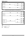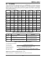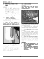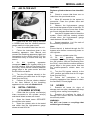
1
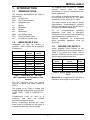
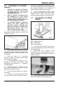
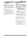
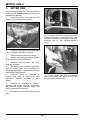
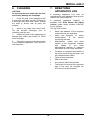
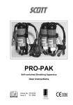
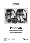
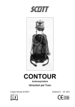
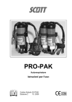
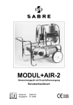
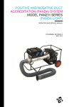
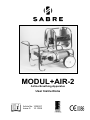
MODUL+AIR-2
Airline Breathing Apparatus
User Instructions
Article No. 1035027
Issue G 10. 2008
AS/NZS1716 : 2003
Lic. 1214 SAI Global
MODUL+AIR-2
Airline Breathing Apparatus
Contents
WARNINGS ..................................................................................................................................................ii
1.
INTRODUCTION.............................................................................................................................1
1.1
ABBREVIATIONS.......................................................................................................................1
1.2
BREATHABLE AIR .....................................................................................................................1
1.3
AIRLINE AIR SUPPLY ................................................................................................................1
1.4
APPARATUS DURATION...........................................................................................................2
1.5
TRAINING ..................................................................................................................................2
1.6
SERVICING................................................................................................................................2
1.7
SPARE PARTS AND ACCESSORIES ........................................................................................2
1.8
WARRANTY ...............................................................................................................................2
1.9
NOTIFIED BODIES.....................................................................................................................3
2.
TECHNICAL DESCRIPTION ..........................................................................................................3
2.1
GENERAL ..................................................................................................................................3
2.2
PNEUMATICS ............................................................................................................................4
2.3
PRESSURE REDUCER..............................................................................................................5
2.4
HOSE REEL ...............................................................................................................................5
2.5
MEDIUM-PRESSURE ALARM OPTIONS...................................................................................6
2.5.1
Whistle ..............................................................................................................................6
2.5.2
DS4 Alarm .........................................................................................................................6
2.6
EXTERNAL AIR SUPPLY ...........................................................................................................6
2.7
AIRLINE FILTER UNIT ...............................................................................................................6
2.8
HOSE CONFIGURATIONS ........................................................................................................7
2.9
CYLINDERS ...............................................................................................................................9
3.
PREPARATION FOR USE............................................................................................................10
3.1
INITIAL CHECKS - (AIRLINE SYSTEM)....................................................................................10
3.2
DS4 ALARM .............................................................................................................................10
3.3
AIR FILTER UNIT .....................................................................................................................11
3.4
INITIAL CHECKS - (CYLINDER SYSTEM) ...............................................................................11
3.5
HOSES .....................................................................................................................................11
3.6
CHANGING A CYLINDER ........................................................................................................12
3.7
ADJUSTING CYLINDER BANDS..............................................................................................12
3.8
CHANGING THE DS4 BATTERY..............................................................................................13
4.
DURING USE................................................................................................................................13
4.1
EXTERNAL AIR SUPPLY WITH CYLINDER BACK-UP ............................................................13
4.2
CYLINDER SUPPLY.................................................................................................................13
5.
AFTER USE ..................................................................................................................................14
6.
CLEANING ...................................................................................................................................15
7.
BREATHING APPARATUS LOG..................................................................................................15
8.
SCHEDULED MAINTENANCE .....................................................................................................16
8.1
MONTHLY ................................................................................................................................16
8.2
ANNUALLY...............................................................................................................................16
Sabre Breathing Apparatus is a division of Scott Health and Safety Limited.
Registered Office: Scott Health and Safety Limited, Pimbo Road, West Pimbo,
Skelmersdale, Lancashire, WN8 9RA, England.
i
WARNINGS
Please Read Carefully and Fully Understand
This manual is for use by personnel trained in the use and care of compressed air
breathing apparatus, and MUST NOT be used as a self-teaching guide by untrained users.
Failure to understand or adhere to the Modul+Air-2 User Instructions may result in injury
or death.
Scott Health and Safety Limited have taken great care to ensure that the information in
this manual is accurate, complete and clear. However, Training and Technical Support
Services will be pleased to clarify any points in the manual and answer questions on
Sabre breathing apparatus.
The following warnings are in accordance with certifying authority requirements and
apply to the use of breathing apparatus in general:
Ensure that the selection of the equipment to be used is sufficient for the
tasks being undertaken and the hazards likely to be encountered. For
guidance on the selection of apparatus to be used with the Modul+Air-2
system, please contact Training & Technical Support Services at Scott
Health and Safety Limited or refer to EN 529 : 2005 and the Health and Safety
Executive Publication HS(G)53 Respiratory Protective Equipment, A
Practical Guide for Users.
In Australia and New Zealand, ensure that your selection of respiratory
protective devices conform to the requirements of AS/NZS1715 : 1994.
Anti-static supply hoses MUST be used in potentially flammable or explosive
atmospheres.
The equipment is designed for use in a temperature range of -6°C to +60°C.
The storage temperature should be between -30°C and +60°C.
When the equipment is in use, a competent person MUST remain with the
supply system at all times to act as base controller and monitor the air
supply. Under no circumstances must the equipment be left unmanned
when wearers are being supplied from the unit.
To ensure optimum equipment performance, carry out the tests and service
procedures detailed in this Manual under Servicing and Scheduled
Maintenance.
Apparatus that fails a routine check must be withdrawn from service, an
explanatory note attached and the unit returned for repair.
DISCLAIMER
Failure to comply with these instructions or misuse of the apparatus may result in:
death, injury or material damage, and invalidate any warranty or insurance claims.
COPYRIGHT
This manual must not be copied in part or whole, or used for purposes other than its intended
purpose without the written permission of Scott Health and Safety Limited.
ii
MODUL+AIR-2
Air supplied from a fixed or portable
external
source
must
be
tested
periodically to ensure conformance with
these regulations.
1. INTRODUCTION
1.1
ABBREVIATIONS
The following abbreviations are used in
this manual:
AFU
Air Filter Unit
DS4
Low Pressure Alarm
DV
Demand Valve
m
Metres
mg
Milligrams
min
Minute
mm
Millimetres
NRV Non Return Valve
PRV
Pressure Relief Valve
psi
Pounds per Square Inch
1.2
Air supplied to breathing apparatus must
be free from the odour of oil. The odour
3
threshold is in the region of 0.3 mg/m .
The water content of air used to charge
high-pressure compressed-air cylinders
3
must not exceed 30 mg/m for 300 bar or
3
50 mg/m for 200 bar apparatus.
Air
for
compressed-air
breathing
apparatus must have a dew-point
sufficiently low to prevent internal freezing
when apparatus is used below 4°C.
National regulations for compressed
airline breathing apparatus must be
observed.
BREATHABLE AIR
Breathable Air may be natural or
synthetic. Table 1 shows the composition
of natural air.
Component
Mass %
(Dry Air)
1.3
Volume%
(Dry Air)
Oxygen
23.14
20.95
Nitrogen
75.52
78.08
Argon
1.288
0.934
Carbon Dioxide
0.048
0.031
Hydrogen
0.000 003
0.000 05
Helium
0.000 073
0.000 52
Neon
0.001 2
0.0001 8
Krypton
0.000 33
0.000 11
Xenon
0.000 04
0.000 009
AIRLINE AIR SUPPLY
Airline systems must conform to the
supply pressures and flow-rates listed in
Table 2. An airline flow tester, (Article
Number 1035978), can be used to check
airline supply pressure and flow.
Number of
Wearers
Pressure
bar (psi)
Flow
(L/min)
1
5.0 - 7.0 (70 - 130)
300
2 (1 Pair)
5.0 - 7.0 (70 - 130)
450
3 (1 + 1 pair)
5.0 - 7.0 (70 - 130)
750
4 (2 Pairs)
5.0 - 7.0 (70 - 130)
900
Table 2: Airline Supply Pressure and
Flow
Table 1: Breathable Air - EN 12021
(NOT applicable for Australia or New
Zealand)
Modul+Air-2 is approved for use with a
maximum hose length of 105 metres.
Fire risk increases when the oxygen
content is above the value shown in
Table 1.
The quality of air used to supply and
charge breathing apparatus must conform
to EN 12021 : 1999 or AS/NZS1715 :
1994.
Contaminants must be kept to a
minimum, and must not exceed
permissible exposure levels.
Where air-purifying devices are used,
these must be sufficient for the types of
contaminant present in the air supply.
1
MODUL+AIR-2
1.4
APPARATUS DURATION
1.6
Durations quoted for compressed-air
cylinders are nominal and based on an
average consumption rate of 40 litres per
minute to positive-pressure breathing
apparatus. Table 3 lists the cylinders
approved for use with Modul+Air-2.
Consumption rates are increased by the
following factors:
•
Workload.
•
Temperature: extreme heat or cold.
•
Physical fitness: personnel, with
less
efficient
cardiovascular
systems, consume more air for a
given work rate.
•
Stress and fatigue.
•
Physiological stress.
•
Heavy/restrictive clothing.
Training and Technical Support
Services at Scott Health and Safety
Limited provide a complete mobile test
and maintenance service for all Sabre
equipment.
Further details of training courses and
servicing contracts can be obtained from
Training and Technical Support
Services.
It is important that users are aware of
these factors when considering the
duration of air supply from cylinders, and
ensure that adequate precautions are
taken.
1.5
SERVICING
Modul+Air-2 must be serviced at
scheduled intervals by personnel who
have completed a formal training course
and hold a current certificate for the
servicing and repair of Sabre breathing
apparatus. Details of the servicing
schedule are contained in the Modul+Air2 Service Manual, copies of which can
only be obtained by registered holders of
a current certificate.
1.7
SPARE PARTS AND
ACCESSORIES
Customer Services provide an efficient,
friendly, customer contact point for
ordering new apparatus, spare parts and
accessories. The team can also provide
general information on Sabre products.
TRAINING
Personnel using this apparatus must be
fully-trained in accordance with these
instructions and national regulations.
1.8
These instructions cannot replace an
accredited training course run by fully
qualified instructors in the proper and
safe use of Sabre breathing apparatus.
WARRANTY
Please contact Training and Technical
Support Services or your distributor for
training course details.
The products manufactured at our
factories in Skelmersdale and Vaasa
carry a warranty of 12 months (unless
stated otherwise) for parts, labour and
return to site. The warranty period runs
from the date of purchase by the end
user.
Training and Technical Support
Services:
Scott Health and Safety Limited
Pimbo Road,
West Pimbo,
Skelmersdale,
Lancashire,
WN8 9RA,
England.
These products are warranted to be free
from
defects
in
materials
and
workmanship at the time of delivery.
SCOTT will be under no liability for any
defect arising from wilful damage,
negligence, abnormal working conditions,
failure
to
follow
the
original
manufacturer’s instructions, misuse or
unauthorised alteration or repair.
Tel: +44 (0) 1695 711711
Fax: +44 (0) 1695 711775
Evidence of purchase date will need to be
provided for any claims arising during the
warranty period. All warranty claims must
be directed through SCOTT Customer
Services and in accordance with our
sales return procedure.
2
MODUL+AIR-2
1.9
NOTIFIED BODIES
2. TECHNICAL
DESCRIPTION
Inspec International Ltd (0194)
56 Leslie Hough Way,
Salford,
Greater Manchester,
M6 6AJ,
England.
2.1
GENERAL
British Standards Institute (0086)
389 Chiswick High Road,
London,
W4 4AL,
England.
SAI Global
286 Sussex Street,
Sydney,
NSW 2000,
Australia.
Lic. No 1214.
Modul+Air-2, Two-cylinder Trolley
The Modul+Air-2 apparatus is a portable
airline system which can supply mediumpressure breathable quality air to up-to
four airline breathing apparatus with
demand valves.
Modul+Air-2 units are approved for use
with a total hose length of up-to 105
metres. Apparatus with two reducers is
approved for use with two total hose
lengths of 105 metres, where each length
is supplied from a reducer.
Modul+Air-2 units are approved for use
with all Sabre compressed-air airline
breathing apparatus fitted with demand
valves.
The
following
configurations
of
Modul+Air-2 are available:
•
Static frame fitted with pneumatics
and space for two compressed-air
cylinders.
•
Static frame fitted with pneumatics
and space for four compressed-air
cylinders.
•
Trolley-based system with 2 or 4
cylinder frame, pneumatics and a
hose reel capable of holding 60
metres of hose.
•
Trolley system with cylinders,
pneumatics and a hose reel, that
can be supplied from an external
medium-pressure breathable air
supply.
3
MODUL+AIR-2
Options for use with trolley-based
versions include:
•
A
medium-pressure
warning
whistle;
•
An Air Filter Unit (AFU);
•
An electronic low-pressure warning
alarm (DS4).
The Modul+Air-2 tubular stainless steel
frame can house either two or four
compressed-air
cylinders
(version
dependent) with a diameter of between
140 mm (5.5“) and 180 mm (7”).
Cylinders are secured by steel cylinder
bands and butterfly catches.
Modul+Air-2 is 'CE' marked to EN 139 :
1994 (Respiratory Protective Devices Compressed Airline Breathing Apparatus)
and is quality-assurance approved to:
ISO 9001 : 2000.
Modul+Air-2 is approved to Australian/
New Zealand Standard AS/NZS1716 :
2003.
Key
Modul+Air-2 is marked in accordance
with EN 139 : 1994 and AS/NZS1716 :
2003. An explanation of those markings is
shown opposite:
Meaning
A=
Product brand name
B=
Symbol - refer to User Instructions
C=
Operational warnings
D=
Contact details of manufacturer
E=
Product model/designation
F=
Apparatus description
G=
Standards to which apparatus is certified
H=
Serial number of apparatus
I=
Date of manufacture
J=
Number of Approval Body
2.2
PNEUMATICS
The pneumatics system comprises
cylinder connectors and reducer.
Air flows from the cylinders, through the
cylinder connectors to the reducer where
it is reduced to between 5.5 and 11 bar.
Each cylinder connector has a non-return
valve that prevents air from a charged
cylinder flowing into a discharged cylinder
and allows discharged cylinders to be
replaced while the system is pressurised.
A bleed screw in the connector elbow
enables the cylinder connector to be
depressurised prior to disconnection.
A sintered filter in the cylinder connector
protects the pneumatic system from
contamination.
4
MODUL+AIR-2
2.3
PRESSURE REDUCER
The pressure reducer is a single stage
spring and piston device with an internal
pressure relief valve that protects the
medium-pressure system from overpressurisation.
There are ports in the reducer which
accommodate:
•
An outlet to the medium-pressure
gauge;
•
A medium-pressure outlet to the
wearers;
•
The medium-pressure inlet from an
external supply or an AFU
(optional);
•
An outlet to the medium-pressure
warning whistle (optional).
Pneumatics for a single reducer
system
Air from the cylinder flows through the
high-pressure manifold, enters the
reducer through a jet and flows through
the hollow piston stem to a chamber
above the piston. As pressure in the
chamber rises, the piston is forced down
against the spring until the nylon seat at
the lower end of the piston stem closes
the jet.
Pneumatics for a dual reducer system
Systems designed to supply 4 wearers
are provided with 2 pressure-reducers to
ensure sufficient flow-rate. The reducers
are connected to a common highpressure manifold.
When medium-pressure air flows from the
reducer to the wearers, the pressure in
the chamber falls enabling the spring to
lift the piston seat from the jet. This cycle
continues while there is sufficient air in
the cylinder.
The high-pressure manifold has ports that
can accommodate:
•
Outlets for up-to two pressure
reducers;
•
Inlets for up-to four cylinder
connectors;
•
An outlet for a high-pressure
warning whistle;
•
An outlet for a high-pressure
gauge.
The medium-pressure gauge has a
restrictor that limits air-loss to 25 litres per
minute in the event of the gauge
becoming damaged.
2.4
HOSE REEL
The hose reel is fitted with 60 metres of
9.5 mm (3/8") bore airline supply hose.
The hose conforms to EN 139 : 1994 and
AS/NZS1716 : 2003; and has a maximum
working pressure of 15 bar (220psi).
Hoses are fitted with CEJN safety
couplings.
Systems that do not use all ports have
blanking plugs fitted to unused ports.
Medium-pressure air is output by the
reducer, either directly to wearer supply
airlines, or, on hose reel versions, to a
manifold on the hose reel hub.
The
hose
reel
manifold
can
accommodate
up-to
two
mediumpressure hoses, each from a pressure
reducer; and a medium-pressure warning
whistle.
The high-pressure warning whistle
sounds when pressure in the on-line
cylinder falls below 55 bar.
5
MODUL+AIR-2
A rotatable CEJN coupling in the hub
allows the hose reel to turn without loss of
air.
audible alarm will sound until pressure in
the system reaches the safe level. Once
the safe pressure level is reached, the
audible alarm will cancel automatically,
the red light will extinguish and a green
light will illuminate.
The CEJN parking connector at the top of
the hose reel frame is designed to vent
any pressure from the medium-pressure
circuit.
During use, if the medium-pressure circuit
falls to below 4.5 bar (65psi), the operator
is alerted by the illumination of the red
warning light and the sounding of the
audible alarm. Under ‘normal’ conditions,
(while the pressure is at a safe level), a
green light is illuminated.
Anti-static hoses (which are resistant to
heat and chemicals) must be used in
environments where there is danger from
potentially explosive or flammable
atmospheres.
2.5
2.5.1
MEDIUM-PRESSURE
ALARM OPTIONS
2.6
WARNING:
•
On
Modul+Air-2
versions
designed to operate with an
external supply airline, the airline
may be connected directly to a
pressure-reducer or to an airline
filter unit provided.
•
External air supplies must
conform to EN 12021 : 1999 or
AS/NZS1715 : 1994. Pressure
must be between 6.0 and 9.0 bar
(84 and 126psi) and capable of
providing the flow-rates listed in
Table 2.
Whistle
The medium-pressure whistle sounds
when the medium-pressure circuit falls
below between 4.1 bar (60psi) and 3.8
bar (55psi).
2.5.2
EXTERNAL AIR SUPPLY
DS4 Alarm
The DS4 alarm is a battery-operated
electronic warning device which is ATEXapproved as intrinsically safe for use in
flammable or explosive atmospheres.
2.7
AIRLINE FILTER UNIT
DS4 Alarm
The DS4 is powered by a PP3 9-volt
alkaline battery, which must be renewed
periodically. A yellow light will illuminate
to advise the operator when the battery
level is low.
Airline Filter Unit (AFU)
[1]
[2]
[3]
[4]
The DS4 unit is switched on and off by a
key-operated switch which is located on
the side of the unit, close to the warning
lights.
When the DS4 is initially switched on, a
red warning light will illuminate and the
6
External Air Supply Inlet
Pop-up Indicator
Outlet Hoses
Warning Whistle
MODUL+AIR-2
WARNING:
•
The AFU WILL NOT remove
carbon monoxide (CO), carbon
dioxide (CO2), or other toxic
gases or vapours.
•
The AFU MUST be operated in
the vertical position. For further
details, please refer to AFU User
Instruction Manual.
2.8
HOSE
CONFIGURATIONS
Although the hose reel holds only 60
metres of hose, the maximum hose
length for which Modul+Air-2 is approved
is 105 metres. The total length is
achieved by connecting several hoses of
different lengths. The following diagrams
show configurations that have been
tested and approved by Scott Health and
Safety Limited.
The AFU has three filter elements.
Two coalescing filter elements remove oil,
-6
water, and particles down to 0.01 x 10
metres, giving a residual oil content of
3
less than 0.01 mg/m dirt.
Configurations that result in a total length
of less than 105 metres are permissible.
If
the
maximum
hose
length
configurations in the following diagrams
do not meet your requirements, please
contact Training and Technical Support
Services at Scott Health and Safety
Limited for advice on alternative
configurations.
The third element is an activated carbon
absorption filter that removes oil vapour
and odours.
Before use, the external air supply MUST
be checked for purity and composition
(see Breathable Air in the Introduction
section of this Manual). Where toxic
gases or vapours are present, an air
purifier must be used. Further details are
available from Customer Services at
Scott Health and Safety Limited.
Auto-drain valves fitted to each element,
drain water and oil filtered from the air.
The third element (an absorption bed of
activated carbon) removes oil vapour and
odours.
Elements must be renewed when
congested. A red pop-up indicator on
AFU is activated when the pressure drop
in the AFU, caused by congestion,
becomes excessive.
7
MODUL+AIR-2
Maximum hose length configuration for a 2-man Modul+Air-2
Maximum hose length configuration for a 4-man Modul+Air-2
Key:
HPM =
R=
BA =
High-pressure Manifold
Reducer
Breathing Apparatus
8
MODUL+AIR-2
2.9
CYLINDERS
Table 3 shows the cylinder types approved for use with Modul+Air-2. All durations quoted are
nominal and based on an average consumption rate of 40 litres per minute. (Composite
cylinders may vary in diameter which may affect the cylinder band positions, as would the
fitting of cylinder covers. The positions given are for guidance only). Table 4 contains details
of the cylinder specifications.
Cylinder
Water
volume
(litres)
Charging
pressure
(bar)
Free air
capacity
(litres)
Charged
weight
(kg)
Total
duration
(min)
Warning
period
(min)
Nominal
duration
(min)
Cylinder
Band
position
CYL-1200
6.0
200
1200
8.8
30
8
22
3
CYL-HWG1200
6.0
200
1200
7.2
30
8
22
3
CYL-FWC1300
4.7
300
1300
5.0
32
7
25
4
CYL-1640
6.0
300
1640
5.0
32
7
33
4
CYL-HWG1640
6.0
300
1640
5.8
41
8
33
3
CYL-FWC1640
6.0
300
1640
5.8
41
8
33
7
CYL-1800
9.0
200
1800
13.0
45
12
33
14
CYL-HWG1800
9.0
200
1800
11.2
45
12
33
14
CYL-FWC1800
9.0
200
1800
6.75
45
12
33
14
CYL-FWC1860
6.8
300
1860
6.75
46
9
37
7
CYL-2240
11.0
200
2240
13.0
45
12
33
14
CYL-FWC2460
11.0
300
2460
8.8
62
12
50
14
Table 3: Cylinders approved for use with Modul+Air-2
Code
Material
Specification
No Code
Steel (eg: CYL-1200)
CE Marked (EU)
Work Cover (Australia & New Zealand)
HWG
Hoop Wrapped Glass Fibre (eg: CYL-HWG-1200)
HSE-AL-HW1 (EU)
Work Cover (Australia & New Zealand)
FWC
Fully Wrapped Carbon Fibre (eg: CYL-FWC-1300)
CE Marked (EU)
Work Cover (Australia & New Zealand)
Table 4: Cylinder Codes and Specifications
The following formulae apply:
Total Duration =
Nominal Duration =
Warning Period =
Cylinder Free Air Capacity
Average Wearer Consumption Rate
Total Duration minus the Warning Period
Whistle Operating Pressure x Cylinder Water Capacity
Average Wearer Consumption Rate
High-pressure whistle operating pressure = 55 bar
Please read Section 1.4 - Apparatus Duration at the front of this manual.
9
MODUL+AIR-2
3.2
3. PREPARATION FOR
USE
WARNING:
•
Keep the AFU upright during
operation. Tilting the AFU may
result in filtered-out material reentering the air supply.
•
3.1
DS4 ALARM
WARNING:
The sound emitted by the DS4 alarm is
VERY loud. Warn others before
activating the alarm.
DO NOT use apparatus that fails
any of the following tests.
Withdraw the unit from service,
attach an explanatory note and
return for servicing.
INITIAL CHECKS (AIRLINE SYSTEM)
1.
Check that the apparatus is clean
and free from damage.
2.
Check that the apparatus is
complete, that the cylinders are fullycharged and that the cylinder valves and
bleed screws are closed (fully clockwise).
1.
Activate the DS4 alarm by inserting
the key into the switch and turning the key
in a clockwise direction.
2.
Confirm that the red warning light
illuminates and the audible alarm sounds.
3.
Connect Modul+Air-2 to the external
air supply.
4.
Once the safe pressure level is
reached, confirm that the DS4 resets from
the alarm condition; (i.e. the audible alarm
ceases, the red light extinguishes and the
green light illuminates).
5.
Ensure that the yellow light IS NOT
illuminated. If the yellow light illuminates,
the battery level is low and battery
replacement is required. Please refer to
Section 3.8 in this Manual for further
details.
WARNING:
•
DO NOT use the equipment if the
yellow (low battery level) warning
light is illuminated.
•
DO NOT remove the DS4 battery
compartment cover in a potentially
explosive
or
flammable
atmosphere.
3.
Check that the AFU sight-glasses are
clean and dry. If required, follow the
instructions given in the AFU User Manual
to clean them.
4.
Check that the external air supply is
pressurised and that the quality of air
conforms to the requirements detailed in
Section 1.2 of this Manual.
10
MODUL+AIR-2
3.3
WARNING:
Replace cylinders that are less than 80%
full.
AIR FILTER UNIT
4.
Check to ensure that there are no
leaks from the open bleed screw.
5.
Allow 30 seconds for the system to
pressurise. Close the cylinder valve and
bleed screw.
6.
Observe the high-pressure gauge
and check that pressure loss is less than 10
bar per minute. A drop of more than 10 bar
per minute indicates that there is a leak.
7.
Use the DV bypass valve to bleed the
system. Check that the warning whistle
sounds when the high-pressure gauge
reads between 50 and 60 bar.
1.
Check that the AFU pop-up indicator
is GREEN and that the medium-pressure
gauge needle is in the green sector.
2.
8.
Repeat operations 1 to 6 for each of
the remaining cylinders in turn.
Note:
Ensure that air is drained through the DV
bypass valve before commencing tests on
next cylinder.
Listen for audible leaks from the unit.
3.
Follow the instructions given in the
breathing apparatus User Manual and
connect the breathing apparatus pigtail and
facemask(s) to the airline hose(s). Pull the
connections firmly to ensure that they are
secure.
9.
breathing
apparatus
4.
On
ALL
connected, turn the DV bypass valve(s) to
the ‘ON’ position. With air free-flowing from
the DV(s), check that the medium-pressure
gauge stays in the green sector and that
the DS4 does not alarm.
11. Turn the DV bypass valve(s) to the
‘OFF’ position and check that air no longer
flows from the DV(s).
5.
Turn the DV bypass valve(s) to the
‘OFF’ position and check that air no longer
flows from the DV(s).
12. Follow the instructions in the
breathing apparatus User Manual to check
the facemask, DV and pigtail.
6.
Perform all pre-use checks detailed
in the User Manual of the breathing
apparatus to be used with Modul+Air-2.
3.4
Open one cylinder valve fully.
breathing
apparatus
10. On
ALL
connected, turn the DV bypass valve(s) to
the ‘ON’ position. With air free-flowing from
the DV(s), check that the medium-pressure
gauge stays in the green sector and that
the medium-pressure whistle does not
alarm.
3.5
INITIAL CHECKS (CYLINDER SYSTEM)
HOSES
1.
Examine all hoses for signs of
damage such as splits, abrasions and deep
crazing (minor crazing is acceptable).
1.
Check that the cylinder connector(s)
is/are connected to the cylinder valve(s)
and that all bleed screws are closed.
2.
Examine all couplings for signs of
damage and ensure that all connections
are securely made.
2.
Open the bleed screw OPPOSITE
the cylinder to be tested.
WARNING:
DO NOT use hoses or couplings that
exhibit signs of damage.
3.
Open the cylinder valve to be tested
and check that the high-pressure gauge
shows at least 80% full.
11
MODUL+AIR-2
3.6
catch 90° clockwise and folding the catch
flat. (Minor adjustments can be made using
the cam-lock fastener: turn clockwise to
tighten and anti-clockwise to loosen).
CHANGING A CYLINDER
WARNING:
•
DO NOT mix cylinders of different
charging pressures when using
the equipment. Fit only FULLYCHARGED cylinders.
•
When a cylinder is changed while
the apparatus is in use, ensure
that an adequate supply of air is
available in the on-line cylinder for
breathing apparatus wearers.
•
8.
On the replacement cylinder, open
the cylinder valve the close the on-line
cylinder valve. Check that the highpressure gauge reading is at least 80% full.
3.7
ADJUSTING CYLINDER
BANDS
To prevent possible equipment
failure, DO NOT charge the
pneumatic system utilising more
than one cylinder or operate the
Modul+Air-2 system with more
than one cylinder valve open.
1.
On the empty cylinder, release the
hand-wheel locking catch and close the
cylinder valve (A).
[1]
[2]
[3]
[4]
Cylinder Band
Retaining Screw
Cradle Flap
Locking Catch
1.
Use a 4mm Allen Key to remove the
cylinder band retaining screw and release
the cylinder band.
2.
Open bleed screw (B) to vent the
cylinder connector. Close the bleed screw
and disconnect the cylinder connector from
the cylinder.
2.
Re-position
the
cylinder
band
according to the hole-positions given in
Table 3. Replace the retaining screw and
tighten securely.
3.
With the frame in a horizontal
position, release the cylinder band catch
and remove the cylinder.
4.
If the replacement cylinder is of a
different size, adjust the cylinder band
accordingly (see Section 3.7 - Adjusting
Cylinder Bands).
5.
Slide the charged cylinder into the
frame, ensuring that it is correctly located
against the end of the frame.
6.
Fit and securely tighten the cylinder
connector.
7.
Position the cylinder band around the
cylinder and secure by turning the butterfly
3.
Position the cylinder in the frame and
fasten the cylinder band butterfly catch.
12
MODUL+AIR-2
3.8
CHANGING THE DS4
BATTERY
4. DURING USE
WARNING:
When in use, a competent person MUST
remain with the supply system at all
times to act as base controller and
monitor the air supply. Under NO
circumstances must the equipment be
left unmanned when wearers are being
supplied from the unit.
WARNING:
DO NOT remove the DS4 battery
compartment cover in a potentially
explosive or flammable atmosphere.
1.
Remove the four screws that secure
the battery compartment cover to the DS4
unit. Place battery compartment cover
aside.
4.1
2.
Withdraw the battery and holder from
the battery compartment.
3.
Remove the battery from the holder.
EXTERNAL AIR SUPPLY
WITH CYLINDER BACKUP
If the low-pressure alarm sounds (DS4 or
medium-pressure whistle), or if the
medium-pressure gauge falls below 5 bar:
4.
Replace the battery in the holder and
refit into the battery compartment.
5.
Replace the battery compartment
cover and secure in position with the four
screws. Tighten screws evenly, DO NOT
over-tighten.
1.
Fully open one cylinder valve.
2.
Check that the high-pressure gauge
reading is greater than 80% and that
medium-pressure gauge is above 5 bar.
3.
If required, disconnect the external
air supply.
4.2
CYLINDER SUPPLY
If the high-pressure
sounds:
warning
whistle
1.
Open the next designated cylinder
valve fully.
2.
Close the cylinder valve and open the
bleed screw on the empty cylinder.
3.
Follow the instructions in Section 3.6
to replace the empty cylinder.
4.
Mark the empty cylinder accordingly
and store separately from full cylinders.
13
MODUL+AIR-2
5. AFTER USE
The following procedure covers all options
available with Modul+Air-2 and covers the
apparatus in general.
1.
Close the cylinder valve and open the
bleed screw on the active cylinder.
10. Connect the hose CEJN outlet to the
parking connector on the hose reel. This
prevents the hose unwinding and vents any
pressure left in the medium-pressure
circuit.
2.
Switch off the DS4 unit by turning the
key in a counter-clockwise direction.
3.
Disconnect the external air supply.
4.
Open the breathing apparatus bypass
and vent air from the pneumatics.
5.
Replace used cylinders with fullycharged cylinders.
6.
Disconnect the breathing apparatus
from the airline. Clean, test and inspect the
breathing apparatus in accordance with the
appropriate User Manual.
7.
Examine hoses for damage or
excess wear such as splits, kinks and
abrasions. Replace damaged or worn
hoses.
11. Firmly grasp and pull the winding
handle knob away from the hose reel. Fold
the knob against the handle.
8.
Examine all couplings for wear or
damage and ensure that all connections
are securely made. Replace items with
worn or damaged connectors.
9.
Rewind the airline hose onto the hose
reel.
14
MODUL+AIR-2
6. CLEANING
7. BREATHING
APPARATUS LOG
CAUTION:
Do not drop the hose ends onto the floor
as this may damage the couplings.
A breathing apparatus Log must be
maintained for each apparatus and must be
retained for future reference.
1.
Clean all parts of the apparatus with
a mild soap and water solution, followed by
a thorough rinse with clean water. Unwind
the hose to ensure that all parts are
cleaned.
A breathing apparatus Logbook, is
available from Scott Health and Safety
Limited (under Article Number 1034745)
for this purpose.
2.
Allow to dry away from direct heat.
Dry the air-hose thoroughly prior to
rewinding onto the reel.
The log must contain:
•
Name and address of the employer
responsible for the apparatus.
•
Name and signature, or unique
authentication,
of
the
person
conducting the tests.
•
Manufacturer, model and serial
number of the equipment, together
with
details
of
any
other
distinguishing features or markings
that enable it to be clearly identified.
•
Condition of equipment and details of
any faults found during the tests, and
any remedial action taken.
•
Types of test conducted.
•
Date of the tests.
•
Air pressure within the cylinders.
•
The length of time that the equipment
was in use must be recorded (for
AFU servicing requirements).
3.
Inspect all parts of the apparatus for
damage and check the function of CEJN
hose couplings.
4.
Follow the cleaning instructions given
in the breathing apparatus, DS4 and AFU
User Manuals.
15
MODUL+AIR-2
8.2
8. SCHEDULED
MAINTENANCE
8.1
ANNUALLY
1.
The equipment must be tested and
serviced
in
accordance
with
the
Modul+Air-2 Service Schedule, within a
maximum period of one year.
MONTHLY
1.
The equipment must be checked and
tested at monthly intervals in accordance
with the After Use instructions contained in
this Manual.
2.
Full details of servicing requirements
can be found in the Modul+Air-2 Service
Manual, which is available from Training
and Technical Support Services at Scott
Health and Safety Limited upon
completion of a formal training course in
maintenance of the apparatus.
2.
Details of these tests must be
recorded within the appropriate register and
retained for future reference.
Note:
In the United Kingdom, monthly testing is a
statutory requirement under COSHH
(Control of Substances Hazardous to
Health) regulations.
3.
In order to maintain correct
functioning of the equipment, if it is
subjected to excessive use, it may be
necessary to test the equipment on a more
frequent basis than that stipulated.
16
Sabre Breathing Apparatus
Scott Health and Safety Limited
Pimbo Road, West Pimbo,
Skelmersdale, Lancashire,
WN8 9RA, England.
Tel: +44 (0) 1695 711711
Fax: +44 (0) 1695 711775