1
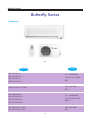
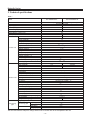
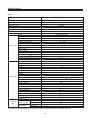
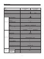
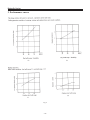
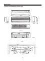
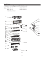
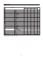
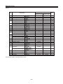
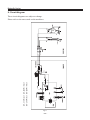
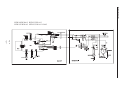
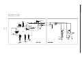
Butterfly Series
Butterfly Series
1. Summary
Fig. 1
NOTE
MODEL
KF-23GW/A13
CE STANDARD
KFR-23GW/A13
KF-26GW/A13
1Ph 220-230V 50Hz
R22
KFR-26GW/A13
1Ph 240V 50Hz
R22
KFR-23GW/A13-12405
KF-20GW/NA13
CE STANDARD
KFR-20GW/NA13
KF-25GW/NA13
1Ph 220-230V 50Hz
R407C
KFR-25GW/NA13
KF-23GW/A13-12206
KF-26GW/A13-12206
1Ph 220V 60Hz
R22
-1-
Butterfly Series
2. Technical specifications
Table 1
Model
KF-23GW/A13
KFR-23GW/A13
Cooling/Heating
1Ph 220-230V 50Hz
2300/2400
2300
800/850
800
3.5/3.7
3.5
420
0.8
2.87/2.82
2.87
KFR-23G/A13
KF-23G/A13
1090/930
13
Cross flow fan-1
97 538
Aluminum fin-copper tube
1.5
0.13
MP24GA
2
Controller 3.15A Transformer 0.2A
1
37
710 180 250
7
KFR-23W/A13
KF-23W/A13
770/820
770
3.4/3.6
3.4
16
Capillary
KH134VFRC
780
Internal overload protection
Capacitor starting
Exhaust temperature 115
Aluminum fin-copper
9.52
0.3
950
Axial fan-1
320
Auto defrost
52
720 260 430
25
R22/0.65
R22/0.55
4
6
9.52
5
10
Cooling
Function
Power supply
Capacity (W)
Rated input (W)
Rated current (A)
Air flow (m3/h)
Dehumidifying volume (L/h)
C.O.P (W/W)
Model
Motor fan speed(rpm)
Output power(W)
Fan type/piece
Diameter-length(mm)
Evaporator
Row-fin distance(mm)
Indoor unit
Working area(m2)
Swing motor
Input power(W)
Fuse(A)
Working capacitor( F)
Noise(dB(A))
Dimension(width-height-depth)(mm)
Net weight(kg)
Model
Input power(W)
Current(A)
L.R.A.(A)
Throttling method
Compressor
Compressor power (W)
Protector
Outdoor unit Starting method
Working temp.
Condenser
Pipe-diameter (mm)
Working area(m2)
Fan motor speed(rpm)
Type-piece
Diameter(mm)
Defrosting method
Noise (dB(A))
Dimension(width-height-depth)(mm)
Net weight(kg)
Refrigerant charge (kg)
Length (m)
Outer diameter of Liquid pipe(mm)
Connecting
connecting pipe
Gas pipe(mm)
pipe
Height(m)
Max distance
Length(m)
The technical data are subject to change without notice .Please refer to the nameplate of the unit.
-3-
Butterfly Series
Table 2
Model
KF-26GW/A13
KFR-26GW/A13
Cooling/Heating
1Ph 220-230V 50Hz
2600/3000
2600
1000/1050
1000
4.4/4.6
4.4
420
1.0
2.60/2.86
2.6
KFR-26G/A13
KF-23G/A13
1090/930
13
Cross flow fan-1
97 538
Aluminum fin-copper tube
1.5
0.13
MP24GA
2
Controller 3.15A Transformer 0.2A
1
37
710 180 250
7
KFR-26W/A13
KF-26W/A13
970/1020
970
4.3/4.5
4.3
22
Capillary
RH174VHAC
2P17S225ANA
885
Outernal overload protection
Capacitor starting
Exhaust temperature 115
Aluminum fin-copper
9.52
0.3
950
Axial fan-1
320
Auto defrost
52
720 260 430
32
25
R22/0.9
R22/0.65
4
6
9.52
5
10
Cooling
Function
Power supply
Capacity (W)
Rated input (W)
Rated current (A)
Air flow (m3/h)
Dehumidifying volume (L/h)
C.O.P (W/W)
Model
Motor fan speed(rpm)
Output power(W)
Fan type/piece
Diameter-length(mm)
Evaporator
Row-fin distance(mm)
Indoor unit
Working area(m2)
Swing motor
Input power(W)
Fuse(A)
Working capacitor( F)
Noise(dB(A))
Dimension(width-height-depth)(mm)
Net weight(kg)
Model
Input power(W)
Current(A)
L.R.A.(A)
Throttling method
Compressor
Compressor power (W)
Protector
Outdoor unit Starting method
Working temp.
Condenser
Pipe-diameter (mm)
Working area(m2)
Fan motor speed(rpm)
Type-piece
Diameter(mm)
Defrosting method
Noise (dB(A))
Dimension(width-height-depth)(mm)
Net weight(kg)
Refrigerant charge (kg)
Length (m)
Outer diameter of Liquid pipe(mm)
Connecting
connecting pipe
Gas pipe(mm)
pipe
Height(m)
Max distance
Length(m)
The technical data are subject to change without notice .Please refer to the nameplate of the unit.
-4-
Butterfly Series
Table 3
KFR-23GW/A13-12405
Model
Cooling/Heating
1Ph 240V 50Hz
2300/2400
820/800
3.5/3.4
380
1.0
2.82/3.00
KFR23G/A13-12405
1080/980/910
13
Cross flow fan-1
97 538
Aluminum fin-copper tube
1.5
0.13
MP24GA
2
Controller 3.15A Transformer 0.2A
1
37
710 180 250
7
KFR-23W/A13-12405
790/770
3.3/3.3
23
Capillary
KH134VFRC
780
Internal overload protection
Capacitor staring
Exhaust temperature 115
Aluminum fin-copper
9.52
0.3
950
Axial fan-1
320
Auto defrost
52
720 260 430
25
R22/0.65
4
6
9.52
5
10
Function
Power supply
Capacity (W)
Rated input (W)
Rated current (A)
Air flow (m3/h)
Dehumidifying volume (L/h)
C.O.P (W/W)
Model
Motor fan speed(rpm)
Output power(W)
Fan type/piece
Diameter-length(mm)
Evaporator
Row-fin distance(mm)
Indoor unit
Working area(m2)
Swing motor
Input power(W)
Fuse(A)
Working capacitor( F)
Noise(dB(A))
Dimension(width-height-depth)(mm)
Net weight(kg)
Model
Input power(W)
Current(A)
L.R.A.(A)
Throttling method
Compressor
Compressor power (W)
Protector
Outdoor unit Starting method
Working temp.
Condenser
Pipe-diameter (mm)
Working area(m2)
Fan motor speed(rpm)
Type-piece
Diameter(mm)
Defrosting method
Noise (dB(A))
Dimension(width-height-depth)(mm)
Net weight(kg)
Refrigerant charge (kg)
Length (m)
Outer diameter of Liquid pipe(mm)
Connecting
connecting pipe
Gas pipe(mm)
pipe
Height(m)
Max distance
Length(m)
The technical data are subject to change without notice .Please refer to the nameplate of the unit.
-5-
Butterfly Series
Table 4
Model
KF-20GW/NA13
KFR-20GW/NA13
Cooling/Heating
1Ph 220-230V 50Hz
2000/2300
2000
850/880
850
3.70/3.83
3.70
420
0.8
2.35/2.88
2.35
KFR-20G/NA13
KF-20G/NA13
1090/930
13
Cross flow fan-1
97 538
Aluminum fin-copper tube
1.5
0.13
MP24GA
2
Controller 3.15A Transformer 0.2A
1
37
710 180 250
7
KFR-20W/NA13
KF-20W/NA13
820/770
820
3.57/3.35
3.57
19
Capillary
C-1RN70H5C
785
Outernal overload protection
Capacitor starting
Exhaust temperature 115
Aluminum fin-copper
9.52
0.3
950
Axial fan-1
320
Auto defrost
53
720 260 430
25
R407C/0.65
R407C/0.58
4
6
9.52
5
10
Cooling
Function
Power supply
Capacity (W)
Rated input (W)
Rated current (A)
Air flow (m3/h)
Dehumidifying volume (L/h)
C.O.P (W/W)
Model
Motor fan speed(rpm)
Output power(W)
Fan type/piece
Diameter-length(mm)
Evaporator
Row-fin distance(mm)
Indoor unit
Working area(m2)
Swing motor
Input power(W)
Fuse(A)
Working capacitor( F)
Noise(dB(A))
Dimension(width-height-depth)(mm)
Net weight(kg)
Model
Input power(W)
Current(A)
L.R.A.(A)
Throttling method
Compressor
Compressor power (W)
Protector
Outdoor unit Starting method
Working temp.
Condenser
Pipe-diameter (mm)
Working area(m2)
Fan motor speed(rpm)
Type-piece
Diameter(mm)
Defrosting method
Noise (dB(A))
Dimension(width-height-depth)(mm)
Net weight(kg)
Refrigerant charge (kg)
Length (m)
Outer diameter of Liquid pipe(mm)
Connecting
connecting pipe
Gas pipe(mm)
pipe
Height(m)
Max distance
Length(m)
The technical data are subject to change without notice .Please refer to the nameplate of the unit.
-6-
Butterfly Series
Table 5
Model
KF-25GW/NA13
KFR-25GW/NA13
Cooling/Heating
1Ph 220-230V 50Hz
2500/2800
2500
980/1030
980
4.3/4.5
4.3
420
0.8
2.55/2.72
2.55
KFR-25G/NA13
KF-25G/NA13
1090/930
13
Cross flow fan-1
97 538
Aluminum fin-copper tube
1.5
0.13
MP24GA
2
Controller 3.15A Transformer 0.2A
1
37
710 180 250
7
KFR-25W/NA13
KF-25W/NA13
950/1000
950
4.14/4.35
4.14
24
Capillary
C-RV167H01AA
940
Outernal overload protection
Capacitor starting
Exhaust temperature 115
Aluminum fin-copper
9.52
0.3
950
Axial fan-1
320
Auto defrost
55
720 260 430
32
R407C/0.95
R407C/0.95
4
6
9.52
5
10
Cooling
Function
Power supply
Capacity (W)
Rated input (W)
Rated current (A)
Air flow (m3/h)
Dehumidifying volume (L/h)
C.O.P (W/W)
Model
Motor fan speed(rpm)
Output power(W)
Fan type/piece
Diameter-length(mm)
Evaporator
Row-fin distance(mm)
Indoor unit
Working area(m2)
Swing motor
Input power(W)
Fuse(A)
Working capacitor( F)
Noise(dB(A))
Dimension(width-height-depth)(mm)
Net weight(kg)
Model
Input power(W)
Current(A)
L.R.A.(A)
Throttling method
Compressor
Compressor power (W)
Protector
Outdoor unit Starting method
Working temp.
Condenser
Pipe-diameter (mm)
Working area(m2)
Fan motor speed(rpm)
Type-piece
Diameter(mm)
Defrosting method
Noise (dB(A))
Dimension(width-height-depth)(mm)
Net weight(kg)
Refrigerant charge (kg)
Length (m)
Outer diameter of Liquid pipe(mm)
Connecting
connecting pipe
Gas pipe(mm)
pipe
Height(m)
Max distance
Length(m)
The technical data are subject to change without notice .Please refer to the nameplate of the unit.
-7-
Butterfly Series
Table 6
Model
Function
Power supply
Capacity (W)
Rated input (W)
Rated current (A)
Air flow (m3/h)
Dehumidifying volume (L/h)
C.O.P (W/W)
Model
Motor fan speed(rpm)
Output power(W)
Fan type/piece
Diameter-length(mm)
Evaporator
Row-fin distance(mm)
Indoor unit
Working area(m2)
Swing motor
Input power(W)
Fuse(A)
Working capacitor( F)
Noise(dB(A))
Dimension(width-height-depth)(mm)
Net weight(kg)
Model
Input power(W)
Current(A)
L.R.A.(A)
Throttling method
Compressor
Compressor power (W)
Protector
Outdoor unit Starting method
Working temp.
Condenser
Pipe-diameter (mm)
Working area(m2)
Fan motor speed(rpm)
Type-piece
Diameter(mm)
Defrosting method
Noise (dB(A))
Dimension(width-height-depth)(mm)
Net weight(kg)
Refrigerant charge (kg)
Length (m)
Outer diameter of Liquid pipe(mm)
Connecting
connecting pipe
Gas pipe(mm)
pipe
Height(m)
Max distance
Length(m)
KF-23GW/A13-12206
KF-26GW/A13-12206
Cooling
1Ph 220V 60Hz
2600
2300
840
755
3.82
3.44
400
400
0.8
0.8
3.1
3.05
KF-26G/A13-12206
KF-23G/A13-12206
1060/990/910
13
Cross flow fan-1
97 538
Aluminum fin-copper tube
1.5
0.13
MP24GA
2
Controller 3.15A Transformer 0.2A
1
37
710 180 250
8
KF-26W/A13-12206
KF-23W/A13-12206
805
720
3.66
3.28
26
21
Capillary
2P14S236A1J
2R12S236A6F
850
735
Internal overload protection
Capacitor starting
Exhaust temperature 115
Aluminum fin-copper
9.52
0.3
20/730
20/950
Axial fan-1
400
320
Auto defrost
52
848 320 540
720 260 430
32
25
R22/0.83
R22/0.55
4
6
9.52
5
10
The technical data are subject to change without notice .Please refer to the nameplate of the unit.
-8-
Butterfly Series
3. Performance curves
Fig. 2
-9-
Butterfly Series
Fig. 3
-10-
Heating capacity change ratio (%)
Butterfly Series
(m)
Fig. 4
-11-
Butterfly Series
4. Outlines and dimensions of indoor unit
250
710
180
Back view
Unit:mm
Ceiling
Above 4cm
Above 7cm
Above 5cm
Wall-mounted frame
Fig. 5
-12-
Butterfly Series
5. Outlines and dimensions of outdoor unit
Hand
lift
Fig. 6
-13-
Butterfly Series
6. Explosive view and spare parts list of indoor unit
Model: KF(R)-23G/A13
KF(R)-26G/A13
KFR-23G/A13-12405
KF(R)-20G/NA13
KF(R)-25G/NA13
27
28
25
29
24
30
23
31
32
33
26
Fig. 7
-14-
Butterfly Series
Table 7
Part No
No
1
2
3
4
5
6
7
8
9
10
11
12
13
14
15
16
17
18
19
20
21
22
23
24
25
26
27
28
29
30
31
32
33
34
35
Description
Wall-Mounting Frame
Rear Case
Screw Cover
Cross Flow Fan
Bearing
Fan Bearing
Water Tray
Swing Louver
Swing Con-necting Rod Clevel 1
Swing Con-necting Rod Clevel 2
Air-Guide Holder
Evaporator Quickset 1
Evaporator Quickset 2
Evaporator Supporter
Evaporator Assy
Front Case
Guide Louver
Front Panel
Filter
Remote Controller
Sheath Of Air Guide Axes
Stepping Motor MP24GA
Motor FN13B
Motor FN13H
Motor Clamp
Groove
PCB 5K522J
Main Board
Main Board
Magnetic Ring
Electric Box Cover 2
Electric Box Cover 1
Transformer
Transformer
Electric Box
Terminal Board GT4A3A3
Groove
Room Sensor
Tube Sensor
1
2
1
2
Y512F
MP24GA
FN13B
FN13H
JD
5K51
5K52
28X16X13
2
1
SC28B1
SC28B5
GT4A3A3
KFR23G/A13
-12405
KF23G/A13
KFR23G/A13
KF26G/A13
KFR26G/A13
01252206
22202004
24252001
10352398
76512210
76512203
20182004
10512002
11582004
11582005
10582001
26112005
26112006
24212001
01002111
20002040
26112004
20002035
11122006
30515009
10542011
15212102
15012038
/
26112014
70482001
30046054
30055758
/
49010104
20102008
20102009
43110170
/
20102010
42011134
70482001
39000043
39000058
01252206
22202004
24252001
10352398
76512210
76512203
20182004
10512002
11582004
11582005
10582001
26112005
26112006
24212001
01002111
20002134
26112004
20002035
11122006
30515009
10542011
15212102
15012038
/
26112014
70482001
30046054
/
30055759
49010104
20102008
20102009
43110170
/
20102010
42011134
70482401
30055759
39000058
01252206
22202004
24252001
10352398
76512210
76512203
20182004
10512002
11582004
11582005
10582001
26112005
26112006
24212001
01002111
20002040
26112004
20002035
11122006
30515009
10542011
15212102
15012038
/
26112014
70482001
30046054
30055758
/
49010104
20102008
20102009
43110170
/
20102010
42011134
70482401
39000043
39000058
01252206 01252206
22202004 22202004
24252001 24252001
10352398 10352398
76512210 76512210
76512203 76512203
20182004 20182004
10512002 10512002
11582004 11582004
11582005 11582005
10582001 10582001
26112005 26112005
26112006 26112006
24212001 24212001
01002111 01002137
20002134 200021392
26112004 26112004
20002035 20002035
11122006 11122006
30515009 30515009
10542011 10542011
15212102 15212102
15012038
/
/
15012065
26112014 26112014
70482001 70482001
30046054 30046054
/
/
30055759 30055759
49010104 49010104
20102008 20102008
20102009 20102009
43110170
/
/
43110204
20102010 20102010
42011134 42011134
70482401 70482401
30055759 30055759
39000058 39000058
The data are subject to change without notice.
-15-
Qty
1
1
3
1
1
1
1
10
1
1
2
1
1
1
1
1
1
1
2
1
3
1
1
1
1
1
1
1
1
1
1
1
1
1
1
1
1
1
1
Butterfly Series
Table 8
Part No.
No.
1
2
3
4
5
6
7
8
9
10
11
12
13
14
15
16
17
18
19
20
21
22
23
24
25
26
27
28
29
30
31
32
33
34
35
Description
Wall-Mounting Frame
Rear Case
Screw Cover
Cross Flow Fan
Bearing
Fan Bearing
Water Tray
Swing Louver
Swing Con-necting Rod Clevel 1
Swing Con-necting Rod Clevel 2
Air-Guide Holder
Evaporator Quickset 1
Evaporator Quickset 2
Evaporator Supporter
Evaporator Assy
Front Case
Guide Louver
Front Panel
Filter
Remote Controller
Sheath Of Air Guide Axes
Stepping Motor MP24GA
Motor FN13B
Motor Clamp
Groove
PCB 5K522J
Main Board
Main Board
PCB 5K52
Magnetic Ring
Electric Box Cover 2
Electric Box Cover 1
Transformer
Electric Box
Terminal Board GT4A3A3
Groove
Room Sensor
Tube Sensor
1
2
1
2
Y512F
MP24GA
FN13B
JD
5K51
5K52
5K52
28X16X13
2
1
SC28B1
GT4A3A3
The data are subject to change without notice.
-16-
KFKFRKFKFR20G/NA13 20G/NA13 25G/NA13 25G/NA13
Qty
01252209 01252209 01252209 01252209
22202004 22202004 22202004 22202004
24252001 24252001 24252001 24252001
10352398 10352398 10352398 10352398
76512210 76512210 76512210 76512210
76512203 76512203 76512203 76512203
20182004 20182004 20182004 20182004
10512002 10512002 10512002 10512002
11582004 11582004 11582004 11582004
11582005 11582005 11582005 11582005
10582001 10582001 10582001 10582001
26112005 26112005 26112005 26112005
26112006 26112006 26112006 26112006
24212001 24212001 24212001 24212001
01002111 01002111 01002111 01002111
20002134 200021391 20002134 200021391
26112004 26112004 26112004 26112004
20002035 20002035 20002035 20002035
11122006 11122006 11122006 11122006
30515009 30515009 30515009 30515009
10542011 10542011 10542011 10542011
15212102 15212102 15212102 15212102
15012038 15012038 15012038 15012038
26112014 26112014 26112014 26112014
70482001 70482001 70482001 70482001
30046054
/
30046054 30046054
30055758
/
30055758
/
/
/
/
30055759
/
30055759
/
/
49010104 49010104 49010104 49010104
20102008 20102008 20102008 20102008
20102009 20102009 20102009 20102009
43110170 43110170 43110170 43110170
20102010 20102010 20102010 20102010
42011134 42011134 42011134 42011134
70482401 70482401 70482401 70482401
39000043 30055759 39000043 30055759
39000058 39000058 39000058 39000058
1
1
3
1
1
1
1
10
1
1
2
1
1
1
1
1
1
1
2
1
3
1
1
1
1
1
1
1
1
1
1
1
1
1
1
1
1
1
Butterfly Series
(Blank)
-17-
Butterfly Series
Model: KF-23G/A13-12206
KF-26G/A13-12206
Fig. 8
-18-
Butterfly Series
Table 9
Part No.
No.
1
2
3
4
5
6
7
8
9
10
11
12
13
14
15
16
17
18
19
20
21
22
23
24
25
26
27
28
29
Description
Wall-Mounting Frame
Rear Case
Cross Flow Fan
Fan Bearing
Swing Louver
Water Tray
Evaporator Assy
Self Tapping Screw
Evaporator Supporter
Front Case
Screw Cover
Front Panel
Filter
Air Filter Bracket
Guide Louver
Remote Controller
Indicator Light Ban
Incept Telecontrol Window
Stepping Motor MP24GA
Motor FN13F
Motor Clamp
Terminal Board GT4A3A3
Electric Box
Electric Box Cover 1
Electric Box Cover 2
Self Tapping Screw
PCB 5K522J
Main Board
Room Sensor
Tube Sensor
ST4.2X13
Y522F
MP24GA
FN13F(
GT4A3A3
1
2
ST4.2X13
JD
5K51
The data are subject to change without notice.
-19-
KF23G/A13-12206
KF26G/A13-12206
Qty
01252206
22202004
10352398
76512203
10512002
20182004
01002137
70140553
24212001
20002034
24252001
20002035
11122006
24222001
26112004
30515007
22432007
22432006
15212102
15012055
26112014
42011134
20102010
20102009
20102008
70140553
30046054
30055758
39000043
39000058
01252206
22202004
10352398
76512203
10512002
20182004
01002137
70140553
24212001
20002034
24252001
20002035
11122006
24222001
26112004
30515007
22432007
22432006
15212102
15012055
26112014
42011134
20102010
20102009
20102008
70140553
30046054
30055758
39000043
39000058
1
1
1
1
1
1
1
1
1
1
3
1
2
2
1
1
1
1
1
1
1
1
1
1
1
5
1
1
1
1
Butterfly Series
7. Explosive view and spare parts list of outdoor unit
Model: KF(R)-23W/A13
KF(R)-26W/A13
KFR-23W/A13-12405
KF(R)-20W/NA13
KF(R)-25W/NA13
Fig. 9
-20-
Butterfly Series
Table 10
Part No
No
Description
1
2
3
Front Grill
Front Plate
Axial Flow Fan
Motor FW20B
4
Motor FW20H
5 Motor Support
6 Condenser Assy
7 Rear Grill Assy
8 Right Side Plate Assy
9 Top Cover Assy
10 Handle
11 Capacitor CBB61 1.5uF/450VAC
12 Electric Box Assy
Compressor Capacitor 17uF/450VAC
13 Compressor Capacitor 30uF/450VAC
Compressor Capacitor 25uF/450VAC
14
15
16
17
18
Terminal Board
Wire Seat
Wire Clip
Metal Clamp
Capillary
4-way Valve
19
4-way Valve Fittings
20 Clapboard Assemble
FW20B
FW20H
CBB61 1.5uF/450VAC
CBB65(17uF/450VAC)
CBB65(30uF/450VAC)
CBB65(25uF/450VAC)
T386A
KH134VFRC
21 Compressor And Fittings
2P17S225ANA
22
23
24
25
26
Valve 1/4"
Valve 3/8"
Valve Support
Metal Base
Drainage Tie-in
RH174VHAC
1/4"
3/8"
KFR23W/A13
-12405
Qty
KF23W/A13
KFR23W/A13
KF26W/A13
KFR26W/A13
22263002
20003100
10333002
15013045
/
01703200
01103222
11123200
01303010
01253263
26233028
33010020
01413002
33000035
/
/
42011241
24253001
24253002
02143014
03003228
/
/
01233101
22263002
20003100
10333002
15013045
/
01703200
01103222
11123200
01303010
01253263
26233028
33010020
01413002
33000035
/
/
42011241
24253001
24253002
02143014
03003229
43000402
43000400
01233101
22263002
20003100
10333002
15013045
/
01703200
01103222
11123200
01303010
01253263
26233028
33010020
01413002
/
33000037
/
42011241
24253001
24253002
02143014
03003194
/
/
01233101
22263002 22263002
20003100 20003100
10333002 10333002
15013045
/
/
15013157
01703200 01703200
01103222 01103222
11123200 11123200
01303010 01303010
01253263 01253263
26233028 26233028
33010020 33010020
01413002 01413002
/
33000035
/
/
33000020
/
42011241 42011241
24253001 24253001
24253002 24253002
02143014 02143014
03003108 03003473
43000402 43000402
43000400 430004010
01233101 01233101
0010051
0010051
/
/
0010051
1
/
/
00120110
/
/
1
/
/
/
00120078
/
1
07100125
07100145
01713036
01203153
/
07100125
07100145
01713036
01203153
06123401
07100125
07100145
01713036
01203153
/
07100125
07100145
01713036
01203153
06123401
07100125
07100145
01713036
01203153
/
1
1
1
1
1
The data are subject to change without notice.
-21-
1
1
1
1
1
1
1
1
1
1
1
1
1
1
1
1
1
1
1
1
1
1
1
1
Butterfly Series
Table 11
Part No.
No.
1
2
3
4
5
6
7
8
9
10
11
12
13
14
15
16
17
18
Description
Front Grill
Front Plate
Axial Flow Fan
Motor FW20B
Motor Support
Condenser Assy
Rear Grill Assy
Right Side Plate Assy
Top Cover Assy
Handle
Capacitor CBB61 1.5uF/450VAC
FW20B
CBB61 1.5uF/450VAC
Electric Box Assy
Compressor Capacitor 22.5uF/450VAC
20
Terminal Board
Wire Seat
Wire Clip
Metal Clamp
Capillary
4-way Valve
4-way Valve Fittings
Clapboard Assemble
21
Compressor And Fittings
19
KFKFRKFKFR20W/NA13 20W/NA13 25W/NA13 25W/NA13
CBB65(22.5uF/450VAC)
T386A
C-1RN70H5C
22
23
24
25
26
Valve 1/4"
Valve 3/8"
Valve Support
Metal Base
Drainage Tie-in
C-RV167H01AA
1/4"
3/8"
The data are subject to change without notice.
-22-
Qty
22263002
20003100
10333002
15013045
01703200
01103219
11123200
01303010
01253263
26233033
33010020
01413002
33000002
42011241
24253001
24253002
02143014
03003253
/
/
01233101
00100354
22263002
20003100
10333002
15013045
01703200
01103220
11123200
01303010
01253263
26233033
33010020
01413002
33000002
42011241
24253001
24253002
02143014
03003255
430004021
43000400
01233101
00100354
22263002
20003100
10333002
15013045
01703035
01103218
11123200
01303010
01253263
26233033
33010020
01413002
33000002
42011241
24253001
24253002
02143014
03003253
/
/
01233101
/
22263002
20003100
10333002
15013045
01703035
01103221
11123200
01303010
01253263
262330331
33010020
01413002
33000002
42011241
24253001
24253002
02143014
03003256
430004021
43000400
01233101
/
1
1
1
1
1
1
1
1
1
1
1
1
1
1
1
1
1
1
1
1
1
1
/
/
00100355
00100355
1
07100149
07100150
01713036
01203116
/
07100149
07100150
01713036
01203115
06123401
07100149 07100149
07100150 07100150
01713036 01713036
01203117 01203117
/
06123402
1
1
1
1
1
Butterfly Series
(Blank)
-23-
Butterfly Series
Model: KF-23W/A13-12206
KF-26W/A13-12206
Fig. 10
-24-
Butterfly Series
Table 12
Part No.
No.
1
2
3
4
5
6
7
8
9
10
11
12
13
14
15
16
17
18
19
20
Description
Front Grill
Front Plate
Little Handle
Axial Flow Fan
Motor FW20C
Motor FW25P
Motor Support
Motor Support
Condenser Assy
Rear Grill Assy
Right Side Plate Assy
Top Cover Assy
Handle
FW20C
FW25P
Fan Motor Capacitor CBB61 2.0uF/450V
CBB61 2.0uF/450V(VDE)
Fan Motor Capacitor 2.5uF/450V
Electric Box Assy
Compressor Capacitor 15uF/450V
CBB61 2.5uF/450V(VDE TUV)
Compressor Capacitor 30uF/450VAC
Terminal Board
Wire Clip
Wire Seat
Capacitor Locator
Capillary Assy
Clapboard Assy
Compressor
21
Compressor
22
23
24
25
Valve 1/4"
Valve 3/8"
Valve Support
Metal Base
15uF/450V(VDETUV)
CBB6530uF/450VAC
T386A
2R12S236A6F
MRA98854
2P14S236A1J
1/4"
3/8"
The data are subject to change without notice.
-25-
KF23W/A13-12206
KF26W/A13-12206
Qty
22263002
20003100
26233100
10333002
15013004
/
01703200
/
01103245
11123301
01303151
01253263
26233101
33010025
/
01413002
33010728
/
42011241
24253002
24253001
02113002
03003237
01233101
22413431
20002041
/
10333412
/
15013152
/
01703391
011032431
11123402
01302000
01253261
26233431
/
33010026
01413425
/
33000018
42011241
/
/
/
03003295
01233417
1
1
1
1
1
1
1
1
1
1
1
1
1
1
1
1
1
1
1
1
1
1
1
1
00100270
/
1
/
00100253
1
07100024
07100145
01713036
01203142
07100120
07100145
01713036
01203035
1
1
1
1
Butterfly Series
8. Circuit diagram
KF-23GW/A13 KF-20GW/NA13
KF-26GW/A13 KF-25GW/NA13
These circuit diagrams are subject to change.
Please refer to the ones stuck on the machines.
Fig. 11
-26-
Butterfly Series
KFR-20GW/NA13 KFR-23GW/A13
KFR-25GW/NA13 KFR-23GW/A13-12405
Fig. 12
-27-
KFR-26GW/A13
Butterfly Series
Fig. 13
-28-
Butterfly Series
KF-23GW/A13-12206
KF-26GW/A13-12206
Fig. 14
-29-
Butterfly Series
9. PCB function manual
PCB function manual for butterfly
A. running mode
1. cooling 2.dehumidifying 3.heating 4. auto
B. input parameters
1.indoor ambient temp. Tin
2.evaporator tube temp. Teva
3.setting temp. Tset
4.condenser tube temp. Tcon
C. targets
1.indoor motor
2.stepping motor (swing motor)
3.outdoor motor
4.compressor
5.four-way reversing valve
6.cooling, dehumidifying indicator; running indicator(for birdline, butterfly series)
7.auxiliary electric heater
D. fundamental functions
1.cooling mode
(1) the running conditions and control measures
a. if Tin Tset + 1 , the machine runs at the cooling mode. Compressor and outdoor motor runs,
indoor fan runs at the set fan speed.
b. if Tin Tset -1 , the machine stops. Compressor stops first , outdoor motor stops after 15
seconds , indoor motor runs at the set fan speed.
c. if Tset -1
Tin Tset +1 ,keep the previous state.
(2) in this mode, the reversing valve is inactive, the temp. setting range is from 16
(3) Protect function
a. anti-freezing function.
if compressor has run 6 minutes , and detects Teva< 0
to 30 .
for continuous 3 minutes, then the
compressor stops, outdoor fan stops after 15 seconds, indoor fan runs at the set fan speed. After
3 minutes later, it will runs at the original state if T eva 10 .
b. compressor protection
Compressor’s starting interval should be more than 3 minutes no matter in whatever modes
-30-
Butterfly Series
and conditions. If it’s plugged in first time, the compressor does not have 3 minutes delay. When
compressor is started, it will not stop within 5 minutes unless it is plugged out.
c. overload protection
If it detects the system current surpass the designed 15 A for continuous 3 minutes, the machine
goes into fan mode, when 3 minutes passed and it detects the current no more than 15 A, it will
back to original state. If it detects overloading states for 6 consecutive times, the machine stops,
and must be restarted by remote controller.
2.dehumidifying mode
(1) the working conditions and control measures
a. if Tin Tset+2 , it is in cooling running, the indoor motor speed can be selected .
b. If Tset -2
Tin Tset+2 ,it goes into dehumidifying running ,the indoor motor runs at the low
speed, 6 minutes later the compressor stops, another 15 seconds later the outdoor fan stops
and another 30 seconds later, the indoor motor stops, 3 and a half minutes later, compressor
and outdoor fan run again ,indoor motor runs at low speed, then the machine cycles the
above procedures repeatedly.
c. If Tin Tset -2 , compressor ,outdoor motor and indoor motor stop.
(2) in this mode, the reversing valve is inactive , the temp. setting range is from 16
(3) Anti-freezing protection.
If compressor has runs 6 minutes , and detects Teva 0
to 30 .
,compressor stops and outdoor mo-
tor stops after 15 seconds, indoor motor runs at low speed ,after 3 minutes delay ,and Teva 10 ,
it will be back to its original state.
3.heating mode
(1) the working conditions and control measures
a. If Tin Tset+2 , it goes into heating mode, reversing valve, compressor and outdoor motor all
work in the same time, indoor fan will run at the same procedures with anti cool air function.
b. If Tin Tset + 4 , compressor stops first, 15 seconds later, outdoor motor stops ,but reversing valve keeps working, indoor motor runs at the procedures of blowing surplus heat.
c. If Tset + 2 < Tindoor < Tset +4 , keep the previous running state.
(2) in this mode, the temperature setting range is from 16 to 30 .
(3) auxiliary electric heater:
a.The working conditions of auxiliary electric heater: In heating mode, when compressor is
working, indoor motor runs. if it detects Teva 48
, electric heater will work.
for continuous 8 seconds and Tindoor
22
b. The stopping conditions of auxiliary electric heater: if compressor stops or Teva 52 or
Tindoor
25 or 2 minutes before defrosting , the electric heater will stop. Once stop, next
startup must be after 2 minutes.
(4) protections
a .anti cool air
when the machine starts heating and Teva
-31-
39 , indoor motor will run at low speed 3
Butterfly Series
minutes later, if Teva
41 , indoor motor will run at the set speed .
When the machine has run in heating mode, if it detects Teva 42 , indoor motor runs at
low speed, if it detects Teva 43 , indoor motor runs at the set speed.
b. anti high temp.
In heating mode, if it detects Teva
58 , outdoor motor will stop( in this period it will not detect
the defrosting temp.). if Teva 52 , outdoor motor will be back running.
c. blowing surplus heat
In heating mode, when set temp is reached , compressor and outdoor fan stops, Indoor motor
blows 60 seconds at the set speed.
d. Compressor’s protection is same with the one in cooling mode.
e. Overload protection
If it detects that the system current surpassed the designed 15 A for continuous 3 seconds,
compressor and outdoor motor stop 15 seconds later, indoor motor stops. After 3 minutes and
current no more than 15 A, the machine will be back to its original state, indoor motor runs as the
anti cool air condition. If it detects overloading state for 6 consecutive times, the previous protecting times will reset.
f. defrosting conditions and procedures
In heating mode, if compressor has run 45 minutes ( in its first 6 minutes it will not detect defrosting temp.) , and it has detected Tcon -8 for continuous 1 minutes , it begins to defrost , indoor
motor, reversing valve and outdoor motor will stop after 15 seconds. when Tcon 10 or defrosting
lasts for 10 minutes , outdoor motor and reversing valve becomes active , indoor motor will run as
the anti cool air condition, then it cycles again, recalculates the compressor’s running time again.
g. noise eliminated protection
When you use RUN/STOP button to switch off the machine, reversing valve will become inactive in 2 minutes.
4. AUTO mode
(1) in AUTO mode, standard cooling Tset=25 , standard heating Tset=20
(2) working procedures
a. If it detects Tin 22 , select heating mode; if 22
Tin
26 , fresh air is active, from this
time, the set temp. is 25 , the cooling indicator light; if Tin 26 , select cooling mode.
b. After auto mode running, if it detects Tin Tset, select heating mode, from this time, the set
temp. is 20 ; if it detects Tin Tset + 4 , compressor and outdoor motor will stop after 15
seconds, but the reversing valve is always active, indoor motor runs as the blowing surplus
heat condition. If Tset +2 < Tindoor < Tset +4 , keeps the original state. For indoor motor, when
use remote controller (Y502), runs at the set speed, when press auto button, runs at low
speed.
c. After auto mode running, if it detects Tin
Tset + 3 , select cooling mode, from this time the
Tset -13 , compressor and outdoor motor will stop after 15
set temp. is 25 , when Tin
seconds. For indoor motor, when use remote cotroller Y502, runs at the set speed; when
-32-
Butterfly Series
press auto button, runs at low speed. If Tset -1 < Tin < Tset +1 , keep the previous running
state.
d. After auto mode running, if it detects 22 < Tin < 26 , keep the previous running state.
Cooling & heating AUTO mode: in AUTO mode, when the machine is switched from heating
mode to the other modes, reversing valve becomes inactive in 90 seconds.
Cooling only AUTO mode: there is no heating function in this mode.
(3) protections
It is same as the one in cooling or heating mode.
E. other controls
1. SWING mode
a. When it is active, the louver returns to position O, close the air outlet.
b. When machine works, it turns to the max. Air output position D.
c. In swing state, the louver swings between position L and position D.
d. When the machine is switched off, it is back to position O.
e. When the machine is running and the swing is off, the louver stops at position E.
OO
L
L
E
E
D
D
2. beeper
When PCB becomes active or receives the signal from the remote controller, the beeper will
beep.
3. indication lamps
it flashes when defrosting begin.
4. press the AUTO button a time, the machine runs in AUTO mode, indoor motor runs in low speed,
fresh air function is not active, press again the machine stops.
5. Automatic fan speed .
a. in cooling mode, if Tindoor
Tset + 5
high speed
Tindoor
Tindoor
Tset +3
Tset + 1
middle speed
low speed
-33-
Butterfly Series
b. in heating mode, if Tindoor
Tindoor
Tset - 5
Tset -3
high speed
middle speed
Tindoor Tset -1
c. in dehumidify mode, if Tindoor Tset + 5
Tindoor
low speed
high speed
Tset + 2
low speed
6.SLEEP mode.
a. In cooling or dehumidifying mode, 1 hour after you set the sleep timer , T set will add 1
automatically, 2 hour after you set the sleep timer ,Tset will add 2 automatically.
b. In heating mode, 1 hour after you pset the sleep timer, Tset will lower 1 automatically, 2
hour after you set the sleep timer, Tset will lower 2 automatically .
c. In auto mode, when you set the sleep mode, the set temp. will not change.
-34-
TECHNICAL SERVICE MANUAL
Butterfly Series
GREE ELECTRIC APPLIANCES, INC. OF ZHUHAI
Jinji West Rd. Qianshan Zhuhai
Guangdong China
Introduction
In this technical service manual, you will find rich references to Butterfly Series products,
including photos, technical specifications, explosive views, spare parts lists and circuit
diagrams. Service people and engineers of Gree’s customers and distributors would find it a
very handy source of technical information of our products.
Technical Support Department
GREE ELECTRIC APPLIANCES, INC. OF ZHUHAI
Nov. 2002
Editor In Chief: Chen Jianmin
Compiler: Chen Zhian Ouyang Jun Tian Guoku
Yang Rong Jia Tianwei Cao Xuan Wang Min
Proofreader: Wang Li Yang Meng He Jiefeng Zhang Hongwu Wang Wenbin
Deng Changrong
Xiao Kai
Zhu Longxing
Designer of Cover: Li Jiesheng Sheng Zhiguo
CONTENTS
1.Summary ................................................................................................................................ 1
2.Technical specifications .......................................................................................................... 3
3. Performance curves ............................................................................................................... 9
4. Outlines and dimensions of indoor unit ................................................................................. 12
5. Outlines and dimensions of outdoor unit............................................................................... 13
6. Explosive view and spare parts list of indoor unit ................................................................. 14
7. Explosive view and spare parts list of outdoor unit ............................................................... 20
8. Circuit diagram .................................................................................................................... 26
9. PCB function manual ........................................................................................................... 30


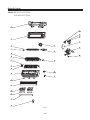


![CATHETER] l4](http://vs1.manualzilla.com/store/data/005800484_1-96ddef239138aa0bf6f1f198133819de-150x150.png)