1
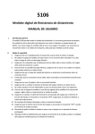
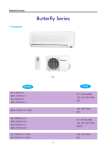
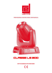
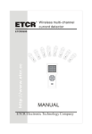
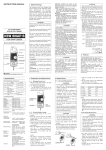
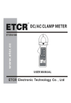
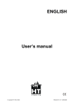
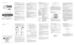
2) Measurement of Earth Voltage
Be sure to set the range selector to the 600VAC ,
and confirm the voltage is lower than 10 V . If the
voltage is higher than 10 V , power off the earth
electrode under test to drop the earth voltage
before you test again .
3) Measurement of Earth Resistance
Start from 2000 Ω , press the “Test/Stop” button ,
the “OK” indicator on the LCD will turns on ,
indicating the test is in process . In case of the
value displayed is too small, switch to 200 Ω or 20Ω
for measurement . The value displayed now is the
value of the earth resistance.
Notice:
The measurement current is approx. 2mA.
Therefore, even if a RCD is connected, the RCD
will not act.
The real earth resistance RX must be
calculated with the formula below:
RX=Re-re
Re: reading of instrument
re: earth resistance of common earth terminal of
commercial power system
Contents
Page
I. General Introduction … … … … … … … … … … … … … …2
II. Safety Rules… … … … … … … … … … … … … … … … … …2
III. Features … … … … … … … … … … … … … … … … … … …3
IV. Electrical Specification … … … … … … … … … … … … …4
V. Front Panel … … … … … … … … … … … … … … … … … …5
VI. Operation Instruction … … … … … … … … … … … … … …6
VII. Maintenance… … … … … … … … … … … … … … … … …13
VIII. Accessories… … … … … … … … … … … … … … … … …13
Warning
This user manual includes
warning and safety specifications,
which shall be strictly followed to
ensure safety. Please be sure to read
through this user manual before
operating this instrument.
12
1
9. LCD Size: (65x48)mm (digit height is 2 9 mm )
10. Power: 8x1.5V (R6P AA) batteries
11. Size: 190x155x75mm
12. Weight: approx. 900g(including batteries)
13. The instrument and accessories can be box for easy
carriage
14.Environment conditions
Operating temperature: 0℃~40℃
Relative humidity<80%
Storage temperature: -10℃ ~50℃
Relative humidity<80%
IV. Electrical Specification
Accuracy: ( %reading+digit ) the warranty is one year
Environment temperature: 23℃±5℃
Relative humidity: <75%
1.
Insulation Resistance
Testing Voltage
250V/500V/1000V
Output voltage
90%-110% of the test voltage
Range
0.1 MW-20GW
Resolution
0.01MW
Accuracy
0.1 MW-200 MW ± (3%rdg +5dgt)
5.
Earth Resistance Test
Normal Earth Resistance Test(3 wires method)
Danger: up to 50V voltage is generated between E - C
terminals when you test the earth resistance ! Do not
touch the test wire or you will get shocked.
Remember to confirm that the plug of the test wire has
been inserted into the test socket completely before you
start the test. Too loose connection brings errors for the
test result.
a.
Connection of Test Wire
Put the auxiliary earth spikes P1 and C1 into the soil
5 to 10 meters away from the object under test in straight
distance as shown in Fig 1, connect the green wire to
the terminal “E ” of the instrument , yellow wire to the
terminal “P ” and red wire to the terminal “C ” .
Notice: Be sure to insert the auxiliary earth spikes into soil
with high water content. In case of the soil is dry, has
many sands or gravels , be sure to add water to
ensure the soils in which auxiliary earth spikes are
inserted are wet . In case of cement land, place the
auxiliary earth spikes horizontally and add water, place
wet towels wrapping the auxiliary earth spikes before you
test.
200 MW-20GW ± (5%rdg +10dgt)
2.
-0.00
Earth Resistance
Range
Accuracy
Resolution
20W
± 2%rdg +0.1W
0.01W
200W
± (2%rdg +3dgt)
0.1W
2000W
Test Frequence
Approx. 820Hz
1W
3.
AC Voltage ( Earth Voltage ) Measurement
Measurement range: 1-600VAC
Accuracy: ( 2% rdg+5dgt )
Resolution:1V
4
H
Fig. 1
E is connected to the port of earth electrode
P is connected to the port of potential electrode
C is connected to the port of current electrode
9
I. General Introduction
The brand 5500 multi-functional instrument can
measure earth resistance, insulation resistance, AC
voltage and phase sequence. As a new generation
electrical measurement instrument which we have
successfully developed recently , It is aimed by the nice
and fashionable design, more stronger functions ,
easier to use and more reliable . The instrument and
accessories are all in the toolbox , suitable for field
application . It can be used to test the insulation
resistance and earth resistance of power system ,
electrical equipment , lightning arrester equipment , and
measure AC voltage and phase sequence test .
II. Safety Rules
1.
Be sure to read this user manual carefully before
using this instrument.
2.
Do not use this instrument when the rear cover is not
in place, otherwise you may get electrical shock.
3.
Be sure to check the insulation layer of the probe is
good and free of any damage before using this instrument.
4.
To prevent electrical shock, be sure not to touch
electric lead and circuit when the test is in process.
5.
Be sure to confirm the range selector has been set in
the appropriate range before testing.
6.
Confirm the plug of the wire has been tightly inserted
in the terminal.
7.
Be sure not to use the instrument when it is moist.
8.
Be sure not to turn the function selector when the
test is in process.
d.
Measurement of Earth Resistance
Rotatory selector set to 2000Ω press the “Test/Stop”
button , if the displayed value is too small , switch to
200Ω or 20Ω. The value displayed now is the resistance
of the earth resistor.
Notice: Be sure that no wire twists with any other wire.
Twisted or not well connected wires generate induction in
testing and impact readings. If the auxiliary earth
resistance is too big, some errors are generated. Be sure
that auxiliary earth spikes are inserted into moist soils, to
ensure the various parts are in full contact.
Transformer
Secondary side
-0.00
Primary side
H
Earth electrode
2-Wires Simplified Earth Resistance Test Method
This test method is intended for the application where
cann’t inserting an auxiliary earth spikes . In this method,
an existing earth electrode with very little earth
impedance is used , such as a metal water pipe , a
common earth of a commercial electric power system ,
or a earth terminal of a building , instead of the
auxiliary earth spikes “ C ” and “ P ” .
1)
Connection of Test Wire
Connect wires with simplified test wires as shown in the
figure above.
Danger: be careful of electrical shock when you use the
commercial electronic system earth method . Do not use
this instrument to test the voltage of power supply .
2
11
b. Operating Power and Wire Connection Test
Press the “Test/Stop” button , If the “Ok”indicato on
the LCD is light , it indicates that the wires are well
connected to “ P ” and “ C ” terminals , and the earth
resistance of the auxiliary earth spikes is within the
allowed range. If the “OK” indicator on the LCD is not light,
check the wires connected with “ P ” and “ C ” terminals or
reduce the auxiliary earth resistance to an appropriate
level by changing the position of earth-spikes or wetting
the soil. You can short circuit the clamps in red and
yellow wire terminals to check if they are broken .
c. Measurement of Earth Voltage
First the range selector set to the 600VAC first , and
confirm this voltage is lower than 10 V . If the voltage
is higher than 1 0 V , there will be error in the
measurement value of the earth resistance . In such
case, power off the earth electrode under test to reduce
the earth voltage before you test again.
9.
Do not apply any voltage higher than 600V AC or DC
between test terminals.
10. Do not test in inflammable environment since spark
may lead to explosion.
11. Stop using the instrument in case of any metal is
exposed caused by the shell or test wire is broken when
the test is in process.
12. Be sure that the test wire has been removed from the
test terminal and the function range selector in the “OFF”
position when you remove the rear cover to replace
battery.
13. Do not replace battery when the instrument is moist.
14. Be sure to set the function range selector at the
“OFF” position when your work is over.
15. Remember to remove the battery when you are not
going to use the instrument for a long period of time.
16. Replace battery immediately to ensure the
accuracy of measurement when the instrument displays
“
”.
-0.00
H
Fig. 2
E is connected to the port of earth electrode
P is connected to the port of potential electrode
C is connected to the port of current electrode
ACV is connected to the port of voltage electrode
10
III. Features
1.
Low power consuming CMOS dual integral A/D
conversion IC, automatic zero
2.
LCD: 3 1/2 display, maximum reading 1999
3.
Data holding function
4.
Measure voltage lower than AC600V
5.
Low Battery indication
6.
LCD back-light function
7.
Phase sequence test
8.
Automatic range ( Insulation test only )
3
VI. Operation Instruction
1.
Safety Precautions
Be sure to confirm the high voltage on the object
①
under test has been discharged , be careful of the high
voltage shock after the insulation resistance test is over.
②
Do not touch the object under test when the test is in
process otherise you should get electrical shock.
③
The object under test shall not be live and be sure to
confirm the object under test is securely earthed when
you test the insulation resistance . Short the two test
terminals of the object under test to discharge before
you start the test .
④
Do not lead any external voltage into the test loop
when you test the insulation resistance.
⑤
Be sure to confirm the selector is in right position and
the test wire is firmly connected before you start the test.
⑥
Up to 1000V high voltage is generated between “ L ”
terminal and “ E ” terminal when the high voltage button
has been pressed. Be sure not to touch any exposed part
of instrument and the object under test, otherwise you may
get electrical hazard.
2.
Battery Voltage Inspection
Turn on the instrument, if LCD does not display“
”
icon , it indicates the battery is good. If LCD displays
” icon , replace the batteries as
nothing or display “
described in the user manual .
3.
AC Voltage measurement
①
Do not test any voltage higher than 600V.
②
Connection Test Terminals.
Insert the red test lead into the “ ACV”socket of the
instrument and the black test lead into the “G” socket of the
instrument.
③
Set the rotary selector at the “600V”position and
connect the probe to the object under test.
④
The value displayed by the instrument now is the AC
voltage between two terminals of the object under test .
6
VI. Operation Instruction
1.
Safety Precautions
①
Be sure to confirm the high voltage on the object
under test has been discharged , be careful of the high
voltage shock after the insulation resistance test is over.
②
Do not touch the object under test when the test is in
process otherise you should get electrical shock.
③
The object under test shall not be live and be sure to
confirm the object under test is securely earthed when
you test the insulation resistance . Short the two test
terminals of the object under test to discharge before
you start the test .
④
Do not lead any external voltage into the test loop
when you test the insulation resistance.
⑤
Be sure to confirm the selector is in right position and
the test wire is firmly connected before you start the test.
⑥
Up to 1000V high voltage is generated between “ L ”
terminal and “ E ” terminal when the high voltage button
has been pressed. Be sure not to touch any exposed part
of instrument and the object under test, otherwise you may
get electrical hazard.
2.
Battery Voltage Inspection
Turn on the instrument, if LCD does not display“
”
icon , it indicates the battery is good. If LCD displays
” icon , replace the batteries as
nothing or display “
described in the user manual .
3.
AC Voltage measurement
①
Do not test any voltage higher than 600V.
②
Connection Test Terminals.
Insert the red test lead into the “ ACV”socket of the
instrument and the black test lead into the “G” socket of the
instrument.
③
Set the rotary selector at the “600V”position and
connect the probe to the object under test.
④
The value displayed by the instrument now is the AC
voltage between two terminals of the object under test .
6
3.
Insulation Resistance measurement
①
Connection of Test Terminals
Insert the red test lead into the “ L ” socket of the
instrument and the plug of the black test lead with flat
crocodile clamp into the “ E ” socket of the instrument .
②
Test connection
The wiring of “ E ” socket of the instrument is the earth wire ;
The wiring of “ L ” socket of the instrument is the line wire.
The “ G ” terminal socket of the instrument is the shield wire
to test the high insulation resistance.
If necessary insert another black wire with small crocodile
clamp into the “ G ” socket, The clamp connect to earth wire
to eliminate the measurement error caused by the leak
current in the surface of the product, and ensure the
accuracy of the test and reading stability.
Test Voltage selection
③
Select the test voltage you need to measure the insulation
resistance by turning the selector to the relevant voltage
class.
④
Test Operation
Connect the other terminal of the wire to the object
under test . Press the “ Test / Stop ” button , the red LED
indicator turns on , indicating the high voltage generated.
When the test has started, the LCD of the instrument
displays some readings. The value displayed by LCD is the
insulation resistance of the object under test.
If load Rx is great than maximun range 20GΩ, the LCD will
display “1”.
⑤
Turn off
When the test is over , press the “ Test / Stop ” button, the
red indicator turns off , indicating the test high voltage
has been disappeared . set the selector at “ OFF ”
position, LCD displays nothing. For capacitive
7
load, be sure to discharge the residual charges in the
object under test before you remove the test wire .
4.
Phase Sequence Measurement Method
There is high voltage in the 3 - phase wire . It would be
highly dangerous to touch, therefore be sure to handle with
care when you connect wires for a 3-phase measurement.
In case of the instrument indicator is not light when the test
wire has been connected but one phase may be live, Be
careful not to get shocked. Do not test any voltage is great
than 4 5 0 V / 5 0 - 6 0 Hz ( 3 - phase AC ) . Do not measure for
more than 30 minutes when the voltage is greater than
200V and not more than 3 minutes when the voltage is
great than 450V.
①
The phase sequence function allows you to test the
phase sequence of 3-phase AC power supply (100V450V/50-60Hz). When you have connected the phase
sequence probes with the test wires by input terminals ,
you can judge the positive phase and reverse phase of
3 - phase AC according to LED indicator and beep, also
phase missing indicated by LED .
②
Test State
Phase Sequence Test Indication
Open Phase Test Indication
Beep
Positive phase (CW indicator is on)
L1, L2 and L3 indicators are on.
Long beep
Reverse phase (CCW indicator is on)
L1, L2 and L3 indicators are on.
No beep
Missing phase (CCW indicator is on)
Any of L1, L2 and L3 is not on
No beep
Note: When the measurement probes have been
connected, the phase sequence measurement function
will indicate the positive phases and reverse phases of a 3phase AC, also the LED indicator will indicate the phase
missing. Be sure to measure with 3 triple-color test wires
with 3 round crocodile clamps .
Test frequency: 40-400Hz
4.
Phase Sequence Test
Phase-phase voltage range : 100V-450V
Frequency : 50-60Hz
5. Phase Sequence test result is indicated by LED, No
display in LCD
V. Front Panel
1
4
5
6
7
14
13
12
8
11
1.
2.
3.
4.
5.
6.
7.
8.
9.
10.
11.
12.
13.
14.
10
9
LCD
Phase sequence measurement LED indicators (CW,
CCW, L1, L2 and L3)
Insulation resistance measurement high voltage LED
indicator
Earth resistance measurement LED indicator
Data holding button
Test button
Back-light button
Function rotatory selector
“E/G” Earth resistance “E” input terminal
ACV measurement COM terminal
insulation “G” input terminal for shield
Earth resistance “P” input socket
Insulation “E” input socket
“C/L1 / L ” earth resistance “C ” input terminal
/ phase sequence “L1” input terminal / Insulation
“L” input terminal
“L 2 ”phase sequence input socket
“ACV” Input socket / Phase sequence “L 3 ” input
socket
5
load, be sure to discharge the residual charges in the
object under test before you remove the test wire .
4.
Phase Sequence Measurement Method
There is high voltage in the 3 - phase wire . It would be
highly dangerous to touch, therefore be sure to handle with
care when you connect wires for a 3-phase measurement.
In case of the instrument indicator is not light when the test
wire has been connected but one phase may be live, Be
careful not to get shocked. Do not test any voltage is great
than 4 5 0 V / 5 0 - 6 0 Hz ( 3 - phase AC ) . Do not measure for
more than 30 minutes when the voltage is greater than
200V and not more than 3 minutes when the voltage is
great than 450V.
①
The phase sequence function allows you to test the
phase sequence of 3-phase AC power supply (100V450V/50-60Hz). When you have connected the phase
sequence probes with the test wires by input terminals ,
you can judge the positive phase and reverse phase of
3 - phase AC according to LED indicator and beep, also
phase missing indicated by LED .
Test State
Phase Sequence Test Indication
Open Phase Test Indication
Beep
Long beep
Positive phase (CW indicator is on)
L1, L2 and L3 indicators are on.
Reverse phase (CCW indicator is on)
L1, L2 and L3 indicators are on.
No beep
Missing phase (CCW indicator is on)
Any of L1, L2 and L3 is not on
No beep
Note: When the measurement probes have been
connected, the phase sequence measurement function
will indicate the positive phases and reverse phases of a 3phase AC, also the LED indicator will indicate the phase
missing. Be sure to measure with 3 triple-color test wires
with 3 round crocodile clamps .
8
3
PHASE
8
②
2
Test frequency: 40-400Hz
4.
Phase Sequence Test
Phase-phase voltage range : 100V-450V
Frequency : 50-60Hz
5. Phase Sequence test result is indicated by LED, No
display in LCD
V. Front Panel
1
2
PHASE
3
4
5
6
7
14
13
12
8
11
1.
2.
3.
4.
5.
6.
7.
8.
9.
10.
11.
12.
13.
14.
10
9
LCD
Phase sequence measurement LED indicators (CW,
CCW, L1, L2 and L3)
Insulation resistance measurement high voltage LED
indicator
Earth resistance measurement LED indicator
Data holding button
Test button
Back-light button
Function rotatory selector
“E/G” Earth resistance “E” input terminal
ACV measurement COM terminal
insulation “G” input terminal for shield
Earth resistance “P” input socket
Insulation “E” input socket
“C/L1 / L ” earth resistance “C ” input terminal
/ phase sequence “L1” input terminal / Insulation
“L” input terminal
“L 2 ”phase sequence input socket
“ACV” Input socket / Phase sequence “L 3 ” input
socket
5
5500
Digital Multi Function Tester
OPERATION MANUAL
4 IN 1:
Insulation Resistance Measurement
Earth Resistance Measurement
ACV Measurement
Phase Sequence Test
Rev2 . 0
5500
Digital Multi Function Tester
OPERATION MANUAL
4 IN 1:
Insulation Resistance Measurement
Earth Resistance Measurement
ACV Measurement
Phase Sequence Test
Rev2 . 0
VII. Maintenance
This instrument is a precision electronic instrument, be
sure to maintain it well.
1.
Do not apply the instrument to any AC voltage higher
than 600V.
2.
To replace battery, remove the probe and power off
the instrument first. Unscrew the screws of the battery
cover and remove the battery cover. Be sure to replace the
battery according to the specification requirement.
3.
Do not forget to remove the battery if you are not
going to use the instrument for a long period of time .
Place the instrument at a dry and well ventilated
environment.
4.
Do not change any internal circuit of this instrument.
.
VIII. Accessories
1.
One copy of user manual.
2.
1 toolbox.
3.
4 sets of special test wires (a phase sequence test
wire, an insulation resistance test wire , an earth
resistance test wire , and a simplified test wire for
earth resistance )
4.
1.5V(R6P) AA batteries
8PCS
13
VII. Maintenance
This instrument is a precision electronic instrument, be
sure to maintain it well.
1.
Do not apply the instrument to any AC voltage higher
than 600V.
To replace battery, remove the probe and power off
2.
the instrument first. Unscrew the screws of the battery
cover and remove the battery cover. Be sure to replace the
battery according to the specification requirement.
Do not forget to remove the battery if you are not
3.
going to use the instrument for a long period of time .
Place the instrument at a dry and well ventilated
environment.
Do not change any internal circuit of this instrument.
4.
.
VIII. Accessories
1.
One copy of user manual.
2.
1 toolbox.
3.
4 sets of special test wires (a phase sequence test
wire, an insulation resistance test wire , an earth
resistance test wire , and a simplified test wire for
earth resistance )
1.5V(R6P) AA batteries
4.
8PCS
13