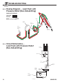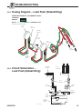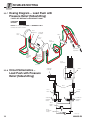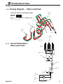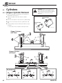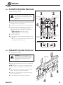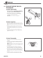
1
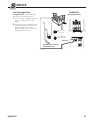
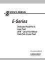
S ERVICE MANUAL E-Series Dedicated Push/Pull & Load Push QFM TM Quick Fork Mount Push/Pull & Load Push Manual Number 686455-R3 cascade corporation Cascade is a Registered Trademark of Cascade Corporation C ONTENTS Page INTRODUCTION, Section 1 Introduction Special Definitions PERIODIC MAINTENANCE, Section 2 Dedicated Push/Pulls 100 Hour Maintenance 500 Hour Maintenance 1000 Hour Maintenance 2000 Hour Maintenance QFMTM Push/Pulls 100 Hour Maintenance 500 Hour Maintenance 1000 Hour Maintenance TROUBLESHOOTING, Section 3 General Procedures Truck System Requirements Tool Requirements Troubleshooting Chart Push/Pull Plumbing Push/Pull (Non-Sideshifting) Push/Pull (Sideshifting) Push/Pull (Sideshifting with Solenoid) Push/Pull (Solenoid Sideshift and Hydraulically Positioned Platens) Wide Push/Pull Load Push Plumbing Load Push (Non-Sideshifting) Load Push with Pressure Relief (Non-Sideshifting) Load Push (Sideshifting) Load Push with Pressure Relief (Sideshifting) Wide Load Push Sheet SavTM Plumbing Sheet SavTM with Solenoids Hydraulic Sheet SavTM Push/Pull Circuit Push Function Pull Function Sideshift Circuit Hydraulically Positioned Circuit Electrical Circuit SERVICE, Section 4 Attachment Removal Dedicated Push/Pull QFMTM Push/Pull Faceplate and Arm Mechanism Faceplate Removal Gripper Assembly Removal Arm Mechanism Disassembly Frame and Faceplate Bearing Service Arm and Faceplate Bushing Service Gripper Bar Bearing Strip Service i 1 1 2 2 2 2 3 4 4 4 4 5 5 5 5 6 6 7 8 10 12 13 13 14 15 16 17 18 18 20 22 22 23 24 25 26 Page SERVICE, Section 4 (continued) Valve Push/Pull Valve Removal - Three Cartridges Push/Pull Valve Removal - One Cartridge Valve Service Load Push/Pull Valve Sequence Adjustment Cylinders Gripper Cylinder Removal Push/Pull Cylinder Removal Sideshift Cylinder Removal Hydraulically Positioned Platen Cylinder Removal Sheet-SavTM Cylinder Removal General Cylinder Service Procedures Push/Pull Cylinder Service Gripper Cylinder Service Hydraulically Positioned Platen Cylinder Service Sideshift Cylinder Service Sheet-SavTM Cylinder Service Push/Pull Cylinder Bushing Service Bearings Bearing Lubrication Bearing Service Hydraulic Faceplate Stop Adjustment Stop Valve Service Platens Platen Width Adjustment Platen Tip Adjustment Solenoid Valve Solenoid Valve Service SPECIFICATIONS, Section 5 Specifications Hydraulics Truck Carriage Auxiliary – Dedicated Push/Pulls Auxiliary – QFMTM Push/Pulls Torque Values 34 34 35 36 40 42 42 43 43 44 44 45 46 47 48 49 50 51 52 52 52 53 53 53 54 54 54 55 55 56 56 56 57 57 58 27 27 28 29 29 29 30 32 33 33 686455-R3 I 1.1 NTRODUCTION Introduction This manual provides the Periodic Maintenance, Troubleshooting, Service and Specifications for Cascade E-Series QFMTM and Dedicated Push/Pulls. In any communication about the attachment, refer to the product catalog and serial numbers stamped on the nameplate as shown. If the nameplate is missing, the numbers can be found stamped on the right front web of the baseplate. IMPORTANT: All hoses, tubes and fittings on these attachments are JIC. NOTE: Specifications are shown in both US and (metric) units. All fasteners have a torque value range of ±10% of stated value. 35E-PPS-A001 PTL 604920-1R0 PP1493.eps 1 00 A S 0 -1R -PP E 0 35 92 04 6 PTL 1.2 Nameplate Special Definitions The statements shown appear throughout this Manual where special emphasis is required. Read all WARNINGS and CAUTIONS before proceeding with any work. Statements labeled IMPORTANT and NOTE are provided as additional information of special significance or to make the job easier. WARNING - A statement preceded by WARNING is information that should be acted upon to prevent bodily injury. A WARNING is always inside a ruled box. CAUTION - A statement preceded by CAUTION is information that should be acted upon to prevent machine damage. IMPORTANT - A statement preceded by IMPORTANT is information that possesses special significance. NOTE - A statement preceded by NOTE is information that is handy to know and may make the job easier. 686455-R3 1 P 2.1 ERIODIC MAINTENANCE Dedicated Push/Pulls WARNING: After completing maintenance procedures, always test the attachment through five complete cycles. First test the attachment empty, then test with a load to make sure the attachment operates correctly before returning it to the job. CAUTION: For push/pulls used in extreme conditions, refer to TB 297 in place of this periodic maintenance. Failure to follow this schedule may result in push/pull failure and void warranty. 2.1-1 100-Hour Maintenance Every time the lift truck is serviced or every 100 hours of truck operation, whichever comes first, complete the following maintenance on the attachment: Frame Faceplate Push/Pull Cylinders • Check for loose or missing bolts, worn or damaged hoses and hydraulic leaks. NOTE: Nylon protection sleeves are available to prevent hoses from rubbing (Cascade part number 6086044 and 6088062). • Inspect faceplate and frame sliding bearing blocks for lubrication. Lubricate as necessary with Dubois FGG-2 Gripper food industry grease (Cascade Part No. 669306). Cylinders 2.1-2 500-Hour Maintenance After each 500 hours of truck operation, in addition to the 100-hour maintenance, perform the following procedures. • Inspect all mechanism pivot point bushings and pins for excessive wear and replace as necessary. See the service section of this manual. • Tighten the mechanism pivot pin retainer capscrews to 10 ft.-lbs. (13 Nm). • Tighten the gripper assembly capscrews to 120 ft.-lbs. (165 Nm) • Tighten the platen hook capscrews to 120 ft.-lbs. (165 Nm). WARNING: Platen capscrews must be tightened regularly to prevent equipment damage or personnel injury. • Check the clearance between the lower mounting hooks and the truck carriage bar: PP0665.eps Platens Linkage Mechanism Gripper Jaw Gripper Bar Faceplate Bearing Blocks Mechanism Pivot Pins, Bushings Frame Bearing Blocks Cylinder Pivot Pins, Retainers Gripper Assembly Capscrews Accumulator Quick-Change Hooks – 3/16 in. (5 mm) maximum. Bolt-on Hooks – Tight against lower carriage bar if non-sideshifting or 3/16 in. (5 mm) maximum if sideshifting. • If hook adjustment is necessary, refer Section 4.1-1, Step 6. Tighten the lower hook mounting capscrews to 120 ft.-lbs. (165 Nm). 2.1-3 Platen Retainers 1000-Hour Maintenance After each 1000 hours of truck operation, in addition to the 100 and 500-hour maintenance, perform the following procedures. • Check accumulator pre-charge and adjust to truck relief pressure if required. Use Charging Kit 228235 and refer to Accumulator User Guide 227196 for procedures. 2 Lower Mounting Hook Capscrews PP0662.eps Platen Hook Capscrews 686455-R3 P 2.1-4 ERIODIC MAINTENANCE 2000-Hour Maintenance After 2000 hours of truck operation, in addition to the 100, 500 and 1000-hour maintenance, forks in use shall be inspected at intervals of not more than 12 months (for single shift operations) or whenever any defect or permanent deformation is detected. Severe applications will require more frequent inspection. Fork inspection shall be carried out by trained personnel to detect any damage that might impair safe use. Any fork that is defective shall be removed from service. Reference ANSI B56.1-2005. Inspect for the following defects: • Surface cracks • Straightness of blade and shank • Fork angle • Difference in height of fork tips • Positioning lock • Wear on fork blade and shank • Wear on fork hooks • Legibility of marking NOTE: Fork Safety Kit 3014162 contains wear calipers, inspection sheets and safety poster. Also available is fork hook & carriage wear gauge 209560 (Class II), 209561 (Class III) and 6104118 (Class IV). 686455-R3 3 P ERIODIC MAINTENANCE 2.2 QFM Push/Pulls 2.2-1 100-Hour Maintenance TM WARNING: After completing maintenance procedures, always test the attachment through five complete cycles. First test the attachment empty, then test with a load to make sure the attachment operates correctly before returning it to the job. Every time the lift truck is serviced or every 100 hours of truck operation, whichever comes first, complete the following maintenance on the attachment: • Check for loose or missing bolts, worn or damaged hoses and hydraulic leaks. Faceplate Push/Pull Cylinders • Inspect faceplate and frame sliding bearing blocks for lubrication. Lubricate as necessary with Dubois FGG-2 food industry grease (Cascade Part No. 669306). 2.2-2 Frame 500-Hour Maintenance After each 500 hours of truck operation, in addition to the 100-hour maintenance, perform the following procedures. Gripper Cylinders • Inspect all mechanism pivot point bushings and pins for excessive wear and replace as necessary. See the service section of this manual. • Tighten the mechanism pivot pin retainer capscrews to 10 ft.-lbs. (13 Nm). • Tighten the gripper assembly capscrews to 120 ft.-lbs. (165 Nm) • Tighten the platen mounting capscrews to 40 ft.-lbs. (60 Nm). PP0892.eps Gripper Bar WARNING: Platen capscrews must be tightened regularly to prevent equipment damage or personnel injury. • Check for .125 in. (3.2 mm) maximum clearance between lower mounting hooks and truck carriage bar. Refer to Step 5 in this manual if adjustment is necessary. • Check for .06 in. (1.6 mm) maximum clearance between upper hook setscrews and truck carriage bar. Refer to Section 4.1-2, Step 6 in this manual if adjustment is necessary. Faceplate Roller Bearings Mechanism Pivot Pins, Bushings Frame Roller Bearings Cylinder Pivot Pins, Retainers Accumulator • Tighten lower hook capscrews to 60 ft.-lbs. (80 Nm). 2.2-3 Linkage Mechanism Gripper Jaw Platens 1000-Hour Maintenance After each 1000 hours of truck operation, in addition to the 100 and 500-hour maintenance, perform the following procedures. • Check accumulator pre-charge and adjust to truck relief pressure if required. Use Charging Kit 228235 and refer to Accumulator User Guide 227196 for procedures. Upper Hook Setscrews Platen Mounting Capscrews 4 PP0895.eps Lower Mounting Hook Capscrews 686455-R3 T 3.1 ROUBLESHOOTING General Procedures 3.1-1 Truck System Requirements • Truck hydraulic pressure should be within the range shown in Specifications, Section 5.1. PRESSURE TO THE ATTACHMENT MUST NOT EXCEED 2300 PSI (160 BAR). • Hydraulic flow should be within volume range as shown in Specifications, Section 5.1. • Hydraulic fluid supplied to the attachment must meet the requirement shown in Specifications, Section 5.1. 3.1-2 WARNING: Before servicing any hydraulic component, relieve pressure in the system. Turn the truck off and move the truck auxiliary control valves several times in both directions. After completing any service procedure, test the attachment through several cycles. First test the attachment empty to bleed any air trapped in the system to the truck tank. Then test the attachment with a load to be sure it operates correctly before returning to the job. Stay clear of the load while testing. Do not raise the load more than 4 in. (10 cm) off the floor while testing. Tools Required In addition to a normal selection of hand tools, the following will be required: • Inline Flow Meter Kit: Flow Meter Kit 671477 20 GPM (75 L/min.) – Cascade Part No. 671477 • Pressure Gauge Kit: 5000 psi (345 bar) – Cascade Part No. 671212 3.13 (2) No. 8-12 JIC/ O-ring Flow Meter Troubleshooting Chart GA0013.eps (2) No. 6-8 JIC Reducer Determine All The Facts – It is important that all the facts regarding the problem are gathered before beginning service procedures. The first step is to talk to the equipment operator. Ask for a complete description of the malfunction. The following guidelines can then be used as a starting point to begin troubleshooting procedures: Push/Pull Circuit • Attachment will not pull the load. • Faceplate will not extend or retract. • Faceplate operates slowly. • Gripper bar will not lower or raise. • Gripper bar is not sequenced with push/pull function. • Gripper bar will not hold the slip sheet when pulling load onto platens. To correct one of these problems, see Section 3.3. Pressure Gauge Kit 671212 Pressure Gauge No. 6 and No. 8 JIC Swivel Tee No. 6-6 Hose GA0014.eps No. 4-6 Pipe/JIC No. 6-8 JIC Reducer No. 6 JIC/ O-Ring ▲ ▲ Not included in Pressure Gauge Kit 671212 Sideshift Circuit • Attachment will not sideshift. • Attachment sideshifts slowly. To correct this problem, see Section 3.4. Hydraulically Positioned Platen Circuit • Attachment will not position platens. To correct this problem, see Section 3.5. 686455-R3 5 T 3.2 3.2-1 ROUBLESHOOTING Push/Pull Plumbing Hosing Diagram – Push/Pull (Non-Sideshifting) GR GB PB Hose Reel PR Gripper Cylinders Hose Terminal Truck Auxiliary Valve Push/Pull Cylinders Valve FACEPLATE RETRACT PRESSURE RETURN PP0409.eps 3.2-2 NOTE: For faceplate EXTEND reverse the colors shown. Circuit Schematics – Push/Pull (Non-Sideshifting) Push/Pull Cylinders Gripper Cylinders PR RET GB GR PB EXT PR Valve with three cartridges RET GB GR PB EXT Valve with one cartridge Hose Terminal Hose Reel Truck Relief Valve Truck Auxiliary Valve Truck Hydraulic Pump 6 PP1495.eps 686455-R3 T 3.2-3 ROUBLESHOOTING Hosing Diagram – Push/Pull (Sideshifting) Hose Reel Hose Terminal Sideshift Cylinder GR GB Hose Reel PB Hose Terminal PR Gripper Cylinders Push/Pull Cylinders Valve Sideshift Auxiliary Valve Push/Pull Auxiliary Valve FACEPLATE RETRACT and SIDESHIFT RIGHT PRESSURE RETURN PP0363.eps 3.2-4 NOTE: For faceplate EXTEND and SIDESHIFT RIGHT, reverse the colors shown. Circuit Schematics – Push/Pull (Sideshifting) Push/Pull Cylinders Gripper Cylinders PR GB GR PB PR Sideshift Cylinder RET GB GR PB Valve with three cartridges RET EXT EXT Valve with one cartridge Hose Terminals Hose Reels Sideshift Auxiliary Valve 686455-R3 PP0364.eps Truck Relief Valve Push/Pull Auxiliary Valve Truck Hydraulic Pump 7 T 3.2-5 ROUBLESHOOTING Hosing Diagram – Push/Pull (Sideshift with Solenoid) FACEPLATE RETRACT PRESSURE RETURN NOTE: For faceplate EXTEND, reverse the colors shown. GR GB Valve Hose Reel Hose Terminal Truck Auxiliry Valve PB PR Gripper Cylinders Push/Pull Cylinders Solenoid Valve PP0365.eps SIDESHIFT RIGHT PRESSURE RETURN NOTE: For sideshift LEFT, reverse the colors shown. Hose Reel Hose Terminal Truck Auxiliary Valve Solenoid Valve PP0366.eps 8 Sideshift Cylinder 686455-R3 T 3.2-6 ROUBLESHOOTING Circuit Schematics – Push/Pull (Sideshift with Solenoid) Push/Pull Cylinders Gripper Cylinders PR Sideshift Cylinder RET GB GR PB EXT PR RET Valve with three cartridges GR GB PB EXT Valve with one cartridge Solenoid Valve Hose Terminal Truck Auxiliary Valve Hose Reel Truck Relief Valve Truck Hydraulic Pump PP0367.eps 686455-R3 9 T 3.2-7 ROUBLESHOOTING Hosing Diagram – Push/Pull (Solenoid Sideshift and Hydraulically Positioned Platens) FACEPLATE RETRACT AND POSITION PLATENS PRESSURE RETURN GR NOTE: For faceplate EXTEND, reverse the colors shown. Hose Reel Truck Auxiliary Valve GB Valve Hose Terminal PB PR Gripper Cylinders Push/Pull Cylinders PP0368.eps Solenoid Valves Additional Solenoid Valve (if equipped) Position Platen Cylinder SIDESHIFT RIGHT PRESSURE RETURN NOTE: For sideshift LEFT, reverse the colors shown. Hose Reel Hose Terminal Truck Auxiliary Valve Solenoid Valves PP0369.eps 10 Sideshift Cyclinder 686455-R3 T 3.2-8 ROUBLESHOOTING Circuit Schematic – Push/Pull (Solenoid Sideshift and Hydraulically Positioned Platens) Push/Pull Cylinders Gripper Cylinders Valve with three cartridges PR GB RET EXT PB GR Sideshift Cylinder PR EXT RET Hydraulic Positioned Platen Cylinder RET RET GR GB PB EXT Valve with one cartridge Additional Solenoid Valve (if equipped) Truck Relief Valve Solenoid Valves Hose Terminal Hose Reel Truck Auxiliary Valve Truck Hydraulic Pump PP0370.eps 686455-R3 11 T 3.2-9 ROUBLESHOOTING Hosing Diagram – Wide Push/Pull Optional Third Cylinder FACEPLATE RETRACT PRESSURE RETURN NOTE: For faceplate EXTEND reverse the colors shown. GR Junction Block GB PB Hose Reel PR Gripper Cylinders Truck Auxiliary Valve Push/Pull Cylinders Valve Optional Third Cylinder PP0361.eps 3.2-10 Hose Terminal Circuit Schematics – Wide Push/Pull Push/Pull Cylinders Gripper Cylinders Units with Non-Solenoid Activated Sideshifting See Sideshift hosing and circuit schematics in Sections 4.2-3 and 4.2-4 Units with Solenoid Activated Sideshifting See Sideshift hosing and circuit schematics in Sections 4.2-5 and 4.2-6 PR PR GB GR GB PB PB RET RET GR Junction Block Valve with three cartridges EXT EXT Valve with one cartridge Truck Relief Valve Hose Terminal Truck Auxiliary Valve Hose Reel Truck Hydraulic Pump 12 PP0362.eps 686455-R3 T 3.3 3.3-1 ROUBLESHOOTING Load Push Plumbing Hosing Diagram – Load Push (Non-Sideshifting) FACEPLATE RETRACT PRESSURE RETURN NOTE: For faceplate EXTEND reverse the colors shown. Hose Reel Hose Terminal Truck Auxiliary Valve Push Cylinders PP0410.eps 3.3-2 Circuit Schematics – Load Push (Non-Sideshifting) Push Cylinders Hose Terminal Hose Reel Truck Relief Valve Truck Auxiliary Valve Truck Hydraulic Pump 686455-R3 PP0411.eps 13 T 3.3-3 ROUBLESHOOTING Hosing Diagram – Load Push with Pressure Relief (Non-Sideshifting) FACEPLATE RETRACT PRESSURE RETURN NOTE: For faceplate EXTEND reverse the colors shown. Valve Hose Reel Hose Terminal Truck Auxiliary Valve Push Cylinders PP0412.eps 3.3-4 Circuit Schematics – Load Push with Pressure Relief (Non-Sideshifting) Push Cylinders PB PR Valve Hose Terminal Hose Reel Truck Relief Valve Truck Auxiliary Valve Truck Hydraulic Pump 14 PP0413.eps 686455-R3 T 3.3-5 ROUBLESHOOTING Hosing Diagram – Load Push (Sideshifting) FACEPLATE RETRACT and SIDESHIFT RIGHT PRESSURE RETURN NOTE: For faceplate EXTEND and SIDESHIFT LEFT reverse the colors shown. Hose Reel Hose Terminal Sideshift Cylinder Hose Reel Hose Terminal Push Cylinders Truck Auxiliary Valves PP0416.eps 3.3-6 Circuit Schematics – Load Push (Sideshifting) Sideshift Cylinder Push Cylinders Hose Terminal Hose Reel Truck Relief Valve Hose Reel Truck Auxiliary Valves Truck Hydraulic Pump 686455-R3 PP0417.eps 15 T 3.3-7 ROUBLESHOOTING Hosing Diagram – Load Push with Pressure Relief (Sideshifting) FACEPLATE RETRACT and SIDESHIFT RIGHT PRESSURE RETURN NOTE: For faceplate EXTEND and SIDESHIFT LEFT reverse the colors shown. Hose Terminal Hose Reel Sideshift Cylinder Valve Hose Reel Hose Terminal Push/Pull Cylinders Sideshift Auxiliary Valve LoadPush Auxiliary Valve Push Cylinders PP0418.eps 3.3-8 Circuit Schematics – Load Push with Pressure Relief (Sideshifting) Sideshift Cylinder Valve Hose Terminal Hose Reel Hose Reel Sideshift Auxiliary Valves Load-Push Auxiliary Valves Truck Relief Valve Truck Hydraulic Pump PP0360.eps 16 686455-R3 T 3.3-9 ROUBLESHOOTING Hosing Diagram – Wide Load Push Optional Third Cylinder FACEPLATE RETRACT and SIDESHIFT RIGHT PRESSURE RETURN NOTE: For faceplate EXTEND and SIDESHIFT LEFT reverse the colors shown. Junction PB Block Hose Reel PR Truck Auxiliary Valve Valve Push Cylinders Optional Third Cylinder Hose Terminal PP0414.eps 3.3-10 Circuit Schematics – Wide Load Push Push Cylinders Junction Block Valve Hose Terminal Hose Reel Truck Relief Valve Truck Auxiliary Valve Truck Hydraulic Pump 686455-R3 PP0415.eps 17 T 3.4 3.4-1 ROUBLESHOOTING Sheet-SaveTM Plumbing Hosing Diagram – Sheet-SavTM with Solenoids FACEPLATE RETRACT GR PRESSURE RETURN Junction Block NOTE: For faceplate EXTEND reverse the colors shown. GB PB PR Gripper Cylinders NOTE: Units with Non-Solenoid activated sideshifter, see sideshift hosing and circuit schematics in Sections 4.2-3 and 4.2-4. Valve Push/Pull Cylinders Hose Reel Hose Terminal Truck Auxiliary Valve PP1496.eps Sheet-Sav Cylinder TM LB SHEET-SAVTM LIFT PRESSURE RETURN LR Valve NOTE: For Sheet-Sav STOMP reverse the colors shown. TM Sheet-SavTM Cylinder Hose Reel LB Truck Auxiliary Valve 18 Hose Terminal LR 686455-R3 T 3.4-2 ROUBLESHOOTING Circuit Schematics – Sheet-SavTM with Solenoids (Sideshifting) Gripper Cylinders Push/Pull Cylinders PR GB GR PB Junction Block GB/PR LB PB GR Independent Gripper Control Solenoid (Optional) LB LR LR Sheet-SavTM Cylinders Sheet-SavTM Solenoid EXT RET Sideshift Cylinder Valve Hose Terminals Hose Reel Sideshift Auxiliary Valve Hose Reel Truck Relief Valve Truck Hydraulic Pump 686455-R3 Sheet-SavTM & Push/Pull Auxiliary Valve PP0424.eps 19 T 3.4-3 ROUBLESHOOTING Hosing Diagram – Hydraulic Sheet-SavTM FACEPLATE RETRACT Junction Block PRESSURE RETURN NOTE: For faceplate EXTEND reverse the colors shown. PB PR Gripper Cylinders Push/Pull Cylinders Hose Reel Valve Stomp In Push/Pull Auxiliary Valve To SheetSavTM Auxiliary Valve Hose Terminal PP1586.eps SHEET-SAVTM LIFT PRESSURE RETURN NOTE: For Sheet-Sav STOMP reverse the colors shown. TM Valve Sheet-SavTM Cylinder Stomp In LB LR To Push/Pull Auxiliary Valve Hose Reel Sheet-SavTM Auxiliary Valve LB Hose Terminal LR LB LR Sheet-SavTM Cylinder 20 686455-R3 T 3.4-4 ROUBLESHOOTING Circuit Schematics – Hydraulic Sheet-SavTM Gripper Cylinders Push/Pull Cylinders PR GB GR PB Junction Block Sheet-SavTM Cylinders GB/PR LR LB GR PB PB GR Valve Stomp In Pull In Push In PP1513.eps Hose Terminals Hose Reel Sheet-SavTM Auxiliary Valve Truck Relief Valve 686455-R3 Push/Pull Auxiliary Valve Truck Hydraulic Pump 21 T 3.5 ROUBLESHOOTING Push/Pull Circuit There are seven potential problems that could affect push/pull operation. • Incorrect hydraulic pressure/volume from truck. • Physically jammed mechanism. • External leaks. • Worn or defective cylinder seals. • Valve assembly malfunction. • Kinked supply hoses. • Incorrect adjustment on gripper sequence control valves. WARNING: Before removing any hoses, relieve pressure in the hydraulic system. With the truck off, open the truck auxiliary control valve(s) several times in both directions. 1 Check the pressure delivered by the truck. Refer to the truck service manual. The pressure must be within 100 psi (7 bar) of specified truck pressure. TRUCK PRESSURE MUST NOT EXCEED 2300 PSI (160 BAR), measured at the truck carriage hose terminal. 2 Check the flow volume at the carriage hose terminal. See Section 5.1-1 for recommended flow volumes. If the truck pressure and flow are correct, proceed with troubleshooting. 3.5-1 Push Function Gripper bar will not raise – • Kinked hoses. • Physically jammed jaw assembly. • Valve out of sequence. Refer to Section 4.3-3. Gripper bar drifts down – • Valve's check valve cartridge is stuck in open position due to contamination or damaged seals. Refer to Section 4.3-3. • Damaged seal in gripper cylinder. Refer to Section 4.4-1. Gripper bar raises but faceplate does not extend – • Valve is out of sequence. Refer to Section 4.3-3. • Valve's relief cartridge is struck in closed position due to contamination or damaged seals. Refer to Section 4.4-1. Faceplate extends slowly – • Worn seal in push/pull or gripper cylinders. Refer to Section 4.4. 22 686455-R3 T 3.5-2 ROUBLESHOOTING Pull Function Faceplate retracts before gripper bar fully closes – • Gripper sequence valve requires adjustment. Refer to Section 4.3-3. • Check gripper hose size and length. Hoses must be Parker Twinline 550 H-5 (or equivalent), 41 in. (104 cm) long with No. 6 fittings. Gripper bar will not lower – • Physically jammed mechanism. • Valve's check valve cartridge is stuck in closed position due to contamination or damaged seals. Refer to Section 4.3-1 or 4.3-2. Gripper bar lowers but faceplate does not retract – • Valve's check valve cartridge is stuck in closed position due to contamination or damaged seals. Refer to Section 4.3-1 or 4.3-2. • Worn seals in the push/pull cylinders. Refer to Section 4.4. Gripper bar does not hold slipsheet during faceplate retract – • Damaged gripper pad or jaw. • Worn seals in gripper cylinders. Refer to Section 4.4. 686455-R3 23 T 3.6 ROUBLESHOOTING Sideshift Circuit There are seven potential problems that could affect sideshifting operation. • Insufficient hydraulic pressure/volume from the truck. • External leaks. • Faulty electrical connection (solenoid-equipped attachments). • Defective solenoid valve (solenoid equipped attachments). • Lower mounting hooks installed incorrectly. See Section 4.1-1 Step 2 or 4.1-2 Step 3. • Worn bearings. See Section 4.5-2. • Worn or defective cylinder seals. WARNING: Before removing any hoses, relieve pressure in the hydraulic system. With the truck off, open the truck auxiliary control valve(s) several times in both directions. 1 Check the pressure delivered by the truck. Refer to the truck service manual. The pressure must be within 100 psi (7 bar) of specified truck pressure. TRUCK PRESSURE MUST NOT EXCEED 2300 PSI (160 BAR), measured at the carriage hose terminal. 2 Check the flow volume at the carriage hose terminal. See Section 5.1-1 for recommended flow volumes. If the truck pressure and flow are correct, proceed with troubleshooting. 3 Solenoid equipped attachments – Press the control knob push/pull button. • If the solenoid valve 'clicks', it is working correctly. Continue the troubleshooting check list. 6 • If the solenoid valve does not 'click', the solenoid valve is faulty. Troubleshoot the electrical circuit as described in Section 3.8. • If the solenoid still does not 'click', the solenoid valve is faulty. Service the solenoid valve as described in Section 4.8-1. 4 Inspect the sideshift bearing blocks between the truck carriage and attachment frame for excessive wear. Replace if necessary. Refer to Section 4.5-2. 5 Sideshift completely to the left and hold the control handle in this position for 5 seconds. Check for external leaks at the cylinder, fittings and hoses. 6 Disconnect and plug the cylinder rod end hose or tube. Install a drain hose and place the hose end in a bucket. Start the truck. Actuate the control handle to pressure the base end of the cylinder for 5 seconds. • If there is oil flowing out of the rod end of the cylinder, the cylinder seals are defective and require service. Refer to section 4.4-3. PP0420.eps • If there is no oil flow out of the rod end of the cylinder, the problem is not hydraulic. 24 686455-R3 T 3.7 ROUBLESHOOTING Hydraulically Positioned Platen Circuit There are five potential problems that could affect sideshifting operation. • Insufficient hydraulic pressure/volume from the truck. • External leaks. • Faulty electrical connection (solenoid-equipped attachments). • Defective solenoid valve (solenoid equipped attachments). • Worn or defective cylinder seals. WARNING: Before removing any hoses, relieve pressure in the hydraulic system. With the truck off, open the truck auxiliary control valve(s) several times in both directions. 1 Check the pressure delivered by the truck. Refer to the truck service manual. The pressure must be within 100 psi (7 bar) of specified truck pressure. TRUCK PRESSURE MUST NOT EXCEED 2300 PSI (160 BAR), measured at the carriage hose terminal. 2 Check the flow volume at he carriage hose terminal. See Section 5.1-1 for recommended flow volumes. If the truck pressure and flow are correct, proceed with troubleshooting. 5 3 Press the control knob push/pull button. • If the solenoid valve 'clicks', it is working correctly. Continue the troubleshooting check list. • If the solenoid valve does not 'click', the solenoid valve is faulty. Troubleshoot the electrical circuit as described in Section 3.8. • If the solenoid still does not 'click', the solenoid valve is faulty. Service the solenoid valve as described in Section 4.8-1. 4 Extend faceplate. Positioned the platens outward and hold the control handle in this position for 5 seconds. Check for external leaks at the cylinder, fittings and hoses. 5 Disconnect and plug the cylinder rod side hose or tube. Install a drain hose and place the hose end in a bucket. Start the truck. Actuate the control handle to pressure the base end of the cylinder for 5 seconds. PP0421.eps • If there is oil flowing out of the rod side of the cylinder, the cylinder seals are defective and require service. Refer to section 4.4-4. • If there is no oil flow out of the rod side of the cylinder, the problem is not hydraulic. 686455-R3 25 T 3.8 ROUBLESHOOTING Electrical Circuit (Solenoid equipped attachments) See the wire diagrams and schematic shown. Use the proper schematic while following the steps below. 1 Check the control knob circuit fuse. Replace as Two Function (One Button Control Knob) 7.5 Amp Fuse White Knob Button Black necessary. 2 Check the solenoid coil to make sure it matches the truck voltage. The coil voltage is marked at the terminals. Verify by checking the resistance across the terminal with wired disconnected. Coil Voltage 12V 24V 36V 48V Diode 18 Gauge Wire 1/4 in. Terminals Ohms Resistance 2 14 36 44 Solenoid Valve • If there is no ohmmeter reading shown, the solenoid coil is defective and requires replacing. Refer to Section 4.8-1 3 Check for truck voltage at the solenoid coil terminals when the knob button is pushed. Diode 7.5 Amp Fuse White Black 4 Check for loose electrical connection at the truck ignition switch, control knob button(s), solenoid valve terminals and diodes. 5 Remove the diode(s) from the solenoid valve terminals. Test with an ohmmeter for high resistance in one direction and no resistance in the other direction. If there is no resistance in both directions, replace the diode. User Supplied Wire PP1041.eps Three Function (Two Button Control Knob) 7.5 Amp Fuse Green Black White Diode Green 7.5 Amp Fuse Black White Diodes User Supplied Wire Solenoid Valves PP1040.eps 26 686455-R3 S ERVICE 4.1 Attachment Removal 4.1-1 Dedicated Push/Pulls 1 Fully extend the faceplate. pallet. Lower the attachment onto a 2 Disconnect the lower hooks. 1 Bolt-On Hooks – Remove the lower mounting hooks. For reassembly, tighten the capscrews to a torque of 125 ft.-lbs. (170 Nm). Quick-Change Hooks – Pull out the retaining pins, slide the hooks down and reinstall the pins in the lower holes. For reassembly, slide the hooks up and install the pins in the top holes. WARNING: Before removing any hoses, relieve pressure in the hydraulic system. With the truck off, open the truck auxiliary control valve(s) several times in both directions. PP1498.eps 3 Disconnect, tag and plug the hoses at the carriage hose terminals. 4 Solenoid Equipped Attachments – Disconnect the electrical connection at the truck carriage. 3 5 Lower the truck carriage and back away from the attachment. 6 For installation, reverse the above procedures excepts the following items: • For complete installation procedures, refer to Installation Manual 684944. 3 PP1049.eps BOLT-ON HOOKS QUICK-CHANGE HOOKS Carriage Bar 2 RC0368.eps Carriage Bar ST JU AD LH Lower Hook 2 Guide RC0367.eps ® de a sc ca LH Lower Hook (Unlocked) Non-Sideshifting Units: Tight against lower carriage bar. GA0451.eps Lower Hook 686455-R3 Sideshifting Units: Clearance of 0.09–0.18 in. (2.5–5.0 mm). -1 14 55 67 C- Locking Pin 27 S 4.1-2 ERVICE QFM Push/Pulls 1 TM 1 Extend the faceplate. 2 Raise the platens 2 ft. (60 cm) off the floor. WARNING: Before removing any hoses, relieve pressure in the hydraulic system. With the truck off, open the truck auxiliary control valve(s) several times in both directions. 2 3 Disengage the hooks from the lower carriage bar. 4 Disconnect, tag and plug the hoses at the carriage hose PP1499.eps terminals. 5 Lower the attachment to the floor and back away. 6 For reassembly, reverse the above procedures excepts 3 the following items: • For complete installation procedures, refer to Installation Manual 684948. 4 5 PP1500.eps PP1043.eps 6 6 Engage lower hooks. Adjust Forks PP1515.eps PP0883.eps 28 Adjust clearance to 1/8 in. (3.2 mm) 686455-R3 S 4.2 4.2-1 ERVICE Faceplate and Arm Mechanism Faceplate Removal 1 Fully extend the faceplate. 3 1 WARNING: Before removing any hoses, relieve pressure in the hydraulic system. With the truck off, open the truck auxiliary control valve(s) several times in both directions. 2 Remove the gripper assembly from the faceplate as described in Section 4.2-2. 3 Attach an overhead hoist to the top of the faceplate and take up slack. 4 Remove the capscrews and eyepins from the inner secondary arm lower pivot pins. Remove the pivot pins. For reassembly, tighten the capscrew to a torque of 10 ft.-lbs. (13 Nm). 5 Remove the faceplate with the hoist. Tilt the faceplate to disengage the outer secondary arm bearings from the faceplate channels. Set the faceplate face down. PP1058.eps 4.2-2 4 2 Gripper Assembly Removal 1 Fully extend the faceplate. 1 WARNING: Before removing any hoses, relieve pressure in the hydraulic system. With the truck off, open the truck auxiliary control valve(s) several times in both directions. 2 2 Attach an overhead hoist to the gripper assembly lifting holes and take up slack. 3 Disconnect, tag and plug the hoses from the junction block. 4 Remove the hex capscrews fastening the gripper assembly to the faceplate. For reassembly, clean and dry capscrews. Apply Loctite 242 (blue) to capscrews and tighten to a torque of 125 ft.-lbs. (170 Nm). 5 For reassembly, reverse the above procedures. 3 PP1042.eps 686455-R3 4 29 S 4.2-3 ERVICE Arm Mechanism Disassembly WARNING: Before removing any hoses, relieve pressure in the hydraulic system. With the truck off, open the truck auxiliary control valve(s) several times in both directions. 1 Remove the faceplate from the arm mechanism as described in Section 4.2-1. 2 Remove the push/pull cylinders from the mechanism arms as described in Section 4.4-2. 3 Disconnect, plug and tag the four hoses from the valve. Remove the valve from the inner primary arm. For reassembly, tighten the capscrews to a torque of 15 ft.-lbs. (20 Nm). 4 Remove the bearing blocks/roller, pin, spacer tube and shims from the outer secondary arms. Note the location of the shims for reassembly. 5 Remove the capscrews and eyepins from the outer secondary arm pivot pins points. Remove the pivot pins to remove the arms. For reassembly clean and dry capscrews. Apply Loctite 242 (blue) to capscrews and tighten to a torque of 10 ft.-lbs. (13 Nm). 6 Remove the capscrew and eyepins or retainers form the R.H. Inner Secondary Arm upper pivot point. Drive out the pivot pin to remove the inner secondary arms. Note the location of the shims for reassembly. For reassembly clean and dry capscrews. Apply Loctite 242 (blue) to capscrews and tighten to a torque of: Eyepin Capscrews – 10 ft.-lbs. (13 Nm) Retainer Capscrews – 21 ft.-lbs. (28 Nm) 7 Attach a hoist to the inner primary arm. 8 Remove the capscrews and eyepins from the outer primary arm center pivot points. Remove the pivot pins. Raise the primary arms out through the top of the frame guides. 9 Remove the bearing blocks, pin, spacer tube and shims from the outer primary arms. Note the location of the shims for reassembly. 10 Remove the capscrews and eyepins from the inner primary arm lower pivot pins. Note the location of the shim for reassembly. Remove the pivot pins and lift away the arm. For reassembly clean and dry capscrews. Apply Loctite 242 (blue) to capscrews and tighten to a torque of 10 ft.-lbs. (13 Nm). 11 For reassembly, reverse the above procedures except as follows: • Apply waterproof chassis grease (Whitmore OmniTask EP2 NLGI grade 2) to the bearing blocks/ roller and faceplate and frame channels. 30 686455-R3 S ERVICE Current Models Pin 11 Roller Bearing Block (Early Models) 4 Retainer 7 Inner Primary Arms 11 9 3 Inner Secondary Arms Outer Secondary Arms 5 6 Eyepin Outer Primary Arms 10 5 PP2158.eps 8 686455-R3 31 S 4.2-4 ERVICE Frame and Faceplate Bearing Service 1 Extend the faceplate to the position shown. 2 Support the upper arm pivot pin using one of the following methods: • An overhead hoist hooked to the pin. • If an overhead hoist is unavailable, support the top pivot pin with a notched pipe (see pipe illustration), bottle jack and wood block placed on the platens. Notched Pipe 3 Remove the outer secondary arm lower pins. Tilt the faceplate forward to disengage the bearings from the channels. 4 Install new faceplate bearings and reinstall to the faceplate channels. Tilt the faceplate back to support while removing frame bearings. 5 Remove the outer primary arm middle pivot pins. Raise the arms out through the top of the frame channels. 12 in. (30 cm) 6 Install new frame bearings and reinstall to the frame channels. 7 Reinstall the pivot pins to the arms. Clean and dry capscrews. Apply Loctite 242 (blue) and tighten the retaining capscrews to a torque of 10 ft.-lbs. (13 Nm). Faceplate Bearings 3 2 PP0711.eps Frame Bearings 5 4 Faceplate 3 2 Platens PP0663.eps 32 686455-R3 S 4.2-5 ERVICE Arm and Faceplate Bushing Service 2 1 Remove the arms from the attachment as described in Section 4.2-3. Bushing Driver 2 Remove the bushings from the arms and faceplate using a bushing driver: • If you do not have a bushing driver, a tool can be fabricated for bushing removal. See the tool illustrated for bushing driver dimensions. 3 For reassembly, reverse the above procedures except PP0714.eps as follows: • Install new bushings using the bushing driver. CAUTION: The bushings may be damaged if installed without a bushing driver. 3.00 in. (75 mm) 2.16 in. (55 mm) 1.37 in. (35 mm) .59 in. (15 mm) 1.14 in. DIA. (29 mm) .94 in. DIA. (24 mm) 4.2-6 Gripper Bar Bearing Service PP0710.eps .55 in. DIA. (14 mm) .75 in. DIA. (19 mm) NOTE: Early production units are not equipped with gripper bar bearing strips. 1 Remove the gripper assembly from the faceplate as 3 described in Section 4.2-2. 2 Drive out the roll pins fastening the gripper bar to the gripper cylinder rods. 3 Remove the bearings from the gripper jaw. Measure the thickness of the bearing surface. If the thickness is less than 1/8 in. (3 mm), replace the bearings. 4 For reassembly, reverse the above procedures except as follows: • Apply waterproof chassis grease (Whitmore OmniTask EP2 or NLGI grade 2) to the gripper jaw and bearing contact surfaces during assembly. Gripper Jaw 3 2 PP0715.eps Gripper Bar PP1501.eps 686455-R3 33 S 4.3 4.3-1 ERVICE Valve Gripper Block RH Port Gripper Block LH Port Push/Pull Valve Removal – Three Cartridge Valve LH Cylinder Base Port RH Cylinder Rod Port 1 Fully extend the faceplate. WARNING: Before removing any hoses, relieve pressure in the hydraulic system. With the truck off, open the truck auxiliary control valve(s) several times in both directions. 2 Disconnect, tag and plug the hoses from the valve fittings. 2 3 3 Remove the capscrews securing the valve to the arm. For reassembly, tighten the capscrews to a torque of 15 ft.-lbs. (20 Nm). LH RH Push/Pull PP0709.eps Frame Fittings Wide Push/Pull LH Cylinder Base Tube Fitting LH Cylinder Base Port Center Cylinder Base Port (if equipped) Gripper Block LH Port RH Cylinder Base Port Gripper Block RH Port RH Cylinder Rod Port Center Cylinder Base Tube Fitting (if equipped) 2 3 LH RH PP0708.eps Frame Fittings 34 686455-R3 S 4.3-2 ERVICE Push/Pull Valve Removal – One Cartridge Valve Gripper Block LH Port Gripper Block RH Port LH Cylinder Base Port 1 Fully extend the faceplate. RH Cylinder Rod Port WARNING: Before removing any hoses, relieve pressure in the hydraulic system. With the truck off, open the truck auxiliary control valve(s) several times in both directions. 2 2 Disconnect, tag and plug the hoses from the valve fittings. 3 Remove the capscrews securing the valve to the arm. For reassembly, tighten the capscrews to a torque of 15 ft.-lbs. (20 Nm). 3 LH Push/Pull Wide Push/Pull LH Cylinder Base Port LH Cylinder Base Port Center Cylinder Base Port (if equipped) RH Frame Fittings PP1508.eps Gripper Block RH Port Gripper Block LH Port RH Cylinder Base Port RH Cylinder Base Port Center Cylinder Base Port (if equipped) 2 3 LH RH PP1514.eps Frame Fittings 686455-R3 35 S 4.3-3 ERVICE Valve Service IMPORTANT: Service that valve in a clean work area. 1 Remove the valve from the attachment as described in Section 4.3-1. 2 Remove fittings, plugs and cartridges. 3 Clean all parts with clean solvent. Remove any burrs or sharp edges with emery cloth 4 For reassembly, reverse the above procedures except as follows: • Install new O-rings and back-up rings on the cartridges. • Lubricate the cartridges with petroleum jelly prior to reassembly. • Tighten all fittings and cartridges to a torque of 15 ft.-lbs. (19 Nm). Relief Valve Cartridge O-Rings Load Push Valve AC0686.eps Backup Rings Relief Valve Cartridge 3 2 2 PR PB Valve Body PP1510.eps 36 686455-R3 S ERVICE 2 B B P G O-Rings R G P R Valve Body CL2687.eps Backup Rings PP1509.eps Relief Valve Cartridge Push/Pull Valve (One Cartridge) Relief Valve Cartridge 3 Check Valve Cartridge Backup Rings 3 2 Relief Valve Cartridge Valve Body R P R BG G B P O-Rings PP0722.eps Push/Pull Valve (Three Cartridges) PP0716.eps Relief Valve Cartridges 686455-R3 Backup Rings Kickdown Relief Valve Cartridge 3 3 Check Valve 37 S ERVICE 3 Sheet-SavTM Valve (With Solenoids) 3 2 3 Check Valve Cartridge (Type I) Check Valve Cartridge (Type II) Check Valve Cartridge (Type I) 2 3 Valve Body Relief Valve Cartridge 2 2 Lift/Stomp Solenoid Valve 3 Gripper Control Solenoid Valve (if equipped) 2 3 Relief Valve Cartridge Solenoid Valve Cartridge O-Rings PP1516.eps 38 Check Valve Cartridge (Type I) Backup Rings Backup Ring PP1529.eps Check Valve Cartridge (Type II) PP1511.eps O-Rings O-Rings Relief Valve Cartridge PP0716.eps Backup Rings Backup Rings 686455-R3 S ERVICE Sheet-SavTM Valve (Without Solenoids) Check Valve Cartridge (Type II) Check Valve Cartridge (Type I) 3 3 Check Valve Cartridge (Type I) 3 3 3 Counterbalance Valve (Early models) OR Check Valve (Type I) 2 Relief Valve Cartridge Valve Body 2 PP1512.eps 2 Relief Valve Cartridge Check Valve Cartridge (Type I) 2 2 3 Backup Rings Check Valve Cartridge (Type II) Backup Rings PP1517.eps Relief Valve Cartridge O-Rings Counterbalance Valve Cartridge O-Rings PP1518.eps PP0716.eps Backup Rings 686455-R3 Backup Rings 39 S 4.3-4 ERVICE Load Push/Pull Valve Sequence Adjustment The gripper bar should be adjusted to operate as follows: Faceplate Extend – Gripper bar fully retracted (up) when the faceplate reaches full extension. Faceplate Retract – Gripper bar fully down before the faceplate retracts. 1 Loosen a cartridge adjustment locknut. truck at half throttle. Operate the 2 Adjust the screw so the gripper bar is fully retracted when the faceplate reaches full extension. Operate the faceplate through several cycles to confirm the setting. Tighten the locknut. PUSH/PULL (Three Cartridge Valve) 2 Faceplate Fully Extended 2 Faceplate Retracts 1 Gripper Bar Fully Up 1 Gripper Bar Fully Down Turn CW to raise sooner, CCW to raise later. Turn CW to lower sooner, CCW to lower later. PP0333.eps WITH SHEET-SAVTM (With Solenoids) 2 Faceplate Retracts 2 Faceplate Extended 1 Gripper Bar Fully Down 1 Gripper Bar Fully Up Turn CW to lower sooner, CCW to lower later. Turn CW to raise sooner, CCW to raise later. PP0332.eps 40 686455-R3 S ERVICE One Cartridge Valve PUSH/PULL (One Cartridge Valve) Faceplate Retract – Gripper bar fully down before the faceplate retracts. 1 Loosen the valve cartridge adjustment locknut. Operate the truck at half throttle. 2 Adjust the screw for the gripper bar to be fully lowered before the faceplate retracts. Operate the faceplate through several cycles to confirm the setting. Tighten the locknut. 2 Faceplate Retracts 1 Gripper Bar Fully Down Turn CW to lower sooner, CCW to lower later. PP1531.eps 686455-R3 41 S ERVICE 4.4 Cylinders 4.4-1 Gripper Cylinder Removal WARNING: Before removing any hoses, relieve pressure in the hydraulic system. With the truck off, open the truck auxiliary control valve(s) several times in both directions. 1 Remove the gripper assembly from the faceplate as described in Section 4.2-2. 2 Lay the assembly on the floor with the cylinders Three Cartridge Valve exposed. 3 Disconnect the tubes or hoses from the cylinder fittings. 4 Drive out the anchor pins from the cylinder base and One Cartridge Valve rod. 5 For reassembly, reverse the above procedures except as follows: • Check tube or hose clearances with tips of arms. Gripper Cylinders with Tubes PP1562.eps 3 A 4 C D B PP1045.eps Gripper Cylinders with Hoses 3 D B One Cartridge Valve One Cartridge Valve (Current Models) B A 42 PP2159.eps Three Cartridge Valve (Early Models) D C A B 4 C A C D B A D C 686455-R3 S 4.4-2 ERVICE Push/Pull Cylinder Removal 1 Fully extend the faceplate. 3 WARNING: Before removing any hoses, relieve pressure in the hydraulic system. With the truck off, open the truck auxiliary control valve(s) several times in both directions. 2 Disconnect the hose ends from the cylinder fittings. and plug the hoses for reassembly. 2 LH Cylinder Base Port RH Cylinder Rod Port Tag 3 Remove the crossover tubes from the cylinder fittings. 4 Remove the capscrews fastening the cylinder anchor 6 4 pins to the arms. For reassembly, clean and dry capscrews. Apply Loctite 242 (blue) and tighten to a torque of: Eyepin Capscrews – 10 ft.-lbs. (13 Nm) Retainer Capscrews – 21 ft.-lbs. (28 Nm) 5 Drive out anchor pins. 6 For reassembly, reverse the above procedures except as follows: Gripper Block LH Port Gripper Block RH Port • Make sure the cylinder tubes do not interfere with the secondary arms when they close. PP2161.eps Current Models Rod End Retainer, Outside 4.4-3 Sideshift Cylinder Removal 1 Fully extend the faceplate. WARNING: Before removing any hoses, relieve pressure in the hydraulic system. With the truck off, open the truck auxiliary control valve(s) several times in both directions. Stationary Anchor Plate 2 Remove the attachment from the truck as described in Section 4.1. NOTE: Units with hose hook up to the sideshift cylinder, have the cylinder base attached to the stationary anchor plate. 3 Disconnect the hoses and/or tubes from the cylinder fittings. Tag hoses or tubes for reassembly. 4 Remove the cotter pins from the cylinder anchor pins. Remove the anchor pins. 3 5 For reassembly, reverse the above procedures. PP1055.eps 686455-R3 4 4 43 S 4.4-4 ERVICE Hydraulically Positioned Platen Cylinder Removal 1 Fully extend the faceplate. WARNING: Before removing any hoses, relieve pressure in the hydraulic system. With the truck off, open the truck auxiliary control valve(s) several times in both directions. 3 Cylinder 5 4 2 Remove the attachment from the truck as described in Section 4.1. 3 Disconnect the hoses or tubes from the cylinder fittings. Tag hoses or tubes for reassembly. 4 Remove the chain link cotter pins and pins from the cylinder rods. 5 Remove the capscrews fastening the cylinder to the PP1050.eps frame. For reassembly, tighten the capscrews to a torque of 15 ft.-lbs. (20 Nm). 6 For reassembly, reverse the above procedures. 4.4-5 Sheet-Sav Cylinder Removal TM 1 Extend the faceplate to gain access to cylinder. WARNING: Before removing any hoses, relieve pressure in the hydraulic system. With the truck off, open the truck auxiliary control valve(s) several times in both directions. 2 Disconnect the hoses or tubes from the cylinder fittings. Tag hoses or tubes for reassembly. 3 Remove the cotter pins and clevis pins from the cylinder. 4 For reassembly, reverse the above procedures. 4 Cotter Pin Clevis Pin PP1557.eps 44 686455-R3 S 4.4-6 ERVICE General Cylinder Service Procedures Cylinder Disassembly • Clamp the cylinder in a soft-jawed vise. Clamp at the extreme base end only. Never clamp at the middle of the cylinder shell or on the rod sealing area. • Place the piston and retainer in a soft-jawed vise to remove the seals. Pry the seals up with a blunt screwdriver. Cut the seal to remove. CAUTION: Do not scratch the seal grooves. PP1066.eps Cylinder Inspection • Inspect the rod, piston and retainer for nicks or burrs. Minor nicks and burrs can be removed with emery cloth. If they cannot be remove with emery cloth, replace the part. • Inspect the cylinder shell bore. Remove any minor nicks and burrs with a butterfly hone. If they cannot be removed with the butterfly hone, the shell must be replaced. • Inspect the outside of the shell for any defects that could weaken its performance when under pressure. Replace if necessary. Cylinder Reassembly • Lubricate all new seals with petroleum jelly before installing. • Install new seal on a piston or retainer by hooking one side of the seal in the groove and pushing it over the piston or retainer. NOTE: Polishing the chamfer angle will allow the seal to slide into the groove much easier. Use 400-grit emery cloth to polish. • Note the direction of the U-cup seals. If they are installed backwards, the seals will not seal properly. Refer to the illustration of the cylinder being serviced. RC0319.eps • Reassemble the rod assembly by sliding the retainer on first, then the piston assembly. Install and tighten the piston retaining nut before sliding the rod assembly into the shell. • For ease of installment, use petroleum jelly inside cylinder shell, piston OD, and retainer ID, as needed. 686455-R3 45 S 4.4-7 ERVICE Push/Pull Cylinder Service Read the General Cylinder Service Procedures for Cylinder Disassembly in Section 4.4-5. Claw Type Spanner Wrench 1 Use a claw type spanner wrench to remove the retainer. For reassembly, tighten the retainer to a torque of 275 ft.-lbs. (372 Nm). AC1434.eps 2 Pull the rod assembly from the shell. 3 Remove the nut fastening the piston to the rod. Remove the retainer from the rod. For reassembly, tighten the piston nut to a torque of 130 ft.-lbs. (176 Nm). 4 Remove all seals. 5 For reassembly, reverse the above procedures including 5 the following items: • Read the General Service procedures for Inspection and Reassembly in Section 4.4-5. • Note the direction of the U-cup seals. If installed backwards, the seal will not work properly. See the illustration for correct seal placement. • Use the piston seal loader to install the piston/rod assembly into the shell. PP1046.eps 1 3 46 PP1065.eps 2 686455-R3 S 4.4-8 ERVICE Gripper Cylinder Service Read the General Cylinder Service Procedures for Cylinder Disassembly in Section 4.4-5. 1 Remove the snap ring from the retainer. Tap the retainer into the cylinder bore. Use a screwdriver to tap on the retaining ring and turn it sideways. 2 Pull the rod assembly from the shell. 3 Remove the nut fastening the piston to the rod. Remove the retainer from the rod. For reassembly, tighten the piston nut to a torque of 45 ft.-lbs. (60 Nm). 1 Tap Screwdriver Retainer Ring Tap in Retainer PP1063.eps 4 Remove all seals. 5 For reassembly, reverse the above procedures including the following items: • Read the General Service procedures for Inspection and Reassembly in Section 4.4-5. • Note the direction of the U-cup seals. If installed backwards, the seal will not work properly. See the illustration for correct seal placement. • Use the piston seal loader to install the piston/rod assembly into the shell. OR 2 PP1047.eps 3 686455-R3 1 47 S 4.4-9 ERVICE Hydraulic Positioned Platen Cylinder Service Read the General Cylinder Service Procedures for Cylinder Disassembly in Section 4.4-5. 1 Unthread the retainers. For reassembly, tighten the retainers to a torque of 65 ft.-lbs. (90 Nm). 2 Pull the rod assemblies from the shell. 3 Remove all seals. 4 For reassembly, reverse the above procedures including the following items: • Read the General Service procedures for Inspection and Reassembly in Section 4.4-5. • Note the position of the seals. See the illustration for correct seal placement. 1 2 PP1048.eps 48 686455-R3 S 4.4-10 ERVICE Sideshift Cylinder Service Read the General Cylinder Service Procedures for Cylinder Disassembly in Section 4.4-5. 1 Remove the snap ring from the retainer. Tap the retainer into the cylinder bore. Use a screwdriver to tap on the retaining ring and turn it sideways. 2 Pull the rod assembly from the shell. 3 Remove the nut fastening the piston to the rod. Remove the retainer from the rod. For reassembly, tighten the piston nut to a torque of 45 ft.-lbs. (60 Nm). 1 Tap Screwdriver Retainer Ring Tap in Retainer PP1063.eps 4 Remove all seals. 5 For reassembly, reverse the above procedures including the following items: • Read the General Service procedures for Inspection and Reassembly in Section 4.4-5. • Note the position of the seals. See the illustration for correct seal placement. 1 2 SS0540.eps 686455-R3 49 S 4.4-11 ERVICE Sheet-Sav Cylinder Service TM Read the General Cylinder Service Procedures for Cylinder Disassembly in Section 4.4-5. 1 Remove the snap ring from the retainer. Tap the retainer into the cylinder bore. Use a screwdriver to tap on the retaining ring and turn it sideways. 1 Tap Screwdriver Retainer Ring CAUTION: Do not scratch the cylinder bore. 2 Pull the rod assembly from the cylinder. 3 To remove the piston, clamp the rod assembly in a vise on Tap in Retainer PP1063.eps the clevis end as shown. CAUTION: Do not clamp on the cylinder rod sealing surface. 4 Remove the piston nut and remove the piston from the cylinder rod. For reassembly, tighten the piston nut to a torque of 75 ft.-lbs. (100 Nm). 5 For Reassembly, reverse the above procedures including the following: • Read the General Service procedures for Inspection and Reassembly in Section 4.4-5. 3 • Note the position of the seals. See the illustration for correct seal placement. Piston Retainer Piston/Seal Loader SS0061.eps 5 Rod Assembly SS0664.eps OR 1 2 5 SS0791.eps 50 686455-R3 S 4.4-12 ERVICE Push/Pull Cylinder Bushing Service Bushing Driver 1 Remove the cylinders from the attachment as described in Section 4.4-2. 2 Remove the bushings from the cylinder using a bushing driver. • If you do not have a bushing driver, a tool can be fabricated for bushing removal. See the tool illustrated for bushing driver dimensions. 3 For reassembly, reverse the above procedures except as follows. PP0712.eps • Install new bushings using the bushing driver. CAUTION: The bushings may be damaged if installed without a bushing driver. 4.33 in. (110 mm) .59 in. (15 mm) 1.00 in. (26 mm) DIA. .82 in. (22 mm) DIA. Bushing Driver PP0713.eps 686455-R3 51 S ERVICE 4.5 Bearings 4.5-1 Bearing Lubrication The upper bearings will require lubrication with chassis grease every 500 hours of operation. Apply waterproof chassis grease (Whitmore Onmi-Task EP2 or NLGI grade 2) at the zerk fitting lube points shown. Sideshift to expose the upper fittings. PP1051.eps 4.5-2 Bearing Service 2 3 1 Remove the attachment from the truck as described in Section 4.1. 2 Disconnect the sideshift cylinder anchor pins from the frame and anchor bracket. 3 Screw out the setscrews to remove the anchor bracket from the frame. 4 Remove the upper bearing segments. Replace both bearing segments if either one is worn to less than 1/16 in. (1.5 mm) thick on the black surface. 5 Measure the exposed thickness of the lower bearings. If the thickness is less than 1/16 in. (1.5 mm), replace both bearings. NOTE: The bearings have a tight press fit into the bearing pockets and must be driven in. 6 For reassembly, reverse the above procedures except Class III Only for the following special instructions. • Clean the frame upper hook and lower bearing pockets of any built-up grease. • After the attachment is mounted on the truck, apply grease to the zerk fittings as described in Section 4.5-1. 52 Zerk Fitting PP1061.eps 1/16 in. min. (1.5 mm) Bearing Segment 4 686455-R3 S 4.6 4.6-1 ERVICE Hydraulic Faceplate Stop Selector Adjustment Stop Valve 1 Extend the faceplate to expose the stop mechanism. Pull outward on the selector and turn to the required stop position. The selector should be turned so the corresponding adjusting capscrew will contact the lever on the stop valve. Pull out to adjust 2 Adjust the faceplate position by loosing the selector locknut and turning the capscrew (counterclockwise to decrease the distance to the platen tips or clockwise to increase the distance to the platen tips). PP1064.eps 38 in. Maximum Setting 4.6-2 PP1249.eps Stop Valve Service 1 Extend he faceplate to gain access to the stop valve. WARNING: Before removing any hoses, relieve pressure in the hydraulic system. With the truck off, open the truck auxiliary control valve(s) several times in both directions. 4 2 2 Disconnect, tag and plug the hose or tube from the valve fittings. Remove the capscrews fastening the stop valve to the arm. 3 Remove the cartridge, plunger and spacer. Remove the small O-ring and back-up ring using an O-ring removal tool. CAUTION: Do not damage the inner valve surfaces. 4 Remove the plug and actuator. 5 Wash the components with cleaning solvent and blow dry. PP1522.eps 3 6 Lubricate all internal components with petroleum jelly prior to reassembly. 7 For reassembly, reverse the above procedures. 686455-R3 53 S ERVICE 4.7 Platens 4.7-1 Platen Width Adjustment QFMTM Push/Pulls – The platens are adjustable to provide 4 in. (10 cm) or 10 in. (25 cm) spacing between the platens. Remove the platen capscrews and align the platens with the alternate set of holes. Tighten the capscrews to a torque of 52 ft.-lbs. (70 Nm). QFMTM Push/Pull PP1524.eps Dedicated Push/Pulls – The platen are adjustable to provide 4 in. (10 cm) to 12 in. (30 cm) spacing between the platens. Pull up the spring lock on the top of the platen. Adjust the platen to the desired position. Engage the spring lock in the bar notch. PP1523.eps Dedicated Push/Pull 4.7-2 4 in. (10 cm) OR 10 in. (25 cm) Platen Tip Adjustment Platen tips should align within .25 in. (6 mm). Add shims to raise the lower platen tip up even with the other tip. 1 Remove the lower hook capscrews and hook on the platen the low tip. For reassembly, tighten the capscrews to a torque of 125 ft.-lbs. (170 Nm). 2 Raise the platen tip to insert shims between the back of the platen and frame lower hook bar. Add shims as required to align the tips. 3 For reassembly, reverse the above procedure. Align Tips 2 1 PP1054.eps 54 686455-R3 S ERVICE 4.8 Solenoid Valve 4.8-1 Solenoid Valve Service IMPORTANT: Service the valve in a clean work area. 1 Disconnect the wires and diode from the coil terminals. 2 Remove the coil end cover from the valve assembly. Remove the coil. Note the position of the coil terminals in relation to the valve ports for reassembly. 1 2 Coil 3 Install the new coil and end cover making sure the terminals are positioned correctly. 4 For reassembly, reverse the above procedures except RC0686.eps as follows: • See the electrical schematic in Section 3.6 for correct wire and diode installation. 686455-R3 55 S PECIFICATIONS 5.1 Specifications 5.1-1 Hydraulics WARNING: Rated Capacity of the truck/ attachment combination is a responsibility of the original truck manufacturer and may be less than that shown on the attachment nameplate. Consult the truck nameplate. Truck Relief Setting 2000 psi (140 bar) Recommended 2300 psi (160 bar) Maximum Truck Flow Volume ➀ 35E, 45E ➀ ➁ ➂ Min. ➁ Recommended Max. ➂ 4 GPM (15 L/min.) 7 GPM (26 L/min.) 10 GPM (38 L/min.) Cascade E-Series Push/Pull and Load Push are compatible with SAE 10W petroleum base hydraulic fluid meeting Mil. Spec. MIL-0-5606 or MIL-0-2104B. Use of synthetic or aqueous base hydraulic fluid is not recommended. If fire resistant hydraulic fluid is required, special seals must be used. Contact Cascade. Flow less than recommended will result in reduced mechanism speeds. Flow greater than maximum can result in excessive heating, reduced system performance and short hydraulic system life. Hoses and Fittings GA0090.eps All supply hoses should be No. 6. All fittings should have a minimum orifices size of 9/32 in. (7mm) 5.1-2 Truck Carriage Carriage Mount Dimension (A) ITA (ISO) A Class II Class III Minimum Maximum 14.94 in. (380.0 mm) 18.68 in. (474.5 mm) 15.00 in. (381.0 mm) 18.74 in. (476.0 mm) GA0389.eps 56 686455-R3 S 5.1-3 PECIFICATIONS Auxiliary - Dedicated Push/Pulls Check for compliance with ANSI (ISO) standards: Tilt Forward Hoist Down Sideshift Left OR Platens Push/Extend Out OR Sheet-SavTM Release OR Gripper Down GA0082.eps Hoist Up 5.1-4 Tilt Back Sideshift Right OR Platens In Pull/Retract OR Sheet-SavTM Engage OR Gripper Down Auxiliary - QFM Push/Pulls TM Check for compliance with ANSI (ISO) standards: Tilt Forward Hoist Down Push/Extend OR Sheet-SavTM Release OR Gripper Down GA0126.eps Hoist Up 686455-R3 Tilt Back Pull/Retract OR Sheet-SavTM Engage OR Gripper Down 57 S 5.1-5 PECIFICATIONS Torque Values NOTE: All fasteners have a torque value range of ±10% of stated value. Fastener torque values for the Standard and QFMTM Push/Pulls are shown in the table below in both US and Metric units. All torque values are also called out in each specific service procedure throughout this manual. Ref. 1 2 Fastener Location Size Ft.-lbs. Gripper Assembly Socket Capscrews M16 125 170 ■ Gripper Assembly Hex Capscrew M16 165 225 ■ - - - Eye Pin Type M8 10 13 Retainer Type M8 21 28 ■ - - - Eye Pin Type M8 10 13 Retainer Type & Retainer Pin Type M8 21 28 ■ Valve Capscrews M8 15 20 Outer Secondary Arm Pin Capscrews M8 10 13 ■ Inner Secondary Arm Pin Capscrews 3 Push/Pull Cylinder Capscrews 4 5 6 7 8 9 10 11 12 Nm Inner Primary Arm Pin Capscews M8 10 13 ■ Quick Disconnect Lower Hook Capscrews M16 125 170 Bolt-On Lower Hook Capscrews M16 125 170 Platen Stop Capscrew M12 52 70 Platen Hook Capscrews M16 170 230 QFM Bolt-On Platen Capscrews M12 52 70 TM ■ Use Loctite 242 (Blue) 3 2 4 12 58 PP2160.eps Retainer Type 5 7 Retainer Pin Type 4 1 Eye Pin Type 6 ® e d ca s ca 1 14- 755 C-6 11 10 9 8 686455-R3 BLANK Do you have questions you need answered right now? Call your nearest Cascade Service Department. Visit us online at www.cascorp.com AMERICAS Cascade Corporation U.S. Headquarters 2201 NE 201st Fairview, OR 97024-9718 Tel: 800-CASCADE (227-2233) Fax: 888-329-8207 Cascade Canada Inc. 5570 Timberlea Blvd. Mississauga, Ontario Canada L4W-4M6 Tel: 905-629-7777 Fax: 905-629-7785 Cascade do Brasil Rua João Guerra, 134 Macuco, Santos - SP Brasil 11015-130 Tel: 55-13-2105-8800 Fax: 55-13-2105-8899 EUROPE-AFRICA Cascade Italia S.R.L. European Headquarters Via Dell’Artigianato 1 37030 Vago di Lavagno (VR) Italy Tel: 39-045-8989111 Fax: 39-045-8989160 Cascade (Africa) Pty. Ltd. PO Box 625, Isando 1600 60A Steel Road Sparton, Kempton Park South Africa Tel: 27-11-975-9240 Fax: 27-11-394-1147 ASIA-PACIFIC Cascade Japan Ltd. 2-23, 2-Chome, Kukuchi Nishimachi Amagasaki, Hyogo Japan, 661-0978 Tel: 81-6-6420-9771 Fax: 81-6-6420-9777 Cascade Korea 121B 9L Namdong Ind. Complex, 691-8 Gojan-Dong Namdong-Ku Inchon, Korea Tel: +82-32-821-2051 Fax: +82-32-821-2055 Cascade-Xiamen No. 668 Yangguang Rd. Xinyang Industrial Zone Haicang, Xiamen City Fujian Province P.R. China 361026 Tel: 86-592-651-2500 Fax: 86-592-651-2571 Cascade Australia Pty. Ltd. 1445 Ipswich Road Rocklea, QLD 4107 Australia Tel: 1-800-227-223 Fax: +61 7 3373-7333 Cascade New Zealand 15 Ra Ora Drive East Tamaki, Auckland New Zealand Tel: +64-9-273-9136 Fax: +64-9-273-9137 Sunstream Industries Pte. Ltd. 18 Tuas South Street 5 Singapore 637796 Tel: +65-6795-7555 Fax: +65-6863-1368 Cascade India Material Handling Private Limited No 34, Global Trade Centre 1/1 Rambaugh Colony Lal Bahadur Shastri Road, Navi Peth, Pune 411 030 (Maharashtra) India Phone: +91 020 2432 5490 Fax: +91 020 2433 0881 c © Cascade Corporation 2013 12-2013 Part Number 686455-R3