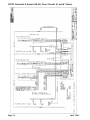
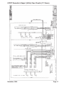
1
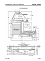
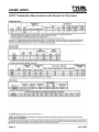
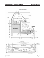
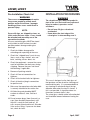
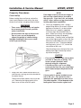
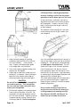
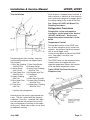
Installation & Service
Manual
LPFMT, LPFDT
DOME-TOP SERVICE/SELF-SERVICE COMBINATION MERCHANDISERS
Medium Temperature Service Display Cases
This manual has been designed to be used in conjunction with the
General (UL/NSF) Installation & Service Manual.
Save the Instructions in Both Manuals for Future Reference!
This merchandiser conforms to the American National Standard Institute & NSF International Health and Sanitation standard ANSI/NSF - 7 2003.
PRINTED IN Specifications subject to REPLACES
IN U.S.A.
change without notice. EDITION
4/04
ISSUE
DATE
7/07
Tyler Refrigeration * Niles, Michigan 49120
PART
NO.
9808205
REV.
C
LPFMT, LPFDT
CONTENTS
Page
Specifications
LPFMT/LPFDT Specification Sheets . . . . . . . . . . . . . . . . . . . . . . . . . 4
Line Sizing Requirements . . . . . . (See General-UL/NSF I&S Manual)
Pre-Installation Responsibilities . . . . . (See General-UL/NSF I&S Manual)
Pre-Installation Check List . . . . . . . . . . . . . . . . . . . . . . . . . . . . . . . . . 8
Installation Procedures . . . . . . . . . . . . . . . . . . . . . . . . . . . . . . . . . . . . . . . . 8
Carpentry Procedures . . . . . . . . . . . . . . . . . . . . . . . . . . . . . . . . . . . 9
Case Line-Up . . . . . . . . . . . . . . . . . . . . . . . . . . . . . . . . . . . . . . . . . . 9
Lift Dome Glass Leveling Instructions . . . . . . . . . . . . . . . . . . . . . . . 10
Trim Installation . . . . . . . . . . . . . . . . . . . . . . . . . . . . . . . . . . . . . . . . 11
Plumbing Procedures . . . . . . . . (See General-UL/NSF I&S Manual)
Refrigeration Procedures . . . . . . . . . . . . . . . . . . . . . . . . . . . . . . . 11
Temperature Control . . . . . . . . . . . . . . . . . . . . . . . . . . . . . . . . . . . . 11
Setting the Electronic Thermostat (LPFMT Top Dome) . . . . . . . . . 12
Electrical Procedures . . . . . . . . . . . . . . . . . . . . . . . . . . . . . . . . . . . 13
Electrical Considerations . . . . . . . . . . . . . . . . . . . . . . . . . . . . . . . . . 13
Case Fan Circuit . . . . . . . . . . . . . . . . . . . . . . . . . . . . . . . . . . . . . . . . 13
Fluorescent Lamp Circuit . . . . . . . . . . . . . . . . . . . . . . . . . . . . . . . . . 13
Defrost Information . . . . . . . . . . . . . . . . . . . . . . . . . . . . . . . . . . . . 13
Defrost Control Chart . . . . . . . . . . . . . . . . . . . . . . . . . . . . . . . . . . . 13
Installation Procedure Check Lists (See Gen.-UL/NSF I&S Manual)
Wiring Diagrams . . . . . . . . . . . . . . . . . . . . . . . . . . . . . . . . . . . . . . . . . . . 13
LPFMT Case Circuits (6’, 8’ & 12’ Cases) . . . . . . . . . . . . . . . . . . . . 14
LPFDT Case Circuits (6’, 8’ & 12’ Cases) . . . . . . . . . . . . . . . . . . . . 16
Cleaning and Sanitation
Component Removal and Installation Instructions for Cleaning
Dome Top Lower Trays . . . . . . . . . . . . . . . . . . . . . . . . . . . . . . . . . . 18
Dome Top Front Air Ducts (LPFDT) . . . . . . . . . . . . . . . . . . . . . . . . . 18
Dome Top Rear Air Ducts (LPFDT) . . . . . . . . . . . . . . . . . . . . . . . . . 18
Dome Top Mullion Covers . . . . . . . . . . . . . . . . . . . . . . . . . . . . . . . . 18
Lower Shelves and Shelf Brackets . . . . . . . . . . . . . . . . . . . . . . . . . 18
Lower Bottom Trays and Screens . . . . . . . . . . . . . . . . . . . . . . . . . . .18
Lower Front Air Ducts . . . . . . . . . . . . . . . . . . . . . . . . . . . . . . . . . . . 18
Lower Rear Duct Panels (w/o Shelf Light Sockets) . . . . . . . . . . . . 18
(with Shelf Light Sockets) . . . . . . . . . . . . . . . . . . . . . . . . . . . . . . . . 18
Page 2
April, 2007
Installation & Service Manual
LPFMT, LPFDT
Page
Lower Discharge Air Honeycomb . . . . . . . . . . . . . . . . . . . . . . . . . . 19
Lower Front Cladding . . . . . . . . . . . . . . . . . . . . . . . . . . . . . . . . . . . 19
Cleaning Instructions . . . . . . . . . . . . . . . . . . . . . . . . . . . . . . . . . . 19
Stainless Steel Cleaning Methods . . . . . . . . . . . . . . . . . . . . . . . 20
General Information
Rear Sliding Door Removal and Installation . . . . . . . . . . . . . . . 22
Top Mounted Scale Shelf Installation . . . . . . . . . . . . . . . . . . . . 23
Radiant Heat Information . . . . . . . . . . . . . . . . . . . . . . . . . . . . . . . 23
Service Instructions
Preventive Maintenance . . . . . . (See General-UL/NSF I&S Manual)
Fan Blade & Motor Replacement . (See Gen.-UL/NSF I&S Manual)
Connecting the Refrigeration Piping and Components . . . . . . . 24
Light Servicing . . . . . . . . . . . . . . . . . . . . . . . . . . . . . . . . . . . . . . . . 24
Ballast and Lighting Locations . . . . . . . . . . . . . . . . . . . . . . . . . . . . . 25
Lift-Glass Replacement . . . . . . . . . . . . . . . . . . . . . . . . . . . . . . . . . 25
Lift-Glass Gas Piston Replacement . . . . . . . . . . . . . . . . . . . . . . . 26
Lower Front Glass Replacement . . . . . . . . . . . . . . . . . . . . . . . . . 27
Parts Information
Cladding and Trim Parts List . . . . . . . . . . . . . . . . . . . . . . . . . . . . . 28
Operational Parts List . . . . . . . . . . . . . . . . . . . . . . . . . . . . . . . . . . 30
TYLER Warranty . . . . . . . . . . . . . . . . . (See General-UL/NSF I&S Manual)
The following Medium Temperature Lift Front Straight Glass Service/Self-Service Meat/Seafood/
Deli Combination Merchandiser models are covered in this manual:
MODEL
DESCRIPTION
LPFMT
6’, 8’ & 12’ LIFT GLASS DOME TOP GRAVITY COIL SERVICE/SELF-SERVICE
MED TEMP MEAT COMBINATION MERCHANDISERS
LPFDT
6’, 8’ & 12’ LIFT GLASS DOME TOP BLOWER COIL SERVICE/SELF-SERVICE
MED TEMP DELI COMBINATION MERCHANDISERS
April, 2007
Page 3
LPFMT, LPFDT
SPECIFICATIONS
LPFMT Combination Merchandisers with Gravity/Serpentine Coil Top Dome
Page 4
July, 2007
Installation & Service Manual
July, 2007
LPFMT, LPFDT
Page 5
LPFMT, LPFDT
LPFDT Combination Merchandisers with Blower Coil Top Dome
Page 6
July, 2007
Installation & Service Manual
April, 2007
LPFMT, LPFDT
Page 7
LPFMT, LPFDT
Pre-Installation Check List
WARNING
These cases are very heavy and require
two or more people to unload, move,
position and/or install them. Improper
handling of these cases could result in
personal injury.
NOTE:
Cases with legs are shipped to stores on
skids under the base frame. Cases should
be unloaded and moved by one of the
conventional methods
INSTALLATION PROCEDURES
WARNING
The raised front glass does not project in
front of the case, but could cause personal
injury to workers, operators and/or
customers.
• Do not leave lift glass raised and
unattended.
• Know where the front edge of the
raised glass is when working near it.
All cases containing glass MUST be stored
and installed on level surfaces to avoid
possible product damage and/or glass
breakage.
1. Check for hidden damage while
unloading and unpacking of the case.
2. Check the “shipped loose” parts for any
items; such as legs, shelves, nuts and
bolts, caulking, access doors, etc.
3. Check the equipment - remove the screws
used to hold down the deck pans during
shipping. Remove the pans and check
the following, if applicable:
4. Remove all packing material.
5. Check all flare nut connections for
tightness.
6. Check all fan bracket bolts for tightness.
7. Check all electrical plug-in connections
for positive seal.
8. Make sure the expansion valve feeler bulb
is securely attached to the suction line.
9. All field wiring and plumbing MUST
conform to national, state, and local
codes.
10. Do not remove plugs (from flare nuts) or
caps (from threaded connections) until
the unit is ready for final hook-up. All
coils are pressurized and have a Schrader
Valve access fitting. If pressure has been
lost, check for leaks.
Page 8
This case is designed so the front glass of
the top dome can be raised for cleaning and
merchandising only. It is recommended that
any cleaning or merchandising of the top
dome be done when the store is closed. If
this is not possible, it should be done at a
time when customer traffic is low.
The raised glass should not be left unattended
and should be lowered whenever leaving the
case.
April, 2007
Installation & Service Manual
Carpentry Procedures
Case Line-Up
Before starting the case line-up, review the
store layout floorplans and survey the areas
where case line-ups are going to be installed.
WARNING
• These cases are very heavy and require
two or more people to move, position
and/or install them.
• Do not walk on the tops of these cases.
Tops of cases are not designed to
support the weight of a human being.
Improper handling of these cases could
result in personal injury.
LPFMT, LPFDT
NOTE
Front edges of base rail and rear edges of
the case legs should always be used to
line-up cases. Case base rails are leveled
with 6” shims, while case legs have built-in
leveling adjustment capabilities.
2. Cases are shipped on skids. Using a
proper lifting devise, lift case off skid and
position case where it is to be installed.
While the case is properly supported,
install rear legs into threaded holes in
base. Make sure all legs are completely
threaded into the base to properly
secure them. Carefully lower and position
case at the highest point on the chalk line.
Shim front and middle base rails to level
fron posion of case. Thread out bottom
rear leg inserts, up to 1 1/2”, to level the
rear portion of the case.
Check leveling across the top of the case,
bottom front edge of dome top and on
top of the front glass.
CAUTION
• Case must be leveled from front to back
and side to side prior to joining. This
insures proper operation, water
drainage and glass alignment.
• If the base of this case is not sitting
evenly on the floor, the case could warp
when loaded and possibly break the lift
glass.
1. Snap chalk lines where the front base rail
and the rear case legs are to be located for
the entire line-up.
Check level of floor where cases are to be
set. Determine the highest point of the
floor; cases will be set off this point.
November, 2004
NOTE
A foam gasket is factory installed on one
end of the case. This gasket fits into a
groove on the adjoining case when cases
are pulled together. Do not depend on the
foam gasket alone to make a good seal!
Page 9
LPFMT, LPFDT
Lift Dome Glass Leveling Instructions
Accurate leveling is critical for the proper
operation of the lift dome glass on this case.
In some instances, setting the case on an
apparently level floor can cause the lift glass
to fit improperly. If there is any twist in the
body, it could cause the lift glass not to fit
or work properly.
The emphasis when leveling this case must
be on making sure the lift glass works and
seals properly.
3. Apply two heavy beads of caulking
compound from the Filler Kit to the end
of case at dotted (. . .) and dashed (- - -)
lines. Proper caulking provides good
case refrigeration and sanitation.
The case should be leveled across the top (1),
close to the hinge, and on the top of the front
cladding (2). A 4 foot level is recommended,
and both places should be level! This will
enable the lift glass to fit and work properly.
4. Push cases tightly together making sure
the pull-ups are aligned.
If the lift dome glass still doesn’t close or
line-up properly, adjust the rear legs or shim
the base rails at the corners. Leg adjustment
or shimming will ensure proper operation and
alignment of the lift dome glass.
5. Adjust legs or add shims under the end
pedestals, as required. Check leveling at
top of the case, bottom front edge of
dome top and on top of the front glass.
CAUTION
Do not drill or use other holes through the
case end for pull-ups. This may deform
the case end and could cause joint leaks
and/or poor refrigeration.
6. Position pull-up bolts and mounting hardware at pull-up locations (A and B). Do
not tighten any pull-up hardware until all
of it has been installed. Tighten all pull-up
hardware equally starting at point A and
finishing at point B. Do not overtighten.
Page 10
The inside bottom edge of the lift dome glass
must rest evenly on the glass support trim.
Proper lift glass sealing is essential for good
product refrigeration.
NOTE
Do not anchor the base to the floor or
enclose the case until the lift dome glass
is fitting properly and working correctly.
See “General (UL/NSF) I&S Manual” for
further line-up assembly instructions.
April, 2007
Installation & Service Manual
Trim Installation
LPFMT, LPFDT
Patch end trim is shipped factory installed. If
field installation is required, be sure the patch
end is pulled up enough to fit snuggly against
the sealing tubing on the inside of the case.
See “General (UL/NSF) I&S Manual” for
Plumbing Procedures.
Refrigeration Procedures
Refrigeration system and superheat
instructions can be found in the “General
(UL/NSF) I&S Manual”. Service case
temperature control information is listed
below.
Temperature Control
The folowing joint trims, backers, end trims
and mounting hardware are shipped loose.
Trim includes:
1) Rear Top Cladding 7) Color Band Backer
Joint/End Trim
8) Bumper Backer
2) Interior Dome
9) Lower Front Cladding
Joint Trim Kit
Joint/End Trim
3) Front Dome Duct 10) Kickplate Joint Trim
Joint/End Trim
11) Horizontal
4) Upper Cladding
Joint Trim
Joint Trim
12) Rear Base Closeoff*
5) Rear Lower Duct 13) Lower Rear Cladding
Joint Trim
Joint/End Trim*
6) Front Glass
14) Upper Rear Cladding
Joint Trim
Joint/End Trim*
The top dome section of the LPFMT case
has an extra thermostat and a suction line
solenoid. An additional liquid line solenoid
with an on-off toggle switch
isolates the top dome section on the LPFMT
case. See pages 4 and 6 for case
specifications.
The LPFMT cases use the thermostat, extra
solenoid valves and toggle switch for
improved temperature control and isolation
of the top dome refrigeration system.
Typical LPFMT Top Dome Gravity and
Serpentine Coils
* Optional trim components.
Horizontal joint trim covers gaps between the
cases. The trim is glued onto the shipping
cardboard. If trim has a notched side, apply
trim with notched side towards front of case,
after running beads of caulking on the edges
of the cases. Sheet metal screws can be used
for additional securing.
July, 2007
Page 11
LPFMT, LPFDT
Setting the Electronic Thermostat
(LPFMT - Top Dome)
1. Remove the four screws and cover from
the electronic thermostat.
2. Connect sensor wires to the common
(COM) and sensor (SEN) terminals of the
terminal strip located at the top left of the
printed circuit board. The sensor leads
are interchangeble.
7. To adjust the setpoint:
a. Push the Menu Button. “SP” will flash
on the LCD display.
b. Push the Menu Button one more time
and a setpoint temperature will be
displayed.
c. Push the Up or Down Button until the
desired setpoint is displayed.
(LPFMT - Top Dome = 20°F)
d. Push the Menu Button.
8. To adjust the differential:
3. Set the Heating/Cooling jumper blocks to
the “COOL” position.
4. Set the Cut-in at Setpoint/Cut-out at
Setpoint jumper blocks to the “Cut-out at
Setpoint” position.
5. Set the Keypad Locked/Unlocked jumper
blocks to the “Unlocked” position.
6. Replace the electronic thermostat cover
and secure with four screws.
a. Push the Menu Button. “SP” will flash
on the LCD display.
b. Push the Down Button until “DIF” is
shown on the LCD display.
c. Push the Menu Button one more time
and a differential number will be
displayed.
d. Push the Up or Down Button until
the desired differential setting is
displayed. (LPFMT - Top Dome = 9°F)
d. Push the Menu Button.
With the cooling mode selected, the
differential is ABOVE the setpoint. The relay
will be energized and the LED indicator will
illuminate when the temperature reaches the
differential setting. When the temperature
drops to the setpoint, the relay and LED
indicator will de-energize and refrigeration
will stop.
The settings above are specific to TYLER
service cases. Other applications will require
different setpoints and differentials.
Page 12
April, 2007
Installation & Service Manual
LPFMT, LPFDT
*NOTE:
Electrical Procedures
Electrical Considerations
CAUTION
Make sure all electrical connections at
components and terminal blocks are tight.
This prevents burning of electrical terminals and/or premature component failure.
NOTE
The ballast box is located at the lower right
rear corner of the case. It houses ballasts
and terminal blocks.
Case Fan Circuit
This circuit is to be supplied by an
uninterrupted, protected 120V circuit. The
case fan circuit is not cycled on this case.
The fan circuit consists of 2-3 fans for the
LPFMT, or 4-6 fans for the LPFDT.
Fluorescent Lamp Circuit
Case lighting is supplied by T-8 electronic
ballast lights. It is controlled by a light switch
in each case. The standard lighting is 1-row
of dome lights and 1-row of canopy lights.
2-rows of optional shelf lights are available.
• The LPFMT has a thermostat and
suction line solenoid to improve the
temperature control in the top dome
section.
• A toggle switch with a liquid line
solenoid isolates the top dome section
from the lower section.
WIRING DIAGRAMS
ELECTRICIAN NOTE - OVERCURRENT
PROTECTION
120V circuits should be protected by 15 or 20 Amp
devices per the requirements noted on the cabinet
nameplate or the National Electrical Code, Canadian
Electrical Code - Part 1, Section 28. 208V defrost
circuits employ No. 12 AWG field wire leads for field
connections. On remote cases intended for end to
end line-ups, bonding for ground may rely upon the
pull-up bolts.
The following wiring diagrams on pages 14
thru 17 will cover the LPFMT and LPFDT
case, defrost and lighting circuits.
Defrost Information
See “General (UL/NSF) I&S Manual” for
operational descriptions for Off Time
defrost control.
Defrost Control Chart
LPFMT Defrost Option Settings
Defrost
Defrost Defrosts Duration
Per Day
(Min)
Type
Off Time
4
40*
Term.
Temp.
-----
LPFDT Defrost Option Settings
Defrost
Defrost Defrosts Duration
Per Day
(Min)
Type
Off Time
4
40
November, 2004
Term.
Temp.
-----
Page 13
LPFMT Domestic & Export (50 Hz) Case Circuits (6’ and 8’ Cases)
Page 14
July, 2007
LPFMT Domestic & Export (50 Hz) Case Circuits (12’ Cases)
July , 2007
Page 15
LPFDT Domestic & Export (50 Hz) Case Circuits (6’ and 8’ Cases)
Page 16
April, 2007
LPFDT Domestic & Export (50 Hz) Case Circuits (12’ Cases)
November, 2004
Page 17
LPFMT, LPFDT
CLEANING AND SANITATION
Lower Shelves and Shelf Brackets
Component Removal and
Installation Instructions for
Cleaning
1. Remove product from shelves.
Dome Top Lower Trays
2. If shelf has a light, unplug the light cord
from socket from the rear duct panel.
Completely insert socket cover in the
light socket to protect the receptacle.
1. Open the front straight glass by lifting
at the bottom of the glass panel.
3. Push shelves back and then lift up and out
to remove them from the shelf brackets.
2. Remove product from the case interior.
4. Remove shelf brackets from slots in rear
uprights.
3. Grasp and lift out each lower tray from the
bottom of the dome top.
5. After cleaning, replace in reverse order.
4. After cleaning, replace in reverse order.
Lower Bottom Trays
Dome Top Front Air Ducts (LPFDT)
1. Remove product from bottom of case.
1. Remove lower trays, see this page.
2. Grasp and lift each of the bottom trays
from the case interior.
2. Lift out front air duct sections.
3. After cleaning, replace in reverse order.
3. After cleaning, replace bottom trays with
lips down in reverse order.
Dome Top Rear Air Ducts (LPFDT)
Lower Front Air Ducts
1. Remove lower trays, see this page.
1. Remove bottom trays, see above.
2. Remove mounting screws from rear
air duct.
2. Lift out front air duct sections.
3. Lift out rear air duct sections.
4. After cleaning, replace in reverse order.
Dome Top Mullion Covers
1. Open the front straight glass by lifting
the handle at the bottom.
2. Remove mounting screws from each
mullion cover.
WARNING
Mullion covers with electrical receptacles
can be cleaned without removing the
electrical receptacles. Do not get moisture
on electrical wires when cleaning under
this cover. Moisture on wires could cause
premature product failure and/or personal
injury or death from electrical shock.
3. Carefully remove each mullion cover from
the rear uprights.
4. After cleaning, replace and secure mullion
covers in reverse order.
Page 18
3. After cleaning, replace in reverse order.
Lower Rear Duct Panels
(w/o Shelf Light Sockets)
1. Remove shelves and bottom trays, see
above.
2. Remove mounting screws and rear duct
panels from case.
3. After cleaning, replace and secure rear
duct panels in reverse order.
(with Shelf Light Sockets)
1. Remove shelves and bottom trays, see
above.
2. Remove mounting screws from rear duct
panels.
3. Slowly lift out each rear duct panel until the
shelf harness connector can be accessed.
4. Disconnect shelf harness connector and
complete removing the rear duct panels.
April, 2007
Installation & Service Manual
WARNING
Rear duct panels with receptacles can be
cleaned without removing the electrical
receptacles. Do not get moisture on
electrical wires when cleaning under this
cover. Moisture on wires could cause
premature product failure and/or personal
injury or death from electrical shock.
5. After cleaning, reconnect each shelf harness connector and replace and secure
the rear duct panels in reverse order.
Lower Discharge Air Honeycomb
NOTE
Note position of the honeycomb grid
during removal so it can be reinstalled
the same way.
1. Remove screws, bottom retainer plate
and honeycomb grids from rear top duct.
CAUTION
Improper installation of the honeycomb
grid could result in improper air flow
and/or poor refrigeration.
2. After cleaning, replace honeycomb grid
sections as they were removed and
secure with the bottom retainer plate
and screws.
Lower Front Cladding
LPFMT, LPFDT
Cleaning Instructions
WARNING
TYLER Refrigeration does not recommend
the use of high pressure cleaning equipment on service style cases!! The sealing
of front glass and end joints is critical in
these cases and high pressure cleaners
can penetrate and/or damage these seals.
Damaged seals allow water leaks and/or
air leaks that can cause poor case
refrigeration.
CAUTION
• When cleaning this case, try not to
introduce water into the case faster
than it can be carried away by the
waste outlet.
• Liquid chlorine bleach is corrosive to
metals. The use of bleach or products
containing bleach will damage metal
surfaces and void the case warranty.
• Sanitize the case with Quaternary
Ammonium Solutions (ex: KAYQUAT II,
J-512 Sanitizer, SANIQUAT 512, etc...)
approved per 21CFR 178.1010, followed
by adequate draining and air drying.
These solutions may be obtained from
Kay Chemical Co., Johnson Wax
Professional, Coastwide Laboratories,
etc....
1. Wipe surface clean with a damp soapy
cloth.
• Always use a soft cloth or sponge with
mild detergent and water to clean the
front glass. Never use abrasives or
scouring pads to clean glass. They
can scratch and/or damage the glass.
2. Rinse with clean damp cloth and dry
surface completely.
See “General (UL/NSF) I&S Manual” for
case cleaning instructions.
NOTE
Lower front cladding is not removable.
April, 2007
Page 19
LPFMT, LPFDT
Stainless Steel Cleaning Methods
The cleaning data in the following stainless steel cleaning chart was supplied by AISI. The information was supplied by
Prime Metals Division, Alumax Aluminum Corporation.
TYPE OF CLEANING
CLEANING AGENT*
APPLICATION METHOD**
EFFECT ON FINISH
Routine cleaning
Soap, ammonia or detergent and water.
Sponge with cloth, then
rinse with clear water and
wipe dry.
Satisfactory for use on all
finishes.
Smears and fingerprints
Arcal 20, Lac-O-Nu, Lumin
Wash O’Cedar Cream
Polish, Stainless Shine
Rub with cloth as directed
on the package.
Satisfactory for use on all
finishes. Provides barrier film
Apply with damp sponge or
cloth.
Satisfactory for use on all
finishes.
Rub with damp cloth.
Satisfactory for use on all
finishes if rubbing is light.
Grade FFF Italian pumice,
whiting or talc
Rub with damp cloth.
Use in direction of polish lines
on No. 4 (polished) finish.
May scratch No. 2 (mill) and
No. 7 and 8 (polished) finishes.
Liquid NuSteel
Rub with dry cloth. Use a
small amount of cleaner.
Use in direction of polish lines
on No. 4 (polished) finish.
May scratch No. 2 (mill) and
No. 7 and 8 (polished) finishes.
Paste NuSteel or DuBois
Temp
Rub with dry cloth. Use a
small amount of cleaner.
Use in direction of polish lines
on No. 4 (polished) finish.
May scratch No. 2 (mill) and
No. 7 and 8 (polished) finishes.
Cooper’s Stainless Steel
Cleaner, Revere Stainless
Steel Cleaner
Apply with damp sponge or.
cloth.
Use in direction of polish lines
on No. 4 (polished) finish.
May scratch No. 2 (mill) and
No. 7 and 8 (polished) finishes.
Stubborn spots and
Allchem Concentrated
stains, baked-on
Cleaner
splatter, and other light
discolorations
Samae, Twinkle, or Cameo
Copper Cleaner
Heat tint or heavy
discoloration
Page 20
Grade F Italian pumice, Steel Rub with a damp cloth.
Bright, Lumin Cleaner, Zud or
Restoro
Use in direction of polish lines
on No. 4 (polished) finish.
May scratch No. 2 (mill) and
No. 7 and 8 (polished) finishes.
Penny-Brite or Copper-Brite
Rub with a dry cloth. Use a
small amount of cleaner.
Use in direction of polish lines
on No. 4 (polished) finish.
May scratch No. 2 (mill) and
No. 7 and 8 (polished) finishes.
Penny-Brite or Copper-Brite
Rub with a dry cloth.
Use in direction of polish lines
on No. 4 (polished) finish.
May scratch No. 2 (mill) and
No. 7 and 8 (polished) finishes.
Paste NuSteel or DuBois
Temp
Rub with dry cloth. Use a
small amount of cleaner.
Use in direction of polish lines
on No. 4 (polished) finish.
May scratch No. 2 (mill) and
No. 7 and 8 (polished) finishes.
April, 2007
Installation & Service Manual
LPFMT, LPFDT
TYPE OF CLEANING
CLEANING AGENT*
APPLICATION METHOD**
EFFECT ON FINISH
Revere Stainless Steel
Cleaner
Apply with a damp sponge
or cloth.
Use in direction of polish lines
on No. 4 (polished) finish.
May scratch No. 2 (mill) and
No. 7 and 8 (polished) finishes.
Allen Polish, Steel Bright,
Wyandotte, Bab-O or Zud
Rub with a damp cloth.
Use in direction of polish lines
on No. 4 (polished) finish.
May scratch No. 2 (mill) and
No. 7 and 8 (polished) finishes.
Burnt-on foods and
grease, fatty acids,
milkstone (where swabbing or rubbing is not
practical)
Easy-Off, De-Grease-It, 4-6%
hot solution of such agents
as trisodium tripolyphospate,
or 5-15% caustic soda
solution
Apply generous coating.
Allow to stand for 10-15 min.
Repeated application may
be necessary.
Excellent removal, satisfactory
for use on all finishes.
Tenacious deposits,
rusty discolorations,
industrial atmospheric
stains
Oakite No. 33, Dilac, Texo 12,
Texo N.Y., Flash-Klenz,
Caddy Cleaner, Turco Scale
4368 or Permag 57.
Swab and soak with clean
cloth. Let stand 15 minutes
or more according to directions on package. Rinse
and dry.
Satisfactory for use on all
finishes.
Hard water spots
and scale
Vinegar
Swab or wipe with a cloth.
Rinse with water and dry.
Satisfactory for use on all
finishes.
5% oxalic acid, 5% sulamic
acid, 5-10% phospheric acid,
or Dilac, Oakite No. 33,
Texo 12 or Texo N.Y.
Swab or soak with a cloth.
Let stand 10-15 minutes.
Always follow with neutralizer
rinse, and dry.
Satisfactory for use on all
finshes. Effective on tenacious
deposites or where scale has
built up.
Organic solvents such as
carbon tetrachloride, trichlorethylene, acetone, kerosene, gasoline, benzene,
alcohol and chlorethane n.u.
Rub with a cloth. Organic
solvents may be flammable
and/or toxic. Observe all
precautions against fire.
Do not smoke while vapors
are present. Be sure area
is well ventilated.
Satisfactory for use on all
finishes.
Grease and oil
*
Use of proprietary names is intended only to indicate a type of cleaner, and does not constitute an endorsement, nor is
omission of any proprietary cleanser to imply its inadequacy. It should be emphasized that all products should be used
in strict accordance with instructions on package.
**
In all applications a sponge or fibrous brush or pad are recommended. DO NOT use ordinary
steel wool, steel brushes, chlorine bleach or products containing bleach for cleaning stainless steel.
April, 2007
Page 21
LPFMT, LPFDT
GENERAL INFORMATION
Rear Sliding Door Removal
and Installation
The sliding doors come installed from the
factory in the door frames. These doors are
removable for cleaning and to aid in case
maintenance. NOTE: DO NOT FULLY
IMMERSE DOORS WHEN CLEANING.
The inner and outer doors are marked with
labels from the factory. If the doors are not
labeled, the inner door can be identified as
having the limiter stops on it.
1. Remove the outer door (1) by sliding it to
the right end of the door frame (2) (within
an inch of being closed).
3. Tilt out the bottom of the outer door (1)
so it can clear the lower track (4).
4. Lower the outer door (1) out of the upper
track (3) to remove it from the case.
5. Repeat steps 1 thru 4 to remove the
inner door (5).
6. Reverse the above steps to replace the
inner and outer doors (5 and 1).
2. Firmly grasp both sides of the outer door
(1) and lift into the upper track (3) until it
clears the lower track (4).
Page 22
April, 2007
Installation & Service Manual
Top Mounted Scale Shelf
Installation
The optional scale shelf is mounted to the
top center of the case and the center mullion
on the back of the case.
NOTE
If the reinforcement is shipped loose, align
with the center two holes in the bracket
and attach during installation.
LPFMT, LPFDT
2. Attach scale shelf (1) to top of case with
three stainless steel screws (3) in the front
top edge and 4 swedge bolts (4) through
the reinforcement and bracket into the
back of the case.
NOTE
Make sure the scale shelf stays level
during the scale shelf support installation.
3. Install the scale shelf support (5) under
the rear center of the scale shelf (1) and
secure it to the rear center mullion (2) with
two swedge bolts (6). (The support is not
mechanically attached to the scale shelf.)
Radiant Heat Information
The scale shelf panel, reinforcement, and
bracket should be shipped as a pre-assembled unit from the factory. Use the follow
instructions to mount the scale shelf
assembly.
1
3
A wide temperature range is shown for each
type of lighting. This data does not show all
situations. Many situations will have higher
package warm-up figures than indicated.
5
6
2
4
1. Align scale shelf (1) so center of the shelf
lines up with the center rear mullion (2).
November, 2004
It is generally known that the temperature of
displayed meat in refrigerated cases will run
higher than the circulated air temperature of
the cases. A dial thermometer stuck into the
Page 23
LPFMT, LPFDT
center of a piece of meat compared with one
in the air stream quickly confirms this fact.
Another fact is that the surface temperature
of the meat will be higher than the center
temperature due to radiant heat. TYLER’s
ongoing research identifies sources of
radiant heat and accurately measures and
records it. These charts were developed
from the information gathered during this
research. Two major sources of radiant heat
are from display lights and ceiling surfaces.
Additional heat sources come from bad
display practices which either overload the
case with product or allow voids in the
product display. Poor display practices
impair the efficiency of the refrigeration,
adding to the surface temperature of the
meat. Bacteria and molds grow when surface
temperatures rise above 45°F. This prematurely discolors displayed meats and causes
unnecessary meat department losses.
SERVICE INSTRUCTIONS
Radiant Heat Measurement
• Mount all refrigeration lines off the floor
to allow for cleaning access.
Place two accurate dial thermometers side by
side in a case. Cover one of the thermometer
stems with black friction tape. The temperature difference is the approximate amount of
radiant heat. A change in display lighting or
a reduction of high ceiling temperatures
(over 80°F) could reduce the radiant heat in
the case.
Display Practices
Encourage butchers
to maintain all meat
below the case load
lines and to eliminate
product voids. Case screens could be
covered in some instances to keep the
refrigerated air over the display.
Connecting the Refrigeration
Piping and Components
WARNING
Be sure to position a flame and heatresistent shield over the bottom of the
case liner. Heat from brazing could
damage the liner and/or cause personal
injury or death from fire.
1. Remove screws and refrigeration piping
cover from the left bottom of the case.
2. Position loose refrigeration piping and/or
optional valves between the open lines in
the bottom and upright of the case.
NOTE
• Make sure all sensor and thermostat
wires are clear of areas being heated.
3. Apply flux to all joint ends. Starting at one
end, thoroughly heat each new pipe joint
and braze it together. Repeat this process
until all new pipe joints have been brazed.
4. After piping has cooled, route and
connect thermostat and sensor wires
through openings in the bottom of
the case.
Light Servicing
See “General (UL/NSF) I&S Manual” for
preventive maintenance, T-8 lamp, fan
blade and fan motor (TLD) replacement
instructions replacement
CAUTION
The quality damage done to meat products
by high temperatures and/or contamination
during delivery, cooler storage, cutting and
wrapping cannot be repaired by placing
the products into properly operating
display cases.
Page 24
April, 2007
Installation & Service Manual
Ballast and Lighting Locations
LPFMT, LPFDT
Lift-Glass Replacement
WARNING
Wear safety glasses and gloves and use
at least two people when replacing glass.
Glass is heavy and weight distribution is
uneven. Mishandling of glass could cause
breakage and/or personal injury.
If replacing glass:
All light ballasts are located in an electrcal
box in the top of the rear storage cabinet at
the right rear of the case.
Underwriter’s Laboratory and the Canadian
Standards Association, the mounting of
electrical components and interconnecting
wires must not deviate from the following
instructions. Only qualified personnel are
authorized to install the accessory items.
TYLER Refrigeration recommends you
order all components from its Service Parts
Department.
Ballast Replacement
1. Remove screws and electrical box cover
from rear of case.
NOTE
If tappit screws are not available, a
starwasher should be used between the
ballast and the heads of the screws.
2. Install required number of ballasts in
electrical box with two screws each.
1. Raise the old glass to the full UP position.
NOTE
• Glass is heavy and requires assistance
for properly support.
• Note positioning and installation of top
edge channel before removing.
2. With assistants firmly holding both ends
of the glass (1), loosen the set screws (2)
in the back of the top edge channel (3)
with an allen wrench or allen head screw
driver.
3. Identify and connect required wiring
harnesses (upper, lower, etc...) to the
ballast connectors.
4. Replace electrical box cover and secure
with screws.
November, 2004
Page 25
LPFMT, LPFDT
3. Using a flathead screwdriver, push down
aluminum wedge inside top edge channel
(3), until it rests in bottom of the channel.
After wedge has been released from glass
(1), remove the old glass from
the top edge channel.
5. Position the top edge channel (3) on the
new glass panel (1) in same position as
removed.
NOTE
Glass must be fully inserted into top edge
channel before tightening.
• Do not attempt to perform any work on
case while piston is in compressed state.
• Raise glass to full UP position before
beginning any work involving gas
pistons.
• Do not attempt to alter a gas piston in
any way.
• Do not expose a gas piston to
excessive heat.
• Dispose of gas piston as soon as
possible after removal.
6. After glass (1) is positioned in the top
edge channel (3), tighten each set screw
(2) until glass is held into place by the
aluminum wedge. Do not overtighten.
6. With aid of assistants, lift and tentatively
position new glass assembly (1) in the
hinge slots. Tighten the hinge set screws
(2) (7 in•lb). Do not overtighten.
7. Slowly lower glass to check position. If
adjustment is necessary, raise glass and
have assistants hold both ends. Loosen
the hinge set screws, adjust the glass
assembly position and retighten set
screws to secure top edge channel in
hinge slot. Do not overtighten.
Lift-Glass Gas Piston
Replacement
WARNING
The LPFMT & LPFDT cases rely upon gas
pistons to assist lifting the glass and holding it in the raised position on the dome
top sections. The glass is heavy and difficult for one person to lift alone while
replacing
a gas piston. Use an assistant to prevent
possible glass breakage and/or personal
injury.
Each lift glass panel uses two gas pistons
and two hinges to support it. Examples: 6’
& 8’ cases have 2 lift glass panels mounted
on 3 support assemblies with 4 hinges and
4 gas pistons. 12’ cases have 3 lift glass
panels mounted on 4 support assemblies
with 6 hinges and 6 gas pistons.
1. Have an assitant lift and hold the glass in
the full UP position. Note position and
relationship of all glass lift components.
2. While lift glass is being held open,
Loosen set screw in end of piston rod with
a (size 2) allen wrench or allen head screwdriver. Carefully remove piston rod support
pin while supporting the piston with your
other hand. The piston will drop in your
hand when the support pin is removed.
Since gas pistons are very powerful when
in compressed state, follow these cautions
during replacement:
Page 26
April, 2007
Installation & Service Manual
NOTE
LPFMT, LPFDT
Front Lower Glass Replacement
Replacement piston should be of same
weight capacity as the piston being
replaced.
1. Remove screw (1), screw nut (2), glass
joint trim (3) and glass joint backer (4)
from both joints of the broken glass.
2. Remove glass trim rail (6) from top
of glass (5).
3. Install new gas piston by supporting base
end with rear support pin in back of
upright assembly. Rotate piston up to line
up rod end in hinge and secure in place
by inserting the piston rod support pin.
4. Tighten (size M4) set screw with a size 2
allen wrench or allen head screwdriver,
then unscrew 1/2 turn and secure with
Loctite or Weicon semi-hard.
5. Repeat steps 2 thru 4 until all bad gas
pistons have been replaced.
November, 2004
3. Loosen rear retainer (7) and remove
broken glass from glass retainer
assembly (8).
4. Apply sealant tape (9) to top and bottom
edge of new glass (5).
5. Position new glass (5) in glass retainer
assembly (8) and secure by tightening
rear retainer (7).
6. Install glass trim rail (6) over top edge of
new glass (5).
7. Install glass joint backer (4), glass joint
trim (3) with screw (1) and screw nut (2)
over both joint areas of the glass (5).
Page 27
LPFMT, LPFDT
PARTS INFORMATION
Cladding and Trim Parts List
Item Description
6’
8’
12’
1
Rear Top Cladding, Ptd.
9805072
9803124
9803127
2
Rr. Top Cladding Joint Trim, Ptd. 9805585
9805585
9805585
3
Front Duct Joint Trim, MB
9805575
9805575
9805575
Dome Int. Joint Trim Kit, MB
9805488
9805488
9805488
4
Top Cladding, MB
9805390
9805401
9805349
5
Top Cladding Joint Trim, MB
9805572
9805572
9805572
6
Rear Lower Duct Joint Trim
5237536
5237536
5237536
7
Front Glass Joint Trim
9806330
9806330
9806330
8
Top Glass Trim Rail
9805046
9026561
9026562
9
Front Glass Retainer
9026024
9026025
9026026
Rear Glass Retainer
9805047
9026549
9026550
Color Band, Ptd.
9025979
9036805
9036806
Color Band Backer, Ptd.
9025982
9025982
9025982
10
11
Bumper
---------- color per order ----------
Bumper Backer
---------- color per order ----------
Bumper Retainer
9025052
9025058
9025061
Front Lower Cladding, Ptd.
9805057
9801525
9801526
Frt. Lwr. Clad. Joint Trim, Ptd.
9805553
9805553
9805553
Kickplate, Ptd.
9039277
9039278
9802129
Kickplate Joint Trim, Ptd.
9039020
9039020
9039020
14
Kickplate Support Assembly
9043461
9043461
9043461
15
Opt. Base End Closeoff, Ptd.
(per patch end)
9803675
9803675
9803675
16
Horizontal End Trim
5964733
5964733
5964733
17
Rear Pipe Leg, Std. (1.5” X 4”) 9330018(3)
9330018(3)
9330018(4)
18
Rear Closeoff Assembly, Ptd.
9805668
9805669
9805670
19
Rear Lower Cladding, Ptd.
9805076
9803093
9803096
Rr. Lwr. Cladding Joint Trim, Ptd. 9805559
9805559
9805559
20
End Mullion Cover, Ptd.
9805083
9803115
9803115
21
Upper Rear Cladding Assy., Ptd. 9805673
9805676
9805679
22
Rr. Upr. Cladding Joint Trim, Ptd. 9805454
9805454
9805454
23
Ballast Box Cover
9803150
9803150
12
13
Page 28
9803150
April, 2007
Installation & Service Manual
November, 2004
LPFMT, LPFDT
Page 29
LPFMT, LPFDT
Operational Parts List
Case Usage
Domestic
Electrical Circuit
115 Volt 60 Hertz
Case Size
6’
8’
12’
Fan Motor
5243498
9 Watt
5243498
9 Watt
5243498
9 Watt
Fan Motor Brackets
5962268
5962268
5962268
Fan Bracket Plate
9041077
9041077
9041077
Fan Blades
(7” 10° 5B)(LPFDT Top Dome)
9805540
9805540
9805540
5960934
5960934
5960934
Opt. ECM Fan Motor (all models)
9025002
8 Watt
9025002
8 Watt
9025002
8 Watt
Opt. ECM Fan Motor Brackets
9025005
9025005
9025005
Opt. ECM Fan Blades
(7” 5° 5B)(LPFDT Top Dome)
9805539
9805539
9805539
5223891
8223891
5223891
Rocker Switch
5961377
5961377
5961377
Rectangular Outlet
5236335
5236335
5236335
T-8 Lamp Ballast
(top dome)(1-row)
5991029
5991029
5991030
(canopy)(1-row)
5991029
5991029
5991030
(opt. shelf)(per row)
5991029
5991029
5991030
T-8 Lampholder (top dome/canopy)
9041897
9041897
9041897
T-8 Shelf Harness
9027906
9027906
9027906
Hydro-Lift Gas Piston
9801274
9801274
9801274
Hydro-Lift Piston Tool
(Required to remove pistons)
5152656
5152656
5152656
Suction Solenoid Valve
(LPFMT Top Dome)
5191445
5191445
5191445
Liquid Solenoid Valve
(LPFMT Top Dome)
5084991
5084991
5084991
Electronic Thermostat
(LPFMT Top Dome)
9043552
9043552
9043552
Check Valve (LPFMT Top Dome)
5199417
5199417
5199417
(7” 20° 5B)(Self-Serve Sect. - All)
(7” 15° 5B)(Self-Serve Sect. - All)
For information on operational parts not listed above contact the TYLER Service
Parts Department.
Page 30
April, 2007