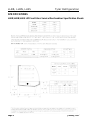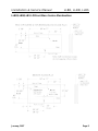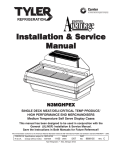
1
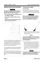
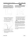
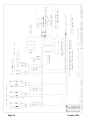
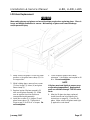
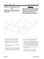
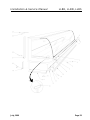
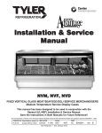
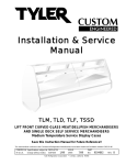
Installation & Service
Manual
LLBR, LLBN, LLBS
LIFT FRONT CURVED GLASS BAKERY MERCHANDISERS
Medium Temperature and Non-Refrigerated Bakery Display Cases
This manual has been designed to be used in conjunction with the General
Installation & Service Manual.
Save the Instructions in Both Manuals for Future Reference!!
This merchandiser conforms to the Commercial Refrigeration Manufacturers Association Health and Sanitation standard CRS-S1-96.
PRINTED IN Specifications subject to REPLACES
IN U.S.A.
change without notice. EDITION
1/97
ISSUE
DATE
7/99
Tyler Refrigeration Corporation * Niles, Michigan 49120
PART
NO.
9027543
REV.
B
LLBR, LLBN, LLBS
Tyler Refrigeration
CONTENTS
Page
Specifications
LLBR/LLBN/LLBS Specification Sheets . . . . . . . . . . . . . . . . . . . . . . 4
Line Sizing Requirements . . . . . . . . . . . . (See General I&S Manual)
Pre-Installation Responsibilities . . . . . . . . . . . (See General I&S Manual)
Installation Procedures
Carpentry Procedures . . . . . . . . . . . . . . . . . . . . . . . . . . . . . . . . . 6
Case Line-Up . . . . . . . . . . . . . . . . . . . . . . . . . . . . . . . . . . . . . . . . 6
Lift Glass Leveling Instructions . . . . . . . . . . . . . . . . . . . . . . . . . . . . 7
Trim Installation . . . . . . . . . . . . . . . . . . . . . . . . . . . . . . . . . . . . . . . 8
Plumbing Procedures . . . . . . . . . . . . . . (See General I&S Manual)
Refrigeration Procedures . . . . . . . . . . . (See General I&S Manual)
Self-Contained Circuit (LLBS) . . . . . . . . . . . . . . . . . . . . . . . . . . . . . 9
Electrical Procedures . . . . . . . . . . . . . . . . . . . . . . . . . . . . . . . . . . 9
Electrical Considerations . . . . . . . . . . . . . . . . . . . . . . . . . . . . . . . . 9
Defrost Information . . . . . . . . . . . . . . . . . . . . . . . . . . . . . . . . . . . . 9
Defrost Control Chart . . . . . . . . . . . . . . . . . . . . . . . . . . . . . . . . . . . 9
Installation Procedure Check Lists . . . . (See General I&S Manual)
Wiring Diagrams . . . . . . . . . . . . . . . . . . . . . . . . . . . . . . . . . . . . . . . . . . . 9
LLBR/LLBN Domestic & Export (50Hz) Case Circuits . . . . . . . . . . 10
LLBS Domestic & Export (50Hz) Case Circuits . . . . . . . . . . . . . . . 11
Cleaning and Sanitation
Stainless Steel Cleaning Methods . . . . . . . . . . . . . . . . . . . . . . . . 12
General Information
Rear Sliding Door Removal and Installation . . . . . . . . . . . . . . . . . 14
Page 2
October, 1996
Installation & Service Manual
LLBR, LLBN, LLBS
Page
Service Instructions
Preventive Maintenance . . . . . . . . . . . . (See General I&S Manual)
Troubleshooting Self-Contained Units (LLBS) . . . . . . . . . . . . . . . . 15
Light Servicing . . . . . . . . . . . . . . . . . . . . . . . . . . . . . . . . . . . . . . 16
Ballast and Lighting Locations . . . . . . . . . . . . . . . . . . . . . . . . . . . 16
Fan Blade and Motor Replacement . . . . (See General I&S Manual)
Color Band and Bumper Replacement . (See General I&S Manual)
Lift Glass Replacement . . . . . . . . . . . . . . . . . . . . . . . . . . . . . . . 17
Lift Glass Cylinder Replacement . . . . . . . . . . . . . . . . . . . . . . . . 18
Lift Glass End Seal Replacement . . . . . . . . . . . . . . . . . . . . . . . . 19
Parts Information
Operational Parts List . . . . . . . . . . . . . . . . . . . . . . . . . . . . . . . . . 19
Cladding and Trim Parts List . . . . . . . . . . . . . . . . . . . . . . . . . . . 19
TYLER Warranty . . . . . . . . . . . . . . . . . . . . . . . (See General I&S Manual)
The following Medium Temperature (Remote & Self-Contained) and Non-Refrigerated Lift Front
Glass Bakery Merchandiser models are covered in this manual:
MODEL
DESCRIPTION
LLBR
59” & 77” LIFT FRONT GLASS REMOTE OPERATED BAKERY MERCHANDISER
LLBN
59” & 77” LIFT FRONT GLASS NON-REFRIGERATED BAKERY MERCHANDISER
LLBS
59” & 77” LIFT FRONT GLASS SELF-CONTAINED BAKERY MERCHANDISER
January, 1997
Page 3
LLBR, LLBN, LLBS
Tyler Refrigeration
SPECIFICATIONS
LLBR/LLBN/LLBS Lift Front Glass Service Merchandiser Specification Sheets
Page 4
January, 1997
Installation & Service Manual
LLBR, LLBN, LLBS
LLBR/LLBN/LLBS Lift Front Glass Service Merchandiser
January, 1997
Page 5
LLBR, LLBN, LLBS
INSTALLATION PROCEDURES
WARNING
Tyler Refrigeration
Carpentry Procedures
Case Line-Up
The raised front glass projects in front of
the case and could cause personal injury to
workers, operators and/or customers.
Before starting the case line-up, review the
store layout floorplans and survey the areas
where case line-ups are going to be installed.
• Do not remove orange warning tags from
front edge of lift glass.
WARNING
• Do not leave lift glass raised and unattended.
• Know where the front edge of the raised
glass is when working near it.
These cases are very heavy and require
two or more people to move and/or position them. Improper handling of these
cases could result in personal injury.
1. Snap chalk lines where the front and rear
base rails of the case are to be located for
the entire line-up.
NOTE
This case is designed so the front glass can be
raised for cleaning and merchandising only. It
is recommended that any cleaning or merchandising be done when the store is closed.
If this is not possible, it should be done at a
time when customer traffic is low.
The raised glass should not be left unattended
and should be lowered whenever leaving the
case.
The glass front is marked with orange warning
tags to make it noticeable when in the raised
position. Do not remove the orange warning
tags.
Page 6
Front and rear edges of base rails should
always be used to line-up cases. 6” shims
allow adjoining ends of cases to be
shimmed together.
2. Locate highest point on chalk lines as a
reference for determining the number of
shims to be placed under the case base
rails. Position first case at highest point
on the chalk lines and shim case supports
as required. Check leveling across the
top of the case and on top of the color
band.
CAUTION
If the base of this case is not sitting evenly
on the floor, the case could warp when
loaded and possibly break the lift glass.
October, 1996
Installation & Service Manual
LLBR, LLBN, LLBS
NOTE
CAUTION
A foam gasket is factory installed on one
end of the case. This gasket fits into a
groove on the adjoining case when cases
are pulled together. Do not depend on the
foam gasket alone to make a good seal!
Do not drill or use other holes through the
case end for pull-ups. This may deform
the case end and could cause joint leaks
and/or poor refrigeration.
3. Apply two heavy beads of caulking compound from the Filler Kit to the end of
case at dotted (. . .) and dashed (- - -)
lines. Proper caulking provides good
case refrigeration and sanitation.
4. Remove shipping tape from color band
backer and bumper backer.
7. Position pull-up bolts and mounting hardware (5) at pull-up locations (A and B).
Do not tighten any pull-up hardware until
all of it has been installed. Tighten all
pull-up hardware equally starting at point
A and finishing at point B. Do not overtighten.
Lift Front Glass Leveling Instructions
Accurate leveling is critical for the proper
operation of the lift glass on this case.
In some instances, setting the case on an
apparently level floor can cause the lift glass
to fit improperly. If there is any twist in the
body, it could cause the lift glass not to fit or
work properly.
5. Push cases tightly together making sure
the pull-ups are aligned.
The emphasis when leveling this case must
be on making sure the lift glass works and
seals properly.
6. Add shims (1), as required, under the
adjoining case base rails (2). Check leveling at top of the case (3) and on top of
the color band (4).
October, 1996
Page 7
LLBR, LLBN, LLBS
Tyler Refrigeration
removed. Pre-prime the cylinders by gently
lifting the front glass approximately 6”, then
close. Repeat this movement at least 4 or 5
times before fully opening the lift glass.
The case should be leveled across the top,
close to the hinge, and on the color band. A
4 foot level is recommended, and both
places should be level! This will enable the
lift glass to fit and work properly.
If the lift glass still doesn’t close or line-up
properly, add shims to case corners.
Shimming will ensure proper operation and
alignment of the lift glass.
NOTE
If the glass does not stay in the open position, see “Lift Glass Cylinder Replacement”
in this manual.
Trim Installation
The handle on the lift glass must rest evenly
on the color band. Proper lift glass sealing is
essential for good product refrigeration.
NOTE
Do not anchor the base to the floor or
enclose the case until the lift glass is fitting properly and working correctly.
Pre-priming the hinge gas cylinders:
WARNING
If the front glass is raised before the hinge
gas cylinders are pre-primed, the glass
could break and/or cause personal injury.
After the case has been installed and leveled,
make sure the shipping braces have been
Page 8
The joint trim and mounting hardware are
shipped loose. Trim includes top joint trim
(1), rear upper joint trim (2), rear base joint
trim (3) and horizontal joint trim (4).
October, 1996
Installation & Service Manual
Horizontal joint trim covers gaps between the
cases. The trim is glued onto the shipping
cardboard. It is applied after running beads
of caulking on the edges of the cases. Sheet
metal screws or pop-rivets can be used for
additional securing.
Patch end trim is shipped factory installed. If
field installation is required, be sure the patch
end is pulled up enough to fit snuggly against
the sealing tubing on the inside of the case.
The patch end must seal tightly against the lift
glass wiper to ensure proper operating temperatures.
LLBR, LLBN, LLBS
Fluorescent Lamp Circuit
LLB(R/N/S) case lighting is supplied by
200MA T-6 lights. It is controlled by a light
switch in each case. The standard lighting is
2 rows of horizontal canopy lights.
Defrost Information
See “General I&S Manual” for operational
descriptions for each type of defrost control.
Defrost Control Chart
LLBR/LLBS Defrost Option Settings
Refrigeration Procedures
Defrost
Defrost Defrosts Duration
Per Day
(Min)
Type
Off Time
1
45
Refrigeration system and superheat
instructions can be found in the “General
I&S Manual”.
Thermostat bulb is located under the rear
duct, 24” from the right end of the evaporator
coil.
Self-Contained Circuit (LLBS Only)
WIRING DIAGRAMS
See “General I&S Manual” for bumper and
color band installation and alignment.
LLBS cases are self-contained units.
Information pertaining to self-contained units
should be obtained directly from TYLER
Refrigeration.
Electrical Procedures
Electrical Considerations
CAUTION
Make sure all electrical connections at
components and terminal blocks are tight.
This prevents burning of electrical terminals and/or premature component failure.
Term.
Temp.
-----
ELECTRICIAN NOTE - OVERCURRENT
PROTECTION
120V circuits should be protected by 15 or 20 Amp
devices per the requirements noted on the cabinet
nameplate or the National Electrical Code, Canadian
Electrical Code - Part 1, Section 28. 208V defrost
circuits employ No. 12 AWG field wire leads for field
connections. On remote cases intended for end to
end line-ups, bonding for ground may rely upon the
pull-up bolts.
The following pages 10 and 11 show wiring
diagrams for case and lighting circuits
NOTE
The ballast box is located at the lower left
rear corner of the case. It houses ballasts
and terminal blocks.
Case Fan Circuit (LLBR/LLBS)
This circuit is to be supplied by an uninterrupted, protected 120V circuit. The case fan
circuit is not cycled on this case.
October, 1996
Page 9
Page 10
October, 1996
January, 1997
Page 11
LLBR, LLBN, LLBS
Tyler Refrigeration
CLEANING INSTRUCTIONS
WARNING
TYLER Refrigeration does not recommend
the use of high pressure cleaning equipment on service style cases!! The sealing
of front glass and end joints is critical in
these cases and high pressure cleaners
can penetrate and/or damage these seals.
Damaged seals allow water leaks and/or
air leaks that can cause poor case refrigeration.
CAUTION
• When cleaning this case, try not to introduce water into the case faster than it
can be carried away by the waste outlet.
• Always use a soft cloth or sponge with
mild detergent and water to clean the
front glass. Never use abrasives or
scouring pads to clean glass. They can
scratch and/or damage the glass.
See “General I&S Manual” for case cleaning
instructions. Stainless steel cleaning is covered in the following chart.
Stainless Steel Cleaning Methods
The cleaning data in the following stainless steel cleaning chart was supplied by AISI. The information was supplied by
Prime Metals Division, Alumax Aluminum Corporation.
TYPE OF CLEANING
CLEANING AGENT*
APPLICATION METHOD**
EFFECT ON FINISH
Routine cleaning
Soap, ammonia or detergent and water.
Sponge with cloth, then
rinse with clear water and
wipe dry.
Satisfactory for use on all
finishes.
Smears and fingerprints
Arcal 20, Lac-O-Nu, Lumin
Wash O’Cedar Cream
Polish, Stainless Shine
Rub with cloth as directed
on the package.
Satisfactory for use on all
finishes. Provides barrier film
Apply with damp sponge or
cloth.
Satisfactory for use on all
finishes.
Rub with damp cloth.
Satisfactory for use on all
finishes if rubbing is light.
Grade FFF Italian pumice,
whiting or talc
Rub with damp cloth.
Use in direction of polish lines
on No. 4 (polished) finish.
May scratch No. 2 (mill) and
No. 7 and 8 (polished) finishes.
Liquid NuSteel
Rub with dry cloth. Use a
small amount of cleaner.
Use in direction of polish lines
on No. 4 (polished) finish.
May scratch No. 2 (mill) and
No. 7 and 8 (polished) finishes.
Paste NuSteel or DuBois
Temp
Rub with dry cloth. Use a
small amount of cleaner.
Use in direction of polish lines
on No. 4 (polished) finish.
May scratch No. 2 (mill) and
No. 7 and 8 (polished) finishes.
Cooper’s Stainless Steel
Cleaner, Revere Stainless
Steel Cleaner
Apply with damp sponge or.
cloth.
Use in direction of polish lines
on No. 4 (polished) finish.
May scratch No. 2 (mill) and
No. 7 and 8 (polished) finishes.
Household cleaners (Old
Dutch, Lighthouse, Sunbrite,
Wyandotte, Bab-O, Gold Dust,
Sapolio, Bon Ami, Ajax or
Comet.)
Rub with a damp cloth. May
contain chlorine bleaches.
Rinse thoroughly after use.
Bleaches, left on surfaces,
may lead to corrosion.
Use in direction of polish lines
on No. 4 (polished) finish.
May scratch No. 2 (mill) and
No. 7 and 8 (polished) finishes.
Stubborn spots and
Allchem Concentrated
stains, baked-on
Cleaner
splatter, and other light
discolorations
Samae, Twinkle, or Cameo
Copper Cleaner
Page 12
July, 1999
Installation & Service Manual
TYPE OF CLEANING
CLEANING AGENT*
LLBR, LLBN, LLBS
APPLICATION METHOD**
EFFECT ON FINISH
Grade F Italian pumice, Steel Rub with a damp cloth.
Bright, Lumin Cleaner, Zud,
Restoro, Bon Ami, Ajax or
Comet
Use in direction of polish lines
on No. 4 (polished) finish.
May scratch No. 2 (mill) and
No. 7 and 8 (polished) finishes.
Penny-Brite or Copper-Brite
Rub with a dry cloth. Use a
small amount of cleaner.
Use in direction of polish lines
on No. 4 (polished) finish.
May scratch No. 2 (mill) and
No. 7 and 8 (polished) finishes.
Penny-Brite or Copper-Brite
Rub with a dry cloth.
Use in direction of polish lines
on No. 4 (polished) finish.
May scratch No. 2 (mill) and
No. 7 and 8 (polished) finishes.
Paste NuSteel or DuBois
Temp
Rub with dry cloth. Use a
small amount of cleaner.
Use in direction of polish lines
on No. 4 (polished) finish.
May scratch No. 2 (mill) and
No. 7 and 8 (polished) finishes.
Revere Stainless Steel
Cleaner
Apply with a damp sponge
or cloth.
Use in direction of polish lines
on No. 4 (polished) finish.
May scratch No. 2 (mill) and
No. 7 and 8 (polished) finishes.
Allen Polish, Steel Bright,
Wyandotte, Bab-O or Zud
Rub with a damp cloth.
Use in direction of polish lines
on No. 4 (polished) finish.
May scratch No. 2 (mill) and
No. 7 and 8 (polished) finishes.
Burnt-on foods and
grease, fatty acids,
milkstone (where swabbing or rubbing is not
practical)
Easy-Off, De-Grease-It, 4-6%
hot solution of such agents
as trisodium tripolyphospate,
or 5-15% caustic soda
solution
Apply generous coating.
Allow to stand for 10-15 min.
Repeated application may
be necessary.
Excellent removal, satisfactory
for use on all finishes.
Tenacious deposits,
rusty discolorations,
industrial atmospheric
stains
Oakite No. 33, Dilac, Texo 12,
Texo N.Y., Flash-Klenz,
Caddy Cleaner, Turco Scale
4368 or Permag 57.
Swab and soak with clean
cloth. Let stand 15 minutes
or more according to directions on package. Rinse
and dry.
Satisfactory for use on all
finishes.
Hard water spots
and scale
Vinegar
Swab or wipe with a cloth.
Rinse with water and dry.
Satisfactory for use on all
finishes.
5% oxalic acid, 5% sulamic
acid, 5-10% phospheric acid,
or Dilac, Oakite No. 33,
Texo 12 or Texo N.Y.
Swab or soak with a cloth.
Let stand 10-15 minutes.
Always follow with neutralizer
rinse, and dry.
Satisfactory for use on all
finshes. Effective on tenacious
deposites or where scale has
built up.
Organic solvents such as
carbon tetrachloride, trichlorethylene, acetone, kerosene, gasoline, benzene,
alcohol and chlorethane n.u.
Rub with a cloth. Organic
solvents may be flammable
and/or toxic. Observe all
precautions against fire.
Do not smoke while vapors
are present. Be sure area
is well ventilated.
Satisfactory for use on all
finishes.
Heat tint or heavy
discoloration
Grease and oil
*
Use of proprietary names is intended only to indicate a type of cleaner, and does not constitute an endorsement, nor is
omission of any proprietary cleanser to imply its inadequacy. It should be emphasized that all products should be used in
strict accordance with instructions on package.
**
In all applications a stainless steel wool or sponge or fibrous brush or pad are recommended. Avoid use of ordinary steel
wool or steel brushes for scouring stainless steel.
October, 1996
Page 13
LLBR, LLBN, LLBS
Tyler Refrigeration
GENERAL INFORMATION
Rear Sliding Door Removal and
Installation
The sliding doors come installed from the factory in the door frame. These doors are
removable for cleaning and to aid in case
maintenance. NOTE: DO NOT FULLY
IMMERSE DOORS WHEN CLEANING. The
inner and outer doors are marked with labels
from the factory. If the doors are not labeled,
the inner door can be identified as having the
limiter stops on it.
1. Remove the outer door (1) by sliding it to
the right end of the door frame (2) (within
an inch of being closed).
3. Tilt out the bottom of the outer door (1) so
it can clear the lower track (4).
4. Lower the outer door (1) out of the upper
track (3) to remove it from the case.
5. Repeat steps 1 thru 4 to remove the inner
door (5).
6. Reverse the above steps to replace the
inner and outer doors (5 and 1).
2. Firmly grasp both sides of the outer door
(1) and lift into the upper track (3) until it
clears the lower track (4).
Page 14
July, 1999
Installation & Service Manual
LLBR, LLBN, LLBS
SERVICE INSTRUCTIONS
Troubleshooting Self-Contained Units (LLBS Only)
WARNING
Never work on electrically powered equipment while it is energized! Electrical shock could
cause personal injury and/or death.
TROUBLE
COMMON CAUSE
REMEDY
1. Unit will not run
Blown fuse
Replace fuse.
Low voltage
Check outlet with voltmeter. Voltage
should be 115V or 220V (±10%).
Inoperative motor or
temperature control
Check connections.
Shelves overloaded;
blocked air flow
Make sure items do not block the
air flow.
Thermostat set incorrectly
Check setting.
Pressure control set
incorrectly
Check setting.
Case fans not operating
Check terminal block connections.
Thermostat set incorrectly
Check setting.
Pressure control set
incorrectly
Check setting.
Inadequate air circulation
Relocate cabinet or remove obstruction. Check installation requirements.
Room temperature
too warm
Ventilate room appropriately.
Thermostat set incorrectly
Reset thermostat.
Refrigerant charge low
Have unit serviced by a qualified
service technician.
Loose baffles
Tighten or brace baffles.
Tubing contacting cabinet
or other tubing
Move tubing.
Cabinet not level
Level cabinet.
6. Frost or ice on
evaporator coil
Defrost clock doesn’t work
Check electrical conections. Have
unit serviced by a qualified service
technician.
7. Water dripping from
case drain
Condensate drain clogged
Clear drain.
Dissipator not functioning
Check electrical supply. Check
float assembly.
2. Refrigerated section
is too warm
3. Refrigerated section
too cold
4. Unit runs all the time
5. Noisy operation
October, 1996
Page 15
LLBR, LLBN, LLBS
Light Servicing
Tyler Refrigeration
Ballast Installation
See “General I&S Manual” for lamp, fan
blade and motor (LLBR/LLBS only), and
color band and bumper replacement
instructions.
Ballast and Lighting Locations
All light ballasts are located in the electric box
on the left end of the rear of the case.
In order to retain safety approval with
Underwriters Laboratory and the Canadian
Standards Association, the mounting of electrical components and interconnecting wires
must not deviate from the following instructions. Only qualified personnel are authorized to install the accessory items. TYLER
Refrigeration recommends you order all component parts from its Service Parts Department.
1. Remove cover from electric box (1) located on the left rear side of the case.
NOTE
If tappit screws are not available, a starwasher should be used between the ballast and the heads of the screws.
2. Install required number of ballasts (2) in
electric box (1) with two screws (3) each.
3. Identify and connect required wiring harnesses (upper, lower, etc...) to the ballast
connectors (4).
4. Replace cover on electric box (1).
Page 16
October, 1996
Installation & Service Manual
LLBR, LLBN, LLBS
Lift Glass Replacement
WARNING
Wear safety glasses and gloves and use at least two people when replacing glass. Glass is
heavy and weight distribution is uneven. Mishandling of glass could cause breakage
and/or personal injury.
1. Make sure the lift glass is in the fully open
position or the glass frame clamp (1) is in
the up position.
2. While holding glass, remove four screws
(2) from hinges (3), shims (4) and glass
frame clamp (1).
3. Replace broken lift glass assembly (5)
with new lift glass assembly (5). Make
sure to replace the shims that were
removed during disassembly..
4. Install four screws (2) in hinges (3) and
glass frame clamp (1). Tighten each
hinge screw (2) to 60 lb-in. of torque. Do
not overtighten.
January, 1997
5. Check torque of glass frame clamp
setscrews. It should be pre-torqued to 48
lb-in. Do not overtighten.
NOTE
Lift glass must seal tightly to ensure proper operating temperatures! Replacement
seals are available through TYLER Service
Parts.
6. After the lift glass has been replaced,
install the end seal trim following the
instructions on page 19. Close the lift
glass. Make sure the lift glass seals tightly against the color band.
Page 17
LLBR, LLBN, LLBS
Lift Glass Cylinder Replacement
Tyler Refrigeration
WARNING
All product should be removed from the
case and the surrounding area before making this repair.
Failed cylinders will not support the glass
sufficiently to allow repeated opening and
closing. Do not attempt to open the glass
until the defective cylinder can be
replaced. Failure to comply could cause
glass breakage and/or personal injury.
1. Remove the lift glass by following the
instructions on the previous page.
5. Remove and replace the defective cylinder in the pivot hinge assembly (1).
2. Mark the position of the pivot hinge
assembly (1) on the top interior of the
case.
6. Position pivot hinge assembly (1) inside
top of case (4) as marked during removal
and secure with four screws (3). After
rechecking the hinge positioning, tighten
the four screws (3) to 55 lb-in. of torque.
NOTE
3. Drill out rivets and remove the stainless
steel top cover (2).
4. Remove four screws (3) from top of case
(4) and remove the pivot hinge assembly
(1) from the inside top of the case (4).
Page 18
7. Install stainless steel top cover (2) and
secure with rivets.
8. Install the lift glass by following the
instructions on the previous page.
January, 1997
Installation & Service Manual
Lift Glass End Seal Replacement
The end seal trim for the curved glass edge is
designed to slide on the glass without the need
for glue or other adhesives. Looking at the
cross section, you will notice a slight protrusion
on the underside of the trim. This protrusion
helps prevent the seal trim from coming off the
glass once the trim piece has been properly
installed.
LLBR, LLBN, LLBS
4. Cut off any excess end seal trim that
extends beyond the bottom edge of the
glass. Close the lift glass.
1. Lift the glass to the fully opened position.
2. Thoroughly clean the edge of the glass (1)
and the end seal trim (2) by wiping with
alcohol. Dry both surfaces.
3. Starting at the top edge of the glass (1),
push on the end seal trim (2) with the protrusion lip against the inside glass surface.
PARTS INFORMATION
Operational Parts List
Case Usage
Domestic
Electrical Circuit
115 Volt 60 Hertz
Case Size
59”
77”
Primary Fan Motor
(LLBR/LLBS)
5125532
5 Watt
5125532
5 Watt
Primary Fan Motor Brackets
(LLBR/LLBS)
5962269
5962269
Primary Fan Blades (7” 15° 5B)
(LLBR/LLBS)
5223891
5223891
Vent Fan Motor (LLBR/LLBS)
5120747
5120747
Vent Fan Blades (3” 4B)
(LLBR/LLBS)
5120748
5120748
200MA Ballast (canopy)
5235876
5235266
T-6 Lampholder (telescopic)
5236168
5236168
5236169
5236169
5940375
5940375
(stationary)
Thermostat (LLBR/LLBS)
For information on operational parts not listed above contact the TYLER Service Parts
Department.
October, 1996
Page 19
LLBR, LLBN, LLBS
Tyler Refrigeration
Cladding and Trim Parts List
Item Description
LLBR/LLBN/LLBS
59”
77”
1
Seal (250’)
5233454
5233454
2
Bumper Retainer
9025048
9025055
3
Screw
9025833 (9)
9025833 (9)
4
Color Band, Painted
9026400
9026401
5
Color Band Backer, Painted
9026432
9026432
6
Bumper Backer
---- color by order ----
7
Bumper
---- color by order ----
8
Upper Front Cladding, Painted
9026377
9026378
9
Rivet
5104702
5104702
10
Screw
5183536 (20)
5183536 (20)
11
Lower Front Cladding, Painted
9026379
9026380
12
Kickplate
Kickplate Backer
---- color by order ---9041790
9041790
13
Screw
5183536 (4)
5183536 (6)
14
Kickplate Support
9041329 (2)
9041329 (3)
15
Screw
5100217 (3)
5100217 (3)
16
LH End Closeoff, Painted
9022468
9022468
17
RH End Closeoff, Painted
9022467
9022467
18
Horizontal End Trim
5211585
5211585
19
Rear Base Joint Trim
5233638
5233638
20
Screw
5619204 (4)
5619204 (4)
21
Upper Rear Joint Trim
5235948
5235948
22
Screw
5619204 (4)
5619204 (4)
23
Top Joint Trim, BR/SS
5235953
5235953
24
Screw
5619204 (2)
5619204 (2)
Page 20
July, 1999
Installation & Service Manual
July, 1999
LLBR, LLBN, LLBS
Page 21