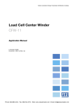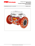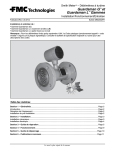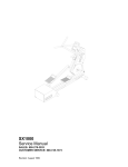
1
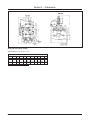
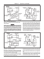
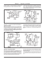
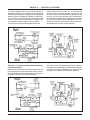
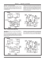
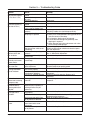
Smith MeterTM Valves
Set Stop
Model 296
Installation/Operation
Issue/Rev. 0.3 (1/03)
Bulletin MN03005
Contents
Section 1 — General .................................................................................................................................. Page 2
Section 2 — Dimensions ........................................................................................................................... Page 3
Section 3 — Specifications ....................................................................................................................... Page 4
Section 4 — Operation ............................................................................................................................... Page 5
Section 5 — Troubleshooting Guide ........................................................................................................ Page 10
Section 6 — Related Publications ............................................................................................................ Page 11
Issue/Rev. 0.3 (1/03)
The Most Trusted Name In Measurement
MN03005 • Page 1
Section 1 — General
This manual has been prepared to acquaint the installer
and serviceman with the operation, adjustment, and maintenance of the basic Smith MeterTM Model 296 Set Stop,
Two-Stage Closure Valves, designed for adaptation of low
flow start with a time delay relay.
These set stop valves are designed to function with
low viscosity products and to operate in conjunction
with Smith meters equipped with set stop counters.
The counter provides a means, by solenoid control, of
reducing flow gradually through the valve, then shutting off accurately after a predetermined quantity of
liquid has passed through the meter.
There is no mechanical linkage between counter and
valve. Remote electrical operation, such as interlocks and
overfill detection, is also made possible with positive control and safety.
In addition to the basic controls which are incorporated with these valves, certain additional control
functions and accessories may be added as required
for the application.
Page 2 • MN03005
The Model 296 Valve is recommended for those installations requiring exact (±0.25 gallon) shut-off delivery of a
determined quantity with a minimum of line shock and
low flow start.
These valves, except for the shape of the valve body, are
identical in general design, application, and performance.
For this reason, except where noted, the valves are treated
as one in this manual. All illustrations are of the 4" Model
296 Valve unless otherwise indicated. Additional information will accompany this manual when accessories
have been added to the basic valve.
These products have been designed for petroleum applications, where corrosion/erosion is normally minimum.
The design of the pressure containing housings have
adequate material allowance for typical petroleum applications. Consult the factory for other applications or for
the actual material allowances.
Issue/Rev. 0.3 (1/03)
Section 2 — Dimensions
Model 296 Valve (Globe Pattern)
Note: All dimensions shown are in inches.
Size
3
4
6
A*
B
11
3
13.50 3.38
17
5.12
C
5
6.31
Model 296 Valve
C1
D
E
F
G
G1
8 14.25 10 9.19 0.25 1.50
8.88 16.38 10.75 10 0.25 1.50
G2
7
7.75
8
10.62 19.50 12.50 11.75 0.25 1.50
9.50
*Class 150 ASME Flanges.
Issue/Rev. 0.3 (1/03)
MN03005 • Page 3
Section 3 — Specifications
Sizes
3", 4", and 6": 296 Series Globe Pattern (cast steel).
End Details
Class 150 ASME B16.5 flanges (cast steel)
Working Pressures
Maximum Working Pressure: 150 psi.
Note:The maximum working pressure is limited by the maximum operating pressure differential rating of the solenoid,
not the system.
Viscosity
Maximum Viscosity at Flowing Temperature: 1,000 SSU
(220 centistokes).
Elastomer/Valve Temperature Limits1
LS (Low Swell) Buna: -20°F to 200°F (-29°C to 93°C).
Buna-N Elastomers: -20°F to 200°F (-29°C to 93°C).
Viton Elastomers: -20°F to 350°F (-29°C to 177°C).
Materials
Main Body and Cover: Cast Steel.
Internals: Ductile iron, bronze, and stainless steel.
Pilots and Control Loop: Steel controls/steel tubing.
Electrical Ratings
120, 240, 480 Vac 60 Hz or 110, 200, 440 Vac 50 Hz.
Optional Equipment Available
Junction Box, Low Flow Start Timer, Rate of Flow Control, Pressure Reducing Control, Back Pressure Control,
others (consult factory or nearest sales office).
Strainer
Diaphragm Type Valve (2 to 6 inch):
1. Valves with a Low Swell Buna, Viton or Buna-N diaphragms and seals: It is recommended that a 4 mesh
or finer strainer be installed upstream of the valve to
ensure minimum maintenance and maximum service
life.
Note: Before starting up a new installation or any system
which has been contaminated with foreign materials (from
repairs, damaged equipment, etc), it is strongly recommended that the following be done:
1.Clean the foreign materials from the line, especially
between the strainer and valve.
2.Install a temporary fine mesh screen (40 mesh or
finer) in the strainer, in order to remove the remaining foreign materials from the system.
Pressure Loss Graphs
It should be noted that these pressure losses are for full
open valves and cannot be used when considering modulating valves, since they rarely go full open during normal
operation. These pressure losses can, however, be used
as guidelines for proper valve sizing.
200 and 200PC Series Pressure Loss
1200 and 1200PC Series Pressure Loss
Flow Data: Valve in wide open position.
Valve cover vented to atmosphere.
Specific gravity 1.0 (water at 60°F).
1 Temperature Limits are based on the following: (a) minimum temperature rating of the housing, (b) min./max. effective temperature of one of the
seals, (c) min/max. temperature limit of typical applications.
Page 4 • MN03005
Issue/Rev. 0.3 (1/03)
Section 4 — Operation
The Model 296 basic Set Stop Valve is complete with all
accessories and controls necessary to provide automatic
two-stage shutdown for a typical loading operation when
used in conjunction with a two-stage set stop counter or
similar device.
The valve is designed to operate in conjunction with a
Model 15A Low Flow Start Timer, a Model 40 Rate of
Flow Control, a Model 50A Pressure Reducing Control, a
Model 60A Back Pressure Control, and others (consult
factory). It is recommended that at least one (1) modulating pilot (such as a rate of flow control) be used to keep
the valve in a modulating condition at all times. This
assures the necessary emergency shutdown response
time, thereby minimizing accidental overruns. This
manual’s principles of operation are based on the 296-40.
The Model 296 basic Set Stop Valve is designed to accomplish the following basic functions:
1. Adequately control the flow to affect an accurate
zero shutoff, without excessive line shock, by utilizing a two-stage shutdown.
2. Limit the flow rate to the meter’s maximum rating by
adding the rate of flow pilot (40A), thus avoiding
meter damage.
3. Limit the downstream pressure by adding the pressure reducing pilot (50A), thus protecting the truck
manifold (bottom loading).
4. Limit the overrun to a safe quantity, guarding against
spills if the emergency shutdown has to be actuated.
The graph, shown below, is a typical loading operation
curve representing the sequence of operation for the 296
Set Stop Valve. Each major control component on the
296 valve is listed down the left side of the chart. The
loading operation curve is divided into 8 zones from left to
right. This will allow a breakdown of the principle of operation into 8 separate zones. Note that the text and examples are based on including the Low Flow Start Timer.
The heavy dark lines indicate energized circuits in the
electrical schematics and high-pressure circuits in the
hydraulic schematics. Dotted lines indicate inter- mediate pressure in the hydraulic schematics.
Installation Note: Entrapped air in the valve cover and/
or control loop can cause the valve to function erratically
and cause severe shocks. Therefore, the air must be
vented from the valve cover and/or the highest point in
the control loop. Open the gate valve only slightly so that
the entire meter run (including the motor and valve) can
slowly fill up with product while the air is vented.
Zone No. 1 - Valve Closed Start-Up Procedure
With the set stop counter in the “off” position and the set
stop counter switches A and B open, the solenoids are
de-energized, pressurizing the valve cover and holding
the valve fully closed.
The closing speed control should initially be opened one
(1) turn, thus assuring that the valve will close quickly
under emergency conditions. Fine-tuning of this control
must be done later, as described in Zone No. 5.
The opening speed control should initially be opened to 1/
2 turn, thus assuring slow opening of the valve, help-
ing to eliminate any severe surprises. Fine-tuning of this
control will be done later, as described in Zone No. 4.
The rate of flow control has been adjusted at the factory
for the flow rate specified on the log sheet, based on
customer specification or maximum rating of meter if
known. Therefore, adjustment at this time is not normally
required. Fine-tuning of this control will be described in
Zone No. 5.
The low flow start timer coil wire should be disconnected
so that all the Zone No. 3 adjustments can be made
without the interference from the timer.
Issue/Rev. 0.3 (1/03)
MN03005 • Page 5
Section 4 — Operation (continued)
Zone 1 — Valve Closed (Model 296-40)
Zone No. 2 - Transition from Valve Closed to Low
Flow Condition
CAUTION
Until the valve is completely under control and functioning correctly, the system should be operated with
only a partially opened butterfly or gate valve upstream of the meter run. This upstream valve should
be opened only enough to allow the necessary flow
rate for the adjustments being made. Only when the
valve has been cycled through the entire sequence,
should the upstream butterfly or gate valve be fully
opened.
Pull out the set stop counter knob which closes the set
stop counter switches A and B. This energizes both solenoids and the low flow start timer coil (now temporarily
disconnected), shutting off the upstream supply of pressure to the valve cover and draining the valve cover downstream through the opening speed control, the rate of
flow control, and the normally closed solenoid pilot valves.
The opening speed control adjustment could be made at
this time if it is required; however, it is recommended that
the fine-tuning be done in Zone No. 4 after observing an
entire valve sequence of operation.
Zone 2 — Transition from Closed to Low Flow Condition (Model 296-40)
Zone No. 3 - Low Flow Condition
When the main valve opens far enough, the stem switch
is actuated, de-energizing the normally closed solenoid
and causing the valve to become hydraulically locked.
The valve cannot open or close at this point.
The stem switch cam should be adjusted to allow the
desired flow rate for the low flow condition. This is achieved
by loosening the nuts on the threaded stem,
Page 6 • MN03005
located on the top of the valve cover, and moving the
cam up or down. Moving the cam up will cause a lower
flow rate. Moving the cam down will cause a higher flow
rate.
Before the low flow start timer coil is reconnected, push
the emergency button on the set stop counter, which
should cause the valve to close. This will prove the valve
can be closed and opened. If the system is a high
Issue/Rev. 0.3 (1/03)
Section 4 — Operation (continued)
pressure system, it may be necessary to readjust the
closing speed control in order to reduce the line shock.
If the closing speed control is readjusted, repeat Zone
Nos. 2 and 3. If everything seems to be operating correctly, reconnect the low flow start timer coil and adjust
the desired low flow time duration.
Zone 3 — Low Flow Condition (Model 296-40)
Zone No. 4 - Transition from Low Flow Condition to
High Flow Condition
When the low flow timer times out, the actuated timer
contacts energize the normally closed solenoid and deenergizes the normally open solenoid. This allows the
valve to open to the high flow condition, at which point the
rate of flow control should start modulating the valve near
the specified flow rate setting.
The opening speed control should be fine tuned at this
point to achieve a smooth transition. If a change in adjustment is made, push the emergency button and repeat
Zone Nos. 2 through 4 for a final opening speed observation.
Zone 4 — Transition from Low Flow Condition to High Flow Condition
Zone No. 5 - High Flow Condition
When the flow rate approaches the specified limit, the
rate of flow control should sense the differential pressure, proportional to the flow, developed across the orifice plate, located in the valve flange. This differential
pressure causes the rate of flow control pilot to start closing, causing a pressure to build up in the cover of
Issue/Rev. 0.3 (1/03)
the valve, forcing the main valve to modulate (or control)
flow rate. A hydraulic balance is then reached, preventing
excessive flow rates.
The closing speed control must be adjusted first because
this adjustment affects the setting of the rate of flow control.
MN03005 • Page 7
Section 4 — Operation (continued)
The closing speed control must be adjusted during an
emergency shutdown. This control must be adjusted to
limit the number of gallons throughput after the high-level
detector signals an emergency shutdown in order to prevent a spill and, at the same time, prevent excessive line
shock. A typical maximum permissible throughput after
an emergency shutdown signal is 18 to 20 gallons.
The rate of flow control should be adjusted after the
closing speed control has been set. It should be fine
tuned to allow the desired specified high flow rate. By
turning the adjustment screw clockwise, the flow rate will
increase. By turning the adjusting screw counter-clockwise, the flow rate will decrease. If adjusting screw reaches
its stop in either direction before desired flow rate is obtained, resizing of the orifice plate may be necessary or,
desired flow rate is beyond system capability.
Zone 5 — High Flow Condition (Modulating Condition Should Exist) (Model 296-40)
Zone No. 6 - Transition from High Flow Condition to
Low Flow Condition
When the set stop counter counts down and actuates the
first stage trip point, the set stop counter switch A opens,
de-energizing the normally closed solenoid and pressurizing the cover of the valve, which initiates the
main valve to close. The speed at which the valve reaches
2nd stage flow is governed by the adjustment made previously for emergency shutdown and should not be
changed for this function of the operation sequence.
Zone 6 — Transition from High to Low Flow Condition (Model 296-40)
Page 8 • MN03005
Issue/Rev. 0.3 (1/03)
Section 4 — Operation (continued)
Zone No. 7 - Low Flow Condition
When the valve reaches the low flow position, the stem
switch is again actuated, closing the switch contact. This
energizes the normally open solenoid and locks the main
valve hydraulically.
A few trials may be necessary if the precise low flow rate
is required. The low flow rate should be approximately the
same flow rate as was set for the low flow start feature in
Zone No. 3 and cannot be changed without also changing the low flow start flow rate. (Refer to Zone No. 3 for
stem switch adjustment.)
Zone 7 — Low Flow Condition (Model 296-40)
Zone No. 8 - Transition from Low Flow Condition to
Valve Closed
When the set stop counter actuates the final stage trip
point, the set stop counter switch B opens. This de-energizes the normally open solenoid and timer coil, fully closes
the main valve, and resets the timer contacts for the next
loading operation.
To obtain an accurate zero shutoff, the set stop counter
cam for the final stage trip point may have to be adjusted.
For this adjustment, refer to the Installation/Operation/
Service Manual for the set stop counter, Bulletin MN01012.
Zone 8 — Transition from Low Flow to Valve Closed (Model 296-40)
Issue/Rev. 0.3 (1/03)
MN03005 • Page 9
Section 5 — Troubleshooting Guide
Problem
Valve does not open.
(No pressure registers
at inlet side of valve.)
Valve does not open.
(Pressure registers at
inlet side of valve.)
Main valve bypasses
low flow start or low
flow shutdown.
Main valve functions
erratically and causes
severe shocks.
Main valve opens too
fast or too slow.
Valve does not go into
1st stage slow down
prior to shutdown.
Product flow decreases too fast during
emergency stop.
Desired high flow rate
is unobtainable by
adjusting 40A rate of
flow pilot.
Valve does not enter
2nd stage of final
shutdown.
Valve does not shut off
at zero.
Page 10 • MN03005
Cause
Upstream shutoff valve is
closed.
Obstruction in upstream shutoff valve.
Pump not operating.
Downstream shutoff valve is
closed.
Differential pressure across
valve is too low (below 5 psi).
Needle valves not adjusted
properly.
Obstruction in pilot or main
diaphragm is ruptured.
No electric power.
Set stop counter switches not
functioning.
Stem switch not operating
properly.
Low flow start timer adjusted
to zero timer.
Entrapped air in the valve
control loop.
Opening speed needle valve
out of adjustment.
Set stop counter handle does
not function properly.
1st trip set stop switch A out of
adjustment or defective.
1st trip N.C. solenoid defective.
Closing speed control is open
too wide.
Desired flow rate is then
beyond system capability, or
resizing of orifice may be
necessary.
Set stop counter not functioning properly.
N.C. solenoid does not open.
2nd trip set stop switch B out
of adjustment or defective.
Low flow rate too fast or too
slow. Stem switch out of
adjustment.
Set stop counter trip cam out
of adjustment.
Remedy
Open shutoff valve.
Remove obstruction.
Start pump.
Open shutoff valve.
Check pressure source for sufficient pressure.
Opening speed control valve should be open. Adjust
sensitivity needle valve (could be open too far).
1. Close the closing speed needle valves.
2. Slowly crack a fifting between closing speed control
and valve cover in cover loop.
3. If valve opens, diaphragm is not ruptured.
4. If continuous flow through fiftings develop, then
diaphragm is ruptured.
5. Close upstream gate valve and remove main valve
cover and replace diaphragm.
Check wiring and power source.
Check set stop counter switches for electrical operation and adjustment.
Check for proper functioning of switch. Refer to Zone
No. 3 - Stem Switch Adjustment.
Adjust timer delay time.
Refer to Zone No. 1, installation note.
Turn adjusting stern on needle valve in clockwise
direction to decrease opening speed.
Refer to Set Stop Counter Bulletin.
Refer to Set Stop Counter Bulletin for
adjustment.
Check for electrical operation. Replace coil if
necessary.
Turn adjusting stem clockwise to decrease rate of
response.
Consult factory or representative.
Refer to Set Stop Counter Bulletin.
Check timer. Solenoid should open. Replacement of
solenoid may be necessary.
Refer to Set Stop Counter Bulletin.
Refer to Zone No. 3 for adjustment.
Refer to Set Stop Counter Bulletin.
Issue/Rev. 0.3 (1/03)
Section 6 — Related Publications
The following literature can be obtained from FMC Technologies Measurement Solutions, Inc. Literature Fulfillment at
[email protected] or online at www.fmctechnologies.com/measurementsolutions. When requesting literature from Literature Fulfillment, please reference the appropriate bulletin number and title.
Parts List (Form No.)*
2" ...................................................................................................................................................................... P1051
3" ...................................................................................................................................................................... P1052
4" ...................................................................................................................................................................... P1053
6" ...................................................................................................................................................................... P1054
*The latest edition is indicated by a 2-digit postscript (e.g., 01, 02, etc.)
Issue/Rev. 0.3 (1/03)
MN03005 • Page 11
Revisions included in MN03005 Issue/Rev. 0.3 (1/03):
Page 2: Added corrosion/erosion note.
Page 4: Removed cast iron option on 3" and 4" sizes. Changed end details from ANSI to ASME. Changed working pressure to 150 psi only.
Modified note to specify differential pressure. Changed temperature ranges, added elastomer LS Buna and footnote 1 and 2.
The specifications contained herein are subject to change without notice and any user of said specifications should verify from the manufacturer that the
specifications are currently in effect. Otherwise, the manufacturer assumes no responsibility for the use of specifications which may have been changed and are
no longer in effect.
Headquarters:
1803 Gears Road, Houston, TX 77067 USA, Phone: 281/260-2190, Fax: 281/260-2191
Gas Measurement Products:
Erie, PA USA Phone 814/898-5000
Thetford, England Phone (44) 1842-82-2900
Kongsberg, Norway Phone (47) 32/286-700
Buenos Aires, Argentina Phone 54 (11) 4312-4736
Integrated Measurement Systems:
Corpus Christi, TX USA Phone 361/289-3400
Kongsberg, Norway Phone (47) 32/286-700
San Juan, Puerto Rico Phone 787/274-3760
United Arab Emirates, Dubai Phone 971 +4/331-3646
Liquid Measurement Products:
Erie, PA USA Phone 814/898-5000
Los Angeles, CA USA Phone 661/702-8660
Slough, England Phone (44) 1753-57-1515
Ellerbek, Germany Phone (49) 4101-3040
Barcelona, Spain Phone (34) 93/201-0989
Moscow, Russia Phone (7) 495/564-8705
Melbourne, Australia Phone (61) 3/9807-2818
Beijing, China Phone (86) 10/6500-2251
Singapore Phone (65) 6861-3011
Chennai, India Phone (91) 44/450-4400
Visit our website at www.fmctechnologies.com
Printed
in U.S.A.
© 1/00 FMC Technologies Measurement Solutions, Inc. All rights reserved. MN03005 Issue/Rev. 0.3 (1/03)
Page 12
• MN03005
Issue/Rev. 0.3 (1/03)