1
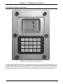
Electronic Preset Delivery System
Smith Meter microLoad.net
Operations Manual
Bulletin MN06149
Issue/Rev. 0.0 (9/04)
The Most Trusted Name in Measurement
Caution
The default or operating values used in this manual and in the program of the microLoad.net
are for factory testing only and should not be construed as default or operating values for your
metering system. Each metering system is unique and each program parameter must be reviewed and programmed for that specific metering system application.
Disclaimer
FMC Measurement Solutions hereby disclaims any and all responsibility for damages, including but not limited to consequential damages, arising out of or related to the inputting of incorrect or improper program or default values entered in connection with the microLoad.net.
Proprietary Notice
This document contains information that is proprietary to FMC Measurement Solutions and is
available solely for customer information. The information herein shall not be duplicated, used,
or disclosed without prior permission of FMC Measurement Solutions.
FMC Measurement Solutions will not be held responsible for loss of liquid or for damage of any
kind or from any cause to the person or property of others, or for loss or profit, or loss of use,
or any other special, incidental, or consequential damages caused by the use or misapplication
of the contents stated herein.
Table of Contents
Section I - Introduction ............................................................................................................................................... 2
Product Description ................................................................................................................................................ 2
How To Use This Manual........................................................................................................................................ 2
Section II - Display and Controls................................................................................................................................ 4
Power Up................................................................................................................................................................ 5
Ready Screen......................................................................................................................................................... 6
Section III - Run Mode ............................................................................................................................................... 7
Overview ................................................................................................................................................................. 8
Remote Start/Stop .................................................................................................................................................. 9
Additive Monitoring ................................................................................................................................................. 9
Section IV - Dynamic Displays................................................................................................................................. 10
System / Live......................................................................................................................................................... 10
Batch Totals / Averages........................................................................................................................................ 11
Transaction ........................................................................................................................................................... 13
Section V - Automated Proving Mode...................................................................................................................... 14
Section VI - Program Mode...................................................................................................................................... 17
Keypad Data Entry ............................................................................................................................................... 17
Entry to Main Directories....................................................................................................................................... 18
Changing Program Mode Parameters ................................................................................................................. 19
Numeric Data .................................................................................................................................................... 19
Alphanumeric Data ........................................................................................................................................... 19
Section VII - Index.................................................................................................................................................... 20
MN06149 Issue/Rev 0.0 (9/04)
1
Section I – Introduction
Product Description
The Smith Meter microLoad.net is a micro-processor based single arm, single product electronic preset instrument that supports up to 12 recipes. It is configurable to support a variety of user applications.
Optimum measurement accuracy is attained through continuous linearization of the meter factor with changes in
flow rates. The microLoad.net is also capable of maintaining back pressure on the measurement system using
automatic flow optimization. Volumetric correction is calculated directly from published API equations providing
precise volumetric measurement results. Precise temperature, pressure compensation (using programmed maintenance pressure), and density correction are options that are available in the instrument.
The dynamic real-time display of the current actual operating conditions of the system provides the operator with
valuable system information while the system is operating.
The microLoad.net provides several loading system control functions: Additive injection, pump control, alarm control, set stop, valve control, back-pressure control, and automatic adjustment of final trip point. Other significant
features are as follows:
•
200 Driver Database
•
Ethernet Connectivity
•
Three Multi-drop Serial Communications Ports
•
Event Logging / Audit Trail
•
User Configurable I/O
•
Three Security Levels
•
Optional Battery Backed Display per OIML
•
Programmable language/messages
•
Automated Proving
•
API Tables from LPG to Crude Oil
How To Use This Manual
This manual is to be used as an operators guide for the microLoad.net.
This manual is divided into five sections: Introduction, RUN Mode, Dynamic Displays, Automated Proving Mode,
Program Mode, and Index.
The "Display and Controls" section describes the microLoad.net’s physical display screen and keypad as well as
some of the basic messages that would initially occur.
The "Run Mode" section describes the typical operation of a microLoad.net.
The "Dynamic Displays" section describes the information that can be displayed by the microLoad.net while in the
"READY" state or in the Run Mode.
2
MN06149 Issue/Rev 0.0 (9/04)
Section I – Introduction
The “Automated Proving Mode” section describes the procedures and events involved in meter proving with a microLoad.net.
The “Program Mode” section describes the mechanics of making configuration changes to a microLoad.net using
the integral display and keypad. See the Reference Manual for details of the parameters that are affected in the
Program Mode.
The “Index” is a comprehensive listing, with page numbers, of all subjects covered in this manual.
The examples presented in this manual are for clarity and operator convenience. The values might vary for specific
installations and/or operations.
MN06149 Issue/Rev 0.0 (9/04)
3
Section II – Display and Controls
microLoad.net Display and Controls
Figure 1. microLoad.net Display and Controls
The user interfaces with the microLoad.net through either through one of its several communications ports or via
the display and keypad found on the face of the instrument. The display and keypad alter their format and function
based upon the mode (Run Mode, Programming Mode….) that the instrument is currently running. The following
provides previews to the various screens as well as the keypad functions associated with the various modes.
4
MN06149 Issue/Rev 0.0 (9/04)
Section II – Display and Controls
Power Up
The following describes the events which occur when the power is applied to a microLoad.net. Upon power up
the microLoad.net goes through a start up sequence. The start up screen will be displayed while a RAM test is
being performed.
FMC
microLoad.net
RAM test
______________
Figure 2. Power Up Screen
Once the start up sequence is complete the microLoad.net will go into its normal operating mode. Depending
upon how the instrument is configured, one of two screens will be seen next. If the microLoad.net does not have
the Powerfail alarm configured the instrument will go directly to the Ready Screen. The Ready Screen is the
launching point for all the microLoad.net functions.
microLoad.net Ready
AAAAAAA
Press SET key
MM/DD/YY HH:MM:SS
Figure 3. Ready Screen
If the Powerfail alarm is configured, the microLoad.net will go to the Powerfail Alarm screen after the start up sequence is completed. It will be necessary for the operator to enter the instrument’s passcode in order to acknowledge the alarm and proceed to the Ready Screen.
Note: The default passcode for the microLoad.net is “0000”.
MN06149 Issue/Rev 0.0 (9/04)
5
Section II – Display and Controls
Ready Screen
The Ready Screen informs the user that the microLoad.net is operating normally and awaiting the user’s input. In
normal day-to-day operation, the driver/operator will be accessing the microLoad’s Run Mode to enter the information required to dispense their loads. The driver initiates the process by depressing the SET key. The microLoad.net will respond with a series of up to five prompts designed to collect information for the transaction to
take place. The number of prompts and their content is defined by Prompt parameters entered into the Communication Directory (761 through 777). The follow is an example of a sequence of prompts.
microLoad.net Ready
Terminal ABC
READY Screen
Press SET key
MM/DD/YY HH:MM:SS
Enter Pin #
Prompt 1
> ____
Press ENTER when done
Enter Driver ID
Prompt 2
> ________
Press ENTER when done
Enter Company Name
Prompt 3
_
Press ENTER when done
Select Recipe
Recipe Select
Screen
Recipe 1
Recipe 2
Recipe X
Enter Preset Amount
> _____XXX
Amount Preset
Screen
Press START when
ready
Valve Opening in
X
Start Countdown
secs
4800
200
IV
GAL
IV
GAL
Batch #1 - Recipe 2
150 GPM - P500
RUN Screen
Figure 4. Typical Prompt Sequence
6
MN06149 Issue/Rev 0.0 (9/04)
Section III – Run Mode
Run Mode
The Run Mode is the normal driver-controlled mode of operation where a preset volume of product is entered into
the microLoad.net. The flow is then initiated, controlled, and stopped by the microLoad.net at the end of the batch.
All preset and control operations can be performed either locally through the keypad or through communications.
The operation described in this section assumes that the microLoad.net is being operated locally through the keypad. For information on operating through communications, refer to the microLoad.net Communications and Reference Manuals.
Keypad Functions
The pushbuttons on the keypad perform the following preset functions in the Run Mode:
0-9
Used for entering numeric data
CLEAR
Used to clear incorrect entries and to exit from the dynamic displays
ENTER
Used for dynamic displays and selecting the recipe to be loaded
PRINT
Signals completion of transaction
SET
Used to initiate the preset sequence
START
Used to start the delivery (providing all external permissive senses are satisfied)
STOP
Used to stop delivery at any time (not intended as emergency stop)
↑
Used to move the selection arrow up in selection of recipes and navigating the dynamic displays
↓
Used to move the selection arrow down in selection of recipes and navigating the
dynamic displays
←→
Not Used
F1
Not Used
F2
Not Used
7
MN06149 Issue/Rev 0.0 (9/04)
Section III – Run Mode
Overview
The "RUN" Mode permits the operator to select the recipe and preset volume, start the preset volume, and observe the dynamic variables such as flow rate, temperature, volume correction factors, transaction totals and nonresettable totals. The microLoad.net processes normal start-up, flow control and shutdown sequences, and operator-requested stops.
Product delivery is controlled by several program code entries. Functions such as first high flow rate, second high
flow rate, low flow start, and first and second trip points are automatically controlled and monitored per their program
entries. Safety and volume accuracy functions including excess high flow, low flow, overrun, and temperature probe
failure are also monitored per their program parameters. If at any time, an alarm occurs while in the Ready State or
the Run Mode, the microLoad.net will attempt to shut down the flow and a message indicating an alarm condition will
pop up over the current display.
At the end of the delivery, the "batch complete" message will flash at the bottom of the RUN screen.
4800
4800
IV
GAL
IV
GAL
Batch #1 - Recipe 2
Batch Complete
Depending on how the microLoad.net is programmed, a transaction can be ended by pressing the "PRINT" button,
by a communication command, or by an external input.
If the "STOP" button is pressed during flow, and if the Start after Stop delay is programmed, the preset position will
display:
Restart in
X
secs
Once the time-out has been reached, the display will flash "Batch Stopped".
4800
200
IV
GAL
IV
GAL
Batch #1 - Recipe 2
Batch Stopped
The operator can then press "START" and continue the batch or “PRINT” to terminate the batch. If the operator
elects to continue the batch the microLoad.net will countdown to valve reopening and then return to the RUN screen.
8
MN06149 Issue/Rev. 0.0 (9/04)
Section III – Run Mode
Remote Start/Stop
Digital inputs can be programmed to be used for Remote Start/Remote Stop operations. When the power is applied to these contacts, the microLoad.net will respond as though the "START" or "STOP" keys have been
pressed on the keypad.
Additive Monitoring
Additive injector feedback provides the capability of the microLoad.net monitoring the additive products that are
being injected. The microLoad.net monitors the injector feedback switches for a change of state and counts the
errors if no change is detected before the next injection. An alarm will be set if the number of errors exceeds the
programmable maximum.
With Smart or metered injectors, the additive volume injected is actually measured, providing the ultimate in feedback. The microLoad.net communicates with the Additive Injector System where the microLoad.net is the master.
The microLoad.net constantly monitors the Additive System for its status, polls for additive totals, and signals the
system when to inject the additive – all through the communications line.
The microLoad.net communications package has also been designed with a pass-through communications mode. In
this mode of operation, the supervisory computer can talk to the Additive Injector System through the communication
lines that have been run to the microLoad.net and from the microLoad.net to the Additive Injector System(s). (This is
further described in the microLoad.net Communications Manual.)
microLoad.net interfaces with smart additive injector systems. A system may incorporate one metered injector along
with digital outputs to energize additive pumps and injector solenoids.
MN06149 Issue/Rev 0.0 (9/04)
9
Section IV – Dynamic Displays
Dynamic Displays
While in the RUN mode the user may review both live and stored data held in the microLoad.net. The ENTER key is
used to switch to the Dynamic Displays page. (The CLEAR key will return to the RUN screen.)
Dynamic Displays
System/Live
Batch Totals/Avgs
Transaction
Diagnostics
There are four groups of dynamic display data available to the user. The “System/Live” data is related to the active
data gathered at the time of inquiry. The Batch Totals/Avgs is total and average data for the current or past batches.
The Transaction data is related to the ongoing transaction. Dynamic Diagnostics is covered in the microLoad.net
Service Manual.
Keypad Functions
The keys on the keypad perform the following functions when accessing the dynamic displays:
0–9
Used to enter the desired batch number on batch dynamic displays, etc.
↑
Used to navigate backwards through the menu to get into the displays. When in the
dynamic displays, the up arrow also moves backward through the displays.
←
Once in the dynamic displays, this works like the up arrow to move backwards
through the displays
→
Once in the dynamic displays, this works like the down arrow to move forward
through the displays
↓
Used to navigate forward through the menu to get into the displays. When in the dynamic displays, the down arrow also moves forward through the displays.
CLEAR
Used to exit the dynamic display
ENTER
Used to enter the Dynamic Display menu and to enter the dynamic displays from the
menu
10
MN06149 Issue/Rev 0.0 (9/04)
Section IV – Dynamic Displays
System / Live
The System / Live data appears on several screens which are accessible using the UP and DOWN ARROW keys.
The information includes: Flowrate (/minute), Flowrate (/hour), Recipe #, Preset Amount, Amount Remaining, Meter
Factor, Temperature, Density, Pressure, Additive Presets, Valve Position, Date and Time of last power failure.
Flowrate in amount/minute
XXXXX.X Gal/Mn
XXXXX.X Gal/Hr
Recipe #
Preset
XXXXX
Flowrate in amont/hour
Current Recipe Designation
Preset Amount
Amount yet to be Delivered
Remain XXXXX
Mfac
X.XXXXX
Temp
XX.X
Den
XXXXX
Meter Factor
Temperature
Density
Pressure
Pres
XX.X
A1 P XXX C XXX
Valve Req. AAAAA
PF Date MM/DD/YY
Additive 1 Preset & Current Amount
Valve Request (Open, Close, Lock)
Date of last Power Failure
Time of Last Power Failure
PF Time HH:MM:SS
Figure 5. System/Live Screens
Batch Totals/Avgs
The microLoad.net will requires the operator to select which batch data is to be viewed. Simply pressing the ENTER key will provide the current data.
Batch Totals/Avgs
Select Batch
> ___
Press ENTER for
current or last
batch
The data provided includes the various volume types (i.e. IV, GV, GST, GSV), Mass, Meter Factor, Temperature,
Density, Pressure, Vapor Pressure, CTL, CPL, and Additive Amount.
MN06149 Issue/Rev 0.0 (9/04)
11
Section IV – Dynamic Displays
Batch Totals / Avgs
Batch Totals/Avgs
Select Batch
> ___
Press ENTER for
current or last
batch
Recipe #
IV
XXXX.X
GV
XXXX.X
GST
XXXX.X
Batch #X more
GSV
XXXX.X
Mass
XXXX.X
MFac
X.XXXXX
Temp
XX.X
Batch #X more
Recipe Designation
Indicated (Raw) Volume
Gross Volume
Gross Volume at Standard
Temperature
Gross Volume at Standard
Temperature and Pressure
Mass Total
Meter Factor
Temperature
Den
XXXX.X
Pres
XX.X
VPres
X.X
D@RT
XX.X
Batch #X more
D@RT
XX.X
Rel D@RT X.XXX
CTL
X.XXX
CPL
X.XXX
Batch #X more
Density
Pressure
Vapor Pressure
Density @ Reference
Temperature (API)
Density @ Reference
Temperature (Mass/Vol)
Relative Density @
Reference Temperature
Temperature Correction Factor
Pressure Correction Factor
Add X
X.XXX
Additive Amount
Batch #X more
Figure 6. Batch Totals/Averages
12
MN06149 Issue/Rev. 0.0 (9/04)
Section IV – Dynamic Displays
Transaction
The transaction data provided includes the various volume types (i.e. IV, GV, GST, GSV), Mass, Temperature,
Density, Pressure, Meter Factor, CTL, CPL, and Additive Amount.
Indicated (Raw) Volume
IV
XXXX.X
GV
XXXX.X
GST
XXXX.X
GSV
XXXX.X
Transaction more
Gross Volume
Gross Volume at Standard
Temperature
Gross Volume at Standard
Temperature & Pressure
Mass Total
Mass
XXXX.X
Temp
XX.X
Den
XX.X
Pres
XX.X
Transaction more
Temperature
Density
Pressure
Meter Factor
MFac
X.XXXXX
CTL
X.XXXX
CPL
X.XXXX
Add X
X.XXX
Transaction more
Temperature Correction Factor
Pressure Correction Factor
Additive X Amount
Figure 7. Transaction Display
MN06149 Issue/Rev 0.0 (9/04)
13
Section V – Automated Proving Mode
Automated Proving Mode
The microLoad.net firmware provides an automated proving mode of operation. This feature allows the operator
to prove the meter and update meter factors and associated flow rates without having to enter the program mode.
When the automated proving mode is activated, the microLoad.net will calculate the meter factor for a proving run
based on information that is obtained during the prove. The operator can select the flow rate and associated meter factor that is being proved through the keypad of the microLoad.net. After the prove is complete, the operator
enters the prover volume and prover temperature and the microLoad.net calculates the new meter factor. The operator has the choice of accepting the new meter factor or ignoring it. The microLoad.net also has the capability of
providing an average meter factor over a maximum of ten proves.
Entry to the Automated Proving Mode will require several conditions to be met.
1.
The Automated Proving Mode must be enabled via “Volume Accuracy, Auto Prove Select”, parameter 331.
This parameter is used to enable or disable the Automated Proving Mode. The default for this program code
will be disabled. Select one of the two (2) security options to enable the automated prove and associated security. Once selected and the security activated, the beginning of the next transaction will launch the auto
prove.
2.
The counters must be set to the proving mode through “Volume Accuracy, Proving Counters”, parameter 332.
In this mode the microLoad.net operates as in the Run Mode, except the preset and delivery counters both
count up and go to tenths resolution. Volume preset and delivery units are in the volume units selected in the
display units select code. The factory default is "Not Proving."
3.
The programmed security must be met. When normal conditions are met for starting a transaction (pressing
the "SET" key or receiving authorization via communications), the Automated Proving Mode will be activated.
After the microLoad.net has gone through the user programmed prompts (see Figure 4) the will display the
question “Are You Proving?”. If the user indicates NO, the balance of the preset sequence will continue as if
a normal load. If the user answers YES, the automated proving sequence continues.
4.
To initiate the proving sequence, the microLoad.net will prompt for the prover volumetric coefficient of expansion. Note that the most recent value for this entry will be displayed. If this value is acceptable, the operator
need only press "ENTER."
5. The microLoad.net will prompt for the low flow start volume. If low flow start is not desired, enter zero. Press
"ENTER."
6.
Next, the microLoad.net will display the "Select Recipe" prompt. If in remote control communications mode,
only those recipes allocated will be available for selection. Recipes must be selected before the meter factors,
since the recipe determines the product being proved. Using the up and down arrow keys, select the required
recipe.
7.
The operator must next select the meter factor and associated flow rate for proving.
Move the up or down arrow keys to the meter factor associated flow rate that is required. Note that only those factors currently programmed will be offered as selections. Press ENTER after entering the selection.
8.
Enter the batch amount desired.
9.
Press "START" to begin flow. The flow rate associated with the selected meter factor will be used as the high
flow rate. The batch will be delivered. The flow rate ramp-down from first trip to the end of the batch will be
the same as if not proving.
14
MN06149 Issue/Rev 0.0 (9/04)
Section V – Automated Proving Mode
Are You Proving?
No
Yes
Enter Prover
Coefficient
1.000000000
Date
Time
Enter Low Flow
Start Amount
----- Gal
Date
Time
Select Recipe
Recipe 1
Recipe 2
Select Meter Factor
to Prove
#1 1.XXXX XXGPM
#2 1.XXXX XXGPM
#3 1.XXXX XXGPM
Recipe X
Enter Preset
Amount
_____ Gal
Press START when
ready
Figure 8. Prove Setup
10. When the batch has completed, the microLoad.net will prompt for the actual prover volume. Enter the prover
volume and press "ENTER."
11. The microLoad.net will prompt for the prover temperature. Press ENTER to have the meter factor calculated.
12. The microLoad.net will then calculate the meter factor. The new meter factor will be displayed.
MN06149 Issue/Rev 0.0 (9/04)
15
Section V – Automated Proving Mode
13. When the ENTER key is pressed, the microLoad.net will display the following screen.
14. If "REJECT" or "SAVE" is selected, the microLoad.net will return to the Run Mode display where the transaction can be ended. If "AVERAGE" is selected, the microLoad.net will then average all meter factors in the
buffer (up to ten of them). The average meter factor will be displayed. Select "SAVE" to download the average meter factor into the Program Mode.
15. If "Save" is selected, the microLoad.net will download the average meter factor and will return to the "RUN"
mode display where the transaction can be ended or a new batch can be started. If "Continue" is selected, a
new batch can be started allowing the microLoad.net to continue proving at this rate. Note that if the microLoad.net is in remote control mode, authorization is required for each batch.
R a w M e te r A m o u n t
X X X .X X G a l
E n te r P ro v e r A m o u n t
_______ G al
B a tc h C o m p le te
M e te r T e m p e ra tu re
X X .X F
E n te r P ro v e r T e m p .
_______ F
B a tc h C o m p le te
# X 1 .X X X X X X G P M
N e w M e te r F a c to r
X X X .X X X X X
A v g F lo w ra te X X X G P M
P re s s E N T E R to
c o n tin u e
N e w M e te r F a c to r
X X X .X X X X X
R e je c t
Save
A v e ra g e
R e -e n te r d a ta
Figure 9. Prove Data
16. In the event that the meter factor is not successfully downloaded, the microLoad.net will display a message
indicating that the meter factor was rejected.
16
MN06149 Issue/Rev. 0.0 (9/04)
Section VI – Program Mode
Program Mode
The microLoad.net has a significant number of customizable features which are selectable by the user. The process
of selecting these features and customizing the microLoad.net to each application is performed in the Program
Mode. All programming information is entered via the keypad or through communications. This section will describe the procedure for entering via the keypad. The program codes for microLoad.net are divided into several
main directories plus Diagnostics. The main directories and their contents are discussed in detail in the microLoad.net Reference Manual.
Keypad Data Entry
The pushbuttons on the keypad perform the following functions while the instrument is in the Program Mode:
0–9
Used to enter the access code and for data entries
CLEAR
Used for clearing incorrect entries or for getting to an exit point
ENTER
Used to enter the Program Mode security access code, to enter the subdirectory,
and to enter program data
START
Not used in Program Mode
SET
Page scrolling
PRINT
Used to access Help Messages
STOP
Used to set the security level
F1
Not used in Program Mode
F2
Not used in Program Mode
↑
Used to move up through the menus and rows for alphanumeric entries
↓
Used to move down through the menus and rows for alphanumeric entries
+/-
Used for adding signs to values being programmed
.
Decimal point, for values requiring one
← →
Used for alphanumeric entries
17
MN06149 Issue/Rev 0.0 (9/04)
Section VI – Program Mode
Entry to Main Directories
1.
Assert the security input if configured. This will provide the first step for access to program codes.
microLoad.net Ready
AAAAAAA
Press SET key
MM/DD/YY HH:MM:SS
2. Press "ENTER." This displays the main menu.
microLoad.net Ready
XXXXXXXX
Press SET key
MM/DD/YY H:MM:SS PM
Main Menu
Dynamic Displays
Print Menu
Program Mode Menu
Diagnostics Menu
Figure 10. Accessing Main Menu
3.
Move the arrow to the Program Mode menu and press "ENTER." This will display the "Enter Passcode" screen.
4.
Enter the access code. (The access code preset at the factory is "0".) For security, any digit entered will be
displayed as an "X". (Access codes can be up to four digits long.)
5.
Press "ENTER." This procedure checks for the proper access code. If it is correct, the following will be
displayed.
6. If an incorrect access code was entered, an “Access Denied, CLEAR = re-enter” message will appear. Press
CLEAR to return the display to the "Enter Passcode Screen" in Step 3. Repeat Steps 3, 4, and 5 to re-enter
Program Mode.
Figure 11. Opening Program Mode
18
MN06149 Issue/Rev. 0.0 (9/04)
Section VI – Program Mode
Changing Program Mode Parameters
The program codes represent parameters that can be changed either to enhance the performance of the microLoad.net or to accommodate application changes. There are three types of parameters in microLoad.net:
codes that require numerical data, codes where an option can be selected from a list, and codes where alphanumeric data is entered. Once a code has been selected, change the programmed contents by entering a new value
through the keypad.
Numeric Data
The numeric data is entered into the program codes via the keypad just as numbers are entered into a calculator.
The number of digits for each entry is listed in the Reference section of this manual.
Alphanumeric Data
The parameters that require alphanumeric data are the codes that display Product Messages, Prompt Messages,
or Permissive Messages on the displays of microLoad.net, or provide information to be printed out on the Bill of
Lading Emulation. When adding or changing information in these alphanumeric program codes, the keys listed
below perform the following functions.
Key
Description
ENTER
Moves the character from the character set to the ID line. Also enters the data into the
instrument's memory after END has been selected from the character set
SET
Moves the cursor six positions to the right
→
Moves the cursor one position to the right each time it is pressed
←
Moves the cursor one position to the left each time it is pressed
↑ and ↓
Selects the next block of characters. An example of this is changing from uppercase
letters to lowercase letters. The blocks of characters available in microLoad.net are as
follows:
•
•
•
ABCDEFGHIJKLMNOPQRSTUVWXYZ#*
abcdefghijklmnopqrstuvwxyz&@
0 1 2 3 4 5 6 7 8 9 < > ( ) ? ! . ,' - " / + = _ END
MN06149 Issue/Rev 0.0 (9/04)
19
Section VII – Index
A
Access code, 17, 18
Arrow keys, 9, 13, 19
Automated Proving Mode, 16, 17, 18
B
Batch, 7, 8, 10, 11, 12, 14, 15, 16
Batch Totals / Averages, 13, 14
C
CLEAR, 9, 13, 19
D
Display, 6, 7, 8
Dynamic Displays, 4, 13, 14, 15
E
ENTER, 9, 13, 19
Exit without saving, 22
F
F1, 9, 13, 19
F2, 9, 13, 19
G
H
I
K
Keypad, 9, 13, 19
L
M
Main Menu, 20
Meter factor, 1, 9, 10, 11, 13, 14, 15, 16
20
MN06149 Issue/Rev 0.0 (9/04)
Section VII – Index
N
O
Overview, 10
P
Parameter, 3, 6, 8, 14, 18, 19
Passcode, 5, 18
Powerfail, 7, 12, 13
PRINT, 9, 13, 19
Program code, 8, 14, 17, 18, 19
Program Mode, 2, 3, 14, 16, 17, 18, 20
Prompt Messages, 8
Prove, 14, 15, 16
R
Ready Screen, 7, 8, 20
Run Mode, 2, 4, 6, 7, 8, 10, 14, 16
S
SET, 9, 13, 19
START, 9, 13, 19
STOP, 9, 13, 19
System / Live, 12, 13
T
Temperature, 2, 8, 10, 11, 13, 14, 15
Transaction, 6, 7, 8, 10, 13, 14, 16
U
V
W
Z
MN06149 Issue/Rev 0.0 (9/04)
21
Section VIII – Related Publications
The following literature can be obtained from FMC Measurement Solutions Literature Fulfillment at
[email protected] or online at www.fmcmeasurementsolutions.com. When requesting literature from Literature
Fulfillment, please reference the appropriate bulletin number and title.
microLoad.net
Specification.......................................................................................................................... Bulletin SS06045
Installation ............................................................................................................................. Bulletin MN06150
microLoad.net Operator Reference ...................................................................................... Bulletin MN06148
Communications ................................................................................................................... Bulletin MN06147
Service .................................................................................................................................. Bulletin MN06151
The specifications contained herein are subject to change without notice and any user of said specifications should verify from the manufacturer that the specifications are currently in effect. Otherwise, the manufacturer assumes no responsibility for the use of specifications which may have been changed and are no longer in effect.
Headquarters:
1803 Gears Road, Houston, TX 77067 USA, Phone: 281/260-2190, Fax: 281/260-2191
Gas Measurement Products:
Houston, TX USA Phone 281/260-2190
Thetford, England Phone (44) 1842-82-2900
Kongsberg, Norway Phone (47) 32/286-700
Buenos Aires, Argentina Phone 54 (11) 4312-4736
Liquid Measurement Products:
Erie, PA USA Phone 814/898-5000
Los Angeles, CA USA Phone 661/702-8660
Slough, England Phone (44) 1753-57-1515
Ellerbek, Germany Phone (49) 4101-3040
Barcelona, Spain Phone (34) 93/201-0989
Integrated Measurement Systems:
Corpus Christi, TX USA Phone 361/289-3400
Kongsberg, Norway Phone (47) 32/286-700
San Juan, Puerto Rico Phone 787/274-3760
United Arab Emirates, Dubai Phone 971 +4/331-3646
Visit our Web site at www.fmcmeasurementsolutions.com
Printed in U.S.A. © 9/04 FMC Measurement Solutions. All rights reserved. MN06149 Issue/Rev. 0.0 (9/04)
Moscow, Russia Phone (7) 095/564-8705
Melbourne, Australia Phone (61) 3/9807-2818
Beijing, China Phone (86) 10/6500-2251
Singapore Phone (65) 6861-3011
Chennai, India Phone (91) 44/450-4400