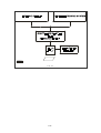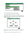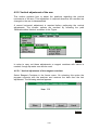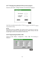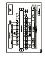
1
SERVICE MANUAL MS370IB170203 I II CONTENTS 1. INTRODUCTION ................................................................................... 1-1 2. DESCRIPTION OF THE INSTRUMENT SYSTEMS.............................. 2-1 2.1. General description of the analyzer ........................................... 2-1 2.1.1. Liquid processing system ............................................... 2-2 2.1.1.1. Well selector ................................................... 2-3 2.1.1.2. Pipetting systems ............................................ 2-3 2.1.2. Reading group ................................................................ 2-4 2.1.3. Electronic and communications control .......................... 2-4 2.1.4. Application program........................................................ 2-4 2.2. Description of the elements........................................................ 2-5 2.2.1. Rotor gear....................................................................... 2-5 2.2.1.1. Constituent elements ...................................... 2-5 2.2.1.2. Description of the system................................ 2-5 2.2.2. Pre-warming of the reaction wells................................... 2-6 2.2.2.1. Constituent elements ...................................... 2-6 2.2.2.2. Description of the system................................ 2-6 2.2.3. Dosifier............................................................................ 2-7 2.2.3.1. Constituent elements ...................................... 2-7 2.2.3.2. Description of the system................................ 2-7 2.2.4. Transfer arm ................................................................... 2-8 2.2.4.1. Constituent elements ...................................... 2-8 2.2.4.2. Description of the system................................ 2-9 2.2.5. Sipping system............................................................... 2-11 2.2.5.1. Constituent elements ..................................... 2-11 2.2.5.2. Description of the system............................... 2-12 2.2.5.3. Control parameters ........................................ 2-12 2.2.6. Thermostating system.................................................... 2-12 2.2.6.1. Constituent elements ..................................... 2-13 2.2.6.2. Description of the system............................... 2-13 2.2.7. Optical system ............................................................... 2-13 2.2.7.1. Constituent elements ..................................... 2-14 2.2.7.2. Description of the system............................... 2-14 2.2.7.3. Signal treatment ............................................. 2-14 2.2.8. Communications ............................................................ 2-15 2.2.8.1. Channel type .................................................. 2-15 2.2.8.2. Channel characteristics.................................. 2-15 2.2.8.3. Transmitted information and handshakes ...... 2-15 2.2.8.4. Programming.................................................. 2-16 Figures ............................................................................................. 2-17 I 3. ELECTRONIC CIRCUIT ........................................................................ 3-1 3.1. Block diagram............................................................................. 3-1 3.1.1. Microprocessor ............................................................... 3-1 3.1.2. Control of the lamp ......................................................... 3-1 3.1.3. Filter-wheel detection circuit ........................................... 3-1 3.1.4. Control of the filter wheel motor...................................... 3-1 3.1.5. Multiplexer amplifier of the temperature sensors............ 3-1 3.1.6. Control of the Peltier cell ................................................ 3-1 Block Diagram........................................................................... 3-2 3.1.7. Control of the peristaltic pump motor .............................. 3-3 3.1.8. Logarithmic amplifier....................................................... 3-3 3.1.9. Analogic-digital converter ............................................... 3-3 3.1.10. Control of the rotor motor.............................................. 3-3 3.1.11. Detector of the departing position of the rotor .............. 3-3 3.1.12. Control of the pre-warming device of the reaction wells3-3 3.1.13. Control of the arm vertical motor................................... 3-3 3.1.14. Control of the arm rotation motor .................................. 3-4 3.1.15. Detector or the vertical departing position of the arm... 3-4 3.1.16. Detector of the departing position of the arm rotation... 3-4 3.1.17. Detector of vertical blocking of the arm ........................ 3-4 3.1.18. Detector of angular blocking of the arm........................ 3-4 3.1.19. Control of the pre-warming device of the reagent......... 3-4 3.1.20. Detector of the liquid level ............................................ 3-4 3.1.21. Control of the syringe motor ......................................... 3-5 3.1.22. Detector of the syringe departing position .................... 3-5 3.1.23. Control of the solenoid valve of the dosifier.................. 3-5 3.1.24. Control of the fans ........................................................ 3-5 3.1.25. Keyboard circuit ............................................................ 3-5 3.1.26. Display circuit ............................................................... 3-5 3.1.27. Power supply ................................................................ 3-5 3.1.28. RS-232 communications channel ................................. 3-6 3.1.29. Reset circuit and control of the battery ......................... 3-6 3.2. Electronic circuit description ...................................................... 3-6 3.2.1. Microprocessor ............................................................... 3-6 3.2.2. Control of the lamp ......................................................... 3-7 3.2.3. Filter wheel detector circuit............................................. 3-7 3.2.4. Control of the filter wheel motor...................................... 3-8 3.2.5. Multiplexer amplifier of the temperature sensors............ 3-8 3.2.6. Control of the Peltier cell ................................................ 3-9 3.2.7. Control of the peristaltic pump motor .............................. 3-9 3.2.8. Logarithmic amplifier...................................................... 3-10 3.2.9. Analogic-digital converter .............................................. 3-10 3.2.10. Control of the rotor motor............................................. 3-10 3.2.11. Detector of the departing position of the rotor ............. 3-11 II 3.2.12. Control of the pre-warming device of the reaction wells.............. 3-11 3.2.13. Control of the arm vertical motor.................................. 3-11 3.2.14. Control of the arm rotation motor ................................. 3-12 3.2.15. Detector of the vertical departing position of the arm .. 3-12 3.2.16. Detector of the departing position of the arm rotation.. 3-12 3.2.17. Detector of the vertical blocking of the arm ................. 3-13 3.2.18. Detector of angular blocking of the arm....................... 3-13 3.2.19. Control of the pre-warming device of the reagent........ 3-13 3.2.20. Detector of the liquid level ........................................... 3-14 3.2.21. Control of the syringe motor ........................................ 3-14 3.2.22. Detector of the syringe departing position ................... 3-14 3.2.23. Control of the solenoid valve of the dosifier................. 3-15 3.2.24. Control of the fans ....................................................... 3-15 3.2.25. Keiboard circuit ............................................................ 3-15 3.2.26. Dsplay circuit ............................................................... 3-16 3.2.27. Power supply ............................................................... 3-16 3.2.28. RCS-232 communications channel.............................. 3-17 3.2.29. Reset circuit and control of the battery ........................ 3-17 4. ADJUSTMENTS AND CHECKS ........................................................... 4-1 4.1. Description of the service program ............................................ 4-1 4.2. Adjustments................................................................................ 4-2 4.2.1. Photometric adjustment .................................................. 4-2 4.2.2. Adjustment of the flow-thru cell thermostating system.... 4-5 4.2.3. Adjustment of the rotor pre-warming system................... 4-6 4.2.4. Horizontal adjustment of the arm .................................... 4-8 4.2.4.1. Horizontal adjustment of the reagent containers........................................................ 4-9 4.2.4.2. Horizontal adjustment of the washing unit ...... 4-9 4.2.4.3. Horizontal adjustment of the reaction wells.... 4-10 4.2.4.4. Horizontal adjustment of the sample wells of the inner ring .................................................. 4-12 4.2.4.5. Horizontal adjustment of the sample wells of the middle ring................................................ 4-13 4.2.4.6. Horizontal adjustment of the sample wells of the outer ring .................................................. 4-13 4.2.5. Vertical adjustment of the arm ....................................... 4-14 4.2.5.1. Vertical adjustment of the reagent container.. 4-14 4.2.5.2. Vertical adjustment of the reaction wells........ 4-15 4.2.5.3. Vertical adjustment of the washing unit.......... 4-16 4.2.5.4. Vertical adjustment of the sample wells ......... 4-17 4.2.6. Adjustment of the peristaltic pump ................................. 4-19 4.2.7. Adjustment of the position of the syringe ....................... 4-20 4.2.8. Adjustment of the position of the filters wheel................ 4-21 III 4.3. Checks ...................................................................................... 4-22 4.3.1. Motors Test .................................................................... 4-22 4.3.1.1. Test of the arm motor (vertical movement)....... 4-22 4.3.1.2. Test of the arm motor (horizontal movement) .. 4-23 4.3.1.3. Test of the peristaltic pump motor .................... 4-24 4.3.1.4. Test of the filter wheel motor ............................ 4-25 4.3.1.5. Test of the rotor motor...................................... 4-25 4.3.1.6. Test of the syringe motor.................................. 4-26 4.3.2. Test of the electrovalve.................................................. 4-26 4.3.3. Test of the vertical impact detector................................ 4-27 4.3.4. Test of the liquid detector .............................................. 4-28 4.3.5. Test of the Peltier temperature ...................................... 4-29 4.3.6. Test of the rotor temperature ......................................... 4-29 4.3.7. Test of the arm pre-heater temperature......................... 4-30 4.3.8. Tests of the photometry ................................................. 4-30 4.3.8.1. Filters sensitivity test........................................ 4-31 4.3.8.2. Absorbance reading test .................................. 4-31 4.3.8.2.1. Test using neutral filters ................... 4-32 4.3.8.2.2. Test using solutions.......................... 4-32 4.3.8.3. Noise test ......................................................... 4-33 4.4. Utilities ...................................................................................... 4-34 4.4.1. Printing of the settings ................................................... 4-35 4.4.2. Printing of the tests results ............................................ 4-35 4.4.3. Programming the serial number of the instrument ......... 4-35 4.4.4. Programming the name of the operator ......................... 4-36 4.4.5. Priming of the circuits .................................................... 4-36 4.4.6. Washing of the circuits .................................................. 4-36 4.4.7. Changing the password of the service program ............ 4-37 4.4.8. Programming the filters table ......................................... 4-37 4.4.9. Programming the communications................................. 4-38 5. CHANGE OF THE PROGRAM IN THE FLASH MEMORY ................... 5-1 5.1. Saving of the old version............................................................ 5-1 5.2. Loading the new version ............................................................ 5-3 6. MAINTENANCE AND CARE................................................................. 6-1 6.1. Maintenance............................................................................... 6-1 6.1.1. Disassembling the transfer arm ...................................... 6-1 6.1.2. Changing the casing ....................................................... 6-1 6.1.3. Changing the main board ............................................... 6-2 6.1.4. Changing the display board ............................................ 6-2 IV 6.1.5. Changing the keyboard................................................... 6-3 6.1.6. Changing the transformer ............................................... 6-3 6.1.7. Removing the cuvette holder tray ................................... 6-3 6.1.8. Changing the filter wheel ................................................ 6-4 6.1.9. Changing the filter wheel motor ...................................... 6-4 6.1.10. Changing the peristaltic pump ...................................... 6-5 6.1.11. Changing the Peltier cell............................................... 6-5 6.1.12. Changing the photodiode.............................................. 6-6 6.1.13. Changing the fan .......................................................... 6-7 6.1.14. Changing the temperature probe .................................. 6-7 6.1.15. Changing the lamp........................................................ 6-7 6.1.16. Changing a filter ........................................................... 6-8 6.1.17. Changing the lenses ..................................................... 6-9 6.1.18. Changing the transfer arm vertical motor...................... 6-9 6.1.19. Changing the transfer arm rotation motor .................... 6-10 6.1.20. Changing the rotor motor ............................................. 6-11 6.1.21. Changing the dosifier motor......................................... 6-11 6.1.22. Changing the program ................................................. 6-12 6.1.23. Changing the pre-warming device of the reaction wells ............. 6-12 6.1.24. Changing the safety spring .......................................... 6-13 6.1.25. Changing the needle set.............................................. 6-13 6.1.26. Changing the pre-warming device of the reagent ........ 6-14 6.1.27. Changing the water filter.............................................. 6-14 6.2. Care and cleaning ..................................................................... 6-14 6.2.1. General care of the analyzer ......................................... 6-14 6.2.2. Cleaning of the optical components............................... 6-15 6.2.3. Cleaning of the filters..................................................... 6-16 6.2.4. Cleaning of the lenses ................................................... 6-16 6.2.5. Cleaning of the photodiode............................................ 6-16 6.2.6. Cleaning of the liquid processing circuits ...................... 6-16 6.2.7. Cleaning of the flow-thru cuvette ................................... 6-16 6.2.8. General cleaning of the instrument................................ 6-17 6.3. Preventive maintenance............................................................ 6-18 Figures ............................................................................................. 6-19 APPENDIX I.: SUMMARY OF TECHNICAL SPECIFICATIONS ............... I-1 APPENDIX II: ADJUSTMENTS TOLERANCES TABLES ........................ II-1 II.1. Main voltage measurement points ............................................. II-1 II.2. Photometric calibration tolerances ............................................. II-1 II.3. Sensitivity filters with flow cuvette .............................................. II-2 V II.4. Arm mechanic adjustments tolerances....................................... II-2 II.5. Flow cuvette thermostat adjustment ........................................... II-2 II.6. Rotor thermostat adjustment ...................................................... II-2 II.7. Peristaltic pump adjustment ....................................................... II-3 II.8. Syringe adjustment..................................................................... II-3 II.9. Filters wheel adjustement........................................................... II-3 II.10 Electric Noise ............................................................................ II-3 APPENDIX III: ACCESSORIES AND SPARE PARTS ............................. III-1 III.1. Accessories list ........................................................................ III-1 III.2. Spare parts............................................................................... III-2 APPENDIX IV: LIST OF VERSIONS OF SOFTWARE AND COMPATIBILITY OF SAME............................................. IV-1 APPENDIX V: GUIDE TO SOLVING SOFTWARE PROBLEMS ..............V-1 SCHEMES E37000A (1-1) E37001A (1-4) E37001A (2-4) E37001A (3-4) E37001A (4-4) E37003A (1-1) E37005A (1-1) E37007A (1-1) E37009A (1-1) E37011A (1-1) E37013A (1-1) E37015A (1-2) E37015A (2-2) E37017A E37019A (1-2) E37019A (2-2) MODIFICATIONS 1 Modification -Modification to avoid some instrument lock or reset states ...................... 1-1 -Schemes................................................................................................... 1-2 VI E37001A (1-4) 2 Modification -Modification for memory FLASH change .................................................. 2-1 3 Modification - Modification for the conpliance of the 73/23/EEC and 89/336/EEC directions ................................................... 3-1 3. Electronic Circuit ........................................................................... 3-3 3.1. Block diagram............................................................................. 3-3 3.1.1. Microprocessor ............................................................... 3-3 3.1.2. Control of the lamp ......................................................... 3-3 3.1.3. Filter-wheel detection circuit ........................................... 3-3 3.1.4. Control of the filter wheel motor...................................... 3-3 3.1.5. Multiplexer amplifier of the temperature sensors............ 3-3 3.1.6. Control of the Peltier cell ................................................ 3-3 Block Diagram........................................................................... 3-4 3.1.7. Control of the peristaltic pump motor .............................. 3-5 3.1.8. Logarithmic amplifier....................................................... 3-5 3.1.9. Analogic-digital converter ............................................... 3-5 3.1.10. Control of the rotor motor.............................................. 3-5 3.1.11. Detector of the departing position of the rotor .............. 3-5 3.1.12. Control of the pre-warming device of the reaction wells3-5 3.1.13. Control of the arm vertical motor................................... 3-5 3.1.14. Control of the arm rotation motor .................................. 3-6 3.1.15. Detector or the vertical departing position of the arm... 3-6 3.1.16. Detector of the departing position of the arm rotation... 3-6 3.1.17. Detector of vertical blocking of the arm ........................ 3-6 3.1.18. Detector of angular blocking of the arm........................ 3-6 3.1.19. Control of the pre-warming device of the reagent......... 3-6 3.1.20. Detector of the liquid level ............................................ 3-7 3.1.21. Control of the syringe motor ......................................... 3-7 3.1.22. Detector of the syringe departing position .................... 3-7 3.1.23. Control of the solenoid valve of the dosifier.................. 3-7 3.1.24. Control of the fans ........................................................ 3-7 3.1.25. Keyboard circuit ............................................................ 3-7 3.1.26. Display circuit ............................................................... 3-7 3.1.27. Power supply ................................................................ 3-8 3.1.28. RS-232 communications channel ................................. 3-8 3.1.29. Reset circuit and control of the battery ......................... 3-8 3.2. Electronic circuit description ...................................................... 3-8 VII 3.2.1. Microprocessor ............................................................... 3-8 3.2.2. Control of the lamp ......................................................... 3-9 3.2.3. Filter wheel detector circuit............................................. 3-9 3.2.4. Control of the filter wheel motor..................................... 3-10 3.2.5. Multiplexer amplifier of the temperature sensors........... 3-10 3.2.6. Control of the Peltier cell ............................................... 3-11 3.2.7. Control of the peristaltic pump motor ............................. 3-11 3.2.8. Logarithmic amplifier...................................................... 3-12 3.2.9. Analogic-digital converter .............................................. 3-12 3.2.10. Control of the rotor motor............................................. 3-12 3.2.11. Detector of the departing position of the rotor ............. 3-13 3.2.12. Control of the pre-warming device of the reaction wells.............. 3-13 3.2.13. Control of the arm vertical motor.................................. 3-13 3.2.14. Control of the arm rotation motor ................................. 3-14 3.2.15. Detector of the vertical departing position of the arm .. 3-14 3.2.16. Detector of the departing position of the arm rotation.. 3-14 3.2.17. Detector of the vertical blocking of the arm ................. 3-15 3.2.18. Detector of angular blocking of the arm....................... 3-15 3.2.19. Control of the pre-warming device of the reagent........ 3-15 3.2.20. Detector of the liquid level ........................................... 3-16 3.2.21. Control of the syringe motor ........................................ 3-16 3.2.22. Detector of the syringe departing position ................... 3-16 3.2.23. Control of the solenoid valve of the dosifier................. 3-17 3.2.24. Control of the fans ....................................................... 3-17 3.2.25. Keiboard circuit ............................................................ 3-17 3.2.26. Dsplay circuit ............................................................... 3-18 3.2.27. Power supply ............................................................... 3-18 3.2.28. RCS-232 communications channel.............................. 3-19 3.2.29. Reset circuit and control of the battery ........................ 3-19 6. Maintenance and Care ................................................................. 3-21 6.1. Maintenance ............................................................................. 3-21 6.1.1. Disassembling the transfer arm ..................................... 3-21 6.1.2. Changing the casing ...................................................... 3-21 6.1.3. Changing the main board .............................................. 3-22 6.1.4. Changing the display board ........................................... 3-22 6.1.5. Changing the keyboard.................................................. 3-23 6.1.6. Changing the transformer .............................................. 3-23 6.1.7. Removing the cuvette holder tray .................................. 3-23 6.1.8. Changing the filter wheel ............................................... 3-24 6.1.9. Changing the filter wheel motor ..................................... 3-24 6.1.10. Changing the peristaltic pump ..................................... 3-25 6.1.11. Changing the Peltier cell.............................................. 3-25 6.1.12. Changing the photodiode............................................. 3-26 6.1.13. Changing the fan ......................................................... 3-27 6.1.14. Changing the temperature probe ................................. 3-27 6.1.15. Changing the lamp....................................................... 3-27 VIII 6.1.16. Changing a filter .......................................................... 3-28 6.1.17. Changing the lenses .................................................... 3-29 6.1.18. Changing the transfer arm vertical motor..................... 3-29 6.1.19. Changing the transfer arm rotation motor .................... 3-30 6.1.20. Changing the rotor motor ............................................. 3-31 6.1.21. Changing the dosifier motor......................................... 3-31 6.1.22. Changing the program ................................................. 3-32 6.1.23. Changing the pre-warming device of the reaction wells ............. 3-32 6.1.24. Changing the safety spring .......................................... 3-33 6.1.25. Changing the needle set.............................................. 3-33 6.1.26. Changing the pre-warming device of the reagent ........ 3-34 6.1.27. Changing the water filter.............................................. 3-34 Appendix II: Adjustments tolerances tables...................................... 3-35 II.1. Main voltage measurement points ........................................... 3-35 Appendix III: Accessories & spare parts........................................... 3-37 III.1. Accessories list ........................................................................ 3-37 III.2. Spare parts............................................................................... 3-38 Schemes ......................................................................................... 3-39 E37000B (DISTRIBUTION SCHEMATIC) E37025A (1-2) (PCB ARM) E37025A (2-2) (PCB ARM) E37027A (1-2) (VARISTOR) E37027A (2-2) (VARISTOR) E37029A (1-6) (MONOCARD) E37029A (2-6) (MONOCARD) E37029A (3-6) (MONOCARD) E37029A (4-6) (MONOCARD) E37029A (5-6) (MONOCARD) E37029A (6-6) (MONOCARD) E37031A (ROTOR DETECTOR) E37033A (WHEEL DETECTOR) E37035A (MICROSYRINGE DETECTOR) E37037A (VERTICAL HOME DETECTOR) E37039A (HORIZONTAL ERROR DETECTOR) E37041A (HORIZONTAL HOME DETECTOR) 4 Modification -Modification to avoid the cut off of the lamp current................................. 4-1 IX -Schemes................................................................................................... 4-2 E37029A (5-6) 5 Modification - Modification for improvement of the peltier control circuit. ...................... 5-1 -Schemes................................................................................................... 5-2 E37029A (5-6) E37029A (6-6) 6 Modification - Modification for change of photometric calibration tolerances, it adds a new version of software and compatibility of same, and new errors to add in the guide of software problems..................................................... 6-1 II.2. Photometric calibration tolerances ............................................. 6-3 APPENDIX IV: LIST OF VERSIONS OF SOFTWARE AND COMPATIBILITY OF SAME ...................................... 6-5 APPENDIX V: GUIDE TO SOLVING SOFTWARE PROBLEMS....... 6-7 7 Modification - Modification for change of photometric technical specifications . ........... 7-1 APPENDIX I: SUMMARY OF TECHNICAL SPECIFICATIONS ........ 7-3 8 Modification - Change of the flow-thru cuvette output adapter. ..................................... 8-1 APPENDIX III: ACCESSORIES AND SPARE PARTS ...................... 8-3 9 Modification - Modification for recode the components to improve their description. .............. 9-1 X 1. INTRODUCTION This manual contains comprehensive information about the automatic analyzer and has been devised both as a training document for the Technical Assistance Service and as a reference guide for repair and maintenance. This manual is structured as follows: Chapter 2 includes a diagram describing the configuration of the instrument, followed by a detailed description of each one of the elements of the lay-out. The electronic circuit is described in Chapter 3. There is first a block diagram with a short explanation of each block, in order to get a global overview, and then the diverse circuits are described in detail, according to their schemes, by following the same structure as in the block diagram. The start-up, calibration and check tests of the analyzer are carried out by means of the service program, that is independent from the application program. In this instrument both the application and service programs are installed in an external PC and as a result can be installed, maintained and updated, independently when required. The methods to replace the diverse components of the instrument are detailed in Chapter 6, as well as the care and maintenance procedure. 1-1 1-2 2. DESCRIPTION OF THE INSTRUMENT SYSTEMS The system configuration of this analyzer can be depicted as follows: Rotor gear Well selector Pre-warming Liquid processing Dosifier Pipetting system Transfer arm Sipping system ANALYZER Reading group Thermostating Optical system Microprocessor Electronic and communications control Power control Communications Application program 2.1. GENERAL DESCRIPTION OF THE ANALYZER This is an instrument that automatically performs clinical chemistry tests, by mixing samples and reagents and then measuring their absorbances. It has been designed as a processing and reading unit, connected to an external computer where the application program runs. Hence, the program can be easily updated, taking advantage of a new version of the software and the PC replaced by a more powerful one if needed. The functioning of the instrument lays on two separate sections: one is the physical part, containing the mechanisms needed to handle the samples and reagents, make the reaction mixtures, thermostat them and read their absorbances; the other is the application program, where the user first prepares the work and then receives and processes the results. 2-1 The operating core of the instrument centers round a liquid processing system, that pipettes the reagents from their bottles and the samples from their wells, and mixes them up in other wells where the reaction takes place. These wells are warmed up before hand in order to have the reaction mixtures at a temperature near to that of the reading cell. The reading group consists of a sipping manifold formed by a suction needle, a peristaltic pump, a flow-thru cell and a waste bottle. All these components are controlled by an electronic system with a microprocessor, by means of the corresponding power circuits. The microprocessor is linked, through a communication protocol, with the external PC that contains the application program with all the needed tools, such as programming of tests, working lists, etc. It is not the aim of this manual to describe the way this program works, and only the parts required for the maintenance of the instrument will be considered. For detailed information about the program operation refer to the User’s Manual. WARNING: The Service Program is not a part of the Application Program and as such the final user will not receive it together with the analyzer. The program will be installed by the Technical Assistance Service before carrying out the maintenance and uninstalled afterwards to avoid improper manipulation of the instrument. This analyzer has four main systems (Fig. 2.2): - Liquid processing system (1, 2, 3, 4, 5 and 6) (Section 2.1.1). - Reading group (7) (Section 2.1.2). - Electronic and communications control system (Section 2.1.3). - Application program. The general diagram is shown in Fig. 2.1. 2.1.1. Liquid processing system This system takes charge of all the liquid elements needed for a working session: samples, calibrators, controls, reagents, water, washing solutions, etc. Its design allows, for instance, that water may be delivered into the flow-thru cuvette to perform a baseline or that a reagent and a sample be aspirated, dispensed and mixed into a reaction well previous to the thermo-regulating step. The liquid processing system consists of two main elements (Fig. 2.2): - Well selector (1) (Section 2.1.1.1). - Pipetting system (3 and 4) (Section 2.1.1.2). 2-2 2.1.1.1. Well selector The aim of this system is to place the sample or the reaction well (depending on the case), directly under the needle of the transfer arm to let it take the sample, dispense the reagent/sample mixture or sip it to read. It consists of a rotative tray (rotor) with 60 hollow positions (1 to 60). A sample well can be placed in each position, either containing a sample, a calibrator or a control. Around the sample rotor there are 6 segments with reaction wells, each segment with a double row of 17 wells each, making a total of 204 wells. The useful capacity of a reaction well is 800 µL. This is the top limit that should not be surpassed in order to avoid cross-contamination between wells during the turning movements of the rotor. The well outline has been specially designed to optimize the mixing of the sample with the reagent. The well selector is thus formed by two elements (Fig. 2.2): - Rotor gear (1) (Section 2.2.1). - Pre-warming device (2) (Section 2.2.2). 2.1.1.2 Pipetting system The system (Fig. 2.7) allows to take in a programmed amount of liquid -sample or reagent- and deliver it wherever is required. It consists of a rotary arm (2) (Section 2.2.4) that, when needed, can place itself over a reagent, a sample or a reaction well, and a dosifier (1) (Section 2.2.4) that takes care of aspirating and dispensing the amount of liquid requested. The transfer arm is provided with two needles, one -the dispensing needleconnected with the dosifier and thus belonging to the pipetting system, and the other -the suction needle- connected to the peristaltic pump and thus belonging to the sipping system of the reading group (Section 2.2.5). Both needles are Teflon-coated to minimize carry-over, though the lower rims are Teflon-free in order to keep the liquid level detection circuit operative. The transfer arm is doubly protected against both horizontal and vertical accidental blocking. Figure 2.8 depicts the pipetting system. It consists of the following: (1) (2) (3) (4) (5) (6) Water reservoir Commuted solenoid valve Syringe Reagent thermostat Dispensing needle Water filter 2-3 2.1.2. Reading group The reading group (Fig 2.3) consists of a manifold (1) (suction needle, peristaltic pump and flow-thru cuvette) (Section 2.2.5), a Peltier thermostating system (2) (Section 2.2.6) and a linear optical group (3) (halogen lamp, monochromator with interference filters and silicon photodiode) (Section 2.2.7). This system is in charge of carrying the reaction mixture from the reaction well into the flow-thru cuvette, where it is precisely thermostated and its absorbance read. The reaction mixture is removed from its well by means of the suction needle and, through the peristaltic pump, delivered into the cuvette. For kinetic measurements where readings take place at programmed time intervals in which temperature should be kept stable, the cuvette is thermo-regulated by means of the Peltier cell. In order to avoid the presence of bubbles inside the cuvette, that could interfere with the reading, the optical block is assembled with a 15º angle, so that any eventual bubbles produced along the circuit and retained by the cell, are quickly removed. 2.1.3. Electronic and communications control The diverse mechanisms that perform the analyzer functions are actioned by stepper motors and synchronized by detectors that indicate the starting position of their mobile parts. The thermostatic systems are formed either by heating resistors or Peltier cells and the corresponding temperatures are measured by the appropriate sensors. All these elements are controlled by means of an electronic circuit including a microprocessor with a program able to handle them. This program, however, must receive from an external PC detailed instructions of the diverse steps to be performed, as for instance: positioning of sample well nº 23, lowering of the transfer arm till the needles contact the sample, aspirating volumes, etc. The analyzer is linked with the PC by means of a serial RS-232 channel. It is through this channel that the application program sends to the instrument the detailed set of operations to be performed along the whole working session. When they are completed, the analyzer sends the measured absorbances back to the computer in order to calculate there the corresponding concentrations. 2.1.4. Application program The detailed description of the application program is beyond the scope of this manual. Please refer to the User’s Manual enclosed with the instrument or with the latest updated release. 2-4 2.2. DESCRIPTION OF THE ELEMENTS 2.2.1. Rotor gear This is the mechanism in charge of gearing the rotary tray, in order to place the selected well directly below the transfer arm needles. 2.2.1.1. Constituent elements See figure 2.5: (1) (2) (3) (4) (5) (6) (7) (8) (9) (10) (11) Support base Base tray Motor Driving pulley Rotor axle Pulley axle Rotor centering flange Ball bearings (inside the base) Driving belt Set screw Starting photodetector 2.2.1.2. Description of the system All the rotating mechanism is assembled on the support base (1). Two ball bearings (8) holding the rotor axle (5) are located inside this base. The axle is actioned by means of a stepper motor (3) which movement is steered by the driving pulley (4), the driving belt (9) and the pulley axle (6). The motor (3) is fixed to the base tray (2) together with the pre-warming device (Fig. 2.4). The rotor is placed into the centering flange (7) and tighten by means of the set screw (10). The positioning of the rotor is accomplished by reference to a departing position monitored by the slit (12) and detected by the barrier photodetector (11). From this point on the mechanism moves forward a definite number of steps till reaching the desired position. 2-5 2.2.2. Pre-warming of the reaction wells When a reaction mixture is to be read at a fixed, constant temperature, it is important to have the reaction wells already pre-warmed at a temperature close to that of the flow cuvette. This analyzer works at a single, fixed temperature of 37º C and thus all the reagents must be previously adjusted at this temperature. 2.2.2.1. Constituent elements See Figure 2.4. (2) (4) (5) (6) (7) Pre-warming channel Reaction wells Protection tray Temperature sensor Assembly supports See Figure 2.6. (1) (2) (3) (4) Pre-warming channel Resistor Resistor clamp Clamp screw 2.2.2.2. Description of the system See Figure 2.6. The warming device consists of an anodized-aluminum channel (1), inside which the reaction wells segments fit fully adjusted to the walls to make heat transmission easier. In the lower side of the channel an insulated coil-type resistor (2), made out of Nicrom wire, is fixed with the corresponding clamp (3) and screw (4). See Figure 2.4. The channel is assembled upon the protection tray (5) and the temperature sensor (6) screw-fixed to its border. The whole set is attached by the supports (7) to the base tray (2) of the rotor gear. The temperature of the heating device is controlled by the microprocessor that, by means of a transistor and according to the temperature of the sensor, switches on or off the current intensity through the resistor. 2-6 2.2.3. Dosifier The dosifier consists of a motor-actioned syringe, connected with the dispensing needle by a Teflon tubing and to the water reservoir by a solenoid valve. This system allows to aspirate and dispense samples and reagents into the reaction wells. 2.2.3.1. Constituent elements See Figure 2.9. (1) (2) (3) (4) (5) (6) (7) (8) (9) (10) (11) (12) (13) (14) (15) Supporting plate Revolving screw Plunger displacer Motor Driving pulley Driving belt Axle pulley Solenoid valve Syringe Plunger set screw Inlet hole Outlet hole Guide wheel Position plate Start-up photodetector 2.2.3.2. Description of the system See Figure 2.9. The syringe (9) and the solenoid valve (8) conform the assembly indicated with numbers (2) and (3), depicted in Figure 2.8. The valve box (8) is connected to the water reservoir and the dispensing needle by tubing attached to the corresponding holes (11, 12) The syringe plunger (9) is secured to the plunger displacer (3) by means of a set screw (10). The displacer (3) moves along the revolving screw (2) when this turns, helped by the guide wheel, that prevents its turn over. The revolving screw (2) is actioned by a stepper motor (4) which movement is transmitted to the screw by the driving pulley (5), the belt (6) and the axle pulley (7). All the assembly is fixed onto the supporting plate (1). 2-7 The departing position of the syringe (maximum volume) is set through the detection of the positioning plate (15) by means of the barrier photodetector (16). 2.2.4. Transfer arm The arm is the second component of the pipetting system. Although it only holds the needles and the reagent warming device is the most complex mechanism of the analyzer. The transfer arm must position itself precisely above the sample wells, the reaction wells or the reagent bottles and, once there, move downwards, dip into the liquid and then pipette the volume required. The arm is also part of the sipping system, as it holds the suction needle that sips the reaction mixture and delivers it to the reading cuvette through the peristaltic pump. The above mentioned needles, both made of stainless steel, are mounted in parallel and have the same length but different bore. Their external surfaces are Teflon-coated, to minimize carry-over. The lower rims are Teflon-free in order to keep the liquid level detection circuit operative (the liquid must have a certain degree of conductivity; distilled water is not detectable). This system is not described separately, but together with the electronic circuit (sections 3.1.20 and 3.2.20). The transfer arm consists of two parts: the arm itself and its gearing system. 2.2.4.1. Constituent elements MECHANISM (see Fig. 2.10) (*) (1) (2) (3) (4) (5) (6) (7) (8) (9) (10) (11) (12) (13) (14) (15) (16) Support stand Arm displacer Displacer guides Safety spring Vertical driving motor Vertical driving pulley Guide pulley Vertical belt Arm axle Horizontal driving motor Horizontal driving pulley Pulley axle Horizontal driving belt Horizontal departing detection plate Horizontal departing detection photodetector Vertical departing detection plate 2-8 (17) (18) (19) (20) (21) Vertical departing detection photodetector Horizontal blocking detection disk Horizontal blocking detection photodetector Vertical belt clamp Axle bearings ARM (see Fig. 2.11) (*) (22) (23) (24) (25) (26) (27) (28) (29) (30) (31) (32) (33) (34) (35) (36) (37) (38) (39) (40) (41) (42) (43) (44) (45) Arm support Centering flange Casing fixation openings Tubing clamp Electric socket Printed circuit Level sensor socket Vertical blocking photodetector Suction needle Dispensing needle Needles adapter Spring Spacers Spring fixation plate Vertical blocking detection plate Casing spacer Reagent warming sensor opening Reagent warming device Teflon tubing of the reagent warming device Suction circuit Teflon tubing Tubing connector Arm set screw Connector tubing – sipping circuit Connector tubing – dispensing circuit (*) Numbers in figures 2.10 and 2.11 are correlative. 2.2.4.2. Description of the system MECHANISM (see Fig. 2.10) The actioning mechanism of the arm is assembled on an aluminum-cast holder (1). The arm displacer moves along two vertical guides (3) in order to introduce the needles in the corresponding receptacles. The arm displacer (2) is actioned by a stepper motor (5) through a driving pulley (6) and a belt (8) that is fixed to the former by means of a clamp (20) (see detail). The pulley (7) conveys the belt at the opposite side of the motor. The barrier photodetector (17) sets the departing position of the arm displacer (upper position) by means of the detection plate (16). 2-9 The purpose of the safety spring (4) assembled in one of the vertical guides is to keep the arm up avoiding the downwards displacement that would take place otherwise when disconnecting the instrument. It works also as a safeguard for the needles. The arm displacer (2) consists of an aluminum-cast block lodging the two bearings (21) that fix the axle (9). The rotation of the arm is carried out by means of the pulley axle (12), that is actioned by the stepper motor (10) through the driving pulley (11) and the horizontal belt (13). The horizontal departing detection plate (14) acts also as a bumper that limits the arm rotation angle. Together with the barrier photodetector (15) allows to set the departing position for the angular movement. The horizontal blocking detector consists of a barrier photodetector (19) and a slitted disk located at the opposite site of the horizontal pulley (11). When the arm rotates, the photodetector (19) picks the motion impulses corresponding to the number of steps of the motor. In case of blocking of the rotation, there will be a discrepancy in this number and the system alerts on a possible obstacle. ARM (see Fig. 2.11) The arm is the external part of the system. It consists of an arm support (22), around which the other components are assembled. The centering flange (23) fixes the position of the arm in its axle, to which it is tightened by a set screw (43). The printed circuit (27) is assembled onto the arm support (22), which also contains the reagent warming device (39) and the barrier photodetector (29) belonging to the vertical blocking detector. The reagent warming device (39) consists of an aluminum block encircled by a coil of Teflon tubing (40) through which the reagent flows. Inside the aluminum block there are two heating resistors and a temperature sensor to keep temperature stable. The assembly is protected by a plastic cover. The opening (38) at the upper side allows the measurement of the temperature with a thermocouple probe. One of the ends of the Teflon tubing is inserted, using the connector (44), into the dispensing needle (31) and the other is connected, by means of a connector (42), to the tubing going to the dosifier. The needles (30, 31) are fixed to the plastic adapter (32) and tightened by two screws. Two wires welded to the needles go trough the arm to the level sensor socket (28). The needle plastic adapter (32) is mobile and is fixed into a conical lodging by a spring (33). The plate (35) and the spacers (34) fix the spring (33) by its upper side. The vertical blocking detection plate (36), that works together with the photodetector (29), is fixed to the holder. If when lowering the arm the 2-10 needles find any obstacle, the plate moves out from the center of the photodetector and this sends the blocking signal. The arm circuitry is connected to the electronic board by the socket (26). The casing covering the arm and the spacer (37) are secured by screws through their corresponding openings (24). 2.2.5. Sipping system This is the system in charge of carrying the reaction mixture from its well to the flow-thru cuvette, to perform the reading. Figure 2.13 depicts the set up. The sample is sipped by the suction needle (1) and delivered to the cuvette (3) through the Teflon tubing (2). This tubing has a specified length against which the instrument is calibrated. The sample then enters into the cuvette (3), where the reading is performed. The suctioning is carried out by means of a peristaltic pump (4) provided with a silicone tubing (5) and a four-roller rotor (6) actioned by a stepper motor. The sample is finally send through the pump to the waste bottle (7). 2.2.5.1. Constituent elements See Figure 2.12. (1) Suction needle (2) Teflon tubing (3) Flow-thru cuvette (4) Silicone tubing (5) Peristaltic pump (6) Waste connector (7) Waste outlet (8) Waste tubing (9) Waste bottle (10) Retainer (11) Spindle (12) Cuvette fixation screw 2-11 2.2.5.2. Description of the system See Figure 2.12. The suction needle (1) is located in the arm and is connected to the flow -thru cuvette (3) by a Teflon tubing (2). The length of this tubing must be taken into account in order to properly position the sample inside the cuvette. Each time this tube is changed it is mandatory to perform the corresponding adjustment of the pump (Section 4.2.6). The outlet port of the cuvette is connected to the inlet take of the silicone tubing (4) of the pump (5). The peristaltic tubing remains clamped with the retainer (10) fixed by means of the spindle (11). The cuvette is fixed with the screw (12). The outlet terminal of the tubing is connected to the waste connector (6) in the cuvette holder tray. At the rear side of the instrument, the waste outlet (7) is connected to the waste bottle (9) by a silicone tubing (8) and a connector (10) with a valve that closes the tubing when it is disconnected. 2.2.5.3. Control parameters Two parameters control the function of the sipping system. Both are automatically adjusted when executing the option PUMP ADJUSTMENT in the OPERATION menu (Section 4.2.6). a) SAMPLE VOLUME. This is a number that allows to adjust the precision of the sample volume that will be suctioned. b) POSITIONING. This is a number that adjusts the delivery of the sample into the cuvette, making sure that it reaches the right reading position. 2.2.6. Thermostating system The system is in charge of keeping the temperature inside the flow-thru cuvette at the programmed value and inside the precision range. Figure 2.16 depicts the functioning out-lay. The cuvette with the reaction sample inside is located in the cuvette-holder (1) to which is closely fitted to ensure the thermal transmission. The holder is insulated from the optical block (7) and in contact with one of the sides of the Peltier cell (6). The other side of the cell contacts the optical block (7). The Peltier cell pumps heat from one side to the other according to the direction of the current flow. A power control circuit (5) is in charge of guiding this current flow in the proper direction in order to warm or cool according to the instructions coming from the microprocessor. When warming, heat is pumped from the environment (taken from the optical block) to the cuvette holder and when cooling, from the cuvette towards the optical block. The optical block is 2-12 equipped with a radiator to dissipate the heat coming from the cuvette-holder. The temperature sensor (2) measures the temperature in the cuvette-holder and the signal is sent to the microprocessor (4) through the amplifier (3). The thermostating program is located in the microprocessor and, according to the programmed temperature and to the current value, it switches the power control on (5), warming or cooling as required. 2.2.6.1. Constituent elements See Fig. 2.17. (1) (2) (3) (4) (5) (6) (7) (8) Cuvette holder Optical block Cuvette holder set screw Peltier cell Temperature sensor Flow-thru cuvette Anchor strap Cuvette fixation screw 2.2.6.2. Description of the system See Fig. 2.17. The cuvette holder (1) is attached to the optical block (2) by four thermalinsulated screws (3). The Peltier cell (4) is located between the cuvette holder and the optical block. The temperature sensor (5) is inside a plastic holder, fixed to the cuvette holder by a thread. The flow-thru cuvette (6) is kept in full contact with the cuvette holder by the anchor strap (7), ensuring the proper thermal transmission. The cuvette remains fixed with the screw (8). 2.2.7. Optical system This is the system in charge of performing the photometric readings. The Figure 2.18 depicts its function schema. The light source of this system is an halogen lamp (1). The light goes first through the diaphragm (2) that limits the amount of light that then reaches the first plano-convex lens (3), directing the beam towards the interferential filter (4) located in the filter wheel. The wheel is actioned by a stepper motor under the control of the program and can position the requested filter in the optical path in front of the light beam. A second lens (5) then focuses the monochromatic beam in the center of the cuvette (6). The light that goes across 2-13 the cuvette is taken by the photodiode (7) and converted into an electric current that will be used by the electronic circuits to perform the measurement. 2.2.7.1. Constituent elements See Fig. 2.19 (1) (2) (3) (4) (5) (6) (7) (8) (9) (10) (11) (12) (13) Aluminum-cast holder Lamp radiator Lamp holder Lens holder Filter wheel Filter holder Filter wheel motor Driving belt Departing position photodetector Positioning stem Lens holder Stray light shield Cuvette holder 2.2.7.2. Description of the system See Fig. 2.19. The optical system is supported by an aluminum-cast holder (1), on which the diverse components are mounted. The aluminum block (2) containing the lamp holder (3) has a radiator shape in order to dissipate the heat produced by the lamp. Said block includes the diaphragm (Fig. 2.20-1) that delimits the outcoming angle of light; a lens holder (4), that contains the first lens; a filter wheel (5) containing a maximum of 9 filters mounted on their corresponding holders (6), and actioned by a stepper motor (7) through the belt (8); a photoelectric barrier detector (9) that detects the stem (10) of the filter wheel and sets the position of the filters in relation with the light beam; another lens holder (11) supporting the second lens of the system; a stray light shield (12) fitted to the former, and a cuvette holder (13) withstanding the cuvette, the photodiode detector and the thermostating elements (see Section 2.2.6). 2.2.7.4. Signal treatment The light received by the photodiode generates a proportional electric current (Ιf). This current enters the LOG-100 logarithmic amplifier by the input Ι1. A reference current Ιr (nominal 100 nA) is introduced by input Ι2. The resulting output tension of LOG-100 is: 2-14 Ιf Vo = k x log ---Ιr Since in this case k = 1, Vo is 1 volt/Abs. Vo is digitalized by the double-ramp converter TSC500A with a resolution of 10,000 counts per volt. The conversion time depends on the absorbance value and increases together with it; for 2 Abs the conversion time is 0.15 sec. This converter is controlled by the microprocessor. 2.2.8. Communications This analyzer is provided with a communications channel that allows its connection with the computer that controls it. 2.2.8.1. Channel type The channel is a RS-232 type, using the following connection lines: RxD TxD RTS CTS DSR DCD DTR GND Receiver data Transmitter data Request to send Clear to send Data set ready Data carry detect Data transmission Ground (0 volts) The connector (COM 1) is located at the rear of the instrument. The control lines and the electric levels of the communications channel are compatible with the RS-232 E.I.A. standard. 2.2.8.2. Channel characteristics The serial channel allows programming the communication speed, the transmission format and handshake, etc. 2.2.8.3. Transmitted information and handshakes The information and handshakes transmitted by this channel (from the PC to the analyser and viceversa) are set and controlled by the operating software of the PC and the internal software of the analyzer. This information is not available to and cannot by changed by the Technical Assistance Service. 2-15 2.2.8.4. Programming In order to establish the suitable communication between the analyzer and the PC through the serial channel, it is necessary that the channel configuration parameters (transmission speed (bauds), bits, parity control, stop bits) be equally set up both in the analyzer and the PC. Chapter 7 of the User’s Manual (Utilities), explains how to program this parameters. 2-16 D S 37001 6 FIG . 2-1 2-17 7 3 4 6 1 5 2 F S3 70 0 0 1 FIG 2-2 1 3 2 F S 3 70002 FIG 2-3 2-18 4 2 3 5 6 7 1 F S3 70 0 03 FIG . 2-4 10 7 6 5 4 9 12 11 2 3 1 F S 3 7000 4 FIG . 2-5 2-19 8 1 2 4 F S 370005 FIG. 2-6 1 2 F S 3 70006 FIG 2-7 2-20 D S 3 70002 2-21 8 12 11 1 9 10 7 6 5 F S 3 7 0 0 07 13 15 14 3 2 4 FIG . 2 -9 2-22 9 16 7 19 17 18 21 2 10 11 14 12 13 5 4 15 3 8 6 3 F S 3 70008 1 FIG . 2-10 2-23 24 23 25 42 41 40 39 38 37 44 45 36 35 34 33 32 43 22 26 27 9 F S 3 70009 FIG 2-11 2-24 28 29 30 31 5 4 3 1 2 10 9 7 FS3 70 010 F IG . 2-12 2-25 8 2 4 1 5 6 3 7 D S 370 0 0 3 FIG. 2-13 2-26 F S 3 70011 FIG . 2-14 2-27 11 10 5 12 2 3 F S 37 0012 FIG . 2-15 1 6 7 2 3 4 D S 37 0 0 0 4 FIG. 2-16 2-28 5 4 6 8 6 7 4 2 1 5 3 F S 3 70013 FIG . 2-17 D S 3 7 00 0 5 2-29 D S 37 0 0 0 6 2-30 1 F S 3 70014 FIG . 2-20 2-31 2-32 3. ELECTRONIC CIRCUIT 3.1. BLOCK DIAGRAM This diagram is intended to give a global functional overview of the diverse parts of the electronic circuit. 3.1.1. Microprocessor It is in charge of linking and controlling all the systems of the analyzer, with the only exception of the fan. 3.1.2. Control of the lamp It supplies to the lamp two different tensions: the first (12 V) for normal use and the second (6 V) for a dimming light. Its function depends on the software release implemented. 3.1.3. Filter-wheel detection circuit This circuit gives to the microprocessor a reference position in order to center each filter precisely in the light path. 3.1.4. Control of the filter wheel motor This circuit operates under the microprocessor control and supplies the power needed by the stepper motor that moves the filter wheel. 3.1.5. Multiplexer amplifier of the temperature sensors This circuit selects one among the three temperature sensors (cuvette holder, pre-warming device of the reaction wells and pre-warming device of the reagents) and adequates its tension levels to be read by the 10-bit converter of the microprocessor. 3.1.6. Control of the Peltier cell This power circuit operates under the microprocessor control and supplies the cell with the needed current (and the right direction) to warm or cool the cuvette holder. 3-1 3-2 D S 37001 7 3.1.7. Control of the peristaltic pump motor This circuit operates under the logic control of the microprocessor and supplies the power needed by the stepper motor that moves the pump. 3.1.8. Logarithmic amplifier It converts the electric current coming from the photodiode in a tension corresponding to its logarithm. 3.1.9. Analogic-digital converter It digitalizes the tension coming out from the logarithmic amplifier for its further treatment by the microprocessor. 3.1.10. Control of the rotor motor This circuit operates under the logic control of the microprocessor and supplies the power needed by the stepper motor that moves the rotor. 3.1.11. Detector of the departing position of the rotor This is a barrier photodetector that detects the departing position of the rotor that is taken as a reference to know the position of all the sample and reaction wells. 3.1.12. Control of the pre-warming device of the reaction wells This is a stationary switch that, under the control of the microprocessor, switches on and off the current supply to the resistor of the pre-warming device of the reaction wells. 3.1.13 Control of the arm vertical motor This circuit operates under the logic control of the microprocessor and supplies the power needed for the stepper motor that moves the arm vertically. 3-3 3.1.14. Control of the arm rotation motor This circuit operates under the logic control of the microprocessor and supplies the power needed for the stepper motor that gears the rotation of the arm. 3.1.15. Detector or the vertical departing position of the arm This is a barrier photodetector that detects the departing position for the vertical motion of the arm that is taken as a reference for the vertical span of its running path. 3.1.16. Detector of the departing position of the arm rotation This is a barrier photodetector that detects the departing position for the rotation of the arm that is taken as a reference for its angular positions. 3.1.17. Detector of vertical blocking of the arm The needle set is retractile and when pressed upwards a barrier photodetector detects if it has collided vertically with an obstacle, then sending the appropriate signal to the microprocessor. 3.1.18. Detector of angular blocking of the arm The motor in charge of the rotation of the arm also moves a slitted disk that is detected by a barrier photodetector that informs the microprocessor about the angle of rotation. When it does not match with the number of steps ordered to the motor is an indication that some blocking has taken place and the corresponding signal is sent accordingly to the microprocessor. 3.1.19. Control of the pre-warming device of the reagent This is a stationary switch that, under the control of the microprocessor, switches on and off the current supply to the resistor of the pre-warming device of the reagents. 3.1.20. Detector of the liquid level 3-4 When the two needles (suction and dispensing), whose lower rims are not Teflon-coated, contact a conductive liquid, this is detected by a circuit that sends the information to the microprocessor. 3.1.21. Control of the syringe motor This is a circuit that, under the logic control of the microprocessor, supplies the power needed by the stepper motor that moves de syringe of the dosifier. 3.1.22. Detector of the syringe departing position This is a barrier photodetector that detects the departing position of the syringe that is taken as a reference to know the length run by the plunger and, as a result, the volume being pipetted. 3.1.23. Control of the solenoid valve of the dosifier This is a stationary switch that, under the control of the microprocessor, switches on and off the current supply to the solenoid valve of the dosifier. 3.1.24. Control of the fans This is a circuit that measures the temperature of the power supply radiator and, accordingly, changes the speed of the fans as a function of the heat dissipation needs. A more silent operation is thus achieved under normal room conditions. 3.1.25. Keyboard circuit This circuit is, basically, the keyboard itself and some protection components. 3.1.26. Display circuit This circuit is, basically, the display itself that has built-in controller and power circuits. 3.1.27. Power supply It is in charge of supplying the required tensions to the diverse parts of the instrument. 3-5 3.1.28. RS-232 Communications channel It contains the circuitry required to translate the TTL tension levels to those of the RS-232 rule. The ACIA is integrated in the microprocessor itself. 3.1.29. Reset circuit and control of the battery This circuit is in charge of resetting the microprocessor when the instrument is switched on, and in charge of controlling the battery that feeds the RAM memories. It also generates a “power failure” signal that is sent to the microprocessor in case of a power supply drop. 3.2. ELECTRONIC CIRCUIT DESCRIPTION This section describes the electronic scheme of the instrument following the same functional structure as section 3.1. In the scheme E37000A we can see a global diagram of the electronic circuit of the analyzer. 3.2.1. Microprocessor (See Scheme E37001, sheet nº 1) The microprocessor circuit is formed by a Hitachi (U1) H8/510 microprocessor. This is a last-generation microprocessor that includes peripherics such as I/O lines, counters, ACIAs and a 10-bit , 4-analogic channel A/D converter, among others. In such a way, the circuitry of this analyser is minimized. This microprocessor has no built-in memory, but has instead the lines to connect a external one. That memory is formed by: a) An EPROM (U5) including the monitor. A 32-kbyte (27C256) memory is installed. Though it can support up to that of 64-kbyte (27C512), it is not needed because it only includes the monitor, that is a small piece of program to charge the FLASH memory from the PC through the RS-232 serial channel. b) A 128-Kbyte FLASH memory (U4) that contains the program, which can be erased or recorded by the monitor program of the EPROM, operating from a PC through the RS-232 channel, using a program supplied for this particular purpose. 3-6 c) A E2PROM (U6) (28C64) to store the permanent data, such as calibration coefficients, communication parameters, etc. d) Two working 128-Kbyte RAM, that are fed by a battery (Vbat) when the instrument is switched off. WARNING: The maximum access time of the memories must be 200 nsec. The programmable-logic, GAL 20V8 integrated circuits (U10 and U11) are the ones in charge of decodifying the selection lines of the memory and peripherics. 3.2.2. Control of the lamp (See Scheme E37001, sheet nº 3). The lamp is fed by means of a supply circuit formed by the RG3 regulator and the T9 transistor. The transistor receives the non-regulated tension from coils 1-2-3 of the transformer, rectified by the bridge formed by D35, D36, D37 and D38, filtered by C70 and C71 and uncoupled in high-frequency by C72. The 12V output tension is given by resistors R107, R108 and R109. The MOSFET transistor (T5), by means of the microprocessor control, short-circuits the R108 resistor, thus making the output tension step-down close to 6 V (standby voltage). Due to the fact that the voltage in RG3 terminals multiplied by the lamp current can surpass its maximum dissipation, the transistor T9 and the resistor R93 operate concomitantly in such a way that when the current passing through the regulator is above a certain value, T9 starts conducting thus by-passing part of the regulator current. In this way T9 dissipates the power excess. 3.2.3. Filter wheel detector circuit (See Schemes E37005 and E37001, sheet nº 1) Its main component is the barrier photodetector FD1 (Scheme E37005), assembled onto the printed circuit with reference 1363. The Scheme E37001 depicts the resistor R34 that feeds the emitting photodiode and that is connected to its anode, and resistor R33 that is connected to the phototransistor collector and constitutes ist charge. The logic signal is taken from this point and read by the pin P17 (11/U1) of the microprocessor. Under normal conditions the infrared light coming from the photodiode reaches the phototransistor that conducts at saturation and the signal in its collector is a logic “0”. When the filter wheel turns and the positioning stem interrupts the light from the photodiode the phototransistor stops conducting, and the signal in its collector is a logic “1”. 3-7 3.2.4. Control of the filter wheel motor (See Scheme E37001, sheet nº 2) The control of the stepper motor that moves the filter wheel is formed by two integrated circuits PBL3717A (U23 and U24). These circuits are constant current commuted controllers, each one controlling the current from one of the motor coils. This current is given by the reference tension, generated by the12V zener diode D17 and applied to pin 11 (REF) of each circuit, by the resistors R53 (at U23) and R56 (at U24) and the internal tension dividers of these circuits. C35 and C36 uncouple the + 5V supply from these circuits and the function is completed by the remaining associated components. 3.2.5. Multiplexer amplifier of the temperature sensors (See Scheme E81001, sheet nº 1) The analyzer is provided with three similar temperature sensors: one in the reading group cuvette holder, another in the pre-warming device of the reaction wells and the last one in the reagent pre-warming device. All three sensors generate a tension that is proportional to the temperature in Kelvin degrees (ºK) (Celsius degrees + 273) and equals to 0.01 V/ºK. Hence, at 25ºC at 37ºC VT = 0.01 x (25+273) = 2.98 V VT = 0.01 x (37+273) = 3.10 V The multiplexer U19 selects one the three sensors (polarized by the resistors R18, R19 and R20) by the input S1 (4/U19), S2 (5/U19) and S3 (5/U19) respectively. The selection is performed by the I/O extended lines of the microprocessor by U7, MA0 (16/U7) and MA1 (19/U7). The output impedance is adapted by the operational U36 assembled as a voltage follower. The amplifier U17 and its associated circuit adapt these tensions in order for them to be readable with the maximum resolution by the 10-bit converter of the Hitachi H8/510 microprocessor. The adapted tension goes out by 6/U17 and is applied to the AN0 input (83/U1) of the microprocessor through the resistor R12. The incoming tension from 6/U17 has a maximum variability of ± 15 V, while the input tension at 83/U1 should not be higher than the 5V reference tension from the converter applied to AVCC (87/U1). The circuit formed by D5, D6, D7, D8 and R13 is in charge of keeping this input tension between that value and the ground. 3-8 3.2.6. Control of the Peltier cell (See Scheme E37001, sheets nº 1 and 3) A full-wave rectified, low voltage tension is applied to the Peltier cell in the direction required for warming or cooling. Although the cell performance is lower when using this system, the use of this circuit is justified by its simplicity and economy. The full-wave rectification in both directions is achieved by means of two triacs and a coil transformer with a mid outlet. Each triac lets pass either a positive or a negative half-wave as required. The circuit formed by the amplifier U35, that works as a comparator, and the transistor T7, that adapts the ± 15V output 1/U35 to logical level, generates the ZD polarity control signal of the alternating tension. This signal is applied to the microprocessor by the pin P37 (54/U1) to let it know which triac and when it should be tripped. The tripping of the triacs is achieved by two signals going out by the pins P60 (73/U1) and P61 (74/U1) that, together with the ZD polarity detection signal (collector T7) are applied to the programmable logic circuit GAL20V8 (U11) to generate the two control signals of the triacs T1 (20/U11) and T2 (21/U11) and thus prevent their simultaneous activation as a result of a mistake or a blocking of the program. The circuits 4/U16, 2/U16 and the transistors T13 and T14 conform the tripping stage of the triacs. If due to a failure, both triacs were simultaneously tripped, the fuses F1 and F2 of the coil would protect the transformer. 3.2.7. Control of the peristaltic pump motor (See Scheme E37001, sheet nº 2) The control of the stepper motor that actions the peristaltic pump is in charge of two integrated circuits PBL3717A (U25 and U26). These circuits are constantcurrent commuted controllers, each one controlling the current from one of the coils of the motor. This current is given by the reference tension, generated by the12V zener diode D17 and applied to pin 11 (REF) of each circuit, by the resistors R60 (at U25) and R63 (at U26) and the internal tension dividers of these circuits. C37 and C38 uncouple the + 5V supply from these circuits and the function is completed by the remaining associated components. 3-9 3.2.8. Logarithmic amplifier (See Scheme E37001, sheet nº 1) The logarithmic amplifier if formed by the hybrid circuit LOG-100 (U21), supplied at ± 15 V. C15, C16, C17 and C18 uncouple the supply. The photodiode is connected to the ground and to the input I1 (1/U21). The reference current is generated from the 2.5V reference source U22 and the “T” circuit formed by R22, R23 and R24. Its nominal value is 100 nA. The LOG-100 has the OUT output (7/U21) to the pin K1 (3/U21) and thus the constant K of logarithmic conversion is 1. The capacitor C13 stabilizes the frequency of the circuit. 3.2.9. Analogic-digital converter (See Scheme E81001, sheet nº 1) The output voltage of the logarithmic amplifier (7/U21) is applied to the input VIN(+) (11/U20) of the analogic-digital converter (U20) through the RC net formed by R25 and C19. This converter takes as a tension reference the 2.5 volts of U22 and is fed at ± 5 V. These voltages are achieved from the ± 15 V with the zeners D13 and D14 and are uncoupled with the capacitors C20, C21, C22 and C23. The capacitors C24, C25, C26 and the resistor R30 belong to the converter system. Said capacitors must be made in polypropylene in order to have a very low fault current level. Since the tension coming from 7/U21 can vary in the range ± 15 V, while the input tension of 11/U20 must be lower than its supply voltage, the circuit formed by D9, D10, D11, D12, R26 and R27 takes care to keep that input tension between these values. 3.2.10. Control of the rotor motor (See Scheme E37001, sheet nº 2) The control of the stepper motor moving the rotor is performed by two integrated circuits PBL3717A (U33 and U34). These circuits are constantcurrent commuted controllers, each one controlling the current from one of the motor coils. This current is given by the reference tension, generated by the12V zener diode D17 and applied to pin 11 (REF) of each circuit, by the resistors R86 (at U33) and R89 (at U34) and the internal tension dividers of these circuits. C61 and C62 uncouple the + 5V supply from these circuits and the function is completed by the remaining associated components. 3-10 3.2.11. Detector of the departing position of the rotor (See Schemes E37003 and E37001, sheet nº 1) Its main component is the barrier photodetector FD2, according to Scheme E37003 and is assembled onto the printed circuit with reference 1363. Scheme 37001 depicts the resistor R36 that feeds the emission photodiode and that is connected to its anode, and resistor R35 that is connected to the phototransistor collector and constitutes ist charge. The logic signal is taken from this point and read by the pin P36 (53/U1) of the microprocessor. When the rotor is not in its departing position, the infrared light coming from the photodiode is blocked and does not reach the phototransistor so it does not conduct and the signal in its collector is a logical “1”. When the rotor turns and the detection slit lets the photodiode light passing, the phototransistor conducts and the signal in its collector is a logical “0”. 3.2.12. Control of the pre-warming device of the reaction wells (See Scheme E37001, sheet nº 1) The electronic circuit of the pre-warming device of the reaction wells is formed by a resistor and a temperature sensor. The electric current in the resistor is controlled by the transistor T4 in an “All/Nothing” mode. The temperature sensor, located in the plastic tray that supports the pre-warming device (Section 2.2.2), sends the signal to the amplifier multiplexer circuit of temperature sensors, trough the connector J29. 3.2.13. Control of the arm vertical motor (See Scheme E37001, sheet nº 2) The control of the stepper motor moving the arm vertical motor is performed by two integrated circuits PBL3717A (U27 and U28). These circuits are constantcurrent commuted controllers, each one controlling the current of one of the motor coils. This current is given by the reference tension, generated by the12V zener diode D17 and applied to pin 11 (REF) of each circuit, by the resistors R66 (at U27) and R69 (at U28) and the internal tension dividers of these circuits. C43 and C44 uncouple the + 5V supply from these circuits and the function is completed by the remaining associated components. 3-11 3.2.14. Control of the arm rotation motor (See Scheme E37001, sheet nº 2) The control of the stepper motor moving the arm rotation motor is performed by two integrated circuits PBL3717A (U29 and U30). These circuits are constantcurrent commuted controllers, each one controlling the current of one of the motor coils. This current is given by the reference tension, generated by the12V zener diode D17 and applied to pin 11 (REF) of each circuit, by the resistors R73 (at U29) and R76 (at U30) and the internal tension dividers of these circuits. C49 and C50 uncouple the + 5V supply from these circuits and the function is completed by the remaining associated components. 3.2.15. Detector of the vertical departing position of the arm (See Schemes E37009 and E37001, sheet nº 1) Its main component is the barrier photodetector FD3, according to Scheme E37009 and is assembled onto the printed circuit with reference 1363. Scheme 37001 depicts the resistor R32 that feeds the emission photodiode and that is connected to its anode, and resistor R31 that is connected to the phototransistor collector and constitutes ist charge. The logic signal is taken from this point and read by the pin P16 (10/U1) of the microprocessor. When the arm displacer is not in its vertical departing position, the infrared light coming from the photodiode reaches the phototransistor, this conducts at saturation, and the signal in its collector is a logical “0”. When it moves up to its departing position, the detection plate hinders the photodiode light, the phototransistor stops conducting and the signal in its collector is a logical “1”. 3.2.16. Detector of the departing position of the arm rotation (See Schemes E37013 and E37001, sheet nº 1) Its main component is the barrier photodetector FD4, according to Scheme E37013 and is assembled onto the printed circuit with reference 1363. Scheme 37001 depicts the resistor R42 that feeds the emission photodiode and that is connected to its anode, and resistor R41 that is connected to the phototransistor collector and constitutes ist charge. The logic signal is taken from this point and read by the pin P84 (93/U1) of the microprocessor. When the arm is not in its rotation departing position, the infrared light coming from the photodiode reaches the phototransistor, this conducts at saturation and the signal in its collector is a logical “0”. When the arm rotates to its departing position, the detection plate hinders the photodiode light, the phototransistor stops conducting and the signal in its collector is a logical “1”. 3-12 3.2.17. Detector of vertical blocking of the arm (See Schemes E37019 and 37001, sheet nº 1) Its main component is the barrier photodetector FD5, according to Scheme E37019 and is assembled onto the printed circuit with reference I37006 located in the transfer arm. Scheme 37001 depicts the resistor R40 that feeds the emission photodiode and that is connected to its anode, and resistor R39 that is connected to the photodetector collector and constitutes ist charge. The logic signal is taken from this point and read by the pin P82 (91/U1) of the microprocessor. When there is no blocking, the infrared light coming from the photodiode is hindered by the detection plate and does not reach the phototransistor so it stops conducting and the signal in its collector is a logical “1”. When the needles are pressed upwards for some obstacle blocking the vertical movement, the detection slit lets the photodiode light pass through, the phototransistor conducts and the signal in its collector is a logical “0”. 3.2.18. Detector of angular blocking of the arm (See Schemes E37011 and 37001, sheet nº 1) Its main component is the barrier photodetector FD6, according to Scheme E37011 and is assembled onto the printed circuit with reference 1363. Scheme 37001 depicts the resistor R38 that feeds the emission photodiode and that is connected to its anode, and resistor R37 that is connected to the photodetector collector and constitutes ist charge. The logic signal is taken from this point and read by the pin P81 (90/U1) of the microprocessor. A slitted disk, fitted to the arm rotation motor axle, generates a frequency in photodetector, controlled by the microprocessor, and that must synchronized with the number of steps given by the motor. When synchrony is lost, the microprocessor interprets that an obstacle prevents arm rotation and proceeds accordingly. the be the the 3.2.19. Control of the pre-warming device of the reagent (See Schemes E37019 and E37001, sheet nº 1) The electronic circuit of the pre-warming device of the reagent consists of the heating resistors R122 and R123 (E37019) and a temperature sensor. The electric current is controlled by the transistor T3 in an “All/Nothing” mode (E37001/1). The temperature sensor TS1 (E37019) sends the signal to the multiplexer amplifier circuit of temperature sensors. 3-13 3.2.20. Detector of the liquid level (See Schemes E37019 and E37001, sheet nº 1) The electronic circuit of the liquid level detector is a tension divider formed by the resistor R7 and an equivalent resistor of the liquid (Req), which output tension V0 is measured by the ADC converter of the microprocessor. When the needle rims do not contact the liquid, Req is infinite and the tension V0 is 5 volts; when the needle rims contact the liquid, then Req has a known value and V0 becomes appreciably lower. This variation is used by the microprocessor to detect if the needle rims are in contact with the liquid. In order to avoid the electrolysis effect, the direction of the electric current passing through the liquid is alternatively commuted by the four switches (SW1 to SW4) of U14, that are controlled by the lines LQ1 (2/U8) and LQ2 (5/U8). The reading of V0 by the microprocessor is synchronized with the commutation of the switches and its performed by the ADC-input protection circuit formed by R6, R8, D1, D2, D3 and D4. The detection rims are connected to the printed circuit I37006 by the connector J27. 3.2.21. Control of the syringe motor (See Scheme E37001, sheet nº 2) The control of the stepper motor that actions the syringe motor is performed by two integrated circuits PBL3717A (U31 and U32). These circuits are constantcurrent commuted controllers, each one controlling the current of one of the motor coils. This current is given by the reference tension, generated by the12V zener diode D17 and applied to pin 11 (REF) of each circuit, by the resistors R79 (at U31) and R82 (at U32) and the internal tension dividers of these circuits. C55 and C56 uncouple the + 5V supply from these circuits and the function is completed by the remaining associated components. 3.2.22. Detector of the syringe departing position (See Schemes E37007 and E37001, sheet nº 1) Its main component is the barrier photodetector FD7, according to Scheme E37007 and is assembled onto the printed circuit with reference 1363. Scheme 37001 depicts the resistor R44 that feeds the emission photodiode and that is connected to its anode, and resistor R43 that is connected to the phototransistor collector and constitutes ist charge. The logic signal is taken from this point and read by the pin P83 (92/U1) of the microprocessor. 3-14 When the syringe is not in its departing position, the infrared light coming from the photodiode reaches the phototransistor, this conducts at saturation, and the signal in its collector is a logical “0”. When the syringe reaches its departing position, the detection plate hinders the photodiode light, the phototransistor stops conducting and the signal in its collector is a logical “1”. 3.2.23. Control of the solenoid valve of the dosifier (See Scheme E37001, sheet nº 1) The coil of the solenoid valve of the dosifier is activated by the transistor T1. The diode D15, anti-parallel connected, protects T1 from over-voltage when the electric current in the coil is disconnected. 3.2.24. Control of the fans (See Scheme E37001, sheet nº 3) The tension that controls the fans is controlled by the regulator RG2. The output tension is given by the divider formed by R32 and NTC1 that is in contact with the supply radiator making the tension increase when it warms up. In this way when the charge or the outer temperature increases, the fan speeds up and a more silent operation is achieved under normal room conditions. 3.2.25. Keyboard circuit (See schemes E37017, E37015 and E37001, sheet nº 1) The membrane keyboard consists of a contact matrix and detects the pressed key by scanning (Scheme E37017). The keyboard is connected to the printed circuit I37004 by J25. The lines of this connector go directly to the connector J24 (Scheme E37015) that sends them to the printed circuit I37002. The scanning is generated by the microprocessor lines P80 to P85 (89/U1 to 94/U1 respectively) (Scheme E37001). The stand by status of these lines is a logic “1”. Only one of them can be active with a logic “0”. K1, K2 and K3 (15, 16 and 19/U8) read the keyboard status. When none of the keys is pressed, its status is a logic “1”, due to the polarization resistors R115 and R116. But if a key is pressed, it will contact one of the scanning lines and when this reaches zero so will reach the corresponding reading line. In this way the microprocessor can detect the pressed keys. The diodes D40, D41 and D42 prevent the short-circuit that would occur between a scanning line at “1” and another at “0”, if two keys were pressed simultaneously. 3-15 3.2.26 Display circuit (See Schemes E37015 and E37001, sheet nº 1) The LCD display is connected to the microprocessor bus. It is depicted in the Scheme E37015 as a rectangle labelled DISPLAY. It receives the data bus and the control line /LCD that selects the display in the microprocessor access cycles, as well as /HWR, to write data and A2 to select internal registers. A tension given by the resistors R119 and R120 is applied by the line VEE; it gives the adequate vision angle (that cannot be changed). 3.2.27. Power supply (See Scheme E37001, sheet nº 3) The power supply is in charge of providing the diverse tensions to the whole circuit. The lamp supply has been already described in Section 3.2.2, the fan supply in Section 3.2.24 and the Peltier supply in Section 3.2.6. Besides these power supplies, there are the following: A ± 15V power supply formed by the regulators RG6 and RG7 and their associated components. A disconnectable 12V power supply for the FLASH memory recording, formed by the regulator RG4 and its associated components. The MOSFET transistor T5 is in charge of disconnecting this tension. A 5V power supply for the digital circuits, formed by the regulator RG5 and its associated components. A non-regulated, 35V power supply, which tension is limited by the circuit formed by T15, D39 and R91. This supply feeds the stepper motors and the resistor of the pre-warming device of the reaction wells. A 24V power supply for the solenoid valve and the pre-warming device of the reagent, formed by the regulator RG1 and its associated components. The circuit formed by T8, D24 and R90 limit the RG1 input tension in order to avoid exceeding the maximum allowed value. 3-16 3.2.28. RS-232 Communications channel (See Scheme E37001, sheet nº 1) The serial communication is performed by one of the two ACIA that are integrated in the microprocessor itself. This supplies all the required functions and is connected by two lines, TxD2 (transmitter data, 96/U1) and RxD2 (receiver data 95/U1). Flow control lines are implemented by means of the lines P72 (85/U1), P73 (86/U1), Q5 (12/U9), Q6 (15/U9) and Q7 (16/U9). The logical level of these lines is TTL. In order to adapt them to the EIA RS-232 rule an integrated circuit MAX238 (U13) is used, that together with its associated capacitors generates the required positive and negative tensions. The communication lines go through the connector J16. 3.2.29. Reset circuit and control of the battery (See Scheme E37001, sheet nº 1) The reset signal (15/U12) is generated by the circuit MAX 691 that is in control of the charge and commutation of the battery that feeds the RAM memories; by means of the resistors R117, R118, R45 and R1 it detects the supply stepdown and generates a “power failure” signal at the NMI (2/U1) input of the microprocessor. 3-17 3-18 4. ADJUSTMENTS AND CHECKS 4.1. DESCRIPTION OF THE SERVICE PROGRAM The service program is used to adjust the diverse mechanical and photometric components of the analyzer. It is not supplied together with the instrument, but to the authorised technical assistance services. To install the program follow the steps described in the label of the diskettes “Service”. To run the program double click on the icon SERVICE. The following window appears: P S 37000 1 The default password is “bts370”. This password can be changed (see utilities). In the password is forgotten, delete the file “code.b37” (a hidden file) from the calibra directory and run the program again. The default password will be active again. Once the password written, press “Accept” to enter in the service program. The Main Menu is displayed: P S 37000 2 Calibrations This option allows performing the adjustments needed for the proper operation of the analyzer. Tests This option includes the diverse tests the instrument can carry out to check its functioning. Utilities This option allows printing reports, washing and priming circuits, and changing the configuration of the serial port and the filters table. 4-1 Monitor This option can be used to load new program releases onto the flash memory of the analyzer. Exit Ends the service program. 4.2. ADJUSTMENTS Click on the option Calibrations of the main menu: P S 37000 3 4.2.1. Photometric adjustment - Materials needed - Kit of neutral filters supplied together with the SERVICE TOOL kit. - Procedure - Switch the analyzer on for at least 20 minutes previous to the adjustment. - Select the path: Calibrations/Photometer On selecting this option the program connects with the analyzer and receives the adjustment data stored in the EEPROM, that are displayed as follows: 4-2 P S 37000 4 The display shows the reference values. Input the values corresponding to the kit and the number of the kit in the box located in the upper left corner. Press the button Calibrate and the following message will be displayed: P S 37000 5 Press Accept and the display of the analyzer will show: FILTER CAL. 0? Press Enter 4-3 Insert the neutral filter nº 0 and press Enter. The adjustment process is carried on with all the interferential filters. When completed, the display of the instrument will show: FILTER CAL. 1? Press Enter Proceed as described before with the neutral filter nº 1 and go forward, until finishing the process with the filter nº 4. Then wait until the instrument displays STANDBY thus indicating that the adjustment is completed. Warning: Check that all the readings are performed with the reading group cover properly closed. To visualize the results press the key Results and the following window appears: P S 37000 6 The display shows, for each wavelength and calibrator, the current and expected values as well as the absolute and relative errors. The allowed error values appear in Section II.2. The results can be printed by pressing the corresponding key. Press Exit to go back to the former window. If the results are to be saved, press Save. Otherwise, press Cancel, the adjustment results will be lost and the instrument will remain unchanged. 4-4 4.2.2. Adjustment of the flow-thru cell thermostating system Material needed: Calibrated temperature probe Procedure: - Switch the analyzer on for at least 20 minutes previous to the adjustment. - Select the path: Calibrations/Peltier On selecting this option the program connects with the analyzer and receives the adjustment data stored in the EEPROM, that are displayed as follows: P S 37000 7 The display shows the values of the last adjustment. Press the key Calibrate and the following message appears: P S 37000 8 4-5 Insert the probe in the cuvette holder and click on Accept. The following message appears: PLEASE WAIT 5 MINUTES The waiting time goes back and when reaches zero the following appears: P S 37000 9 Input the value of the temperature probe and click on OK. The waiting message will appear again. PLEASE WAIT 5 MINUTES Once the waiting time reaches zero, input the temperature value and click on OK again. The PC goes back to the former window that shows the calibration data, including for each step the actual and real (probe) temperature readings, the absolute and relative errors, the “offset” and the “tangent” (the intersection with the y-axis and the slope of the correction line, respectively). Compare the results with the acceptable ranges shown in Section II.5. If the results are not within the ranges or if for any reason they should not be stored, click on Cancel to leave the process without saving. Otherwise, press Save to store the adjustment results. 4.2.3. Adjustment of the rotor pre-warming system. Material needed: Calibrated temperature probe Procedure: - Switch the analyzer on for at least 20 minutes previous to the adjustment. - Select the path: Calibrations/Rotor Temp. 4-6 On selecting this option the program connects with the analyzer and receives the adjustment data stored in the EEPROM, that are displayed as follows: P S 37001 0 The display shows the values of the last adjustment. Press the key Calibrate and the following message appears: P S 370011 Insert the probe in a reaction well and click on Accept. The following message appears: PLEASE WAIT 5 MINUTES The waiting time goes back and when reaches zero the following appears: 4-7 P S 37001 2 Input the value of the temperature probe and click on OK. The waiting message will appear again. PLEASE WAIT 5 MINUTES Once the waiting time reaches zero, input the temperature value and click on OK again. The PC goes back to the former window that shows the calibration data, including for each step the actual and real (probe) temperature readings, the absolute and relative errors, and the correction factor (addition). Compare the results with the acceptable ranges shown in Section II.6. If the results are not within the ranges or if for any reason they should not be stored, click on Cancel to leave the process without saving. Otherwise, press Save to store the adjustment results. 4.2.4. Horizontal adjustment of the arm This section explains how to adjust the positions related to the horizontal movements of the arm. This adjustment is required whenever the arm is disassembled. Follow the path Calibrations/Arm/Horizontal as showed in the Figure. 4-8 P S 37001 3 4.2.4.1. Horizontal adjustment of the reagent containers Place a reagent container in the position 16 of the reagent tray. Select Reagent Container in the former menu. On selecting this option the program connects with the analyzer and receives the data from the last adjustment. The arm shifts to the position of the last adjustment and the following window appears: P S 37001 4 By clicking on ↑ or ↓ the arm goes next to the container, thus making the adjustment easier. Center the needles on the container neck by clicking on ← or →. Compare the results with the accepted ranges shown in Section II.4. 4-9 Press the button Accept to save the adjustment. Alternatively, press Cancel to leave without saving. 4.2.4.2. Horizontal adjustment of the washing unit Follow the path Calibrations/Arm/Horizontal and then Washing Unit. On selecting this option the program connects with the analyzer and receives the data from the last adjustment. The arm shifts to the position of the last adjustment and the following window appears: P S 37001 5 By clicking on ↑ or ↓ the arm goes next to the washing unit, thus making the adjustment easier. Center the needles on the washing unit by clicking on ← or →. Compare the results with the accepted ranges shown in Section II.4. Press the button Accept to save the adjustment. Alternatively, press Cancel to leave without saving. 4.2.4.3. Horizontal adjustment of the reaction wells Follow the path Calibrations/Arm/Horizontal and then Reaction Wells. On selecting this option the program connects with the analyzer and receives the data from the last adjustment. The arm shifts to the position of the last adjustment and the following window appears: 4-10 P S 37001 6 By clicking on ↑ or ↓ the arm goes close to the reaction well, thus making the adjustment easier. Center the needles on the reaction well by clicking on ← or → both in Arm and Rotor. D S 3 70008 The needles are to be centered on the well and in the way indicated in the Figures that follow. 4-11 2m m 2m m D S 3 70009 Compare the results with the accepted ranges shown in Section II.4. Press the button Accept to save the adjustment. Alternatively, press Cancel to leave without saving. 4.2.4.4. Horizontal adjustment of the sample wells of the inner ring (wells 1 to 20). Follow the path Calibrations/Arm/Horizontal and then Sample Wells (1-20). On selecting this option the program connects with the analyzer and receives the data from the last adjustment. The arm shifts to the position of the last adjustment and the following window appears: 4-12 P S 37001 7 Center the needles with the sample well nº 1, using the cursor keys, as explained in the former sections. Compare the results with the accepted ranges shown in Section II.4. Press the button Accept to save the adjustment. Alternatively, press Cancel to leave without saving. 4.2.4.5. Horizontal adjustment of the sample wells of the middle ring (wells 21 to 40). Follow the path Calibrations/Arm/Horizontal and then Sample Wells (21-40). On selecting this option the program connects with the analyzer and receives the data from the last adjustment. The arm moves to the position of the last adjustment and the following window appears: The adjustment is performed with the sample well nº 21, as described in Section 4.2.4.4. 4.2.4.6. Horizontal adjustment of the sample wells of the outer ring (wells 41 to 60). Follow the path Calibrations/Arm/Horizontal and then Sample Wells (41-60). On selecting this option the program connects with the analyzer and receives the data from the last adjustment. The arm shifts to the position of the last adjustment and the following window appears: The adjustment is performed with the sample well nº 41, as described in Section 4.2.4.4. 4-13 4.2.5. Vertical adjustment of the arm This section explains how to adjust the positions regarding the vertical movements of the arm. This adjustment is required whenever the needles are changed or the arm is disassembled. A correct horizontal adjustment is required before performing the vertical adjustments. The diverse options are reached by following the path Calibrations/Arm/Vertical, as shown in the Figure. P S 37001 8 In order to carry out these adjustments a reagent container with saline is needed, though tap water can also be used. 4.2.5.1. Vertical adjustment of the reagent container Select Reagent Container in the former menu. On selecting this option the program connects with the analyzer and receives the data from the last adjustment. The following window appears: P S 37001 9 4-14 If the circuit were not primed this could be easily done by clicking on Diluter. Press Calibrate and the adjustment cycle starts. The computer displays the message: P S 37002 0 Place the container with saline in the position number 1 of the reagent tray and another (a small, 20-mL bottle), void and dry, in the position number 2. Press Accept. The instrument performs the programmed maneuvering and some seconds later the display shows the new value. Compare the results with the accepted ranges shown in Section II.4. Press the button Accept to save the adjustment. Alternatively, press Cancel to leave without saving. 4.2.5.2. Vertical adjustment of the reaction wells Follow the path Calibrations/Arm/Vertical and then Reaction Wells. On selecting this option the program connects with the analyzer and receives the data from the last adjustment. The following window appears: P S 37002 1 4-15 If the circuit were not primed this could be done by clicking on Diluter. Press Calibrate and the adjustment cycle starts. The computer displays the message: P S 37002 2 Place the reagent container with saline in the position nº 1 of the reagent tray, and a clean and dry well section in front of the washing unit. Press Accept. The adjustment process begins and the new value is displayed some seconds later. Compare the results with the accepted ranges shown in Section II.4. Press the button Accept to save the adjustment. Alternatively, press Cancel to leave without saving. 4.2.5.3. Vertical adjustment of the washing unit Follow the path Calibrations/Arm/Vertical and then Washing Unit. On selecting this option the program connects with the analyzer and receives the data from the last adjustment. The following window appears: P S 37002 3 4-16 If the circuit were not primed this could be easily done by clicking on Diluter. Press Calibrate and the adjustment cycle starts. The computer displays the message: P S 37002 4 Place the container with saline in the position nº 1 of the reagent tray. Press Accept. The computer displays the following message: P S 37002 5 Empty the washing unit and press Accept. The adjustment process begins and the new value is displayed some seconds later. Compare the results with the accepted ranges shown in Section II.4. Press the button Accept to save the adjustment. Alternatively, press Cancel to leave without saving. 4.2.5.4. Vertical adjustment of the sample wells Follow the path Calibrations/Arm/Vertical and then Sample Wells. On selecting this option the program connects with the analyzer and receives the data from the last adjustment. The following window appears: 4-17 P S 37002 6 If the circuit were not primed this could be easily done by clicking on Diluter. Press Calibrate and the adjustment cycle starts. The computer displays the message: P S 37002 7 Place the container with saline in the position nº 1 of the reagent tray, and a clean, dry sample well in the position nº 1 of the rotor. Press Accept. The adjustment process begins and the new value is displayed some seconds later. Compare the results with the accepted ranges shown in Section II.4. Press the button Accept to save the adjustment. Alternatively, press Cancel to leave without saving. 4-18 4.2.6. Adjustment of the peristaltic pump For a proper operation of the liquid delivery system to the flow-thru cuvette it is necessary to precisely adjust the number of steps/mL (flow) as well as the number of steps from the sipping needle to the flow-thru cuvette (position). In order to carry out this adjustment a reagent container with saline is needed though tap water can also be used. Select the path Calibrations/Pump and the following window appears, showing the data from the last adjustment: P S 37002 8 To calibrate the pump it is necessary that the circuit be fully primed. Press Calibrate. The computer sends the following message: P S 37002 9 Place the container with saline in the position nº 16 of the reagent tray and click on Accept. 4-19 The analyzer performs the adjustment and, when completed, shows the new values obtained. Compare the results with the accepted ranges shown in Section II.7. Press the button Accept to save the adjustment. Alternatively, press Cancel to leave without saving. 4.2.7. Adjustment of the position of the syringe A proper sipping function requires that the syringe plunger be fully at the end of its path when the syringe position is closed. Follow the path Calibrations/Syringe. The syringe goes to the position of the last adjustment and the display shows the corresponding data: P S 37003 0 Click on ← to displace the plunger towards the syringe position closed, touching the plunger the end but avoiding any pressing on it. The adjustment value is being updated while making the adjustment. Check that the final result falls within the range especified in Section II.8. Press the button Accept to save the adjustment. Alternatively, press Cancel to leave without saving. 4-20 4.2.8. Adjustment of the position of the filters wheel This adjustment is necessary in order to achieve an optimal position of the filters along the optical path of the reading group. The theoretical position comes from the reference photo-detector of the wheel. Nevertheless, because of the mechanical tolerances, this position must be adjusted. Follow the path Calibrations/Filters Wheel. The following window appears, showing the data of the last adjustment: P S 37003 1 It is necessary to have the flow-thru cuvette filled with water before beginning this adjustment. Do it either automatically by clicking on Fill Cuvette or manually by dipping the sipping tip in a container with water and turning the peristaltic pump until the cuvette is filled. In both cases check that the cuvette is filled before going on. Close the cover of the reading group and click on Calibrate. Some seconds later the new adjustment value will be displayed. Check that the final result falls within the range especified in Section II.9. Press the button Save to save the adjustment. Alternatively, press Cancel to leave without saving. 4-21 4.3. CHECKS By clicking on Test the checking test menu appears: P S 37003 2 4.3.1. Motors test By clicking on Motors the following menu appears: P S 37003 3 The results of the diverse tests will be stored in a database for further printing (see the utilities menu). 4.3.1.1. Test of the arm motor (vertical movement) Follow the path Tests / Motors / Vertical arm. The following is displayed: 4-22 P S 37003 4 The arm will perform several vertical movements in order to check its proper operation. Program in Number of Cycles the desired number to be carried out. One cycle consists of three movements downwards and one upwards going back to the initial position. Press Do Test to begin. The display shows “TEST IN PROCESS” and, once completed, the result of the test (PASSED, NOT PASSED). Press Exit to quit. 4.3.1.2. Test of the arm motor (horizontal movement) Follow the path Tests / Motors / Horizontal arm. The following is displayed: P S 37003 5 4-23 The arm will perform several horizontal movements in order to check its proper operation. Program in Number of Cycles the desired number to be carried out. One cycle consists of three movements clockwise and one anti-clockwise going back to the initial position. Press Do Test to begin. The display shows “TEST IN PROCESS” and, once completed, the result of the test (PASSED, NOT PASSED). Press Exit to quit. 4.3.1.3. Test of the peristaltic pump motor Follow the path Tests / Motors /Peristaltic pump. The following is displayed: P S 37003 6 Align the arrow of the pump rotor with that of its holder using the buttons “← →” and press Do Test to begin. Once the test is completed, check that the two arrows remain aligned. Press Result and the following window appears: P S 37003 7 4-24 Mark the obtained result and press Accept. 4.3.1.4. Test of the filter wheel motor Follow the path Test / Motors / Filters wheel. The following is displayed: P S 37003 8 The filter wheel will perform several movements in order to check its proper operation. Program in Number of Cycles the desired number to be carried out. Press Do Test to begin. The display shows “TEST IN PROCESS” and, once completed, the result of the test (PASSED, NOT PASSED). Press Exit to quit. 4.3.1.5. Test of the rotor motor Follow the path Test / Motors / Rotor. The following is displayed: P S 37003 9 4-25 The rotor will perform several movements in order to check its proper operation. Program in Number of Cycles the desired number to be carried out. One cycle consists of three movements clockwise and one anti-clockwise going back to the initial position. Press Do Test to begin. The display shows “TEST IN PROCESS” and, once completed, the result of the test (PASSED, NOT PASSED). Press Exit to quit. 4.3.1.6. Test of the syringe motor Follow the path Test / Motors / Syringe. The following is displayed: P S 37004 0 The syringe will perform several movements in order to check its proper operation. Program in Number of Cycles the desired number to be carried out. One cycle consists of three movements forwards and one backwards going back to the initial position. Press Do Test to begin. The display shows “TEST IN PROCESS” and, once completed, the result of the test (PASSED, NOT PASSED). Press Exit to quit. 4.3.2. Test of the electrovalve Follow the path Tests / Electrovalve. The following is displayed: P S 37004 1 4-26 Click on the buttons Position A and Position B in order to check the two positions of the electrovalve. Press Test Result to introduce the result in the database. P S 37004 2 Mark the result and press Accept. 4.3.3. Test of the vertical impact detector Follow the path Tests / Vertical Impact Detector. The following is displayed: P S 37004 3 Activate the detector by pushing up the needles with the hand and wait for some seconds. If the detector works properly the following will appear: P S 37004 4 4-27 A few seconds after stopping the action of the mechanism, the display should go back to the NO DETECTING status. Press Test Result to introduce the result in the database. P S 37004 5 Mark the result and press Accept. 4.3.4. Test of the liquid detector Follow the path Tests / Liquid Detector. The following is displayed: P S 37004 6 Immerse the edge of the needles in saline solution and wait for some seconds. If the detector works properly the following will appear: P S 37004 7 4-28 A few seconds after taking the needles out or the solution, the display should go back to the NO DETECTING status. Press Test Result to introduce the result in the database. P S 37004 8 Mark the result and press Accept. 4.3.5. Test of the Peltier temperature Insert a calibrated thermal probe into the cuvette lodging and wait for 5 minutes. Follow the path Tests / Peltier Temperature. The following is displayed: P S 37004 9 Input the temperature obtained with the probe and press Accept. The temperature value will be stored in the database for further printing. The temperature should be within 36.8 ºC and 37.2 ºC. 4.3.6. Test of the rotor temperature Insert a calibrated thermal probe into the thermostatic channel of the rotor and wait for 5 minutes. Follow the path Tests / Rotor Temperature. The following is displayed: 4-29 P S 37005 0 Input the temperature obtained with the probe and press Accept. The temperature value will be stored in the database for further printing. The temperature should be within 38 ºC and 42 ºC. 4.3.7. Test of the arm pre-heater temperature Dismount the arm casing. Insert a calibrated thermal probe into the hole in the upper part of the pre-heater and wait for 5 minutes. Follow the path Tests / Arm Temperature. The following is displayed: P S 37005 1 Input the temperature obtained with the probe and press Accept. The temperature value will be stored in the database for further printing. The temperature should be within 34 ºC and 49 ºC. 4.3.8. Tests of the photometry Follow the path Tests / Photometry. The following menu is displayed: P S 37005 2 4-30 4.3.8.1. Filters sensitivity test This test is used to know the current generated in the photodiode for a given amount of light reaching it, giving a measure of the sensitivity of the instrument for each filter. Select the path Tests/Filters Sensitivity. The following window is displayed: P S 37005 3 This test can be performed with or without cuvette. When using the cuvette it is necessary to have it filled with distilled water. (Use the button Fill Cuvette for this purpose). Click on Do Test to perform the check. The analyzer carries it out and shows the results, must be equal or higher than the values shown in Section II.3. 4.3.8.2. Absorbance reading test On selecting Absorbances two options appear: P S 37005 4 4-31 4.3.8.2.1. Test using neutral filters Select the path Photometry / Absorbances / Neutral Filters to carry out the test with filters. The following is displayed: P S 37005 5 This test requires a calibrated neutral filters kit. First program in the corresponding window the filters to be used. If a “0” is introduced in the Reference Filter window the instrument will perform a monochromatic reading. Insert the filter nº 0 in the cuvette lodging and close the photometric block. Press Do Baseline and the instrument performs the baseline. From then on, readings with diverse neutral filters can be carried out by pressing Read. The readings are displayed in the “Reading Absorbance Filters” window and printed if required. Press Exit to quit. 4.3.8.2.2. Test using solutions Select the path Photometry / Absorbances / Liquids to carry out the test with solutions. The following is displayed: 4-32 P S 37005 6 First program in the corresponding window the filters to be used. If a “0” is introduced in the Reference Filter window the instrument will perform a monochromatic reading. Program in Reagent Container # the position of the liquid to be measured in the reagent tray. Press Do Baseline and the instrument performs the baseline. Then press Read and the instrument will sip the programmed volume and read it in the flow-thru cuvette. The readings are displayed in the “Reading Absorbance Filters” window and printed if required. Press Exit to quit. 4.3.8.3. Noise test The noise level at the logarithmic amplifier output can be checked by following the path Photometry / Noise. The following is displayed: 4-33 P S 37005 7 To perform the test with the flow-thru cuvette, place a clean sector with wells in front of the sample well number 1. Check that the flow cuvette is properly placed and that the peristaltic pump is calibrated. Press “Fill Cuvette”. Once the cuvette is filled, click on “Do Test” to begin. The values obtained should be within the range showed in the table in section II.10. 4.4. Utilities Select the option Utilities from the main menu. The following is displayed: P S 37005 8 4-34 4.4.1. Printing of the settings Follow the path Utilities / Calibrations / Summary. On selecting this option the analyzer sends the memorized settings to the computer. The following is displayed: P S 37005 9 The report will show the date, the serial number and the name of the operator that carried out the settings. 4.4.2. Printing of the tests results Follow the path Utilities / Tests / Summary. On selecting this option the computer will print the results of the tests, indicating the date and hour. The report date, the serial number and the name of the operator will also be printed. 4.4.3. Programming the serial number of the instrument To have the serial number printed in the reports, it is necessary to program it by following the path Utilities / Input Serial Number. The following is displayed: P S 37006 0 4-35 Input the serial number and press Accept. From then on, this number will be printed in the reports. 4.4.4. Programming the name of the operator To have the name of the operator printed in the reports, it is necessary to program it by following the path Utilities / Input Operator. The following is displayed: P S 37006 1 Input the name of the operator and press Accept. From then on, this number will be printed in the reports. 4.4.5. Priming of the circuits Follow the path Operation / Prime Circuits. Proceed as described in Section 4 of the User’s Manual. 4.4.6. Washing of the circuits Follow the path Operation / Wash Circuits. Proceed as described in Section 4 of the User’s Manual. 4-36 4.4.7. Changing the password of the service program Select the path Utilities / Change Password. The following is displayed: P S 37006 2 Input the new password and confirm it. Click on Accept to save and on Cancel to quit without saving. NOTE: The default password is bts370. This password can be restored at any time by deleting the file “code.b37” (a hidden file) from the “calibra” directory. Run the program again and the default password will be active. 4.4.8. Programming the filters table Follow the path Utilities / Configuration / Filters Table. The following is displayed: P S 37006 3 4-37 The table shows the positions of the nine filters and the corresponding wavelength. To program a new filter, input its wavelength in the corresponding position. Use the keyboard to delete or input new data. Take into account that a filter change will affect all the techniques using the filter that occupied that position. Click on Accept to save or on Cancel to quit without saving. IMPORTANT: After addition or removal of filters it is necessary to perform the PHOTOMETRIC ADJUSTMENT again (see the adjustments section). 4.4.9. PROGRAMMING THE COMMUNICATIONS This option allows programming the communications channel that links the instrument and the computer. Follow the indications of Section 9 of the User’s Manual. 4-38 5. CHANGE OF THE PROGRAM IN THE FLASH MEMORY The software that controls the analyzer is located in a flash-type, permanent memory. This software can be updated without the need to open the instrument and changing the chip. Double click on the Service icon Then select the option Monitor from the main menu. The following window appears: Check that the analyzer display shows the following: MONITOR Ver x.xx This indicates that the instrument is ready to load a new release of the program. We say that the instrument is in mode “Monitor”. 5.1. SAVING OF THE OLD VERSION Before any change in the program stored in the flash memory it is strongly recommended to save the one previously installed. Double click on the icon “Service” and select Monitor in the main menu. Check that the display of the instrument indicates the mode “monitor”. Select the path File/Save and the following window appears: 5-1 Input the File Name (for instance old.prg). Click on Accept and the program goes back to the former window. Click on Save and the program stored in the flash memory is copied in the computer. The following window appears, displaying the progression of the process. The Flash Size is always 128 k, unless otherwise indicated by the Technical Assistance Service. 5-2 5.2. LOADING THE NEW VERSION Select File and the menu is open: Click on Load and the following window appears: This window indicates the program which is the location of the software to be loaded onto the flash memory. Input the File Name in the corresponding box and click on Accept. The program goes back to the former window. The button Load appears now active. Click on it and the loading process starts with the deleting of the memory, that can last for some minutes: 5-3 Once the deletion is completed, the loading begins. The display shows the percentage accomplished. Once the loading is completed, click on Exit. The instrument will re-initialize with the new release of the program. 5-4 6. MAINTENANCE AND CARE 6.1. MAINTENANCE 6.1.1. Disassembling the transfer arm WARNING: The calibration of the reaction wells and needles centering is lost when the transfer arm is disassembled, thus it is necessary to re-calibrate both afterwards (see Fig. 6.1). a.- Disconnect the suction and dispensing flexible tubes. b.- Remove the screws (1) fixing the arm casing and take the casing apart. c.- Detach the connector (J27) that links the warming device plate with the main board. d.- Remove the set screw (2). e.- Reverse the steps to reassemble, taking into account to perform the new calibration of the reaction well and needles centering. 6.1.2. Changing the casing The casing is fitted to the supporting base by means of two fixing guides. The adjustment is performed at the factory and the lodgings of the screws to the guides are sealed with silicone. This adjustment consists in positioning the casing in such a way that both rotor and transfer arm become centered with respect to their lodgings (Fig. 6.2). a.- Disassemble the transfer arm (Section 6.1). b.- Remove the cover of the photometer and set it aside. c.- Remove the screws (1) fixing the casing to the supporting base. d.- Lift the casing and disconnect the strip conductor linking the display and the main board (J17). e.- Reverse the steps to reassemble, taking into account to perform the calibration of the reaction well and needles centering. If the new casing does not fit to the supporting base or to the mechanisms (rotor or transfer arm), proceed as follows: 6-1 - Unseal and loosen the screws (2). - Assemble and center the casing with regard to the position of the transfer arm and the rotor and fasten the screws (2). Seal the lodgings. - Revert the process described in points (a) to (c). - Verify that the arm needles are centered with regard to the reagent bottles. To center, loosen the screws (3) and move the tray until the bottles located at the two sides of the tray are centered. Then fasten the screws (3). - Calibrate the centering of the reaction wells and needles. 6.1.3. Changing the main board The main board is supplied together with the dissipator and is attached to the base and to the dissipator holder. A thin-layer of silicone is spread between the dissipator and its holder a.- Remove the screws fixing the main board to the base. b.- Remove the screws fixing the dissipator to its holder. c.- Remove the faulty board and reverse the process to reassemble with the new one. 6.1.4. Changing the display board The display board is located inside the casing. It is connected to the main board by a strip conductor, and in the same way to the keyboard (Fig. 6.4). a.- Disconnect the strip conductor (J17) from the main board. b.- Detach the keyboard connector (J25) from the display board. c.- Remove the screws (1) d.- Remove the defective board and mount a new one reversing the former steps. 6-2 6.1.5. Changing the keyboard The keyboard is glued to the casing and, once removed, cannot be used again. Thus make certain that it is really defective before removal. Proceed as follows: a.- Disconnect the keyboard strip (J25) from the display board (Fig. 6.4) b.- Carefully unstick the keyboard (1) from the casing. c.- Clean the glue remains with alcohol. d.- Stick the new keyboard. e.- Connect the new keyboard to the display board (Fig. 6.4). 6.1.6. Changing the transformer The transformer is attached to the supporting base. To change it proceed as follows (Fig. 6.6): a.- Unweld the 5 supply wires. b.- Detach the connector (J1) from the main board. c.- Remove the 4 screws (1). d.- Place the new transformer fixing it to the base with the 4 screws (1). e.- Weld the supply wires (Schemes E37000A and E37021A). f.- Attach the connector back (J1) to the main board. 6.1.7. Removing the cuvette holder tray In order to manipulate certain components of the optical system it is first needed to remove the upper tray holding the peristaltic pump. Proceed as follows: a.- Remove the casing b.- Remove the waste tubing from the outlet (3) at the lower side of the tray. c.- Disconnect the peristaltic pump motor strip conductor (J4) from the main board. 6-3 d.- Remove the two screws (1) and the screw (2) that fix the tray to the optical block. e.- Remove the tray. f.- To place it back follow the reverse process. 6.1.8. Changing the filter wheel WARNING: Proceed very carefully when handling the filter wheel avoiding scratching or soiling the filters. It is advisable to previously remove the filter holders from the wheel. Proceed as follows (Fig. 6.8): a.- Remove the cuvette holder tray as described in Section 6.1.7. b.- Loosen the Allen screw (1). c.- Remove the axle (2). d.- Remove the wheel (3). To assemble the wheel back proceed as follows: e.- Insert the wheel (3) in its place taking into account to position the belt (4) and the two washers (5) as indicated in the figure. f.- Place the axle (2). g.- Tighten the screw (1). If the filter holders were removed, place them back again keeping their original position. If the order is changed, the filters table must be re-programmed. 6.1.9. Changing the filter wheel motor To reach this motor it is not necessary to remove the tray (Fig. 6.9). a.- Disconnect the strip conductor of the motor from the main board (J7). b.- Remove the screws (1). c.- Remove the motor (2). d.- Place the new motor positioning the belt (3) as depicted in the figure, and fix the screws (1). 6-4 e.- The screw lodgings have a little slackness to allow the stretching of the belt. Excess stretching may produce motor malfunctioning. 6.1.10. Changing the peristaltic pump The peristaltic pump is attached to the cuvette holder tray by 4 auto-threading screws (Fig. 6.10). a.- Disconnect the pump motor strip conductor (J8) from the main board. b.- Remove the 4 screws (1). c.- Remove the pump and place the new one, fixing it with the 4 screws (1). d.- Connect the peristaltic pump motor strip conductor (J8) to the main board again. 6.1.11. Changing the Peltier cell WARNING: When installing the Peltier cell it is important to proceed strictly as indicated in point (k), in order to obtain a correct assembly (Fig. 6.11). a.- Remove the cuvette holder tray as described in Section 6.1.7. b.- Remove the temperature probe (1). c.- Unscrew the photodiode set (2) and the ground terminal fixing screw (3). d.- Detach the connector (J2) from the main board. e.- Unweld the Peltier cell wires from those going to the connector (J2). f.- Remove the 4 screws (4). g.- Carefully remove the cuvette holder (5). Clean-off the silicone remains. h.- Remove the Peltier cell (6). Clean-off the silicone remains. i.- Take a new cell and spread a thin and uniform silicone layer on both sides. j.- Place the cell in position taking care to leave its black terminal facing the front part of the optical system. 6-5 k.- Place the cuvette holder and fix it with the 4 screws (4). During this operation, take special care to maintain the cuvette holder parallel to the cell, and the cell parallel to the optical support. Screw the 4 screws carefully, in order to avoid breakage of the ceramic surfaces of the cell. l.- Once the cell is positioned, check for the absence of a silicone excess, that could termically short-circuit the two sides of the cell. Thus the case, clean it carefully. m.- Weld the cell wires again to those of the connector (J2) according to the color codes. n.- Insert the temperature probe (1) o.- Screw the photodiode set (2) and the ground terminal screw (3). p.- Place the cuvette holder tray back, as described in Section 6.1.7. 6.1.12. Changing the photodiode The photodiode is located in the cuvette holder. To reach it proceed as indicated in Section 6.1.11 (points a to c). To change it proceed as follows (Fig. 6.12): a.- Move the support (3) and the separator (2) backwards. b.- Remove the insulating ring (5). c.- Unweld the cable from the photodiode pins (7). d.- Weld the new photodiode (1). e.- Place the insulating ring back in place (5) f.- Move the support (3) forward until the separator (2) contacts the photodiode. g.- Screw the set back to the cuvette holder. h.- Fix the ground cable back to the cuvette holder (6). 6-6 6.1.13. Changing the fan Look carefully at the assembling position of the fan set. Proceed as follows to change it (Fig. 6.13): a.- Detach the corresponding connector (J4 or J5) from the main board. b.- Remove the 4 nuts (1) and their corresponding screws. c.d.- Remove the grid (2). Remove the fan (3). e.- Insert a new fan, taking into account that the air flux is outwards. f.- Place the grid (2) and fix the set with the 4 screws and nuts (1). i.- Attach the connector (J4 or J5) again to the main board. 6.1.14. Changing the temperature probe The temperature probe is located in the cuvette holder. To manipulate it proceed as described in Section 6.1.11 (points a to b). To change it proceed as follows (Fig. 6.14): a.- Move the support (3) and the separator (2) backwards. b.- Unweld the cable from the probe pins (4). c.- Weld the new probe (1). d.- Move the support (3) forward until the separator (2) contacts the probe. e.- Spread some silicone at the end of the sensor. f.- Screw the set back to the cuvette holder. 6.1.15. Changing the lamp This instrument is equipped with a 12V/20W halogen lamp, with an estimated shelf life of 2,000 hours. To change the lamp proceed as follows (Figs. 6.15.A, 6.15.B and 6.15.C): a.- Switch the instrument off, let it cool (approx. 10 min) and disconnect the power supply. 6-7 b.- Remove the cover of the cuvette holder compartment. A small cover (1) fixed with two screws (2) is located in the nearby compartment. c.- Remove the two screws (2) and the cover. d.- Loosen the Allen screw (3) using a 3-mm Allen wrench. e.- Push back the flange (4) fixing the lamp holder (5). f.- Dislodge the lamp holder (5), loosen the Allen screw (6) (2-mm Allen wrench) and remove the lamp (7). g.- Insert the new lamp, by fully introducing the terminal pins. Fasten the Allen screw (6) until the lamp is tightly secured. Do not touch the glass bulb with the fingers, using its own sheath for protection. After cutting the terminals edge, gently squeeze the lamp out just enough to carry the change. h.- Put the lamp holder back in position. Place the flange (4) back and tighten the Allen screw (3). i.- Place the cover (1) back and fix it with the two screws (2). j.- Place the cover of the cuvette holder compartment in position. The lamp does not require any adjustment at all. Nevertheless, it is convenient, once the new lamp is installed, to perform the FILTERS SENSITIVITY TEST (Tests/Photometry/Filters sensitivity), to check its right alignment. 6.1.16. Changing a filter If a filter with a wavelength different from that of the filters installed in the instrument is to be installed, it should be inserted in one of the two free positions of the filters wheel. The filter comes mounted in a filter holder marked with the corresponding wavelength, making its handling easy. Proceed as follows (Fig. 6.16.A): a.- Insert the filter holder (1) in one of the free positions, by simple pressing it. Do not touch the filter surfaces with the fingers. b.- At this point is necessary to incorporate the new filter into the FILTERS TABLE. Go to the menu UTILITIES/PROGRAMMING/FILTERS TABLE of the operation program and add the wavelength value in the position where it has been inserted. If by any reason it is necessary to take the filter away from its holder proceed as follows (Fig. 6.16.A): 6-8 c.- Using the corresponding wrench (4) from the SERVICE TOOL kit (Code 005), unscrew the filter subjection ring (3). d.- Remove the filter (2) from its holder (1) taking care not to touch it with the fingers. WARNING: A NEW PHOTOMETRIC CALIBRATION IS REQUIRED e.- Insert the new filter and fit it to the holder using the above mentioned wrench. 6.1.17.- Changing the lenses The lenses are mounted in holders to make their handling easy. To change a lens holder proceed as follows: a.- Remove the cuvette holder tray as described in Section 6.1.7. b.- Remove the filter wheel as described in Section 6.1.8. c.- Remove the stray light shield (6). d.- Using the wrench from the SERVICE TOOL kit, loosen the lens holder set (7 or 8). To reassemble reverse the former steps. In case of removing a lens from its holder proceed as follows (Fig. 6.17): e.- Using the wrench (4) from the SERVICE TOOL kit, unscrew its subjection ring (3). f.- Remove the lens (2) from its holder (1) taking care not to touch it with the fingers. g.- Insert the new lens and fix it to the holder with the screwed ring, using the above mentioned wrench. 6.1.18. Changing the transfer arm vertical motor The transfer arm is an independent module that can be taken apart by removing the 4 screws that fix it to the supporting base. a.- Detach the transfer arm set from the supporting base, disconnecting the connectors from the main board (J9, J20) and removing the 4 screws (1). 6-9 b.- Remove the 4 screws (4) and nuts fixing the vertical motor (3). c.- Position the new motor, place the screws (2) and nuts back, tense the belt (4) by slightly displacing the motor and then fasten the screws to fix the motor. d.- Place the transfer arm back onto the supporting base and fix it with the screws (1). e.- Attach the connectors to the main board. NOTE.- The spare motor is supplied with its belt. 6.1.19. Changing the transfer arm rotation motor To change this motor it is not necessary to detach the transfer arm set from the supporting base (Fig. 6.19). a.- Detach the photodetector holder (1), removing the screws (2) that fix it to the arm displacer. b.- Loosen the threaded pin (4) and remove the slitted disk (3), c.- Remove the special nuts (5) that fix the motor (6) to the displacer and detach the connector (J10) from the main board. d.- Loosen the threaded pin (8) and remove the pulley (7). e.- Attach the pulley (7) to the new motor taking care of fitting the threaded pin into the notch of the motor axle. f.- Place the motor (6) onto the displacer, insert the special nuts (5), tense the belt, and fix the position by fastening the nuts. g.- Attach the connector (J10) to the main board. h.- Put the slitted disk (3) back into position, placing it at 1mm from the motor surface, and fix it with the threaded pin (4). i.- Assemble the photodetector holder (1) and check that the slitted disk (3) does not interferes with the photodetector. NOTE: The motor axle is mechanized. 6-10 6.1.20. Changing the rotor motor The change of the rotor motor should be performed without disassembling the pre-warming device, in order to avoid its further (Fig. 6.20). a.- Remove the screws (1) and nuts fixing the motor (2). b.- Detach the connectors (J12, J22) from the main board. c.- Remove the pulley (3) from the motor, loosening the 2 threaded pins (4). d.- Attach the pulley (3) to the new motor taking care of fitting one of the threaded pins (4) into the notch of the motor axle. e.- Insert the motor in its holder and place the screws (1) and nuts. f.- Tense the belt and fasten the screws to fix the position while keeping the nuts blocked with an open end wrench. g.- Attach the connectors (J12 J22) to the main board. NOTE: The motor axle is mechanized. 6.1.21. Changing the dosifier motor This change does not require disassembling the set from the supporting base. a.- Remove the special nuts (1) that fix the motor (2) to the holder. b.- Detach the connector (J11) from the main board. c.- Remove the pulley (3) from the motor (1), unfastening the threaded pin (4). d.- Attach the pulley (3) to the new motor taking care of fitting the threaded pin into the notch of the motor axle. e.- Insert the motor in its holder, place the special nuts (1), tense the belt and fasten the nuts to fix the position. f.- Attach the connector (J11) to the main board. NOTE: The motor axle is mechanized. 6-11 6.1.22. Changing the program See chapter 5. 6.1.23. Changing the pre-warming device of the reaction wells WARNING: It is very important to avoid touching with the hands the Nicron wire ends that are not coated as well as to keep them dry. Moisture impairs its function (Figs. 6.23.A, 6.23.B, 6.23.C and 6.23.D). a.- Unscrew the knurled screw (2) and remove the rotor (1). b.- Remove the rotor centering flange (3) unfastening the set screw (4) that fix it the rotor axle. c.- Remove the temperature probe (5) from its lodging (6). d.- Detach the faulty Nicron wire (7) from the connector (8). e.- Remove the pre-warming device (9), loosening the screws (10) that fix the assembly supports (11) to the supporting base (12). f.- Unscrew the assembly supports (11) from the pre-warming set (9). g.- Detach the pre-warming channel (12) from the tray (13). h.- Remove the Nicron wire (7) by loosening the clamp (14), i.- Coil the new Nicron wire around the pre-warming channel (12) trying to fit the clamp (14) to one of the four threaded pins of the former (12). Avoid overlapping the wire spirals (Fig. 6.23.D). j.- Place the pre-warming channel (12) on the tray (13). The assembly position is given by the two wires hanging from the pre-warming channel and the two openings of the tray, corresponding to the wires outlets. k.- Re-assemble reversing the former steps. l.- Calibrate the pre-warming device of the reaction wells (Section 3.8). m.- Check that the rotor (1) is centered with regard to the pre-warming channel (12). Otherwise the reaction wells could collide with the prewarming channel. 6-12 6.1.24. Changing the safety spring The purpose of the safety spring is to keep the arm up avoiding the downwards displacement that would take place otherwise when disconnecting the instrument. Proceed as follows to change it (Fig. 6.24): a.- Detach all the connectors of the transfer arm (1) from the main board. b.- Detach the arm support (1), removing the 4 screws that fix it to the supporting base. c.- Loosen the 2 threaded pins (3) that fix the column (4) to the support (1). Move the column away from its lodging to permit the extraction of the faulty spring. d.- Insert the spare spring and re-assemble the arm by reversing the former steps. 6.1.25. Changing the needle set Proceed as follows (Fig. 6.25): a.- Remove the arm casing unfastening the screws fixing it (Fig. 6.1). b.- Unscrew the connectors (8) and detach the Teflon tubing from the needles. c.- Detach the liquid level detector connector (J28) from the main board. d.- Remove the screws (2) fixing the spring retention piece (4). e.- Remove the set formed by the spring retention piece (4), the spring (5) and the needles (3). f.- Insert a new set and fix it with the screws (2) taking care that the detection plate (5) remains inside the detector (7). g.- Connect the liquid level detector connector (J28) back to the main board. h.- Attach the Teflon tubing to the needles, fully introducing them, and screw the connectors (8) again. i.- Re-assemble the arm casing. 6-13 6.1.26. Changing the pre-warming device of the reagent The pre-warming device is welded to the plate thus forming a single unit. Proceed as follows (Fig. 6.26): a.- Remove the arm casing unfastening the screws (1) (Fig. 6.1). b.- Detach the Teflon tubing (1) from the dispensing needle . c.- Detach the liquid level detector connector (2) (J28) from the main board. d.- Remove the Teflon tubing (1) from the outlet (3). e.- Detach the connector (4) (J27). f.- Remove the 2 screws (5) fixing the pre-warming device supporting plate and disassemble the plate. g.- Re-assemble the arm reversing the former steps, taking care that the detection plate (6) remains in the inside of the detector (7) (Fig. 6.25). 6.1.27. Changing the water filter Unscrew the connector (1) from the filter (2), substitute the filter and screw it again (Fig. 6.27). 6.2. CARE AND CLEANING 6.2.1. General care of the analyzer In order to get an optimal operation of this instrument, it is necessary to follow some minimal maintenance rules. a.- Never use detergents or abrasive products for cleaning the outside of the instrument. Use only a cloth with water and neutral soap. b.- If a reagent or any corrosive product is spilled on the apparatus, clean it immediately with a damp cloth and water. c.- The cuvette holder tray is equipped with watertight joint in order to prevent penetration of liquid into the inner part of the instrument. If liquid is spilled into the tray, clean it with damp paper or cloth. A drainage hole connected to the outside by a silicone tubing is in the front left part of the tray to facilitate drainage of poured liquid. 6-14 d.- Cover the instrument with its dust cover when not in use. 6.2.2. Cleaning of the optical components The following indications should be taken into account for the cleaning of the optical components: a.- Optical components to be considered: Lamp, lenses, filters and photodiode. b.- Recommended material: - Non-abrasive, lint free paper - Alcohol + ether (50/50) solution - Cotton ear picks - Lens cleaner (blower type) c.- For a proper manipulation of the optical components, the following general precautions should be taken into account: - The working area should be clean and in order. - As the components are fragile, they should be treated carefully; a fall could result in breakage. - Avoid touching the operative surfaces with the fingers. Lenses, filters and photodiode should be held by their sides and the lamp by its connecting terminals. - To clean the components, first undust with the rubber bulb to avoid the scratches caused by small particles on the surface when rubbing with the paper. - In case of persistent or greasy dirt, slightly rub with a paper moisten with the alcohol/ether solution and then with a dry paper. Sometimes, when cleaning the filters or the photodiode window, the use of cotton ear picks may be helpful together with the paper to clean the most delicate parts. - Once the cleaning is finished it is convenient to go over with the rubber bulb in order to remove any residual paper or cotton lint left on the surface. - When assembling or disassembling any component take care to use the corresponding tools and follow the written procedures, since they have been devised to avoid manipulation problems. 6-15 6.2.3. Cleaning of the filters a.- Remove the filter holders from the wheel and dislodge the filters as indicated in Section 6.1.16. b.- Clean as indicated in Section 6.2.2. c.- Reassemble as indicated in Section 6.1.16. 6.2.4. Cleaning of the lenses a.- Remove the lens holder from the optical support and dislodge the lenses as indicated in Section 6.1.17. b.- Clean as indicated in Section 6.2.2. c.- Reassemble as indicated in Section 6.1.17. 6.2.5. Cleaning of the photodiode a.- Remove the photodiode as indicated in Section 6.1.12. b.- Clean as indicated in Section 6.2.2. 6.2.6. Cleaning of the liquid processing circuits Refer to the User’s Manual. 6.2.7. Cleaning of the flow-thru cuvette Cleanness of the flow-thru cuvette is a must. For a proper maintenance proceed as follows: a.- To clean the inner part, refer to the User’s Manual b.- To clean the external part, use alcohol and then dry with a soft paper (Section 6.2.2). 6-16 6.2.8. General cleaning of the instrument It is important to keep the instrument free of dust, that in great extent affects the optical system. Carefully remove dust from the inside of the instrument specially from the fan vanes, using a dump cloth or a small vacuum cleaner. 6-17 6.3. Preventive maintenance It is recommended to carry out the following YEARLY or after each 2000 HOURS of operation. SECTION ACTIONS Rotor mechanism 1. Verify the belt tension. By rotating the driving pulley, its movement should be fully transmitted to the pulley axle. 2. Verify the centering of the reaction wells in the heating channel Pre-heater Its maintenance consists only on checking the proper status of the pre-warming channel and the tray. Arm mechanism 1. Verify the tension of the belts in charge of the horizontal and vertical movements. 2. Lubricate the displacer guides (use oil S.A.E: 30 or similar). Dosifier 1. Verify the tension of the driving belt. mechanism 2. Clean and lubricate the revolving screw (use oil S.A.E: 30 or similar). Optical system 1. Clean the optical components. 2. Clean the filters. 3. Clean the lenses. 4. Clean the photodiode. 5. Wash the flow-thru cuvette. 6. Calibrate the photometric system. Pippeting system 1. Check the water-tightness of the syringe piston. Verify that there is no leakage or formation of micro-bubbles. Substitute in that case. 2. Change the sipping circuit tubes. 3. Change the silicone tubing of the syringe valve. 4. Check the needles. Verify that they are properly aligned. Check the Teflon coating (only for Teflon-coated needles), and change the needles if it is damaged. 5. Check the priming tube (tube that link the bottle marked in blue with the valve). Check there are no obstructions or changes in its diameter. Change in that case. 6. Clean the filter of the blue-marked bottle (only when this accessory is included). 7. Clean the washing station. Sipping system 1. Change the Teflon tubing (marked in red). 2. Change the peristaltic tubing. 3. Check the waste tubing. Change it in case of cracking or obstruction. 6-18 1 2 F S370015 )LJ 1 2 F S3 70 0 16 FIG. 6-2 6-19 1 1 F S3 70 0 17 FIG . 6-4 1 F S3 70 0 18 FIG . 6-5 6-20 1 F S3 70 019 FIG. 6-6 1 2 3 F S3 70 0 20 )LJ 6-21 D S37 0 010 6-22 2 1 3 F S370 0 21 FIG. 6-9 F S3 70 0 22 )LJ 6-23 F S3 70 0 11 6-24 D S 37 0 01 2 1 2 3 F S3 70 0 23 FIG . 6-13 6-25 D S 37 0 01 3 6-26 FIG . 6-15A 5 5 6 6 7 4 7 3 F S3 70 0 24 FIG . 6-15C FIG . 6-15B 6-27 D S 37 0 01 4 1 F S370 0 25 FIG. 6-16A 6-28 D S 37 0 01 5 2 4 3 1 F S370 0 26 FIG. 6-18 6-29 1 4 3 8 7 5 6 F S370 0 27 FIG. 6-19 3 4 1 2 F S370 0 28 FIG. 6-20 6-30 1 3 4 2 F S3 70 0 29 FIG . 6-21 6-31 4 2 1 8 5 6 F S370 0 30 FIG. 6-23A 6-32 3 9 11 12 F S370 0 31 FIG. 6-23B 6-33 10 13 12 11 F S3 70 0 32 FIG . 6-23C 14 7 F S3 70 0 33 FIG. 6-23D 6-34 12 3 4 3 1 F S3 70 0 34 FIG. 6-24 6-35 8 6 2 4 3 7 5 F S3 70 0 35 )LJ 3 5 4 F S3 70 0 36 )LJ 6-36 2 1 5 F S3 70 0 37 )LJ 6-37 6-38 APPENDIX I : SUMMARY OF TECHNICAL SPECIFICATIONS General characteristics - Processing capacity: Up to 120 samples in 2 worklists - Incubation 1: 21 to 9999 seg - Incubation 2: 1 to 9999 seg - Up to 3 replicates for blanks, calibrators and samples. - Calibration may be stored - Patient data (name, age, sex, etc.) files Sample tray - Sample cup capacity: 2.0 mL maximum. - Tray capacity: 60 cups for samples, calibrators and controls Reagent tray - Tray capacity: 16 reagent bottles of 15 mL or 45 mL. - Up to 3 reagent trays may be used in a worklist Reaction wells - 6 segments with 34 wells each - Reaction well capacity: 800 µL maximum Reservoirs - Wash solution: 1 L - Waste reservoir: 1 L Programming - Tests: Unlimited (depending on the computer capacity) - Profiles: Up to 10 with an unlimited number of tests - Calibrators: * Up to 5 different multiple-test calibrators * Unlimited for specific calibrators - Controls: * Up to 10 different multiple-test controls * Unlimited for specific controls - Filters I-1 - Reagents - Personalised options Analysis Modes - End point: 1 or 2 reagents - Differential - Fixed time - Kinetic Kinetic analysis - 31 absorbance measurements during the programmed interval - Rate calculation using linear regression analysis - Linearity evaluation - Use of factor or calibrator - Kinetic blank automatically subtracted Calibration types - Factor - Single calibrator * For one test (specific) * Common to several tests (multiple) - Calibration curve Calibration curve - Up to 8 standards - Up to 3 replicates for each standard - Axes: Linear and logarithmic - Calculation functions: * Spline * Linear regression * Square regression * Polygonal Quality control - Control of analytical limits: Blank, linearity, factor... - Up to 2 control materials per test - Levey-Jennings charts Sample and reagent dispensing I-2 - One single syringe pipetting up to 800 µL (positive displacement) - Sample volume range: 3 to 200 µL in 1 µL steps. - Reagent 1 volume range: 300 to 800 µL in 1 µL steps. - Reagent 2 volume range: 0 to 800 µL in 1 µL steps. Temperature control - 3 thermostated areas. - Reagent prewarmed in the transfer arm. - Reaction mixture thermostated in the reaction wells to 37°C ± 2°C. - Reaction mixture thermostated in the flow cuvette to 37°C ± 0.2°C. Optical system - Principle: Interference filters - Readings: Monochromatic or bichromatic - Filters wheel with up to 9 filters and automatic filter selection - Light source: Halogen lamp (12 V and 20 W) - Detector: Silicon photodiode - Absorbance range: -0.200 to 2.200 A - Spectral range: 340 to 700 nm - Wavelength error: ± 2 nm - Bandwidth: 10 ± 2 nm - Minimum signal/noise ratio: 3.8 A - Resolution: 0.0001 A - Stability at 0 and at 2 A: ≤ 0.003 A at 405 nm - Repeatability: At 0.05 to 0.1 A, CV ≤ 1.2%. At 1.5 to 2.0 A, CV ≤ 0.1%. - Inaccuracy: 340 nm: ± 4.5% at 0.1 A, ± 1.0% at 2.0 A. 405 nm: ± 5.8% at 0.1 A, ± 1.7% at 2.0 A. 505 nm: ± 6.4% at 0.1 A, ± 1.4% at 2.0 A. Transfer system - Continuous flow system, with peristaltic pump - Capacity of the flow cuvette: 18 µL - Automatic calibration Computer requirements - Personal computer Pentium 100 or better running Microsoft Windows 95 or later - RAM: at least 16 Mbytes - Hard drive with at least 30 Mbytes of space I-3 - Drive for 3.5’’ 1.44 Mbytes disks - Serial channel connector RS-232 - Printer - Mouse Physical dimensions - 650 (wide) x 610 (large) x 800 (high, open top cover) mm - Weight: 40 Kg Electrical requirements - 115/230 VAC (± 10%) - 50/60 Hz - 270 VA Assistance to users - Automatic selection of the calibrators and controls required for a worklist - Automatic selection of the reagents required for a worklist - Indication of the minimum reagent volumes required for a worklist - Dialogue screens (Windows) for programming, preparing worklists, presenting reports, etc. - Automatic alert messages on the screen - Several languages available Graphics - Calibration curves - Quality control (Levey-Jennings) Lists - Per test - Per patient - Quality control data Electronics -Microprocessor: -H8/510 (8/16) bits at 10 MHz -Up to 256kbytes of FLASH memory I-4 -256 kbytes of RAM memory -Up to 64 kbytes of EPROM memory -8 kbytes of E2PROM memory -Amplifier: -Logarithmic amplifier:Hybrid circuit LOG-100 -A/D converter: -Dual slope -Resolution: 10000 counts/Abs -Conversion time: 150 ms at 2 Abs -Calibrations by software. Communications -Serial channel,bidirectional, RS-232 -Bauds: 300, 600, 1200, 2400, 4800, 9600, 14400, 19200. -Bits: 7 or 8 -Parity: Even, odd, none. -Stop bits: 1 or 2 Environmental conditions -Indoor use -Altitude < 3000m -Temperature:15-35º -Maximum relative humidity:75% -Installation Categorie (overvoltage categorie): ΙΙ -Pollution degree:2 I-5 I-6 APPENDIX II: ADJUSTMENTS TOLERANCES TABLES II.1.Main voltage measurement points MEASUREMENT POINT 1/J1 - 2/J1 3J1 - 2/J1 4/J1-5/J1 8/J1-9/J1 10J1-9J1 11/J1-12/J1 TP9 TP10 TP11 TP12 TP13 3/J4 3/J5 Lamp voltage Batery voltages Fans voltage TOLERANCE 17V -21V (AC) 17V-21v (AC) 9.5V-11.5V (AC) 3.9V-4.9V (AC) 3.9V-4.9V (AC) 30.5 V-37.5 V (AC) 15.6 V-14.4 V (DC) (-15.6)-(-14.4) (DC) 5.4 V- 4.6 V (DC) 38 V-32 V (DC) 26V-22V (DC) 15V-24V (DC) 15V-24V (DC) 12.09V-11.37V (DC) 4.2 V-3.4V (DC) 24V-15V (DC) II.2. Photometric calibration tolerances Filters 340 405 505 Calibrator 1 2 3 4 1 2 3 4 1 2 3 4 Relative Error tolerance % -4.0 to +2.0 -2.5 to +2.0 -2.5 to +2.0 -2.5 to +2.5 -4.0 to +2.0 -2.5 to +2.0 -2.0 to +2.0 -2.0 to +2.0 -4.0 to +2.0 -2.5 to +2.0 -2.0 to +2.0 -2.0 to +2.0 II-1 II.3. Sensitivity filters with flow cuvette. Filter 340 405 420 450 492 505 530 546 578 600 630 670 Minimum(nA) 20 60 100 200 300 500 750 800 900 1000 1750 2000 II.4.Arm mechanic adjustments tolerances ADJUSTMENTS Horizontal Reagent bottle Horizontal Washing unit Arm reaction wells Rotor sample wells Arm sample wells(1-20) Rotor Sample wells(1-20) Arm Sample wells(21-40) Rotor Sample wells(21-40) Arm Sample wells(41-60) Rotor Sample wells(41-60) Vertical Reagent bottle. Vertical Washing unit Vertical reaction wells Vertical Sample wells TOLERANCES 290-498 2046-2210 2302-2467 (-26)-273 2697-2860 (-311)-93 2561-2725 65-381 2479-2642 27-348 202-229 99-124 166-185 144-165 II.5. Flow cuvette thermostat adjustment OFFSET: 923- 1195 TANGENT: (-19)-(-15) II.6. Rotor thermostat adjustment Correction: (-3) - 7.5 II-2 II.7 Peristaltic pump adjustment Position:235-385 Caudal: 879 -1352 II.8 Syringe adjustment Steps: 13061 - 14148 II.9 Filters wheel adjustement. Steps: 10 - (-5) II.10. Electric Noise DATA AVERAGE NORMAL VALUE (BIAS) MAX. PEAK MIN. PEAK MIN. VALUE - 400 mV 0 mV 0 mV - 2 mV II-3 MAX. VALUE + 400 mV 2 mV 2 mV 0 mV II-4 APENDICE III: ACCESSORIES AND SPARE PARTS III.1 Accessories list CODE * * AC5852 AC6280 BO6281 BO6282 AC6108 AC6022 * AC7287 BO5982 AC6032 AC5831 FU6291 FU6292 CA1443 CA6041 AC7419 AC6031 AC5874 AC3778 AC3594 AC6296 AC6028 CA6051 AC6052 AC7543 AC7544 TU7545 LA2151 FI4649 FI4650 FI4651 FI4658 FI4652 FI4653 FI4657 FI4659 FI4649 DESCRIPTION USER’S MANUAL ANALYZER UPGRADE SOFTWARE 370 PLUS CD SOFTWARE 370 PLUS SAMPLE TRAY REAGENT RACK SET OF REAGENT BOTTLES 45ml SET OF REAGENT BOTTLES 15ml REACTION WELLS SEGMENTS 7UNITS SAMPLE WELLS (1000 UNITS) BOTTLE 1L WASHING SOLUTION WASTE BOTTLE MARKED IN RED BOTTLE FOR DITILLED WATER COVER FOR THE CUVETTE LODGING SIRYNGE SET FUSES 1.6A SET FUSES 3A MAIN WIRE WITH GROUND-EEC AMERICAN MAIN WIRE RS458-162 DUST-PROOF COVER ANALYZER COVER FOR THE SYRINGE LODGING SCREW FOR THE SAMPLE TRAY FLOW-THRU CUVETTE H178.712-8,5 OUTPUT ADAPTER FLOW-CUVETTE SET OF PIECES TO FIX TUBING WASH STATION CABLE FOR COMPUTER CONNECTION CONNECTION TRANSFORMER 9 TO 25 TRANSFER ARM SET TIPS TRANSFER ARM SET TUBES ANALYZER HALOGEN LAMP 12V 20W FILTER SET 340 nm FILTER SET 405 nm FILTER SET 420 nm FILTER SET 492 nm FILTER SET 505 nm FILTER SET 546 nm FILTER SET 578 nm FILTER SET 620 nm FILTER SET 670 nm * Consult the Technical Assistance Service. III-1 III.2 Spare parts. CODE * CA7311 TE5953 PC5960 ME7316 FO6416 IN4342 ZO0648 VA4343 DI0844 MO3560 ME3215 IN4345 MO7318 FU6291 FU6292 TR5975 * * * * ZO5571 DI4438 MO425 AC4290 CE3562 ME3587 AC6421 PC5906 PC7336 AC6422 AC5831 ME7699 PC5850 AC7569 AC5883 ME5897 ME5899 ME5900 ME8337 AC6415 MO6417 MO6418 MO6419 MO6420 CA7650 ME7651 DESCRIPTION P.C. BOARD MICRO I37002 COVER ANALYZER KEYBOARD ANALYZER P.C. BOARD DISPLAY I37004 OPTICAL SET COMPLET ANALYZER SET PHOTODIODE ANALYZER MAIN SWITCH EATON E30M11J01 FUSE HOLDER D06.26 BTR-815 MAIN FILTER FD-1Z DIODE LM-335 FAN ESTROFAN SJ-80Y24V FAN GRILL TENSION SWITCH 18-000-0016-810 STEP-STEP MOTOR MAE HY100PUMP SET FUSES 1.5A SET FUSES 3A TRANSFORMER ANALYZER GAL 20V8 370 RECORDED-1 GAL 20V8 370 RECORDED-2 FLASH 28F101 370 RECORDED EPROM 27256 370 RECORDED SOCKET LAMP FILTER WHEEL PHOTODETECTOR STEP-STEP MOTOR 82910.0 SERVICE TOOLS OF 810-820 PELTIER CELL CP2-31-06L DRIVING PULLEY MLX-2032 Z155 TEMPERATURE SENSOR ROTOR TRANSFER ARM PHOTODETECTORS P.C. BOARD TRANSFER ARM I37006 RESISTOR ROTOR SIRYNGE ELECTROVALVE ANALYZER SYRINGE PHOTODETECTOR SET SYRINGE SET TRANSFER ARM SUPPORT MAIN SPRING OF THE SUPPORT ARM DRIVING PULLEY MXL Z-100 DRIVING PULLEY T-5/280 Z-56 PERISTALTIC PUMP BTS-370 PLUS SET ROTOR ASSSEMBLED ROTOR MOTOR ASSSEMBLED SYRINGE MOTOR ASSSEMBLED ARM HORIZONTAL MOTOR ASSSEMBLED ARM VERTICAL MOTOR TOP COVER 370 PLUS PISTON SUPPORT COVER 370 PLUS Code according to program release (Consult the tehcnical Assistance Service). III-2 APPENDIX IV: List of versions of software and compatibility of same MODEL User program version BTS370 BTS370 BTS370 BTS370 BTS370 BTS370 BTS370 BTS370 BTS370 BTS370 BTS370 BTS370 PLUS BTS370 PLUS BTS370PLUS BTS370 PLUS 1.1 2.0 2.1 3.1 3.1 3.2 3.2 4.0 4.1 4.2 4.3 4.0 4.1 4.2 5.1 Service program version 1.0 1.1 1.1 1.1 2.0 1.1 2.0 2.0 2.0 2.0 2.3 2.1 2.1 2.1 3.1 IV-1 Flash version 1.1 2.1 2.1 2.1 3.1 2.1 3.1 3.1 3.1 3.1 3.3 3.2 3.2 3.2 4.1 IV-2 APPENDIX V: Guide to solving software problems Contents: The table below contains some of the messages that will appear occasionally on the Bts370 user program. (Information will be added to this table if further queries are received from users). Error 75 Meaning Possible Causes Possible Solution “File or Path Operating system a) Depending on the point in the program at which not found”. cannot find a certain this message appears, the application will either file. continue or close down. a) This problem has • In order to unblock the file, REBOOT the PC. By occurred doing this, the program will delete the file as sporadically (but normal and will continue without any further not repeatedly) in problems. our program when the user (Some functions have now been modified so as to tries to delete a use others which seem to be more robust, in the file which the event that the O.S. should produce such unsuitable O.S. (Windows) behaviour) has blocked, considering it to c) Start up application. While it is loading the main be a read-only file. files will be reconstructed. d) Solved in l (4.2 version) b) File not found using the specified route. 3045 “Cannot open The file that the user name file. is trying to access is Already in being used (opened use” by another • If it is an *.MDB file, check that it has not been opened using Access. • Close down applications which are using the file or wait until it is free. application). V-1 (In our program, this appeared occasionally when This is a WARNING repeatedly attempting to start the application by to the user to close repeatedly clicking on the icon for the application. any other applications In this event: accept the message and continue that are using the file working as normal with the application open). at that moment, or to wait until it is free 13 “Types do not The user has tried to a) Start up the application. While it is loading the coincide” assign an incorrect main files will be reconstructed, starting with the type value to a 370pini files.* variable or field of a database. b) Reconstruct the database design: recover the a) This is an error original design or delete the modified file so that the program creates it automatically when Booting up. which is controlled by the program. If it appears, this means that one of the data files is corrupt and/or contains incorrect information. b) It may appear if the user changes the design of the databases. 3011 3163 • “Object could Refers to a Database not be found” that is not in the present in the application directory. Re-start application directory program. “Data too long The user has tried to for the field” • Check that the 370p.MDB database file is Recover initial database format, the same as assign a value that is with the 370pini.MDB file. If the version is prior larger in size than the to the 4.0, update it. One temporary solution is database field. to introduce shorter data where the error has This may occur if the occurred, or to change the date format to a user changes the shorter one in the regional configuration design of the V-2 database. In versions prior to the 4.0, this may occur due to the date format. Occurs in the 4.0 and Duplicated lists • Solved in the 4.2 version • Press “enter” repeatedly for the program to exit 4.1 version appear in the historical file The analyser The work list has FIN ERROR has not been aborted. PACIENTE carried out all ERROR from error mode. Appears in versions prior to 4.0 . It is advisable to update the version. of the analyses. ERROR This may The program does not • Press “enter” repeatedly for the program to exit FIN ERROR occur as a accept the date from error mode. Appears in versions prior to PACIENTE result of the format 4.0 . It is advisable to update the version. 63 regional Change the date format for a shorter one or configuration update the version. Incorrect Occurs when the work • Avoid this situation. Solved in versions later register list has been than 4.0 number compiled and no patient has been selected. 3421 Type Appears in Latvian, conversion due to the date error configuration of the • Solved in versions later than 4.0 • De-install the program, erase directory bTS-370 operating system for that particular language 321 File format Occurs when a file not valid has been damaged In the report for Appears in 4.0 patients a blank version and reinstall. • line appears between results and technique V-3 Solved after the 4.1version The Biosystems Occurs only in the logo appears at 4.1 version • Solved in the 4.2 version • Solved in the 4.2 version • Assign a batch number. In the 4.2 version the the head of pages of reports Occurs in the 4.1 In the Chinese version language, patient data incorrectly printed In qc, when Data Occurs when a printing, the incomplete technique has not program requires the user to enter a BATCH been assigned a number. message “Invalid batch number use of null” appears. 8012 PC PC comunication comunication device not propertly device not installed open V-4 • Contact with computer technical asistance 1 MODIFICATION LOCALIZATION: Monocard MODIFICATION: It has been added a 1N4936(D100) betwen pins 1 and 16 of J6. Also a capacitor 100pF 32V (C100) between 15 and 13 pins of U12. REASON: The transient response of the voltage in the electrovalve may cause the reset or lock of the instrument. IMPLEMENTATION: It is recomended to modify the boards showing the above mentioned problem. SCHEMES INVOLVED: Monocard (1) E37001A *The modification was implemented from the instruments serial number 830030261, 830030263, 830030266 and on. 1-1 2-1 2 MODIFICATION LOCALIZATION: Monocard MODIFICATION: The monitor realise PM370A in EPROM memory U5 is changed by PM370B. REASON: The Flash memory U4 model 28F101 is obsolete. This memory is 12 V programming flash. The new realise PM370B let programme 5v programming flash as M29F010B. IMPLEMENTATION: Is necessary to change the realise of U5 by the new program PM370B in order to programme 5v memory flash as M29F010B. *The modification was implemented from the instruments serial number 830030277, 830030278, 830030279 and next ones. 2-1 2-1 3 MODIFICATION LOCALIZATION: Instrument MODIFICATION: New design main board, arm board with transient supressors, transformer, new varistors board between mains and mains filter, mains filter. REASON: Compliance of the 73/23/EEC Directive (Electrical equipment designed for use within certain voltage limits) and the 89/336/EEC Directive (Electromagnetic compatibility). IMPLEMENTATION: The modification is implemented from the instrument with serial number 830050100 and next ones. This modification is not compatible in instruments with serial number lower than 830050100. SCHEMES INVOLVED: Schemes relatives to distribution, mainboard, arm board. A new scheme of varistors board is added. Chapters 3, 6.1 and Appendix II.1 are affected. 3-1 3-2 3. ELECTRONIC CIRCUIT 3.1. BLOCK DIAGRAM This diagram is intended to give a global functional overview of the diverse parts of the electronic circuit. 3.1.1. Microprocessor It is in charge of linking and controlling all the systems of the analyzer, with the only exception of the fan. 3.1.2. Control of the lamp It supplies to the lamp at 12V. 3.1.3. Filter-wheel detection circuit This circuit gives to the microprocessor a reference position in order to center each filter precisely in the light path. 3.1.4. Control of the filter wheel motor This circuit operates under the microprocessor control and supplies the power needed by the stepper motor that moves the filter wheel. 3.1.5. Multiplexer amplifier of the temperature sensors This circuit selects one among the three temperature sensors (cuvette holder, pre-warming device of the reaction wells and pre-warming device of the reagents) and adequates its voltage levels to be read by the 10-bit converter of the microprocessor. 3.1.6. Control of the Peltier cell This power circuit operates under the microprocessor control and supplies the cell with the needed current (and the right direction) to warm or cool the cuvette holder. 3-3 3-4 D S 37001 7 3.1.7. Control of the peristaltic pump motor This circuit operates under the logic control of the microprocessor and supplies the power needed by the stepper motor that moves the pump. 3.1.8. Logarithmic amplifier It converts the electric current coming from the photodiode in a voltage corresponding to its logarithm. 3.1.9. Analogic-digital converter It digitalizes the voltage coming out from the logarithmic amplifier for its further treatment by the microprocessor. 3.1.10. Control of the rotor motor This circuit operates under the logic control of the microprocessor and supplies the power needed by the stepper motor that moves the rotor. 3.1.11. Detector of the departing position of the rotor This is a barrier photodetector that detects the departing position of the rotor that is taken as a reference to know the position of all the sample and reaction wells. 3.1.12. Control of the pre-warming device of the reaction wells This is a stationary switch that, under the control of the microprocessor, switches on and off the current supply to the resistor of the pre-warming device of the reaction wells. 3.1.13 Control of the arm vertical motor This circuit operates under the logic control of the microprocessor and supplies the power needed for the stepper motor that moves the arm vertically. 3-5 3.1.14. Control of the arm rotation motor This circuit operates under the logic control of the microprocessor and supplies the power needed for the stepper motor that gears the rotation of the arm. 3.1.15. Detector or the vertical departing position of the arm This is a barrier photodetector that detects the departing position for the vertical motion of the arm that is taken as a reference for the vertical span of its running path. 3.1.16. Detector of the departing position of the arm rotation This is a barrier photodetector that detects the departing position for the rotation of the arm that is taken as a reference for its angular positions. 3.1.17. Detector of vertical blocking of the arm The needle set is retractile and when pressed upwards a barrier photodetector detects if it has collided vertically with an obstacle, then sending the appropriate signal to the microprocessor. 3.1.18. Detector of angular blocking of the arm The motor in charge of the rotation of the arm also moves a slitted disk that is detected by a barrier photodetector that informs the microprocessor about the angle of rotation. When it does not match with the number of steps ordered to the motor is an indication that some blocking has taken place and the corresponding signal is sent accordingly to the microprocessor. 3.1.19. Control of the pre-warming device of the reagent This is a stationary switch that, under the control of the microprocessor, switches on and off the current supply to the resistor of the pre-warming device of the reagents. 3-6 3.1.20. Detector of the liquid level When the two needles (suction and dispensing), whose lower rims are not Teflon-coated, contact a conductive liquid, this is detected by a circuit that sends the information to the microprocessor. 3.1.21. Control of the syringe motor This is a circuit that, under the logic control of the microprocessor, supplies the power needed by the stepper motor that moves de syringe of the dosifier. 3.1.22. Detector of the syringe departing position This is a barrier photodetector that detects the departing position of the syringe that is taken as a reference to know the length run by the plunger and, as a result, the volume being pipetted. 3.1.23. Control of the solenoid valve of the dosifier This is a stationary switch that, under the control of the microprocessor, switches on and off the current supply to the solenoid valve of the dosifier. 3.1.24. Control of the fans This is a circuit that measures the temperature of the power supply radiator and, accordingly, changes the speed of the fans as a function of the heat dissipation needs. A more silent operation is thus achieved under normal room conditions. 3.1.25. Keyboard circuit This circuit is, basically, the keyboard itself and some protection components. 3.1.26. Display circuit This circuit is, basically, the display itself that has built-in controller and power circuits. 3-7 3.1.27. Power supply It is in charge of supplying the required voltages to the diverse parts of the instrument. 3.1.28. RS-232 Communications channel It contains the circuitry required to translate the TTL voltage levels to those of the RS-232 rule. The ACIA is integrated in the microprocessor itself. 3.1.29. Reset circuit and control of the battery This circuit is in charge of resetting the microprocessor when the instrument is switched on, and in charge of controlling the battery that feeds the RAM memories. It also generates a “power failure” signal that is sent to the microprocessor in case of a power supply drop. 3.2. ELECTRONIC CIRCUIT DESCRIPTION This section describes the electronic scheme of the instrument following the same functional structure as section 3.1. In the scheme E37000B we can see a global diagram of the electronic circuit of the analyzer. 3.2.1. Microprocessor (See Scheme E37029, sheet nº 1) The microprocessor circuit is formed by a Hitachi (U4) H8/510 microprocessor. This is a last-generation microprocessor that includes peripherics such as I/O lines, counters, ACIAs and a 10-bit , 4-analogic channel A/D converter, among others. In such a way, the circuitry of this analyser is minimized. This microprocessor has no built-in memory, but has instead the lines to connect a external one. That memory is formed by: a) An EPROM (U7) including the monitor. A 32-kbyte (27C256) memory is installed. Though it can support up to that of 64-kbyte (27C512), it is not needed because it only includes the monitor, that is a small piece of program to charge the FLASH memory from the PC through the RS-232 serial channel. 3-8 b) A 128-Kbyte FLASH memory (U3) that contains the program, which can be erased or recorded by the monitor program of the EPROM, operating from a PC through the RS-232 channel, using a program supplied for this particular purpose. c) A E2PROM (U5) (28C64) to store the permanent data, such as calibration coefficients, communication parameters, etc. d) Two working 128-Kbyte RAM(U2,U6), that are fed by a battery (Vbat) when the instrument is switched off. WARNING: The maximum access time of the memories must be 200 nsec. The programmable-logic, XC9572 integrated circuit (U1) are the ones in charge of decodifying the selection lines of the memory and peripherics. 3.2.2. Control of the lamp (See Scheme E37029, sheet nº 5). The lamp is fed by means of a supply circuit formed by the U14 regulator. The regulator receives the non-regulated voltage from coils 7-8 of the transformer, rectified by the bridge D35, filtered by C32 and C33 and uncoupled in highfrequency by C34. The 12V output voltage is given by resistors R35, R36. 3.2.3. Filter wheel detector circuit (See Schemes E37033 and E37029, sheet nº 1 and 2) Its main component is the barrier photodetector FD1 (Scheme E37033), assembled onto the printed circuit with reference 1363. The Scheme E37029 depicts the resistor R4 that feeds the emitting photodiode and that is connected to its anode, and resistor R3 that is connected to the phototransistor collector and constitutes ist charge. The logic signal is taken from this point and read by the pin P17 (11/U4) of the microprocessor. Under normal conditions the infrared light coming from the photodiode reaches the phototransistor that conducts at saturation and the signal in its collector is a logic “0”. When the filter wheel turns and the positioning stem interrupts the light from the photodiode the phototransistor stops conducting, and the signal in its collector is a logic “1”. 3-9 3.2.4. Control of the filter wheel motor (See Scheme E37029, sheet nº 4) The control of the stepper motor that moves the filter wheel is formed by two integrated circuits PBL3717A (U22 and U25). These circuits are constant current commuted controllers, each one controlling the current from one of the motor coils. This current is given by the reference voltage, generated by the12V zener diode D12 and applied to pin 11 (REF) of each circuit, by the resistors R56 (at U22) and R62 (at U25) and the internal voltage dividers of these circuits. 3.2.5. Multiplexer amplifier of the temperature sensors (See Scheme E37029, sheets nº 1,2 and 3) The analyzer is provided with three similar temperature sensors: one in the reading group cuvette holder, another in the pre-warming device of the reaction wells and the last one in the reagent pre-warming device. All three sensors generate a voltage that is proportional to the temperature in Kelvin degrees (ºK) (Celsius degrees + 273) and equals to 0.01 V/ºK. Hence, at 25ºC at 37ºC VT = 0.01 x (25+273) = 2.98 V VT = 0.01 x (37+273) = 3.10 V The multiplexer U11(sheet 1) selects one the three sensors (polarized by the resistors R18, R27 and R28) by the input S1 (4/U11), S2 (5/U11) and S3 (5/U11) respectively. The selection is performed by the I/O extended lines of the microprocessor by U1, MA0 (41/U1) and MA1 (43/U1). The output impedance is adapted by the operational U35(sheet 3) assembled as a voltage follower. The amplifier U34(sheet 3) and its associated circuit adapt these voltages in order for them to be readable with the maximum resolution by the 10-bit converter of the Hitachi H8/510 microprocessor. The adapted voltage goes out by 6/U34 and is applied to the AN0 input (83/U4) of the microprocessor through the resistor R96. The incoming voltage from 6/U34 has a maximum variability of ± 15 V, while the input voltage at 83/U4 should not be higher than the 5V reference voltage from the converter applied to AVCC (87/U4). The circuit formed by D16, D17, D18, D19 and R95(sheet 3) is in charge of keeping this input voltage between that value and the ground. 3-10 3.2.6. Control of the Peltier cell (See Scheme E37029, sheets nº 1 and 5) A full-wave rectified, low voltage voltage is applied to the Peltier cell in the direction required for warming or cooling. Although the cell performance is lower when using this system, the use of this circuit is justified by its simplicity and economy. The full-wave rectification in both directions is achieved by means of two triacs and a coil transformer with a mid outlet. Each triac lets pass either a positive or a negative half-wave as required. The circuit formed by the amplifier U21(sheet 5), that works as a comparator, and the transistor Q5, that adapts the ± 15V output 1/U35 to logical level, generates the ZD polarity control signal of the alternating voltage. This signal is applied to the microprocessor by the pin P37 (54/U4) to let it know which triac and when it should be tripped. The tripping of the triacs is achieved by two signals going out by the pins P60 (73/U4) and P61 (74/U4) that, together with the ZD polarity detection signal (collector Q5) are applied to the programmable logic circuit XC9572 (U1) to generate the two control signals of the triacs T1 (56/U1) and T2 (65/U1) and thus prevent their simultaneous activation as a result of a mistake or a blocking of the program. The circuits U13B, U13C and the transistors Q3 and Q6 conform the tripping stage of the triacs. If due to a failure, both triacs were simultaneously tripped, the fuses F4 and F5 of the coil would protect the transformer. 3.2.7. Control of the peristaltic pump motor (See Scheme E37029, sheet nº 4) The control of the stepper motor that actions the peristaltic pump is in charge of two integrated circuits PBL3717A (U28 and U31). These circuits are constantcurrent commuted controllers, each one controlling the current from one of the coils of the motor. This current is given by the reference voltage, generated by the12V zener diode D12 and applied to pin 11 (REF) of each circuit, by the resistors R76 (at U28) and R83 (at U31) and the internal voltage dividers of these circuits. 3-11 3.2.8. Logarithmic amplifier (See Scheme E37029, sheet nº 1) The logarithmic amplifier if formed by the hybrid circuit LOG-100 (U36), supplied at ± 15 V. C96, C97, C98 and C99 uncouple the supply. The photodiode is connected to the ground and to the input I1 (1/U36). The reference current is generated from the 2.5V reference source D20 and the “T” circuit formed by R97, R98 and R99. Its nominal value is 100 nA. The LOG-100 has the OUT output (7/U36) to the pin K1 (3/U36) and thus the constant K of logarithmic conversion is 1. The capacitor C104 stabilizes the frequency of the circuit. 3.2.9. Analogic-digital converter (See Scheme E37029, sheet nº 3) The output voltage of the logarithmic amplifier (7/U36) is applied to the input VIN(+) (11/U37) of the analogic-digital converter (U37) through the RC net formed by R108 and C106. This converter takes as a voltage reference the 2.5 volts of D20 and is fed at ± 5 V. These voltages are achieved from the ± 15 V with the zeners D27 and D28 and are uncoupled with the capacitors C100, C101, C102, C103. The capacitors C107, C108, C109 and the resistor R111 belong to the converter system. Said capacitors must be made in polypropylene in order to have a very low fault current level. Since the voltage coming from 7/U37 can vary in the range ± 15 V, while the input voltage of 11/U36 must be lower than its supply voltage, the circuit formed by D22, D23, D24, D26, R101 and R102 takes care to keep that input voltage between these values. 3.2.10. Control of the rotor motor (See Scheme E37029, sheet nº 4) The control of the stepper motor moving the rotor is performed by two integrated circuits PBL3717A (U30 and U33). These circuits are constantcurrent commuted controllers, each one controlling the current from one of the motor coils. This current is given by the reference voltage, generated by the12V zener diode D14 and applied to pin 11 (REF) of each circuit, by the resistors R81 (at U30) and R88 (at U33) and the internal voltage dividers of these circuits. 3-12 3.2.11. Detector of the departing position of the rotor (See Schemes E37031 and E37029, sheet nº 2) Its main component is the barrier photodetector FD2, according to Scheme E37031 and is assembled onto the printed circuit with reference 1363. Scheme 37029 depicts the resistor R9 that feeds the emission photodiode and that is connected to its anode, and resistor R8 that is connected to the phototransistor collector and constitutes ist charge. The logic signal is taken from this point and read by the pin P36 (53/U4) of the microprocessor. When the rotor is not in its departing position, the infrared light coming from the photodiode is blocked and does not reach the phototransistor so it does not conduct and the signal in its collector is a logical “1”. When the rotor turns and the detection slit lets the photodiode light passing, the phototransistor conducts and the signal in its collector is a logical “0”. 3.2.12. Control of the pre-warming device of the reaction wells (See Scheme E37029, sheet nº 2) The electronic circuit of the pre-warming device of the reaction wells is formed by a resistor and a temperature sensor. The electric current in the resistor is controlled by the transistor T2 in an “All/Nothing” mode. The temperature sensor, located in the plastic tray that supports the pre-warming device (Section 2.2.2), sends the signal to the amplifier multiplexer circuit of temperature sensors, trough the connector J20. 3.2.13. Control of the arm vertical motor (See Scheme E37029, sheet nº 4) The control of the stepper motor moving the arm vertical motor is performed by two integrated circuits PBL3717A (U23 and U26). These circuits are constantcurrent commuted controllers, each one controlling the current of one of the motor coils. This current is given by the reference voltage, generated by the12V zener diode D13 and applied to pin 11 (REF) of each circuit, by the resistors R58 (at U23) and R64 (at U26) and the internal voltage dividers of these circuits. 3-13 3.2.14. Control of the arm rotation motor (See Scheme E37029, sheet nº 4) The control of the stepper motor moving the arm rotation motor is performed by two integrated circuits PBL3717A (U29 and U32). These circuits are constantcurrent commuted controllers, each one controlling the current of one of the motor coils. This current is given by the reference voltage, generated by the12V zener diode D13 and applied to pin 11 (REF) of each circuit, by the resistors R78 (at U29) and R85 (at U32) and the internal voltage dividers of these circuits.. 3.2.15. Detector of the vertical departing position of the arm (See Schemes E37037and E37029, sheet nº 2) Its main component is the barrier photodetector FD3, according to Scheme E37037 and is assembled onto the printed circuit with reference 1363. Scheme 37029 depicts the resistor R19 that feeds the emission photodiode and that is connected to its anode, and resistor R25 that is connected to the phototransistor collector and constitutes ist charge. The logic signal is taken from this point and read by the pin P16 (10/U4) of the microprocessor. When the arm displacer is not in its vertical departing position, the infrared light coming from the photodiode reaches the phototransistor, this conducts at saturation, and the signal in its collector is a logical “0”. When it moves up to its departing position, the detection plate hinders the photodiode light, the phototransistor stops conducting and the signal in its collector is a logical “1”. 3.2.16. Detector of the departing position of the arm rotation (See Schemes E37041 and E37029 sheet nº 2) Its main component is the barrier photodetector FD4, according to Scheme E37041 and is assembled onto the printed circuit with reference 1363. Scheme 37029 depicts the resistor R20 that feeds the emission photodiode and that is connected to its anode, and resistor R29 that is connected to the phototransistor collector and constitutes ist charge. The logic signal is taken from this point and read by the pin P84 (93/U4) of the microprocessor. When the arm is not in its rotation departing position, the infrared light coming from the photodiode reaches the phototransistor, this conducts at saturation and the signal in its collector is a logical “0”. When the arm rotates to its departing position, the detection plate hinders the photodiode light, the phototransistor stops conducting and the signal in its collector is a logical “1”. 3-14 3.2.17. Detector of vertical blocking of the arm (See Schemes E37025 and 37029 sheet nº 1) Its main component is the barrier photodetector FD5, according to Scheme E37025 and is assembled onto the printed circuit with reference I37006 located in the transfer arm. Scheme 37029 depicts the resistor R22 that feeds the emission photodiode and that is connected to its anode, and resistor R26 that is connected to the photodetector collector and constitutes ist charge. The logic signal is taken from this point and read by the pin P82 (91/U4) of the microprocessor. When there is no blocking, the infrared light coming from the photodiode is hindered by the detection plate and does not reach the phototransistor so it stops conducting and the signal in its collector is a logical “1”. When the needles are pressed upwards for some obstacle blocking the vertical movement, the detection slit lets the photodiode light pass through, the phototransistor conducts and the signal in its collector is a logical “0”. 3.2.18. Detector of angular blocking of the arm (See Schemes E37039 and 37029 sheet nº 1) Its main component is the barrier photodetector FD6, according to Scheme E37039 and is assembled onto the printed circuit with reference 1363. Scheme 37029 depicts the resistor R29 that feeds the emission photodiode and that is connected to its anode, and resistor R30 that is connected to the photodetector collector and constitutes ist charge. The logic signal is taken from this point and read by the pin P81 (90/U4) of the microprocessor. A slitted disk, fitted to the arm rotation motor axle, generates a frequency in photodetector, controlled by the microprocessor, and that must synchronized with the number of steps given by the motor. When synchrony is lost, the microprocessor interprets that an obstacle prevents arm rotation and proceeds accordingly. the be the the 3.2.19. Control of the pre-warming device of the reagent (See Schemes E37025 and E37029, sheet nº 2) The electronic circuit of the pre-warming device of the reagent consists of the heating resistors R122 and R123 (E37025) and a temperature sensor. The electric current is controlled by the transistor T2 in an “All/Nothing” mode (E37029/2). The temperature sensor D36 (E37025) sends the signal to the multiplexer amplifier circuit of temperature sensors. 3-15 3.2.20. Detector of the liquid level (See Schemes E37025 and E37029 sheet nº 1,2 and 3) The electronic circuit of the liquid level detector is a voltage divider formed by the resistor R16 and an equivalent resistor of the liquid (Req), which output voltage V0 is measured by the ADC converter of the microprocessor. When the needle rims do not contact the liquid, Req is infinite and the voltage V0 is 5 volts; when the needle rims contact the liquid, then Req has a known value and V0 becomes appreciably lower. This variation is used by the microprocessor to detect if the needle rims are in contact with the liquid. In order to avoid the electrolysis effect, the direction of the electric current passing through the liquid is alternatively commuted by the four switches (SW1 to SW4) of U38, that are controlled by the lines LQ1 (36/U1) and LQ2 (37/U1).at E37029/1 The reading of V0 by the microprocessor is synchronized with the commutation of the switches and its performed by the ADC-input protection circuit formed by R109, R110, D29, D30, D31and D32 at E37029/3. The detection rims are connected to the printed circuit I37006 by the connector J17. 3.2.21. Control of the syringe motor (See Scheme E37029, sheet nº 4) The control of the stepper motor that actions the syringe motor is performed by two integrated circuits PBL3717A (U24 and U27). These circuits are constantcurrent commuted controllers, each one controlling the current of one of the motor coils. This current is given by the reference voltage, generated by the12V zener diode D14 and applied to pin 11 (REF) of each circuit, by the resistors R60 (at U24) and R66 (at U27) and the internal voltage dividers of these circuits. 3.2.22. Detector of the syringe departing position (See Schemes E37035 and E37029 sheet nº 1 and 2) Its main component is the barrier photodetector FD7, according to Scheme E37035 and is assembled onto the printed circuit with reference 1363. Scheme 37029 depicts the resistor R6 that feeds the emission photodiode and that is connected to its anode, and resistor R5 that is connected to the phototransistor collector and constitutes its charge. The logic signal is taken from this point and read by the pin P83 (92/U4) of the microprocessor. 3-16 When the syringe is not in its departing position, the infrared light coming from the photodiode reaches the phototransistor, this conducts at saturation, and the signal in its collector is a logical “0”. When the syringe reaches its departing position, the detection plate hinders the photodiode light, the phototransistor stops conducting and the signal in its collector is a logical “1”. 3.2.23. Control of the solenoid valve of the dosifier (See Scheme E37029, sheet nº 2) The coil of the solenoid valve of the dosifier is activated by the transistor T1. The diode D4, anti-parallel connected, protects T1 from over-voltage when the electric current in the coil is disconnected. 3.2.24. Control of the fans (See Scheme E37029 sheet nº 5) The voltage that controls the fans is controlled by the regulator U17. The output voltage is given by the divider formed by R40 and NTC1 that is in contact with the supply radiator making the voltage increase when it warms up. In this way when the charge or the outer temperature increases, the fan speeds up and a more silent operation is achieved under normal room conditions. 3.2.25. Keyboard circuit (See schemes E37017, E37015 and E37029 sheet nº 1 and 2 ) The membrane keyboard consists of a contact matrix and detects the pressed key by scanning (Scheme E37017). The keyboard is connected to the printed circuit I37004 by J25. The lines of this connector go directly to the connector J24 (Scheme E37015) that sends them to the printed circuit I37002. The scanning is generated by the microprocessor lines P80 to P85 (89/U4 to 94/U4 respectively) (Scheme E37029). The stand by status of these lines is a logic “1”. Only one of them can be active with a logic “0”. TEC2, TEC4 and TEC5 (44, 51 and 52/U1) read the keyboard status. When none of the keys is pressed, its status is a logic “1”, due to the polarization resistors R114 and R115. But if a key is pressed, it will contact one of the scanning lines and when this reaches zero so will reach the corresponding reading line. In this way the microprocessor can detect the pressed keys. The diodes D1, D1 and D3 prevent the short-circuit that would occur between a scanning line at “1” and another at “0”, if two keys were pressed simultaneously. 3-17 3.2.26 Display circuit (See Schemes E37015 and E37029 sheet nº 1 and 2) The LCD display is connected to the microprocessor bus. It is depicted in the Scheme E37015 as a rectangle labelled DISPLAY. It receives the data bus and the control line /LCD that selects the display in the microprocessor access cycles, as well as /HWR, to write data and A2 to select internal registers. A voltage given by the resistors R119 and R120 is applied by the line VEE; it gives the adequate vision angle (that cannot be changed). 3.2.27. Power supply (See Scheme E37029, sheet nº 5) The power supply is in charge of providing the diverse voltages to the whole circuit. The lamp supply has been already described in Section 3.2.2, the fan supply in Section 3.2.24 and the Peltier supply in Section 3.2.6. Besides these power supplies, there are the following: A ± 15V power supply formed by the regulators U16 and U18 and their associated components. A disconnectable 12V power supply for the FLASH memory recording, formed by the regulator U12 and its associated components. The MOSFET transistor Q1 is in charge of disconnecting this voltage. A 5V power supply for the digital circuits, formed by the regulator U19 and its associated components. A non-regulated, 35V power supply, which voltage is limited by the circuit formed by T4, D6 and R33. This supply feeds the stepper motors and the resistor of the pre-warming device of the reaction wells. A 24V power supply for the solenoid valve and the pre-warming device of the reagent, formed by the regulator U15 and its associated components. The circuit formed by T5, D7 and R113 limit the RG1 input voltage in order to avoid exceeding the maximum allowed value. 3-18 3.2.28. RS-232 Communications channel (See Scheme E37029 sheet nº 1 and 2) The serial communication is performed by one of the two ACIA that are integrated in the microprocessor itself. This supplies all the required functions and is connected by two lines, TxD2 (transmitter data, 96/U4) and RxD2 (receiver data 95/U4). Flow control lines are implemented by means of the lines P72 (85/U4), P73 (86/U4), COMB (53/U1), COMC (57/U1) and COMD (50/U1). The logical level of these lines is TTL. In order to adapt them to the EIA RS-232 rule an integrated circuit MAX238 (U8) is used, that together with its associated capacitors generates the required positive and negative voltages. The communication lines go through the connector J14. 3.2.29. Reset circuit and control of the battery (See Scheme E37029, sheet nº 1) The reset signal (15/U9) is generated by the circuit MAX 691 that is in control of the charge and commutation of the battery that feeds the RAM memories; by means of the resistors R13, R14, R15 and R7 it detects the supply step-down and generates a “power failure” signal at the NMI (2/U4) input of the microprocessor. 3-19 3-20 6. MAINTENANCE AND CARE 6.1. MAINTENANCE 6.1.1. Disassembling the transfer arm WARNING: The calibration of the reaction wells and needles centering is lost when the transfer arm is disassembled, thus it is necessary to re-calibrate both afterwards (see Fig. 6.1). a.- Disconnect the suction and dispensing flexible tubes. b.- Remove the screws (1) fixing the arm casing and take the casing apart. c.- Detach the connector (J27) that links the warming device plate with the main board. d.- Remove the set screw (2). e.- Reverse the steps to reassemble, taking into account to perform the new calibration of the reaction well and needles centering. 6.1.2. Changing the casing The casing is fitted to the supporting base by means of two fixing guides. The adjustment is performed at the factory and the lodgings of the screws to the guides are sealed with silicone. This adjustment consists in positioning the casing in such a way that both rotor and transfer arm become centered with respect to their lodgings (Fig. 6.2). a.- Disassemble the transfer arm (Section 6.1). b.- Remove the cover of the photometer and set it aside. c.- Remove the screws (1) fixing the casing to the supporting base. d.- Lift the casing and disconnect the strip conductor linking the display and the main board (J13). e.- Reverse the steps to reassemble, taking into account to perform the calibration of the reaction well and needles centering. 3-21 If the new casing does not fit to the supporting base or to the mechanisms (rotor or transfer arm), proceed as follows: - Unseal and loosen the screws (2). - Assemble and center the casing with regard to the position of the transfer arm and the rotor and fasten the screws (2). Seal the lodgings. - Revert the process described in points (a) to (c). - Verify that the arm needles are centered with regard to the reagent bottles. To center, loosen the screws (3) and move the tray until the bottles located at the two sides of the tray are centered. Then fasten the screws (3). - Calibrate the centering of the reaction wells and needles. 6.1.3. Changing the main board a.- Remove the screws fixing the main board to the base. b.- Remove the faulty board and reverse the process to reassemble with the new one. 6.1.4. Changing the display board The display board is located inside the casing. It is connected to the main board by a strip conductor, and in the same way to the keyboard (Fig. 6.4). a.- Disconnect the strip conductor (J13) from the main board. b.- Detach the keyboard connector (J25) from the display board. c.- Remove the screws (1) d.- Remove the defective board and mount a new one reversing the former steps. 3-22 6.1.5. Changing the keyboard The keyboard is glued to the casing and, once removed, cannot be used again. Thus make certain that it is really defective before removal. Proceed as follows: a.- Disconnect the keyboard strip (J25) from the display board (Fig. 6.4) b.- Carefully unstick the keyboard (1) from the casing. c.- Clean the glue remains with alcohol. d.- Stick the new keyboard. e.- Connect the new keyboard to the display board (Fig. 6.4). 6.1.6. Changing the transformer The transformer is attached to the supporting base. To change it proceed as follows (Fig. 6.6): a.- Unweld the 5 supply wires. b.- Detach the connector (J24) from the main board. c.- Remove the 4 screws (1). d.- Place the new transformer fixing it to the base with the 4 screws (1). e.- Weld the supply wires (Schemes E37000B and E37023A). f.- Attach the connector back (J1) to the main board. 6.1.7. Removing the cuvette holder tray In order to manipulate certain components of the optical system it is first needed to remove the upper tray holding the peristaltic pump. Proceed as follows: a.- Remove the casing b.- Remove the waste tubing from the outlet (3) at the lower side of the tray. c.- Disconnect the peristaltic pump motor strip conductor (J31) from the main board. 3-23 d.- Remove the two screws (1) and the screw (2) that fix the tray to the optical block. e.- Remove the tray. f.- To place it back follow the reverse process. 6.1.8. Changing the filter wheel WARNING: Proceed very carefully when handling the filter wheel avoiding scratching or soiling the filters. It is advisable to previously remove the filter holders from the wheel. Proceed as follows (Fig. 6.8): a.- Remove the cuvette holder tray as described in Section 6.1.7. b.- Loosen the Allen screw (1). c.- Remove the axle (2). d.- Remove the wheel (3). To assemble the wheel back proceed as follows: e.- Insert the wheel (3) in its place taking into account to position the belt (4) and the two washers (5) as indicated in the figure. f.- Place the axle (2). g.- Tighten the screw (1). If the filter holders were removed, place them back again keeping their original position. If the order is changed, the filters table must be re-programmed. 6.1.9. Changing the filter wheel motor To reach this motor it is not necessary to remove the tray (Fig. 6.9). a.- Disconnect the strip conductor of the motor from the main board (J30). b.- Remove the screws (1). c.- Remove the motor (2). 3-24 d.e.- Place the new motor positioning the belt (3) as depicted in the figure, and fix the screws (1). The screw lodgings have a little slackness to allow the stretching of the belt. Excess stretching may produce motor malfunctioning. 6.1.10. Changing the peristaltic pump The peristaltic pump is attached to the cuvette holder tray by 4 auto-threading screws (Fig. 6.10). a.- Disconnect the pump motor strip conductor (J31) from the main board. b.- Remove the 4 screws (1). c.- Remove the pump and place the new one, fixing it with the 4 screws (1). d.- Connect the peristaltic pump motor strip conductor (J31) to the main board again. 6.1.11. Changing the Peltier cell WARNING: When installing the Peltier cell it is important to proceed strictly as indicated in point (k), in order to obtain a correct assembly (Fig. 6.11). a.- Remove the cuvette holder tray as described in Section 6.1.7. b.- Remove the temperature probe (1). c.- Unscrew the photodiode set (2) and the ground terminal fixing screw (3). d.- Detach the connector (J27) from the main board. e.- Unweld the Peltier cell wires from those going to the connector (J27). f.- Remove the 4 screws (4). g.- Carefully remove the cuvette holder (5). Clean-off the silicone remains. h.- Remove the Peltier cell (6). Clean-off the silicone remains. i.- Take a new cell and spread a thin and uniform silicone layer on both sides. j.- Place the cell in position taking care to leave its black terminal facing the front part of the optical system. 3-25 k.- Place the cuvette holder and fix it with the 4 screws (4). During this operation, take special care to maintain the cuvette holder parallel to the cell, and the cell parallel to the optical support. Screw the 4 screws carefully, in order to avoid breakage of the ceramic surfaces of the cell. l.- Once the cell is positioned, check for the absence of a silicone excess, that could termically short-circuit the two sides of the cell. Thus the case, clean it carefully. m.- Weld the cell wires again to those of the connector (J27) according to the color codes. n.- Insert the temperature probe (1) o.- Screw the photodiode set (2) and the ground terminal screw (3). p.- Place the cuvette holder tray back, as described in Section 6.1.7. 6.1.12. Changing the photodiode The photodiode is located in the cuvette holder. To reach it proceed as indicated in Section 6.1.11 (points a to c). To change it proceed as follows (Fig. 6.12): a.- Move the support (3) and the separator (2) backwards. b.- Remove the insulating ring (5). c.- Unweld the cable from the photodiode pins (7). d.- Weld the new photodiode (1). e.- Place the insulating ring back in place (5) f.- Move the support (3) forward until the separator (2) contacts the photodiode. g.- Screw the set back to the cuvette holder. h.- Fix the ground cable back to the cuvette holder (6). 3-26 6.1.13. Changing the fan Look carefully at the assembling position of the fan set. Proceed as follows to change it (Fig. 6.13): a.- Detach the corresponding connector (J23 or J25) from the main board. b.- Remove the 4 nuts (1) and their corresponding screws. c.d.- Remove the grid (2). Remove the fan (3). e.- Insert a new fan, taking into account that the air flux is outwards. f.- Place the grid (2) and fix the set with the 4 screws and nuts (1). i.- Attach the connector (J23 or J25) again to the main board. 6.1.14. Changing the temperature probe The temperature probe is located in the cuvette holder. To manipulate it proceed as described in Section 6.1.11 (points a to b). To change it proceed as follows (Fig. 6.14): a.- Move the support (3) and the separator (2) backwards. b.- Unweld the cable from the probe pins (4). c.- Weld the new probe (1). d.- Move the support (3) forward until the separator (2) contacts the probe. e.- Spread some silicone at the end of the sensor. f.- Screw the set back to the cuvette holder. 6.1.15. Changing the lamp This instrument is equipped with a 12V/20W halogen lamp, with an estimated shelf life of 2,000 hours. To change the lamp proceed as follows (Figs. 6.15.A, 6.15.B and 6.15.C): a.- Switch the instrument off, let it cool (approx. 10 min) and disconnect the power supply. 3-27 b.- Remove the cover of the cuvette holder compartment. A small cover (1) fixed with two screws (2) is located in the nearby compartment. c.- Remove the two screws (2) and the cover. d.- Loosen the Allen screw (3) using a 3-mm Allen wrench. e.- Push back the flange (4) fixing the lamp holder (5). f.- Dislodge the lamp holder (5), loosen the Allen screw (6) (2-mm Allen wrench) and remove the lamp (7). g.- Insert the new lamp, by fully introducing the terminal pins. Fasten the Allen screw (6) until the lamp is tightly secured. Do not touch the glass bulb with the fingers, using its own sheath for protection. After cutting the terminals edge, gently squeeze the lamp out just enough to carry the change. h.- Put the lamp holder back in position. Place the flange (4) back and tighten the Allen screw (3). i.- Place the cover (1) back and fix it with the two screws (2). j.- Place the cover of the cuvette holder compartment in position. The lamp does not require any adjustment at all. Nevertheless, it is convenient, once the new lamp is installed, to perform the FILTERS SENSITIVITY TEST (Tests/Photometry/Filters sensitivity), to check its right alignment. 6.1.16. Changing a filter If a filter with a wavelength different from that of the filters installed in the instrument is to be installed, it should be inserted in one of the two free positions of the filters wheel. The filter comes mounted in a filter holder marked with the corresponding wavelength, making its handling easy. Proceed as follows (Fig. 6.16.A): a.- Insert the filter holder (1) in one of the free positions, by simple pressing it. Do not touch the filter surfaces with the fingers. b.- At this point is necessary to incorporate the new filter into the FILTERS TABLE. Go to the menu UTILITIES/PROGRAMMING/FILTERS TABLE of the operation program and add the wavelength value in the position where it has been inserted. 3-28 If by any reason it is necessary to take the filter away from its holder proceed as follows (Fig. 6.16.A): c.- Using the corresponding wrench (4) from the SERVICE TOOL kit (Code 005), unscrew the filter subjection ring (3). d.- Remove the filter (2) from its holder (1) taking care not to touch it with the fingers. WARNING: A NEW PHOTOMETRIC CALIBRATION IS REQUIRED e.- Insert the new filter and fit it to the holder using the above mentioned wrench. 6.1.17.- Changing the lenses The lenses are mounted in holders to make their handling easy. To change a lens holder proceed as follows: a.- Remove the cuvette holder tray as described in Section 6.1.7. b.- Remove the filter wheel as described in Section 6.1.8. c.- Remove the stray light shield (6). d.- Using the wrench from the SERVICE TOOL kit, loosen the lens holder set (7 or 8). To reassemble reverse the former steps. In case of removing a lens from its holder proceed as follows (Fig. 6.17): e.- Using the wrench (4) from the SERVICE TOOL kit, unscrew its subjection ring (3). f.- Remove the lens (2) from its holder (1) taking care not to touch it with the fingers. g.- Insert the new lens and fix it to the holder with the screwed ring, using the above mentioned wrench. 6.1.18. Changing the transfer arm vertical motor The transfer arm is an independent module that can be taken apart by removing the 4 screws that fix it to the supporting base. 3-29 a.- Detach the transfer arm set from the supporting base, disconnecting the connector from the main board (J28) and removing the 4 screws (1). b.- Remove the 4 screws (4) and nuts fixing the vertical motor (3). c.- Position the new motor, place the screws (2) and nuts back, tense the belt (4) by slightly displacing the motor and then fasten the screws to fix the motor. d.- Place the transfer arm back onto the supporting base and fix it with the screws (1). e.- Attach the connector to the main board. NOTE.- The spare motor is supplied with its belt. 6.1.19. Changing the transfer arm rotation motor To change this motor it is not necessary to detach the transfer arm set from the supporting base (Fig. 6.19). a.- Detach the photodetector holder (1), removing the screws (2) that fix it to the arm displacer. b.- Loosen the threaded pin (4) and remove the slitted disk (3), c.- Remove the special nuts (5) that fix the motor (6) to the displacer and detach the connector (J32) from the main board. d.- Loosen the threaded pin (8) and remove the pulley (7). e.- Attach the pulley (7) to the new motor taking care of fitting the threaded pin into the notch of the motor axle. f.- Place the motor (6) onto the displacer, insert the special nuts (5), tense the belt, and fix the position by fastening the nuts. g.- Attach the connector (J32) to the main board. h.- Put the slitted disk (3) back into position, placing it at 1mm from the motor surface, and fix it with the threaded pin (4). i.- Assemble the photodetector holder (1) and check that the slitted disk (3) does not interferes with the photodetector. NOTE: The motor axle is mechanized. 3-30 6.1.20. Changing the rotor motor The change of the rotor motor should be performed without disassembling the pre-warming device, in order to avoid its further (Fig. 6.20). a.- Remove the screws (1) and nuts fixing the motor (2). b.- Detach the connector (J33) from the main board. c.- Remove the pulley (3) from the motor, loosening the 2 threaded pins (4). d.- Attach the pulley (3) to the new motor taking care of fitting one of the threaded pins (4) into the notch of the motor axle. e.- Insert the motor in its holder and place the screws (1) and nuts. f.- Tense the belt and fasten the screws to fix the position while keeping the nuts blocked with an open end wrench. g.- Attach the connector (J33) to the main board. NOTE: The motor axle is mechanized. 6.1.21. Changing the dosifier motor This change does not require disassembling the set from the supporting base. a.- Remove the special nuts (1) that fix the motor (2) to the holder. b.- Detach the connector (J29) from the main board. c.- Remove the pulley (3) from the motor (1), unfastening the threaded pin (4). d.- Attach the pulley (3) to the new motor taking care of fitting the threaded pin into the notch of the motor axle. e.- Insert the motor in its holder, place the special nuts (1), tense the belt and fasten the nuts to fix the position. f.- Attach the connector (J29) to the main board. NOTE: The motor axle is mechanized. 3-31 6.1.22. Changing the program See chapter 5. 6.1.23. Changing the pre-warming device of the reaction wells WARNING: It is very important to avoid touching with the hands the Nicron wire ends that are not coated as well as to keep them dry. Moisture impairs its function (Figs. 6.23.A, 6.23.B, 6.23.C and 6.23.D). a.- Unscrew the knurled screw (2) and remove the rotor (1). b.- Remove the rotor centering flange (3) unfastening the set screw (4) that fix it the rotor axle. c.- Remove the temperature probe (5) from its lodging (6). d.- Detach the faulty Nicron wire (7) from the connector (8). e.- Remove the pre-warming device (9), loosening the screws (10) that fix the assembly supports (11) to the supporting base (12). f.- Unscrew the assembly supports (11) from the pre-warming set (9). g.- Detach the pre-warming channel (12) from the tray (13). h.- Remove the Nicron wire (7) by loosening the clamp (14), i.- Coil the new Nicron wire around the pre-warming channel (12) trying to fit the clamp (14) to one of the four threaded pins of the former (12). Avoid overlapping the wire spirals (Fig. 6.23.D). j.- Place the pre-warming channel (12) on the tray (13). The assembly position is given by the two wires hanging from the pre-warming channel and the two openings of the tray, corresponding to the wires outlets. k.- Re-assemble reversing the former steps. l.- Calibrate the pre-warming device of the reaction wells (Section 3.8). m.- Check that the rotor (1) is centered with regard to the pre-warming channel (12). Otherwise the reaction wells could collide with the prewarming channel. 3-32 6.1.24. Changing the safety spring The purpose of the safety spring is to keep the arm up avoiding the downwards displacement that would take place otherwise when disconnecting the instrument. Proceed as follows to change it (Fig. 6.24): a.- Detach all the connectors of the transfer arm (1) from the main board. b.- Detach the arm support (1), removing the 4 screws that fix it to the supporting base. c.- Loosen the 2 threaded pins (3) that fix the column (4) to the support (1). Move the column away from its lodging to permit the extraction of the faulty spring. d.- Insert the spare spring and re-assemble the arm by reversing the former steps. 6.1.25. Changing the needle set Proceed as follows (Fig. 6.25): a.- Remove the arm casing unfastening the screws fixing it (Fig. 6.1). b.- Unscrew the connectors (8) and detach the Teflon tubing from the needles. c.- Detach the liquid level detector connector (J28) from the main board. d.- Remove the screws (2) fixing the spring retention piece (4). e.- Remove the set formed by the spring retention piece (4), the spring (5) and the needles (3). f.- Insert a new set and fix it with the screws (2) taking care that the detection plate (5) remains inside the detector (7). g.- Connect the liquid level detector connector (J28) back to the main board. h.- Attach the Teflon tubing to the needles, fully introducing them, and screw the connectors (8) again. i.- Re-assemble the arm casing. 3-33 6.1.26. Changing the pre-warming device of the reagent The pre-warming device is welded to the plate thus forming a single unit. Proceed as follows (Fig. 6.26): a.- Remove the arm casing unfastening the screws (1) (Fig. 6.1). b.- Detach the Teflon tubing (1) from the dispensing needle . c.- Detach the liquid level detector connector (2) (J28) from the main board. d.- Remove the Teflon tubing (1) from the outlet (3). e.- Detach the connector (4) (J27). f.- Remove the 2 screws (5) fixing the pre-warming device supporting plate and disassemble the plate. g.- Re-assemble the arm reversing the former steps, taking care that the detection plate (6) remains in the inside of the detector (7) (Fig. 6.25). 6.1.27. Changing the water filter Unscrew the connector (1) from the filter (2), substitute the filter and screw it again (Fig. 6.27). 3-34 APPENDIX II: ADJUSTMENTS TOLERANCES TABLES II.1.Main voltage measurement points MEASUREMENT POINT 1/J24 - 3/J24 5/J24 - 4/J24 5/J24-6/J24 7/J24-8/J24 9/J1-10/J1 11/J1-12/J1 12/J1-13/J1 TP13 TP16 TP17 TP7 TP11 TP10 TP14 Battery Voltage TOLERANCE 26.6V –29.4V (AC) 4.1V-4.5v (AC) 4.1V-4.5V (AC) 13V-14.3V (AC) 8.1V-8.9V (AC) 14.5 V-16.1V (AC) 14.5 V-16.1V (AC) 15.6 V-14.4 V (DC) (-15.6)-(-14.4) (DC) 5.4 V- 4.6 V (DC) 26.5V-28 V (DC) 23.8V-24.V (DC) 12.09V-11.37V (DC) 24V-15V (DC) 4.2 V-3.4V (DC) These values can change without previous notice . 3-35 3-36 APENDICE III: ACCESSORIES AND SPARE PARTS III.1 Accessories list CODE * * AC5852 AC6280 BO6281 BO6282 AC6108 AC6022 * AC7287 BO5982 AC6032 AC5831 FU6291 FU6292 CA1443 CA6041 AC7419 AC6031 AC5874 AC3778 AC3594 AC6296 AC6028 CA6051 AC6052 AC8505 AC7544 TU7545 LA2151 FI4649 FI4650 FI4651 FI4658 FI4652 FI4653 FI4657 FI4659 FI6142 FI4649 DESCRIPTION USER’S MANUAL ANALYZER UPGRADE SOFTWARE 370 PLUS CD SOFTWARE 370 PLUS SAMPLE TRAY REAGENT RACK SET OF REAGENT BOTTLES 45ml SET OF REAGENT BOTTLES 15ml REACTION WELLS SEGMENTS 7UNITS SAMPLE WELLS (1000 UNITS) BOTTLE 1L WASHING SOLUTION WASTE BOTTLE MARKED IN RED BOTTLE FOR DITILLED WATER COVER FOR THE CUVETTE LODGING SIRYNGE SET FUSES 1.6A SET FUSES 3A MAIN WIRE WITH GROUND-EEC AMERICAN MAIN WIRE RS458-162 DUST-PROOF COVER ANALYZER COVER FOR THE SYRINGE LODGING SCREW FOR THE SAMPLE TRAY FLOW-THRU CUVETTE H178.712-8,5 OUTPUT ADAPTER FLOW-CUVETTE SET OF PIECES TO FIX TUBING WASH STATION CABLE FOR COMPUTER CONNECTION CONNECTION TRANSFORMER 9 TO 25 TRANSFER ARM SET TIPS TRANSFER ARM SET TUBES ANALYZER HALOGEN LAMP 12V 20W FILTER SET 340 nm FILTER SET 405 nm FILTER SET 420 nm FILTER SET 492 nm FILTER SET 505 nm FILTER SET 546 nm FILTER SET 578 nm FILTER SET 620 nm FILTER SET 630 nm FILTER SET 670 nm * Consult the Technical Assistance Service. 3-37 III.2 Spare parts. CODE * CA8014 TE5953 PC8019 ME7316 FO8508 IN4342 ZO0648 VA7976 DI0844 MO3560 ME3215 IN4345 MO8557 FU6291 FU6292 TR7975 * * ZO5571 DI4438 MO425 AC4290 CE3562 ME3587 AC6421 PC7990 PC7985 AC8514 AC5831 ME7699 PC8013 AC8516 AC7966 ME5897 ME5899 ME5900 ME8337 AC8518 MO8519 MO8520 MO8521 MO8522 CA7650 ME7651 DESCRIPTION P.C. BOARD MICRO I37002 COVER ANALYZER KEYBOARD ANALYZER P.C. BOARD DISPLAY I37004 OPTICAL SET COMPLET ANALYZER SET PHOTODIODE ANALYZER MAIN SWITCH EATON E30M11J01 FUSE HOLDER D06.26 BTR-815 MAIN FILTER 3A 250 VAC DIODE LM-335 FAN ESTROFAN SJ-80Y24V FAN GRILL TENSION SWITCH 18-000-0016-810 STEP-STEP MOTOR MAE HY100PUMP SET FUSES 1.5A SET FUSES 3A TRANSFORMER ANALYZER FLASH 28F101 370 RECORDED EPROM 27256 370 RECORDED SOCKET LAMP FILTER WHEEL PHOTODETECTOR STEP-STEP MOTOR 82910.0 SERVICE TOOLS OF 810-820 PELTIER CELL CP2-31-06L DRIVING PULLEY MLX-2032 Z155 TEMPERATURE SENSOR ROTOR TRANSFER ARM PHOTODETECTORS P.C. BOARD TRANSFER ARM I37006 RESISTOR ROTOR SIRYNGE ELECTROVALVE ANALYZER SYRINGE PHOTODETECTOR SET SYRINGE SET TRANSFER ARM SUPPORT MAIN SPRING OF THE SUPPORT ARM DRIVING PULLEY MXL Z-100 DRIVING PULLEY T-5/280 Z-56 PERISTALTIC PUMP BTS-370 PLUS SET ROTOR ASSSEMBLED ROTOR MOTOR ASSSEMBLED SYRINGE MOTOR ASSSEMBLED ARM HORIZONTAL MOTOR ASSSEMBLED ARM VERTICAL MOTOR TOP COVER 370 PLUS PISTON SUPPORT COVER 370 PLUS * Code according to program release (Consult the tehcnical Assistance Service). 3-38 4 MODIFICATION LOCALIZATION: Monocard MODIFICATION: MF3 is substituted by a 1mm diameter wire. REASON: In high temperature environements MF3 may cut off the lamp current. IMPLEMENTATION: In high temperature environements (> 30º) is proper to change MF3 by a 1 mm diameter wire (minimun). SCHEMES INVOLVED: E370029A * This modification is implemented from the instruments serial number 830050160, 830050161, 830050163 and next ones. 4-1 5 MODIFICATION LOCALIZATION: Monocard MODIFICATION: Q3 emiter is connected to Vcc(5V) and collector is connected to R42 and Q6 emiter is connected to Vcc(5V) and collector is connected to R50. REASON: Improvement of the peltier control circuit. IMPLEMENTATION: Only if Q4 or Q7 is changed and peltier control circuit do not works properly. SCHEMES INVOLVED: E37029A (5-6) E27029A (6-6) * The modification is implemented in monocard release I37002B051101 (this number is printed in the monocard). 5-1 5-2 6 MODIFICATION LOCALIZATION: Appendix II.2, Appendix IV, and Appendix V. MODIFICATION: - Photometric calibration tolerances. - It adds a new version of software and compatibility of same. - New errors to add in the guide of software problems. 6-1 6-2 II.2. Photometric calibration tolerances Filters 340 405 505 Calibrator 1 2 3 4 1 2 3 4 1 2 3 4 Relative Error tolerance % -6.0 to +4.0 -5.0 to +4.0 -4.0 to +4.0 -4.0 to +4.0 -6.0 to +4.0 -5.0 to +4.0 -4.0 to +4.0 -4.0 to +4.0 -6.0 to +4.0 -5.0 to +4.0 -4.0 to +4.0 -4.0 to +4.0 6-3 6-4 APPENDIX IV: List of versions of software and compatibility of same MODEL User program version Service program version Flash version BTS370 BTS370 BTS370 BTS370 BTS370 BTS370 BTS370 BTS370 BTS370 BTS370 BTS370 BTS370 PLUS BTS370 PLUS BTS370PLUS BTS370 PLUS BTS370 PLUS 1.1 2.0 2.1 3.1 3.1 3.2 3.2 4.0 4.1 4.2 4.3 4.0 4.1 4.2 5.1 5.2 1.0 1.1 1.1 1.1 2.0 1.1 2.0 2.0 2.0 2.0 2.3 2.1 2.1 2.1 3.1 3.1 1.1 2.1 2.1 2.1 3.1 2.1 3.1 3.1 3.1 3.1 3.3 3.2 3.2 3.2 4.1 4.1 6-5 6-6 APPENDIX V: Guide to solving software problems Contents: The table below contains some of the messages that will appear occasionally on the Bts370 user program. (Information will be added to this table if further queries are received from users). Error 75 Meaning “File Path found”. Possible Causes Possible Solution or Operating system a) Depending on the point in the program at not cannot find a which certain file. this message appears, the application will either continue or close down. a) This has problem occurred • sporadically (but the PC. By doing this, the program will not repeatedly) in our In order to unblock the file, REBOOT delete the file as normal and will continue without any further problems. program when the user (Some functions have now been modified tries to delete so as to use others which seem to be more a file which the robust, in the event that the O.S. should O.S. produce such unsuitable behaviour) (Windows) has blocked, c) Start up application. While it is loading considering it the main files will be reconstructed. to be a read- d) Solved in l (4.2 version) only file. b) File not found using the specified route. 6-7 3045 “Cannot The file that the • If it is an *.MDB file, check that it has open name user is trying to not been opened using Access. file. Already access is being • Close down applications which are in use” using the file or wait until it is free. used (opened by another application). (In our program, this appeared occasionally when repeatedly attempting to start the This is a application by repeatedly clicking on the WARNING to the icon for the application. user to close any In this event: accept the message and other applications continue working as normal with that are using the application open). file at that moment, or to wait until it is free 6-8 the 13 “Types do The user has tried a) Start up the application. While it is not to assign coincide” incorrect an loading the main files will be type reconstructed, starting with the 370pini value to a variable files.* or field of a database. b) Reconstruct the database design: a) This is an error recover the original design or delete the which is modified file so that the program creates it controlled by automatically when Booting up. the program. If it appears, this means that one of the data files is corrupt and/or contains incorrect information. b) It may appear if the user changes the design of the databases. 3011 “Object could Refers to a • not Database that is be found” not in the application directory 6-9 Check that the 370p.MDB database file is present in the application directory. Re-start program. 3163 too The user has tried • “Data Recover initial database format, the long for the to assign a value same as with the 370pini.MDB file. If the field” that is larger in version is prior to the 4.0, update it. One size temporary than the solution is to introduce database field. shorter This may occur if occurred, or to change the date format the user changes to a the design of the configuration database. data shorter where one the in error the has regional In versions prior to the 4.0, this may occur due to the date format. Occurs in the 4.0 • Duplicated lists appear in the Solved in the 4.2 version and 4.1 version historical file The The work list has • Press “enter” repeatedly for the program FIN ERROR analyser been aborted. to exit from error mode. Appears in PACIENTE has ERROR not versions prior to 4.0 . It is advisable to carried out all of update the version. the analyses. ERROR This may The program does • accept the Press “enter” repeatedly for the program FIN ERROR occur as a not PACIENTE result of the date format versions prior to 4.0 . It is advisable to regional update the version. Change the date configuratio format for a shorter one or update the n version. 6-10 to exit from error mode. Appears in 63 Incorrect Occurs when the • Avoid this situation. Solved in versions register work list has been later than 4.0 number compiled and no patient has been selected. 3421 Type Appears conversion Latvian, error the in • due Solved in versions later than 4.0 to date configuration of the operating system for that particular language 321 File format Occurs when a file • De-install the program, erase directory not valid bTS-370 and reinstall. has been damaged In the report for Appears patients a blank version in 4.0 • Solved after the 4.1version line appears between results and technique The Biosystems Occurs only in the • 4.1 version logo appears at the head of pages of reports 6-11 Solved in the 4.2 version In the Chinese • Occurs in the 4.1 language, Solved in the 4.2 version version patient data incorrectly printed a • In qc, when Data Occurs printing, the incomplete technique has not version the program requires the user to been assigned a enter a BATCH number. message “Invalid use of when Assign a batch number. In the 4.2 batch number null” appears. 8012 PC PC comunication • Contact comunicati device asistance on not with computer device propertly installed not open When a second The Appears reagent rack is instrument version used in a work does transfer the made with reactions t rack are not reading. 5.1 • not list, reactions reagents of this othe in flow trough cuvette. 6-12 Solved in 5.2 version technical Some times the The instrument Appears instrument does not do the does not Occurs when two the work list, that is to say programme two reagents reaction to point cuvette. Do not programme a two reagents end point test as the first programmed test in transfer the reagents a Urea-colour) trough 5.1, • 5.2, 4.3 versions. readings of a end point (like the in end this test after the one-reagent end point test is tests. This problem neither occurs when flow programmed as a differential mode test is programmed first test in a work or only there are two reagent end point list tests programmed in a work list. that it has programmed one or several one- reagent end point tests. Besides this work list has not programmed differential any mode test. 6-13 6-14 7 MODIFICATION LOCALIZACION: Apendix I. MODIFICATION: Change of Especifications. 7-1 Photometric Technical 7-2 APPENDIX I : SUMMARY OF TECHNICAL SPECIFICATIONS General characteristics - Processing capacity: Up to 120 samples in 2 worklists - Incubation 1: 21 to 9999 seg - Incubation 2: 1 to 9999 seg - Up to 3 replicates for blanks, calibrators and samples. - Calibration may be stored - Patient data (name, age, sex, etc.) files Sample tray - Sample cup capacity: 2.0 mL maximum. - Tray capacity: 60 cups for samples, calibrators and controls Reagent tray - Tray capacity: 16 reagent bottles of 15 mL or 45 mL. - Up to 3 reagent trays may be used in a worklist Reaction wells - 6 segments with 34 wells each - Reaction well capacity: 800 µL maximum Reservoirs - Wash solution: 1 L - Waste reservoir: 1 L Programming - Tests: Unlimited (depending on the computer capacity) - Profiles: Up to 10 with an unlimited number of tests - Calibrators: * Up to 5 different multiple-test calibrators * Unlimited for specific calibrators - Controls: * Up to 10 different multiple-test controls * Unlimited for specific controls - Filters - Reagents 7-3 - Personalised options Analysis Modes - End point: 1 or 2 reagents - Differential - Fixed time - Kinetic Kinetic analysis - 31 absorbance measurements during the programmed interval - Rate calculation using linear regression analysis - Linearity evaluation - Use of factor or calibrator - Kinetic blank automatically subtracted Calibration types - Factor - Single calibrator * For one test (specific) * Common to several tests (multiple) - Calibration curve Calibration curve - Up to 8 standards - Up to 3 replicates for each standard - Axes: Linear and logarithmic - Calculation functions: * Spline * Linear regression * Square regression * Polygonal Quality control - Control of analytical limits: Blank, linearity, factor... - Up to 2 control materials per test - Levey-Jennings charts 7-4 Sample and reagent dispensing - One single syringe pipetting up to 800 µL (positive displacement) - Sample volume range: 3 to 200 µL in 1 µL steps. - Reagent 1 volume range: 300 to 800 µL in 1 µL steps. - Reagent 2 volume range: 0 to 800 µL in 1 µL steps. Temperature control - 3 thermostated areas. - Reagent prewarmed in the transfer arm. - Reaction mixture thermostated in the reaction wells to 37°C. Estability ± 2°C. - Reaction mixture thermostated in the flow cuvette to 37°C. Estability ± 0.2°C. Optical system - Principle: Interference filters - Readings: Monochromatic or bichromatic - Filters wheel with up to 9 filters and automatic filter selection - Light source: Halogen lamp (12 V and 20 W) - Detector: Silicon photodiode - Absorbance range: -0.200 to 2.200 A - Spectral range: 340 to 700 nm - Wavelength error: ± 2 nm - Bandwidth: 10 ± 2 nm - Resolution: 0.0001 A - Stability at 0 and at 2 A: ≤ 0.003 A at 120 ´. - Repeatability: At 0.05 to 0.1 A, CV ≤ 1.2%. At 1.5 to 2.0 A, CV ≤ 0.1%. - Inaccuracy: 340 nm: ± 6% at 0.1 A, ± 4% at 2.0 A. 405 nm: ± 6% at 0.1 A, ± 4% at 2.0 A. 505 nm: ± 6% at 0.1 A, ± 4% at 2.0 A. Transfer system - Continuous flow system, with peristaltic pump - Capacity of the flow cuvette: 18 µL - Automatic calibration Computer requirements - Personal computer Pentium 100 or better running Microsoft Windows 95 or later - RAM: at least 32 Mbytes - Hard drive with at least 30 Mbytes of space - CD-ROM Unit - Serial channel connector RS-232 7-5 - Printer - Mouse Physical dimensions - 650 (wide) x 610 (large) x 800 (high, open top cover) mm - Weight: 40 Kg Electrical requirements - 115/230 VAC (± 10%) - 50/60 Hz - 270 VA Assistance to users - Automatic selection of the calibrators and controls required for a worklist - Automatic selection of the reagents required for a worklist - Indication of the minimum reagent volumes required for a worklist - Dialogue screens (Windows) for programming, preparing worklists, presenting reports, etc. - Automatic alert messages on the screen - Several languages available Graphics - Calibration curves - Quality control (Levey-Jennings) Lists - Per test - Per patient - Quality control data Electronics -Microprocessor: -H8/510 (8/16) bits at 10 MHz -Up to 256kbytes of FLASH memory -256 kbytes of RAM memory -Up to 64 kbytes of EPROM memory 7-6 -8 kbytes of E2PROM memory -Amplifier: -Logarithmic amplifier:Hybrid circuit LOG-100 -A/D converter: -Dual slope -Resolution: 10000 counts/Abs -Conversion time: 150 ms at 2 Abs -Calibrations by software. Communications -Serial channel,bidirectional, RS-232 -Bauds: 300, 600, 1200, 2400, 4800, 9600, 14400, 19200. -Bits: 7 or 8 -Parity: Even, odd, none. -Stop bits: 1 or 2 Environmental conditions -Indoor use -Altitude < 3000m -Temperature:15-35º -Maximum relative humidity:75% -Installation Categorie (overvoltage categorie): ΙΙ -Pollution degree:2 7-7 4-2 8 MODIFICATION LOCALIZATION: Appendix III MODIFICATION: The present of the flow-thru cuvette output adapter (code AC3594) is changed by the new one code AC9877 REASON: Assure the closing of the flow-thru cuvette output adapter. IMPLEMENTATION: This modification is implemented in the instrument serial number: 830050295 and next ones. 8-1 8-2 APPENDIX III: ACCESSORIES AND SPARE PARTS III.1 Accessories list CODE DESCRIPTION USERS MANUAL ANALYZER * UPGRADE SOFTWARE 370 PLUS * CD SOFTWARE 370 PLUS AC5852 SAMPLE TRAY AC6280 REAGENT RACK BO6281 SET OF REAGENT BOTTLES 45ml BO6282 SET OF REAGENT BOTTLES 15ml AC6108 REACTION WELLS SEGMENTS 7UNITS AC6022 SAMPLE WELLS (1000 UNITS) * BOTTLE 1L WASHING SOLUTION AC7287 WASTE BOTTLE MARKED IN RED BO5982 BOTTLE FOR DITILLED WATER AC6032 COVER FOR THE CUVETTE LODGING AC5831 SIRYNGE FU6291 SET FUSES 1.6A FU6292 SET FUSES 3A CA1443 MAIN WIRE WITH GROUND-EEC CA6041 AMERICAN MAIN WIRE RS458-162 AC7419 DUST-PROOF COVER ANALYZER AC6031 COVER FOR THE SYRINGE LODGING AC5874 SCREW FOR THE SAMPLE TRAY AC3778 FLOW-THRU CUVETTE H178.712-8,5 AC9877 OUTPUT ADAPTER FLOW-CUVETTE F370 AC6296 SET OF PIECES TO FIX TUBING AC6028 WASH STATION CA6051 CABLE FOR COMPUTER CONNECTION AC6052 CONNECTION TRANSFORMER 9 TO 25 AC7543 TRANSFER ARM AC7544 SET TIPS TRANSFER ARM TU7545 SET TUBES ANALYZER LA2151 HALOGEN LAMP 12V 20W FI4649 FILTER SET 340 nm FI4650 FILTER SET 405 nm FI4651 FILTER SET 420 nm FI4658 FILTER SET 492 nm FI4652 FILTER SET 505 nm FI4653 FILTER SET 546 nm FI4657 FILTER SET 578 nm FI4659 FILTER SET 620 nm FI4649 FILTER SET 670 nm * Consult the Technical Assistance Service. 8-3 III.2 Spare parts. CODE DESCRIPTION * P.C. BOARD MICRO I37002 CA7311 COVER ANALYZER TE5953 KEYBOARD ANALYZER PC5960 P.C. BOARD DISPLAY I37004 ME7316 OPTICAL SET COMPLET ANALYZER FO6416 SET PHOTODIODE ANALYZER IN4342 MAIN SWITCH EATON E30M11J01 ZO0648 FUSE HOLDER D06.26 BTR-815 VA4343 MAIN FILTER FD-1Z DI0844 DIODE LM-335 MO3560 FAN ESTROFAN SJ-80Y24V ME3215 FAN GRILL IN4345 TENSION SWITCH 18-000-0016-810 MO7318 STEP-STEP MOTOR MAE HY100PUMP FU6291 SET FUSES 1.5A FU6292 SET FUSES 3A TR5975 TRANSFORMER ANALYZER * GAL 20V8 370 RECORDED-1 * GAL 20V8 370 RECORDED-2 * FLASH 28F101 370 RECORDED * EPROM 27256 370 RECORDED ZO5571 SOCKET LAMP DI4438 FILTER WHEEL PHOTODETECTOR MO425 STEP-STEP MOTOR 82910.0 AC4290 SERVICE TOOLS OF 810-820 CE3562 PELTIER CELL CP2-31-06L ME3587 DRIVING PULLEY MLX-2032 Z155 AC6421 TEMPERATURE SENSOR ROTOR PC5906 TRANSFER ARM PHOTODETECTORS PC7336 P.C. BOARD TRANSFER ARM I37006 AC6422 RESISTOR ROTOR AC5831 SIRYNGE ME7699 ELECTROVALVE ANALYZER PC5850 SYRINGE PHOTODETECTOR AC7569 SET SYRINGE AC5883 SET TRANSFER ARM SUPPORT ME5897 MAIN SPRING OF THE SUPPORT ARM ME5899 DRIVING PULLEY MXL Z-100 ME5900 DRIVING PULLEY T-5/280 Z-56 ME8337 PERISTALTIC PUMP BTS-370 PLUS AC6415 SET ROTOR MO6417 ASSSEMBLED ROTOR MOTOR MO6418 ASSSEMBLED SYRINGE MOTOR MO6419 ASSSEMBLED ARM HORIZONTAL MOTOR MO6420 ASSSEMBLED ARM VERTICAL MOTOR CA7650 TOP COVER 370 PLUS ME7651 PISTON SUPPORT COVER 370 PLUS Code according to program release (Consult the tehcnical Assistance Service). 8-4 9- MODIFICATION Modify the codes of accessory and spare parts list. And improve their description. LOCALIZATION: Users Manual and Service manual REASON: Reorganise the spare parts list to improve the replacement of damage components. Recode the components to improve their description. 9-1 9-2 APENDICE III: SPARE PARTS AND ACCESSORIES. III.1 List of Accessories. CODIGO DESCRIPCION USERS MANUAL ANALYZER * UPGRADE SOFTWARE * CD SOFTWARE AC10765 SAMPLE TRAY AC10766 REAGENT RACK BO10767 SET OF REAGENT BOTTLES 45ml BO10768 SET OF REAGENT BOTTLES 15ml AC10769 REACTION WELLS SEGMENTS 7UNITS AC10770 SAMPLE WELLS (1000 UNITS) * BOTTLE 1L WASHING SOLUTION AC10772 WASTE BOTTLE MARKED IN RED BO10773 BOTTLE FOR DITILLED WATER AC10774 COVER FOR THE CUVETTE LODGING CA10455 EUROPEAN MAINS LEAD CA10456 AMERICAN MAINS LEAD AC10775 DUST-PROOF COVER ANALYZER AC10776 COVER FOR THE SYRINGE LODGING AC10777 SCREW FOR THE SAMPLE TRAY AC10451 FLOW-THRU CUVETTE AC10778 OUTPUT ADAPTER FLOW-CUVETTE AC10779 SET OF PIECES TO FIX TUBING AC10780 WASH STATION FI10466 CABLE FOR COMPUTER CONNECTION AC10781 CONNECTION TRANSFORMER 9 TO 25 AC10782 SET TIPS TRANSFER ARM TU10783 SET TUBES ANALYZER LA10418 HALOGEN LAMP 12V 20W * Consult the Technical Assistance Service. 9-3 III.2 List of Spare Parts. CODIGO DESCRIPCION * P.C. BOARD MICRO CA10728 COVER ANALYZER TE10729 KEYBOARD ANALYZER PC10730 P.C. BOARD DISPLAY ME10731 OPTICAL SET COMPLET ANALYZER FO10732 SET PHOTODIODE ANALYZER IN10488 MAIN SWITCH EATON ZO10407 FUSE HOLDER VA10733 MAIN FILTER AC10246 TEMPERATURE SENSOR SET M010350 APPROVED FAN ME10490 FAN GRILL IN10492 TENSION SWITCH FU10427 SET FUSES 1.6A FU10428 SET FUSES 3.15A TR10433 TRANSFORMER ANALYZER ZO10493 HOLDER LAMP SET DI10409 FILTER WHEEL PHOTODETECTOR MO10351 FILTER WHEEL MOTOR AC10495 SERVICE TOOLS CE10352 PELTIER CELL AC10736 TEMPERATURE SENSOR ROTOR PC10737 TRANSFER ARM PHOTODETECTORS PC10738 P.C. BOARD TRANSFER ARM AC10739 RESISTOR ROTOR AC10740 SIRYNGE ME10741 ELECTROVÁLVE PC10742 SIRYNGE PHOTODETECTOR AC10743 SET SIRYNGE AC10744 SET TRANSFER ARM ME10745 MAIN SPRING OF THE SUPPORT ARM ME10746 PERISTALTIC PUMP AC10747 SET ROTOR MO10748 MOTOR ROTOR MONTADO MO10749 MOTOR JERINGA MONTADO MO10750 MOTOR GIRO BRAZO MO10751 MOTOR BRAZO VERTICAL CA10725 TOP COVER ME10726 PISTON SUPPORT COVER * Code according to program release (Consult the Technical Assistance Service). 9-4