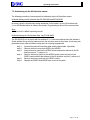
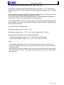
1
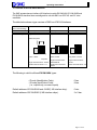
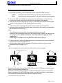
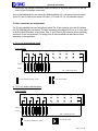
Actuator/Sensor Interface Units (AS-Interface)
Operating Instructions
Operating Instructions
____________________________________________________________________________
Actuator/Sensor Interface Units (AS-Interface)
____________________________________________________________________________
EX12#-SAS2
EX12#-SAS4
EX12#-SAS5
(# = 0, 1, 2)
____________________________________________________________________________
____________________________________________________________________________
____________________________________________________________________________
____________________________________________________________________________
Page: 1 of 22
Actuator/Sensor Interface Units (AS-Interface)
Operating Instructions
CONTENTS
Page:
1. GENERAL INFORMATION ABOUT THE AS-INTERFACE.......................................... 4
2. OVERVIEW OF EX12#-SAS# DEVICES.......................................................................... 8
4. INSTALLATION OF THE EX12#-SAS# SLAVES.........................................................11
5. VALVE CONNECTOR PIN ASSIGNMENT....................................................................12
6. TECHNICAL SPECIFICATION OF THE EX12#-SAS#................................................13
7. SLAVE ADDRESS SETTING PROCEDURE................................................................15
7.1. A DDRESSING VIA THE HANDHELD PROGRAMMING DEVICE ............................................16
7.2. A DDRESSING VIA THE AS-INTERFACE MASTER..............................................................17
8. DIAGNOSTIC AND SAFETY FUNCTIONS .................................................................18
8.1 ERROR LED: RED LAMP "ERR" ....................................................................................18
8.2 CLEAR/HOLD S WITCH ...................................................................................................18
8.3 LEDS FOR POWER SUPPLY : GREEN LEDS "PWR" AND "EXT" ...................................19
9. FURTHER INFORMATION ...............................................................................................20
10. SMC CONTACT ADDRESSES .....................................................................................21
NOTES ......................................................................................................................................22
Page: 2 of 22
Actuator/Sensor Interface Units (AS-Interface)
Operating Instructions
Safety recommendations
-
Please read the operating manual carefully before starting up the SI unit; retain the
operating manual at hand for later reference. Please observe all safety precautions
given in the manual, as well as the following safety recommendations:
!
Attention!
In order to avoid damage to the SI unit ( which could possibly result
in system faults), the SI unit must not be installed in the following
areas:
- areas where the SI unit can come into contact with water
- areas where the temperature of the SI unit would exceed 50°C
- EX areas
!
Attention !
Switch off both the compressed air and the supply voltage before
installation of and maintenance on the SI valve manifold.
-
Only qualified control and automation technicians are permitted to install and maintain
the equipment.
-
Pay attention to the technical data when installing the SI unit and the valves.
-
The mains supply circuit for the valves must conform to the PELV (Protection
Extra Low Voltage) requirements in IEC 364 -4 -41. Allowable valve voltage
range is +21.6v to + 26.4v DC.
-
Use only certified AS-Interface mains supply circuits for the voltage supply to the ASInterface.
-
Do not open and try to repair the equipment yourself, nor attempt to modify it.
SMC are not liable for any damage resulting from such activities.
Page: 3 of 22
Actuator/Sensor Interface Units (AS-Interface)
Operating Instructions
1. General information about the AS-Interface
The AS-Interface system replaces the expensive parallel wiring of single distributed sensors
(inputs) and actuators (outputs). ”Distributed” here means decentralized, local inputs and
outputs (I/Os) using only a few bits (1-4 bits).
Most inputs and outputs (I/Os) are binary or discrete and are located beneath the well-known
fieldbus level, according to the OSI/ISO reference model. Here ”binary”, ”discrete” or digital
means simple ON/OFF operations, such as, for example, the 24 V DC ON/OFF control of the
SMC solenoid valves without transmission of analog values via the ASI network.
Compared with other fieldbuses, the AS-Interface is both relatively easy to use and cost effectivel. The system does not require termination resistors or baud rate setting.
The data and energy transmission is done via a simple 2-wire cable (Yellow AS-Interface
standard cable) via a connector and an APM (Alternating Pulse Modulation) modulation using
sin²() pulses, which have fewer harmonics and low EMC (Electromagnetic Compatibility)
emission. The standard AS-Interface cable enables simple and quick installation by using an
insulation piercing connection.
For the data decoupling of the yellow cable, a special AS-Interface power supply device must be
used. This AS-Interface power supply is directly connected to the yellow cable (ASI+ve and ASIve line) and is positioned as near as possible to the master in order to minimize the voltage drop.
In addition to the yellow cable mentioned above, some AS-Interface units are provided with
similar (optional) black cables for additional actuator power supply.
Only power supply devices conforming to the PELV (Protection Extra Low Voltage) standard
should be connected to the black cable(s). Ordinary +24V DC transformers must under no
circumstances be used.
The SMC interface units which are provided with an additional +24V DC power supply for
electrical components (black cable connection) can be used for emergency OFF applications.
The yellow and black cables are completely independent of one another, i.e., when the +24V DC
supply (black cable) is switched off, the AS-Interface circuit (yellow cable) remains in operation.
Because of their special geometrical asymmetry and size, both the yellow standard cable and
the optional black AS-Interface cable are mechanically protected against incorrect polarity.
The AS-Interface is a single master/multiple slave system, i.e., there is only one master
controlling several slaves in an AS-Interface net. A maximum of 31 slaves can be connected to
one master within an AS-Interface net. Both the master and the slaves are connected via the
yellow AS-Interface standard cable.
The maximum length of the yellow cable, without a repeater, is 100 m, which includes the stub
lines and all branch lines of the AS-Interface net free topology.
The maximum length of the black cable depends on the power consumption of the actuators,
and is normally shorter than the yellow cable. The voltage directly at the actuators must be
confirmed to be within the allowable voltage range.
The AS-Interface master sends as many telegrams as there are connected and active ASInterface slaves in the net. Each slave is sequentially and cyclicly accessed by these telegrams,
Page: 4 of 22
Actuator/Sensor Interface Units (AS-Interface)
Operating Instructions
starting with the slave with the lowest active address.
For the master there are as many slave addresses as there are AS-Interface chips connected
and activated in the net.
The time required to access all active slaves is the data cycle time (approx. 5 ms for a
maximum of 31 slaves). The access time of all active slaves is fixed or determined (real-time
ability) and is proportional to the number of activated slaves. If the number of activated slaves is
halved, the access time is also halved:
5 ms * 15/31 = approx. 2.4 ms.
The physical system is controlled by the system controller (SPS, PC or controller), and not by
the master.
The master, however, notices after at most 5 ms (max. cycle time) if a slave trips out.
The AS-Interface telegram conveys the message between the master and the slaves in both
directions. First the master output data is sent to the slaves (write), then the slave input data, per
slave and within one telegram, is returned to the master (read).
The AS-Interface telegram consists of the master call, the master idle time (master pause), the
slave response and the slave pause (see below).
AS-interface-telegram
(From master to slave,and from slave to master, for a single slave access):
master-call
ST CB A4 A3 A2 A1 A0 I4 I3 I2 I1 l0 PB EB
ST
EB
I4-I0
A4-A0
CB
master pause
3-1O BT
slave response
ST I3 I2 I1 I0 PB EB 1 BT
start bit is always 0
BT
end bit is always 1
PB
5 bit from master to slave
I3-I4
5 bit for slave-address
(00000-1 1 1 1 1 binary corresponds to 0-31 decimal)
control bit : = 0 for data/parameter/address access
= 1 for command access
slave pause
1 bit-time = ca. 61µs
parity bit (even parity)
bit from slave to master
For a description of the master, refer to the master manufacturer´s handbook, where details of
the particular AS-Interface master used can be found. The master answers this telgram
cyclically for all connected and activated slave addresses.
The main component of the AS-Interface is a special slave chip, which can control:
a) 4 inputs only
b) 4 outputs only
c) 4 inputs + 4 outputs simultaneously, i.e., within one telegram.
In case c), a system having 31 slaves will have a maximum of 248 binary inputs and outputs.
This chip is provided with 4 parameter bits for non-cyclic setting of special slaves. If these
parameter bits are used, the master sends asynchronous parameter telegrams between normal
data cycles.
Note:
- EX12#-SAS#-units do not use the parameter bits of the internal AS-Interface chips.
Page: 5 of 22
Actuator/Sensor Interface Units (AS-Interface)
Operating Instructions
The SMC AS-Interface slaves are provided with an internal watchdog timer (WDT). This WDT
provides a safety fall-back function, i.e., in the event of a communication error the outputs will be
reset to a definite state (normally all OFF) and the red ERR LED will light up.
The slave address, which is non-volatilely stored, can be changed automatically via the master
or manually via a handheld programming device (HP). The handheld programming device
replaces the actual AS-Interface master during address programming. It is not absolutely
necessary to use the handheld programming device to set the addresses, as each slave can be
directly programmed by the master.
Many slave addresses cannot be set simultaneously; one telegram can only be addressed to a
single slave (5 bits are required for one slave address: A4-A0 implies 25 = 32 slaves).
The address 0 is usually reserved for a new AS-Interface slave which has not previously been
connected to the AS-Interface net. The slave address 0 can only be used once within the net.
The address 0 is used for automatically setting the address via a master telegram. In this case,
the master allocates the new slave the lowest, unused address between 1 and 31.
Note:
-
The AS-Interface master only permits one address 0. Each EX 12 #-SAS2 device contains
two ASI slaves, as well as two addresses, both of which are preset to 0. For this reason, use
of the blind connector supplied by SMC is essential when first starting up the system via the
master (see 7.2).
Page: 6 of 22
Actuator/Sensor Interface Units (AS-Interface)
Operating Instructions
Overview of common AS-Interface features:
Topology
Medium for data + energy
Length of bus cable
Number of slaves
Number of participants
Adresses
Messages
Bit rate
Cycle time
Error detection
Device interface
Process data in the Master
Master functions
Free structure, i.e., line, free, star, stub lines, etc.
- Unshielded 2-wire AS-Interface cable,
(= yellow AS-Interface standard cable)
- Insultion piercing connections according to IEC 60352-6
Max. 100 m (without repeater)
Max. 31
Up to 4 sensors and 4 actuators per slave
(max. 124, bidirectional, max. 248 binary participants)
Each slave is allocated a definite address.
Address setting by means of the master or a programming
tool (e.g., a handheld programming device and cable jack)
Message from master to each slave address, with
immediate response from slave (bidirectional)
4 bits (pure data) per slave and message
Max. 5 ms, for 31 (max.) connected slaves
Incorrect messages are reliably identified and repeated
4 configurable data interfaces (as inputs or outputs or
bidirectional) plus 4 parameter outputs and 2 control outputs
(Strobe)
Cyclic polling of all participants; cyclic transmission of data
to the host or to the slaves
Initialization of the network, identification of participants,
acyclic setting of the slave parameter valves, diagnosis of the
net and AS-Interface slaves, error messages to the host,
setting of addresses in replaced slaves
Notes:
-
In addition to its slave address, every certified slave has a fixed and non-volatile ID- and I/0
code (Identification - and Input/Output Code) according to the AS-Interface Association, for
slave identification by the master.
-
The ID-, I/0 code and the address are non-volatilely stored in an internal EEPROM after
power OFF. Only the slave address can be changed by the user (via the master or a
handheld device).
-
EX12#-SAS# devices are not provided with sensor inputs.
Page: 7 of 22
Actuator/Sensor Interface Units (AS-Interface)
Operating Instructions
2. Overview of EX12#-SAS# devices
The SMC actuator/sensor interface (AS-Interface) models EX12#-SAS4, EX12#-SAS2 and
EX12#-SAS5 described here are designed for use with SMC non-IP65 VQ- and SY valve
manifolds.
The table below shows a type overview of SMC non-IP65 AS-Interfaces:
Model-no.:
(#=0,1,2 for housing)
AS-interface cable
Solenoid outputs
Schematic diagrams
EX12#-SAS4
EX12#-SAS2
yellow + black
4
Fig. 1a:
EX12#-SAS5
yellow + black
8
Fig. 1b:
yellow
4
Fig. 1c:
yellow + black
only yellow, no black
single solenoid valves :
1/2/3/4/5/6/7/8
double solenoid valves :
1/2/3/4
single solenoid valves:
1/2/3/4
double solenoid valves: 1/2
attachment plate
valves
yellow + black
end plate
single solenoid valves: 1/2/3/4
double solenoid valves : 1/2
The following is valid for all three EX12#-SAS# types:
- ID-code (Identification Code):
- I/O-code (Input/Outout Code):
(i.e., outputs only, no sensor inputs)
Default address of EX12#-SAS4 and –SAS5(1 AS-Interface chip):
Default address of EX12#-SAS2 (2 AS-Interface chips):
0 hex.
8 hex.
0 dec.
2 x 0 dec.
Page: 8 of 22
Actuator/Sensor Interface Units (AS-Interface)
Operating Instructions
Notes:
-
If sensor inputs are required, use a generic AS-Interface I/0 module.
-
All EX12#-SAS#-models are provided with ADDR sockets for connection to the handheld
programming device for the setting of addresses using a special (1.3 mm) jack.
Overview of models numbers :
SMC
Model number
EX120-SAS4
EX121-SAS4
EX122-SAS4
EX120-SAS2
EX121-SAS2
EX122-SAS2
EX120-SAS5
EX121-SAS5
EX122-SAS5
Max. no. of
single/double
solenoids
4/2
No. of AS-Interface
chips or slave
addresses
1
Additional +24 V DC
Solenoid power
supply (black cable)
yes
8/4
2
yes
4/2
1
no
Overview of the EX 12 frame (housing):
Three different frames (housings) of type EX12# are available, each suitable for one SAS type
(i.e., there are 3 x 3 = 9 different EX12# SMC AS-Interface devices, listed above):
EX120:
EX121:
EX122:
0 for direct mounting, without DIN rail
1 for mounting on DIN rail, with ribbon cable
2 for mounting on DIN rail, without ribbon cable
(VQ valve series)
(SY series)
(SY series)
Page: 9 of 22
Actuator/Sensor Interface Units (AS-Interface)
Operating Instructions
3.Components on the cover plate
(simplified overview - not to scale)
Component
Green PWR LED
Type
All types
Red ERR LED
All types
Description
Green LED for AS-Interface power supply (yellow
cable)
Red LED for communication error (watch dog)
green EXT LED
(24VDC PELV)
EX12#-SAS4 and –SAS2
Green LED for valve solenoid power supply
ADDR1-, ADDR2jack sockets
one socket : EX12#-SAS4,
-SAS5
two sockets: EX12#-SAS2
CLEAR/HOLD switch
All types
Jack sockets for handheld programming device for
address setting (2 slave addresses, as there are 2
ASI chips)
ADDR1: for chip no. 1 or solenoid outputs
0, 1, 2 and 3
ADDR2: for chip no.2 or solenoid outputs
4, 5, 6 and 7
!! Solenoid output no. 0 is assigned to the first
socket after the device !!
Mode switch:CLEAR/HOLD
CLEAR: in the event of a communication error, all
valves are switched to the OFF position
HOLD: in the event of a communication error, all
valves remain in their current ON/OFF positions .
AS-Interface connector
for the yellow cable (left)
Connector for the black
cable (right)
All types
Ribbon cable connector for the AS-Interface
EX12#-SAS4 and –SAS2
External +24VDC power supply for the valve
actuators.
Page: 10 of 22
Actuator/Sensor Interface Units (AS-Interface)
Operating Instructions
4. Installation of the EX12#-SAS# slaves
We recommend the following installation procedure:
1. Ensure that the position of the CLEAR/HOLD switch on the cover plate is correct:
CLEAR:
HOLD:
In the event of a communication error, all valves are switched OFF.
In the event of a communication error, all valves retain their current setting.
2. Connect the SMC valve manifold connecting plate to the AS-Interface unit via the 18 pin
connector on the side, and lock the connector using the stopper clip at the rear.
2*. Place the ASI unit on the DIN rails and connect it to the SMC valve manifold mounting plate
using the 18 pin connector. Finally, tighten the securing screws.
Note:
- If the unit has been supplied pre-asssembled to the manifold, ignore steps 2 & 3
3. Clamp the yellow and black AS-Interface cable (if provided) in the recess in the underside of
the AS-Interface connector (Fig. 1).
Notes:
-
The AS-Interface connector cover can only be mounted one way round!
Because of the asymmetrical shape of the AS-Interface cable (profiled), the cable can only
be inserted in one way. Make sure that the connecting cable seats properly in the
socket (Fig. 1).
Before doing any installation work, check that the cables are long enough.
5. Press the front cover of the AS-Interface connector downwards into the socket until the first
mechanical locking stop engages (Fig. 2).
6. Carefully tighten both screws (2 screws per AS-Interface connector) until the second
mechanical locking engages (Fig. 3).
Note :
- Do not over-tighten the metal screws: the plastic thread could be damaged.
srews
AS interface connector cover
plug contact
AS interface
cable
Fig. 1
Fig. 2
Fig. 3
Applicable to the yellow cable: the green PWR LED and the EXT LED light up when the power
supply to the AS-Interface is switched on.
Applicable to the black cable (if provided): only the EXT LED lights up when the valve power
supply is switched on. The ERR LED does not light up, as this would imply a communication
error between the AS-Interface master and the AS-Interface slave(s).
* only, if EX12# housing is mounted on DIN rail
Page: 11 of 22
Actuator/Sensor Interface Units (AS-Interface)
Operating Instructions
7. Identify both AS-Interface connectors (yellow and black) on the white labels found on the top
covers of the AS-Interface connectors.
Set only free addresses for new slaves (the default address is 0) and transmit the information
via the ID- and I/O code to the master: ID code = 0, I/O code = 8 (i.e.,only solenoid outputs).
5. Valve connector pin assignment
The SI valve manifold has been internally pre-wired.The 18 pin connector joins the AS-Interface
unit EX12#-SAS# to the valve block. The pins have been pre-assigned for the 4 (or 8, in the case
of the EX12#-SAS2 model) output drives. Pins 17 and 18 are for the common ground (earthing),
and pins 9-16 are not connected. The wiring of the SI valve manifold can take various forms,
depending on the application.
a) For 4 or.8 single solenoid valves
18 pin connector
1
3
5
7
9
11
13
15
17
2
4
6
8
10
12
14
16
18
Valve 0
2
Valve
4
6
3
1
5
7
0V ( common ground )
? For EX12#-SAS4 and –SAS5
+
? For EX12#-SAS2
b) For 2 or 4 double solenoid valves
18 pin connector
1
3
5
7
9
11
13
15
17
2
4
6
8
10
12
14
16
18
Valve 0
0
1
1
2
Solenoid
b
a
b
a
a
2
b
3
3
a
b
0V ( common ground )
? For EX12#-SAS4 and –SAS5
+
? For EX12#-SAS2
Page: 12 of 22
Actuator/Sensor Interface Units (AS-Interface)
Operating Instructions
6. Technical specification of the EX12#-SAS#
Serial interface protocol
According to AS International Association
Specification,
"Complete Specification, Version 2.0 ".
Slave protocol chip
ISA3+ compatible AS-Interface slave chip:
AS2701
AS-Interface power supply voltage
26.5 V DC to 30.5 V DC at the AS-Interface
slave via yellow AS-Interface standard cable:
2 x 1.5 mm²
Valve solenoid power supply voltage
(except for EX12#-SAS3)
+24 V DC ± 10% (21.6 V DC to 26.4 V DC),
via optional black AS-Interface cable:
2 x 1.5 mm².
Note:
Use only power supply units conforming to
PELV standard (IEC364-4-41).
Load current per valve solenoid
- max. 100 mA, 2.1 W rated power,
except for EX12#-SAS3 (no black cable)
max. 70 mA, 1.5 W for EX12#-SAS3
Valve solenoid driver circuit
p-channel MOS-FET transistor driver
(common ground (earth))
Reverse (incorrect)
connection protection
Provided by a series-wired diode on the positive
side of the AS-Interface power supply.
Surge (over-voltage) protection
Provided via a Zener suppressor diode between
the AS-Interface positive and negative voltage
supply terminals.
ID-Code
0 hex
I/0-Code
8 hex (i.e., only outputs, no sensor inputs)
Default addresses
0 dec. for EX12#-SAS4 and EX12#-SAS5
2 x 0 dec. for EX12#-SAS2 (2 slaves)
Parameter bits of AS-Interface
slave protocol chip
Not connected, not used
Safety fall-back function
a) Switch position CLEAR (Default):
all valves are switched OFF in the event of
a communication error.
b) Switch position HOLD:
all valves retain their last valid ON/OFF position
as per last valid communication telegram.
LED indicators
a) PWR (green) for AS-Interface voltage
Page: 13 of 22
Actuator/Sensor Interface Units (AS-Interface)
Operating Instructions
supply, typically 30 V DC
b) EXT (green) for valve solenoid voltage
supply, 24 V DC nominal.
c) ERR (red) for communication error.
Watchdog timer
One provided per interface chip, having a
delay time of ca. 50 ms.
In the event of a communication error,
the red ERR LED lights up. After error correction,
the ERR LED automatically goes out.
Opto-coupler
Provided between AS-Interface and valve
solenoid driver.
Connectors
a) Yellow and black AS-Interface cable
b) Sockets for handheld programming device
used to set addresses.
Two jacks for EX12#SAS2 (ADDR1/2).
One jack for EX12#-SAS4 and –SAS5 (ADDR).
Note:
A special dummy jack (1.3 mm) is necessary
for programming the EX12#-SAS2 via the AS
interface master.
Insulation piercing connection
of yellow and black AS
interface cables.
According to IEC 60352-6
EMC test standards
Emission according to EN50081-1.
Interference according to EN50082-2.
Protection class
IP20
Operating temperature
0 ~ 50ºC
AS international Association
test certificate
Provided by the AS-Interface test laboratory
in Leipzig, Germany.
Applicable SMC-series valves
VQ1000/2000 (Negative common polarity)
SY 3000/5000 (Negative common polarity)
Single solenoid valves
max. 4 for EX12#-SAS4and –SAS5
max. 8 for EX12#-SAS2
For future information on SMC valves and valve connection terminal boards, refer to SMC valve
catalogues.
Page: 14 of 22
Actuator/Sensor Interface Units (AS-Interface)
Operating Instructions
7. Slave address setting procedure
There are two methods of setting the slave addresses:
1. Using the AS-Interface master.
2. Using the handheld programming device.
When using automatic programming via the master (address 0), the mechanical dummy jack
must be used to disconnect one of the two AS-Interface chips of the EX12#SAS2 from the yellow
AS-Interface cable.
No dummy jack is required for the EX12#SAS4 and –SAS5 versions.
For #= 0, 1, 2
Model number:
Address programmed via ASInterface master (bus)
EX12# - SAS4
EX12# - SAS2
yes
yes
Address programmed via
hand programming device
and dummy jack
yes
yes
(using dummy jack)
EX12# - SAS5
yes
yes
1,3 mm
The mechanical dummy jack
Address range: 0 - 31 decimal. Do not use the address 0 for normal slave addressing. The
address 0 is reserved for automatic addressing via the master.
Page: 15 of 22
Actuator/Sensor Interface Units (AS-Interface)
Operating Instructions
7.1. Address setting via the handheld programming device
A special dummy jack is required for the ADDR1/2-sockets on the front cover plate when
addressing via the hand programming device (HP).
When programming using the HP, the ”true” AS-Interface master is dicsonnected from the slave
being addressed, and the HP device assumes the role of master. During this procedure, all other
slaves in the circuit remain connected to the ”true” master.
After successful completion of addressing via the HP, the ERR LED will go off.
a)
Models having one AS interface chip: EX12#-SAS4 and EX1 2#-SAS5
Step 1: Remove the dust cover (ADDR).
Step 2: Plug the cable jack of the HP into the ADDR socket.
Step 3: Set and transmit the slave address into the AS-Interface circuit using the HP.
Step 4: Remove the cable jack from the ADDR socket.
Step 5: Replace the ADDR dust cover.
b)
Models having two AS-Interface chips: only EX12#-SAS2
Step 1: Remove the dust covers of ADDR 1 and 2.
Step 2: Plug the cable jack of the HP carefully into the ADDR1 socket.
Step 3: Perform the slave address setting of slave chip no. 1 using the HP (range:1 to
31 decimal).
Select slave addresses not already used in the AS-Interface circuit.
Step 4: Remove the cable jack from the ADDR1 socket.
Step 5: Plug the cable jack of the HP carefully into the ADDR2 socket.
Step 6: Perform the slave address setting of slave chip no. 2 using the HP. Use a
different address to that used in step 3 (range 1 to 31 decimal).
Step 7: Remove the cable jack from the ADDR2 socket.
Step 8: Replace the ADDR1 and ADDR2 dust covers on the cover plate.
Page: 16 of 22
Actuator/Sensor Interface Units (AS-Interface)
Operating Instructions
7.2. Addressing via the AS-Interface master
The following procedure is recommendet for addressing via the AS-Interface master.
a) Models having one AS-Interface chip: EX12#-SAS4 and EX12#-SAS5
No dummy jack is required when setting addresses via the master, as only AS-Interface chip
(= one AS-Interface slave) is visible to the master. Programming is done in the normal manner.
Note:
-Refer to the AS-I Master operating manual.
b) Models having two AS-Interface chips: only EX12#-SAS2
The EX12#-SAS2 unit is pre-set with the address 0, i.e., both internal slaves have the address 0.
As the address 0 may only be present once in the circuit as seen by the master, the dummy jack
provided must be used to isolate the chip which is not being programmed.
step 1:
step 2:
step 3:
step 4:
step 5:
Step 6:
Connect the yellow AS-Interface cable (and the black cable, if provided).
Remove the dust covers from ADDR1 and ADDR2.
Insert the dummy jack into the ADDR2 socket and set the address of the ASInterface chip no. 1 (=slave no.1).
Remove the dummy jack from the ADDR2 socket, insert the jack into the
ADDR1 socket and set the address of the AS-Interface chip no.2 (=slave no.2).
Remove the dummy jack from the ADDR1 socket.
Replace the ADDR1 and ADDR2 dust covers on the plate.
Page: 17 of 22
Actuator/Sensor Interface Units (AS-Interface)
Operating Instructions
8.
Diagnostic and safety functions
8.1 ERROR LED: red lamp "ERR"
The red ERR LED (error LED) indicates a communication error between the master and a
slave. A communication error arises when the master, despite repeated calls, fails to receive a
correct answer from the slave. When a communication error arises, the master reports a
configuration error and removes the failed slave from the circuit in order to ensure that the
remaining slaves in the circuit can continue functioning. The master is not able to determine
whether the error arises from the slave itself or from a line disturbance. Because of their internal
watchdogs, SMC slaves EX12#SAS# can recognize that no telegrams are being sent, and
announce a communication error via the ERR LED. In this case, it is up to the user to decide
whether the valve actuator should be reset to a preset state or should be left in the last operating
position (see Section 8.2).
On error correction, the red ERR LED automatically goes off and the slave is brought back into
operation. It is not necessary to switch off the circuit and restart it again.
8.2 CLEAR/HOLD Switch
The CLEAR/HOLD switch is a two-position switch on the cover plate; its purpose is to provide a
safety fall-back function.
If the communication between the master and the slave is interrupted, the slave internal
watchdog timer indicates an error (red ERR LED lights up). In the event of such an error, the
open/shut status of the valves is pre-determined by the CLEAR/HOLD switch setting on the
cover plate:
1. CLEAR:
2. HOLD:
In the event of a communication error, all valves are switched off
(valves OFF and ERR LED = ON).
There are 2 modes when ERR LED = ON:
a) “real ”communication error:
all valves retain their
previous, valid ON/OFF status
b) when using the HP device
not a communication error
Note:
The CLEAR/HOLD switch is only active when the red ERR LED lights up.
If the HOLD position is selected, the valves initially go to the OFF position when the AS-Interface
power supply is first switched on. The WDTs are reset after power ON and set if no master call
is made to the slave within a period of ca. 50 ms. On resetting the AS-Interface master, access
to the slave is again opened.
After eliminating the cause of the communication error (red ERR LED goes off), the master
regains control of the solenoid outputs. Depending on the master used, during the first start-up of
the slaves it is possible that the red ERR LEDs go on for a few seconds; they will go off again
after successful activation.
Page: 18 of 22
Actuator/Sensor Interface Units (AS-Interface)
Operating Instructions
8.3 LEDs for power supply: green LEDs "PWR" and "EXT"
PWR (power) monitors the AS-Interface voltage power supply (26.5 V – 31.6 V at the slave,
yellow cable) and EXT (external) the additional valve solenoid power supply (+24V ± 10%,black
cable).
EXT is completely independent of PWR. If the black cable provided is not connected, the valve
solenoids will have no power supply (EX12#SAS4 and -SAS2).
In the case of model EX12#SAS5 (without black cable), the valve solenoids are supplied with
power from an internal +24V voltage regulator via the yellow cable.
If the voltage falls below a certain value, the two green LEDs will not switch off completely, but
will glow weakly. If this occurs, ensure that the following voltages are present, especially at the
slaves and the black cable:
a) yellow AS-Interface standard cable:
AS-Interface voltage at ASI unit : 29.5 ~ 31.6 V
AS-Interface voltage at slave :
26.5 ~ 31.6 V (max. voltage drop of 3 V/100 m)
b) optional black AS-Interface cable ( not with EX12#SAS5):
valve solenoid voltage at the device: 23.6 ~ 28.5 V DC (26 V DC nominal)
valve solenoid voltage at the slave: 21.6 ~ 26.4 V DC ( +24 V DC ± 10%)
Notes:
- Avoid voltages greater than +26.4 V DC for the solenoid power supply. Use the correct
connector for additional solenoid power supply (black). Do not use 30 V supply for the black
AS-Interface cable.
- Note that the valve solenoid voltage in the circuit must be a bit higher than the target voltage
(24 V DC) directly at the valve. The voltage drop depends only on the current consumption in
the black cable.
Page: 19 of 22
Actuator/Sensor Interface Units (AS-Interface)
Operating Instructions
9. Further information
a) ID code = 0hex, I/O code = 8hex is valid for all three EX12#SAS# types.
Note that for model EX12#SAS2 the master has to be given the ID- and I/O codes twice, as
there are two slaves.
b) Yellow and black AS-Interface cable (AS-Interface- and valve solenoid voltage supply):
The AS-Interface unit can be disconnected from the yellow and black AS-Interface cables
when the power supply (yellow and black) is switched ON. This also applies to the
EX12#SAS5 (without black cable). The remaining AS-Interface circuit is not adversely
affected by this.
c) For models supplied with black AS-Interface cable (for additional valve solenoid power
supply). Disconnection of the valve manifold board should only be done once the solenoid
power supply is switched OFF.
Caution:
- Use only voltage supply units which conform to PELV standard (IEC 364-4-41) for
+24V DC solenoid power supply (this does not apply to model EX12#SAS5).
d) Set the position of the CLEAR/HOLD switch and both addresses before installation of the ASInterface cable.
e) Ensure that the total length of the yellow AS-Interface cable does not exceed 100m per ASInterface power supply unit.
f) Ensure that +24 V DC ± 10% is available at the slave for valve solenoid power supply. (This
could possibly require a higher voltage at the power supply unit, as the voltage drop is directly
proportional to the length of the yellow AS-Interface cable.).
g) After switching on the AS-Interface power supply, the green PWR LED should light up. The
red ERR LED might light up for a few seconds, depending on the actual master used. Once
the master has recognized all the slaves, the red ERR LED will go out.
h) If, when switching on the power supply, the mode switch is in the HOLD position, all valves
will initially go to the OFF position (no current flow).
i)
j)
Both AS-Interface cables (yellow and black) are protected against both incorrect polarity and
incorrect insertion.
If the cables are incorrectly connected, no damage to the SMC AS-Interface unit will occur, as
the impedance and phase values will be out of range.
In the worst case (e.g., max. cable length of 100 m and 31 AS-Interface slaves),
communication between the other participants will (only) be disturbed by reversing the black
and yellow cables.
It is recommended that new slaves be installed and address-programmed one after the
other, and that the ID code and I/O code of each new slave be checked against the master
configuration.
k) As the AS-Interface is an open system, accessories available on the open market can be
installed. Refer to the certified devices in the CD ROM product catalog of your national ASInterface manufacturers association.
Most available AS-Interface accessories simplify usage, and are easy to install.
Page: 20 of 22
Actuator/Sensor Interface Units (AS-Interface)
Operating Instructions
l)
Note that some passive housings of common AS-Interface I/O modules are designed for
yellow and black AS-Interface cables, while others are designed for 2 x yellow cables (for
branching).
10. SMC contact addresses
SMC (UK)
Belfast RC
Bristol RC
Coleshill RC
SMC Pneumatics (UK) Ltd
Unit 3, Shaftesbury House
Edgewater Road
Belfast
BT3 9JQ
Tel: 01232 778414
Fax:: 01232 778422
SMC Pneumatics (UK) Ltd
Unit 5 East Gate Office Centre
Eastgate Road
Eastville
Bristol
BS5 6XX
Tel: 01179 522155
Fax: 01179 522186
SMC Pneumatics (UK) Ltd
24, The Courtyard
Gorsey Lane
Coleshill
Warwicks
B46 1JA
Tel: 01675 467177
Fax: 01675 465073
Crawley RC
Cumbernauld RC
Droitwich RC
SMC Pneumatics (UK) Ltd
9, Pelham Court
Pelham Place
Broadfield , Crawley
W.Sussex RH11 9AZ
Tel: 01293 614094
Fax: 01293 614135
SMC Pneumatics(UK) Ltd
1, Carradale Crescent
Broadwood Bus. Park
Cumbernauld
Glasgow G68 9LE
Tel: 01236 781133
Fax: 01236 780611
SMC Pneumatics (UK) Ltd
Unit 3, Wassage Way
Hampton Lovett Ind. Estate
Droitwich
Worcs. WR9 0NX
Tel: 01905 774544
Fax: 01905 797343
Gateshead RC
Ipswich RC
Manchester RC
SMC Pneumatics(UK) Ltd
Unit B6, Marquis Court
Marquis Way
Team Valley Trading Est.
Gateshead
Tyne & Wear
NE11 0RU
Tel: 0191 4872040
Fax: 0191 4872041
SMC Pneumatics(UK) Ltd
Unit 6&7 Alpha Bus. Park
Whitehouse Road
Ipswich, Suffolk
IP1 5LT
Tel: 01473 240040
Fax: 01473 747707
SMC Pneumatics(UK) Ltd
3, Modwen Road
Waters Edge Business Park
Ordsall Lane Salford
Manchester
M5 3EZ
Tel: 0161 8767371
Fax: 0161 8767372
Milton Keynes RC
Poole Regional Centre
Sheffield RC
MK Regional Centre
SMC Pneumatics(UK) Ltd
Vincent Avenue
Crownhill
Milton Keynes
Bucks
MK8 0AN
Tel: 01908 265247
Fax: 01908 262705
SMC Pneumatics(UK) Ltd
Unit 4, Acorn Bus Centre
Ling Road
Poole
Dorset
BH12 4NZ
Tel: 01202 732233
Fax: 01202 737743
SMC Pneumatics(UK) Ltd
Unit 4,
North Anston Bus. Centre
Houghton Road
North Anston
Sheffield
S31 7JJ
Tel: 01909 565504
Fax: 01909 569717
SMC Eire
SMC Pneumatics (Irl) Ltd
2002 Citywest Business
Campus, Naas Road
Saggart
Dublin
Tel: +353 1 4501822
Fax: +353 1 4502710
Page: 21 of 22
Actuator/Sensor Interface Units (AS-Interface)
Operating Instructions
NOTES
Page: 22 of 22