1
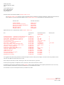
Maintenance Manual for
Evenheat Kiln Model
GTS 2541
RampMaster II, 400V, 15.7A
This Maintenance Manual provides information needed to properly maintain, inspect and repair Evenheat Kiln model GTS 2541, 400V, 15.7A.
All maintenance and inspection procedures shall be performed with all kiln breakers or fused disconnects in the OFF and locked position unless
specifically noted in the procedures.
All maintenance, inspection and repair procedures must be performed while the kilns firing chamber is at ambient room temperature
unless otherwise stated.
All maintenance and repair operations listed in this manual require the service of licensed personnel only unless otherwise stated.
Routine Maintenance and Inspection
Lid Band Tightening
The kiln lid uses a stainless steel “lid band” as the mounting area for the lid hinge, lid handles and lid chains. During firing this lid
band will expand and contract. As a result it may become slightly loose. Screw clamps are provided on the lid band for the tightening
purposes.
Using a large, standard screwdriver rotate all lid band screw clamp screws in a clockwise position until tight. While these
screws must be tight - do not over tighten, stripping of the screw can result.
This procedure should be performed after each of the first 4 firings. Subsequent inspection of lid band tightness should be
performed every tenth firing.
This procedure can be performed by the user or by personnel designated by the user.
Lid Interrupt Switch Inspection
The lid interrupt switch enables the safety relay circuitry. This devise should be checked for proper operation after each or the first 4
firing and after every tenth firing. The purpose of these tests is to verify that the safety relay(s) are working properly.
Testing the operation of the circuitry
Steps 1 through 7 can be performed by the user or by personnel designated by the user.
Step 8 requires licensed electrical personnel.
1.
2.
3.
4.
5.
6.
7.
Close the kiln lid and switch all kiln breakers or fused disconnects to the ON position.
Throw the controllers power switch to the ON (I) position.
Program the control to fire up to 100°C (212°F) and start the firing.
Allow the kiln to increase in temperature up to 55°C (130°F).
Open the lid fully. Some heat will escape – please use caution.
The temperature should begin to fall and the heating elements will remain dark (they should not begin to glow red).
Leave the lid open for 10 minutes. The heating elements should remain dark during this time. If this is true, the kiln has
passed the Lid Interrupt Switch test and is operating correctly.
8. If the heating elements begin to heat (glow red) during this test, with the lid open, service to the safety circuitry is
necessary. Service must be performed by licensed electrical personnel. Do not operate the kiln until the lid interrupt
circuit has been repaired.
Firebrick Inspection
Your kiln firing chamber is made of a material referred to as “firebrick”. While this material is very strong, Inspection and
Maintenance is needed.
When fired, the kiln floor, lid and side walls may show signs of cracking. Small, hairline cracks are absolutely normal and will not affect
the operation or performance of the kiln.
During firing small pieces of the firebrick may become dislodged. In this event, apply repair cement (available from your dealer) to the
dislodged brick and carefully put it back in place. Avoid getting repair cement on the heating elements. Before attempting this type of
repair switch all breakers or fused disconnects to the OFF and locked position. This procedure can be performed by the user.
Page 1 of 5
Evenheat Document #CEMT 14-05
June 13, 2006
When firing, ware may fall over and make contact with the firebrick. When doing so it may leave deposits on the firebrick. These
deposits must be removed before further firing. Use a small tool such as a screwdriver to remove these deposits from the firebrick. Use
care so as not to destroy the firebrick. Before attempting this type of repair switch all breakers or fused disconnects to the OFF and
locked position. This procedure can be performed by the user.
Supply Cable Inspection
The supply cable is responsible for delivering the required power to the kiln. This cable must be inspected before every firing for signs of
damage. Before inspecting switch all kiln breakers or fused disconnects to the OFF and locked position. Particular attention must be paid
to damage caused by contact with the hot surfaces of the outer jacket. If the cable shows any sign of melting or deformation it must be
replaced immediately. Other possible damage may include splices or openings in the coating of the cable. Any signs of damage would
indicate that a possibly hazardous condition exists and immediate replacement is necessary. If damage does exist, do not switch the
breakers or fused disconnects to the ON position until repairs have been made. Daily inspection of the cable can be performed by the
user or personnel designated by the user. Replacement of damaged supply cable is to be performed only by licensed electrical personnel.
It is highly recommended that licensed electrical personnel inspect this cable at least every six months.
Electrical Protection Devise Inspection
The electrical protection devises (breakers or fused disconnects) are responsible for limiting the amount of electrical current provided to
the kiln. When an over current condition occurs these devises are designed to “trip” as in the case of the breakers or “open” as in the
case of fused disconnects. This tripping or opening action removes voltage and current from the kiln. These devises should be inspected
by licensed Electrical personnel at least every six months.
The electrical connections to these devises should also be checked for tightness, corrosion or other signs of wear by licensed personnel
at least every six months.
In the event that a protection devise does trip or open there is some information that can be helpful to the repair personnel.
Try to determine at what point during the operation of the kiln the protection devise tripped or opened. Generally speaking, a
tripping or opening of the protective devises immediately upon operation of the kiln indicates that a short circuit exists within the
kiln. If the protective devises trip or open only after the kiln has been operating for a period of time this would indicate that the
protective devises themselves or some portion of the supply service is at fault.
Heating Element Inspection
The heating elements produce the heat that fires the ware. It is recommended that a visual inspection of the heating elements be
performed before each firing.
1.
2.
3.
4.
Switch all kiln breakers or fused disconnects to the OFF and locked position.
Open the kiln lid and look at each heating element.
Inspect for signs of breakage or deposited ware.
If breakage or signs of deposited ware are found, replacement of the heating element is necessary.
This inspection can be performed by the user or by personnel designated by the user. Heating element replacement should
only be performed by licensed electrical personnel.
Controller Inspection
The controller installed on your kiln contains many diagnostic features. These features are explained in the controls operation manual,
Evenheat Document #CERM2MAN.
Inspection of the Kiln Location
The installation manual noted as Evenheat Document #CEINS 14-05 and operating manual noted as Evenheat Document #CEOP 14-05
give quite a detailed list of items regarding the location area of the kiln. This list includes information on spacing, storage, ventilation and
other important topics. Before every firing check to see that these items have been addressed.
Know What You’re Firing
Before firing the kiln verify that the all ware to be placed in the kiln is to be fired using the same firing data and that the programmed
firing data agrees with the ware requirements.
Page 2 of 5
Evenheat Document #CEMT 14-05
June 13, 2006
Inspection of Kiln Furniture
Before each firing inspect your kiln shelves and posts for signs of wear such as breakage or cracks. Do not use shelves or posts if wear
is noted. Also check the kiln wash layer applied to the shelves. If there are signs of thinning or chips, recoat.
Identification of Faults and Repair Techniques
Kiln Not Heating to Temperature
Possible element failure - The failure of one or more heating elements may cause this. Contact licensed electrical personnel and ask that
they perform the following tests.
Testing for element failure
1. Amperage test on each supply line. Amperage data for the kiln is located in Evenheat Document #CEGTS25R4 (Circuit
Diagram). Additionally, amperage for each line is located in Evenheat Document #CEINS 14-05. Amperage is a function of
Voltage and Resistance, if a heating element(s) has failed this will be indicated as a low or no amperage reading.
2. If the amperage test determines that a heating element(s) has failed then resistance reading on all heating elements will
determine which has failed.
3. Switch all kiln breakers or fused disconnects to the OFF and locked position.
4. Remove the screws attaching the control panel to the kiln and gently pull it away from the kiln.
5. The heating element leads will be exposed and are labeled as E1, E2, E3, E4, E5 and E6.
6. Using an Ohm meter check the resistance between (E1 and E2), (E3 and E4) and (E5 and E6). Each should give a value very
close to 14.08 Ohms. An “open” reading on any element will indicate a failed element.
Element Replacement
1.
2.
3.
4.
5.
6.
Switch all kiln breakers or fused disconnects to the OFF and locked position.
Remove the screws attaching the control panel to the kiln and gently pull it away from the kiln.
Loosen the set screws on the heating element connectors and pull connector from element.
Remove the heating element insulators.
The heating element is now free of connections and removal is possible.
Gently remove the heating element from the inside of the firing chamber. Go gently to avoid damaging the brick. Once
removed, dispose of properly.
7. Insert the new, replacement heating element in the grooves left vacant and insert the element leads through the element
lead holes provided. Again, go gently. A slim tool made of wood works great.
8. Re-install the heating element insulators on the element leads.
9. Re-install the heating element connectors on the element leads and tighten securely.
10. Cut off excess heating element leads. Cut as close as possible to the heating element connectors.
11. Re-install the control panel back to the kiln body or lid. Take note when re-installing, all wiring should be positioned in such
a way as to avoid contact with heating element leads or connectors. Also avoid placing wiring over the terminal block strip.
12. The procedure is complete. Run a test firing to check operation.
Possible Voltage Problem
The level of voltage applied to the kiln is very important. A lower than expected voltage may not allow the heating elements to produce
the required heat. While some drop in voltage can be expected it should not exceed much more than 5% of the rated voltage. While
operation of the kiln at the lower end of the temperature range is possible on a low voltage situation, high fires may suffer.
Causes of low voltage include
Voltage output of European power supplies can vary. At the time of this writing conversion is underway for a standardized
output of 230V. It is believed, however, that this conversion is not yet fully completed and that 220V is available in many
places. While 10V does not seem to be much, when talking of kilns it can be the difference between go and no go. Check
the supplied voltage against that voltage stated on the nameplate.
Excessive “loading” of the line transformer.
During high use hours line transformers are asked to put out a lot of power. In doing so, the voltage level supplied will drop.
It’s a given. Excessive loading may also be the result of an inadequately sized line transformer. Both of these situations are
essentially out of the control of the user. Do not attempt to inspect or service these line transformers. They are connected to
Page 3 of 5
Evenheat Document #CEMT 14-05
June 13, 2006
very high voltage (thousands of volts) and are capable of supplying an almost infinite amount of electric current. Consultation
with the power authorities is needed for these cases.
Electrical service problems may also cause low voltages.
A few items here. Small wire size from the main supply to the kiln breakers or fused disconnects may cause this. Typically
the smaller the wire the greater the amount of voltage lost. This can create warming of the wire. Another cause may be the
length of wire from the main supply to the kiln breakers or fused disconnects. The longer the wire the more of a voltage drop.
This can also create warming. Inspection in these cases should be performed only be licensed electrical personnel.
Connections at the supply may also cause a voltage loss.
Program Data
Double check program data.
Electrical Protection Devises (breakers / fuses) Trip or Open
An electrical short circuit in the kiln will cause the breakers or fused disconnects to trip or open. Consult licensed electrical
personnel.
Electrical service problem such as loose connections, in-correctly sized devises or wiring, defective devises, etc. may cause
breakers or fuses to trip or open. Consult licensed electrical personnel.
Note: as mentioned above, it is helpful to know at which point of operation of the kiln the protective devises trip or open.
Generally speaking, immediate tripping or open of the protective devises upon operation of the kiln suggests that a short
circuit condition exists in the kiln or service. Delayed tripping or opening of the protective devise, that is, after the kiln has
been operating fine for a period of time suggests problems such as inadequate or weak protective devises, wiring size
problem, wire length problem, etc..
Thermocouple Failure
The thermocouple is the temperature sensing devise for the firing chamber. It supplies the signal necessary for the controller to make
operating decisions. While this devise is rather rugged, it can fail. Failure of the thermocouple is noted by error messages displayed on
the controller(s). Your controller manual will contain information regarding this.
In the event of thermocouple failure, replacement of the thermocouple is necessary.
1. Remove power from kiln by unplugging the kilns power supply cord.
2. Remove the screws that fasten the control panel to the kiln and gently pull it away to expose the thermocouple terminal
block. The thermocouple terminal block is an oval shaped; ceramic devise fastened to the kiln and is noted as “TTB” on
Evenheat Document #CEGTS25R4.
3. The thermocouple terminal block is secured with 2 screws. Remove these screws and pull the thermocouple from the kiln
chamber.
4. The thermocouple is secured to the terminal block with 2 bolts. Loosen these bolts and remove the thermocouple.
5. The thermocouple terminal block is color coded with a red mark. The replacement thermocouple is also color coded with a
red mark. Simply match up the red marks for proper installation.
6. Install the new thermocouple by reversing the proceeding steps.
7. When complete run a test fire.
Additional Information
For procedures, maintenance and other questions not listed in this service manual please contact your kiln distributor or dealer or you may contact
Evenheat Kiln directly at:
Evenheat Kiln Inc.
Page 4 of 5
Evenheat Document #CEMT 14-05
June 13, 2006
6949 Legion Road
Caseville, Michigan 48725
USA
www.evenheat-kiln.com
Phone: (989) 856-2281
Fax: (989) 856-4040
Country Code: 01
Document Index for Evenheat Kiln Model GTS 2541, 400V, 15.7A
The GTS 2541, 400V, 15.7A contains a group of documents which are needed for successful installation, operation and maintenance of
the kiln. Below is a list of all documents related to the GTS 2541, 400V, 15.7A. All documents are included with the kiln.
Document Title
Evenheat Document #
Installation Manual
Kiln Stand Assembly Instructions
Electrical Circuit Diagram (RampMaster)
Operating Instructions
Maintenance Manual
RampMaster Manual
#CEINS 14-05
#OVLEGSTD
#CEGTS25R4
#CEOP 14-05
#CEMT 14-05
#CERM2MAN
Replacement Parts List for Evenheat Kiln model GTS 2541, 400V, 15.7A
Part
Evenheat Kiln
Part #
Evenheat Document
#CEGTS25R4
Quantity Used
Lid Heating Elements – 14.08 Ohms cold, Kanthal Ni-Chrome
Side Heating Element - 14.08 Ohms cold, Kanthal A-1
Control Relays - P&B #T92P7D22-12 (12Vdc coil)
Safety Relays - P&B #T92P7D22-12 (12Vdc coil)
2.2 microfarad Capacitors
Lid Interrupt Switch - Comus #AG 3011-70
Supply Cable – H07RNF5G2.5
Power Terminal Block - 5 Pole Wago #862-2505
Thermocouple (Type K) - (Type K) – 14Ga., 4 bead
Fuseholder - LittleFuse #H3453LS7
Control Fuse – 500mA/250V 3AG
Control Power Switch - Eaton #250011E746
Transformer - MCI #4-07-6024
14AWG (2.5mm2) wire
20AWG (.5mm2) wire
Green/Yellow Bonding wire (4mm2)
7 Conductor Data Cable
RampMaster Control Board
#C1009.141
#C1009.142
#C1012.000
#C1012.005
#C1075.000
#C5574.080
#C1010.525
#C1011.050
#C1030.000
#C2300.010
#C2300.000
#C2400.000
#C2320.000
#C1060.000
#C1060.100
#C1060.200
#C2310.000
#C2200.000
R1, R2
R3
CR1, CR2
SR1, SR2
CAP1, CAP2, CAP3
Lid Switch
H07RNF5G2.5
Terminal Block
NiCrNi / Type K
CF
CF
Power Switch
XFRMR
Not Labeled
Not Labeled
Not Labeled
Not Labeled
RampMaster
2
1
2
2
3
1
1 at 3 meters
1
1
1
1
1
1
X
X
X
1
1
It is suggested that spare heating element(s) and thermocouple be stocked. These parts are subject to the heat of the firing chamber and will
wear over time. Much like shocks and tires on a car!!
Power relays see some heavy use also. Stocking of at least one of these parts is a good idea.
All other parts are generally not subjected to heavy work loads, which means less chance of failure.
All replacement parts used for Evenheat Kiln model GTS 2541 must be original replacement parts supplied by Evenheat Kiln. Do not use any
parts not supplied by Evenheat Kiln. All parts are available from your kiln distributor or dealer.
For information on parts not listed please contact your distributor or dealer.
Page 5 of 5
Evenheat Document #CEMT 14-05
June 13, 2006