1
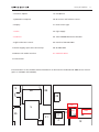
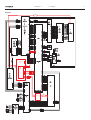
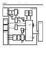
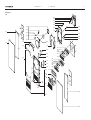
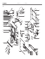
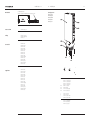
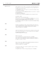
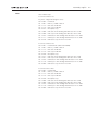
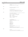
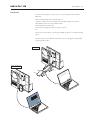
BeoSound 3200
Type 2681, 2682, 2683, 2684, 2685, 2686, 2687, 2690
Supplement
English, German, French, Italian, Spanish
illustration
CONTENTS
Survey of modules ..................................................................... 1.1
Diagrams etc ......................................................................................... 2
Wiring diagram .......................................................................... 2.1
Block diagram ............................................................................ 2.2
Available parts ...................................................................................... 3
Testmodes etc. ...................................................................................... 4
Dismantling .......................................................................................... 5
Service position .......................................................................... 5.1
Service tool ................................................................................ 5.2
Insulation test ....................................................................................... 6
This manual only contain the differences from the BeoSound 3000 to
the BeoSound 3200. All other documentation can be found in the
BeoSound 3000 manual.
Survey of modules
2 Interface f/µPH8
18 Headphone
3 µPH8 Microcomputer
20 IR receiver and left door sensor
5 Display
21 Door sensor right
7 Codec
28 Light supply
8 Stabiliser
86 Tuner-FM/AM-RDS-Stereo decoder
9 Light and motor control
89 Interface f/CD PRO MKII
12 Power Supply, Input select & Pre-amp.
90 CD PRO MKII
14 Master Link Audio interface
91 Hard Disk Drive
1.1
15 Transformer
Documentation on the modules marked with black can be found in the BeoSound 3000 service manual
(part no. 3538952 and 3538953).
9
90
89
28
Codec
PCB7
5
20
21
18
3
2
15
HDD
PCB91
14
Stabiliser
PCB8
86
12
Wiring diagram
2.1
2.1
Wiring diagram
2.1
Wiring diagram
6277686
SPDIF +
SPDIF -
P1003
PCB81
PCB90
6277384
SDA1
SCL1
AFL Codec
PCB 7
P4
USB
P2
SDA1
SCL1
HDD
PCB 91
6277724
L out
R out
GND
NC
NC
P3
P1
P16
6277724
GND
+ 12 V
GND
P2
Stabiliser
PCB 8
P1
6277724
GND
+ 12 V
GND
P122
Block diagram
2.2
2.2
Block diagram
2.2
Block diagram
Trafo PCB
+12V in
+12V
GND
GND
DC / DC
Voltage
Regulator
ON / OFF
+5V stby
Powersupply
LF board
CD-Player
Spdif
75 Ohm coax cable
FLASH SDRAM
UP Reset
Port
Expand
IIC
IIC (SCL & SDA)
IIC
CODEC PCB
+5Vd
+3.3V
+1.8V
+5Va
-5Va
Reset
IIC ON
Reset
Mute
Reset
IIC
Fs = 44.1 K
Level
Converter
Clock
33.868 MHz
Powersupply
LF board
Spdif
DSP
Harddisc
24.576 MHz
Spdif CLK
+5Vd
Div 2
GND
Sense
R In
R Out
L In
L Out
16.934 MHz
Differential
Amplifier
Buffer
Filter
+5V
Control
DAC
Reset Mute
IIS
Power
Supply
+1.8V
+3.3V
Available parts
3.1
3.1
Available parts
3.1
Available parts
Front
6
9023
6
9024
1
1
9025
9003
9024
9025
9027
1
9005
1
9
1
9002
6
9026
9004
9001
90
6
9021
9022
9024
9006
2
9025
2
9007
9027
2
7
2
9008
9005
9009
4
7
7
4
9011
9013
0501
0502
0503
05DP2
0504
9014
0505
9012
3
9010
9012
3
9013
9014
3
5
5
0501
0502
0503
05DP1
0504
0506
9015
3
9016
3
9017
3
3
89
9018
9019
3
9028
9020
9029
Available parts
Front
9001
9002
9003
9004
9005
9006
9007
9008
9009
9010
9011
9012
9013
9014
9015
9016
9017
9018
9019
9020
9021
9022
9023
9024
9025
9026
9027
9028
9029
3162622
3162830
2802056
3017028
2830111
3162652
3153031
2819251
3165027
3904213
3162461
8230100
3131356
3322145
3322137
2572045
7500270
2816257
2776761
3451770
2917025
2816235
2311045
3333017
2812132
3112418
2810254
3162623
3162831
Cover, left
Glass, left
Ring f/clamper with magnet strips
Wheel
Cylinder pin
Clamper
Clamper, complete
Spring
Cover f/clamper
Alu foil w/tape
Cover f/CD
PCB w/lamp
Light cabinet
Window
Window
Spacer
Contact spring
Ground spring
Set of buttons
Front piece, complete
Ball
Spring
Magnet top
Rubber damping
Compression spring
Chassis
Tension spring
Cover, right
Glass, right
05Module
0501
0502
0503
0504
0505
0506
8001362
8330286
7500272
2574079
3370148
3151285
3151292
Display
LED backlight module
Contact rubber
Rubber pad
Foil
Holder, upper
Holder, lower
05DP1
05DP2
8330259 Display, lower
8330468 Display, upper
09Module 8001550 Light and motor control
89Module 8001823 Interface f/CD PRO MKII
90Module 8420240 CD PRO MKII incl. pos. no. 9021, 9022 and 9023
Screws
1
2
3
4
5
6
7
2013144
2036036
2013118
2013172
2036085
2038118
2038133
Screw 3 x 8mm
Screw 2.5 x 4mm
Screw 3 x 8mm
Screw 3 x 6mm
Screw 2.5 x 6mm
Screw 3 x 6mm
Screw 3 x 11mm
3.2
3.2
Available parts
3.2
Available parts
3.3
3.3
Available parts
3.3
Chassis
27
3
8
32
9123
9
9101
27
9108
9162
3
91M1
9102
9102
10
10
11
11
12
11
9103
13
91M2
9109
9110
9111
10
9153
9112
13
13
9104
9105
9106
9107
27
9129
9163
12
9130
2001
19
27
17
17
1
9130
3
18
1
9131
2002
27
9148
3
20
2004
17
17
9132
2003
9154
17
20
9155
9149
1
14
12
9133
9114
8
28
3
3
15
9148
9157
30
8
9116
1
9116
1
9116
86
9160
9119
1
9151
35
36
1
9118
9142
9143
9135
7
23
9137
9138
23
33
35
33
33
9136
36
34
35
9147
23 23
24
25
24
25
9139
26
24 24
25 25
35
34
9145
9146
36
34
9159
1
9117
9144
34
30
9152
9134
9119
33
21
30
1
29
21
36
31
22
9115
3
31
29
9117
9158
9150
1
9117
9119
9119
2
8602
18
9119
28
8601
9115
9118
9156
1201
20
1
28
9148
3
9115
28
9140
26
26
26
23 23
26
9142
24
25
25
24
26
9143
9145
9144
9141
24
25
24
25
23
23
9137
9138
9139
Available parts
Chassis
9101
9102
9103
9104
9105
9106
9107
9108
9109
9110
9111
9112
9114
9115
9116
9117
9118
9119
9123
9129
9130
9131
9132
9133
9134
9135
9136
9137
9138
9139
9140
9141
9142
9143
9144
9145
9146
9147
9148
9149
9150
9151
9152
9153
9154
9155
9156
9157
9158
9159
9160
9162
9163
2722055
2831070
3151277
2732076
2722054
2700152
2819295
6276391
3035062
2819254
2700092
2854153
3114455
3947546
3152747
3103303
2642030
2311029
2732092
2815032
2311030
2548254
3010033
3031587
2810133
2810155
3955042
2391086
3152727
2391087
2548247
3013095
2391086
3152727
2391087
3035060
3013096
2548247
3030116
3358275
3358274
3152730
3124121
3430605
3164900
3151321
3300120
3031682
6100273
6100329
6100307
6100331
6100332
6100386
3031689
2560279
3152757
2755072
Belt pulley
Shaft
Holder
Belt
Belt pulley
Gear wheel, complete
Spring
Wire w/switch
Slide shoe
Spring
Gear wheel
Arm
Chassis incl. pos. no. 9117, 9118, 9119, 9133 and 9152
Copper tape - 16.5m
Wire holder
Foot
Clamp
Clip
Belt
Leaf spring
Clip
Bracket
Stop f/transport screw
Bracket
Tension spring
Spring
Cord
Locking piece
Holder
Locking piece
Bracket
Guide rail incl. pos. no. 9137, 9138 and 9139
Locking piece
Holder
Locking piece
Slide shoe
Guide rail incl. pos. no. 9142, 9143, 9144 and 9145
Bracket
Hinge
Heat sink
Heat sink
Holder
Mounting plate
Rear cover
Cable cover
Strap
Screen
Frame
Mains cable, type 2681-2690 (EU-LAT)
Mains cable, type 2682 (GB)
Mains cable, type 2683-2686 (USA-CDN-TWN)
Mains cable, type 2684 (JPN)
Mains cable, type 2685 (AUS)
Mains cable, type 2687 (KOR)
Holder f/PCB3
Rail
Holder f/antenna
Gearbox, complete
91M1
91M2
8400190 Motor
8400189 Motor
02Module 8006796 Interface f/µPH8
03Module 8000909 Microprocessor
IC3
8344212 APP SW
IC6
8343712 EEPROM
3.4
3.4
Available parts
3.4
07Module 8420268 HDR-A Kit, complete
08Module 8100096
3153037
2038149
3947613
Back-up, complete
Holder
Screw 3 x 8mm
Foamtape
12/14/15Module
8000913 PCB12/14/15 EU, complete
8000914 PCB12/14/15 US, complete
3152799 Holder
Sockets, see wiring diagram
1201
18Module 8001817 Headphone
20Module
2001
2002
2003
2004
8005738
3300124
3300123
3304135
3300129
IR receiver and left door sensor
Screen, inner
Screen, outer
Shielded box
Screen
91D1
91D2
91D3
6277348 Wire - Plug with reception diode
6277061 Wire - Plug with transmitter diode, left
6277061 Wire - Plug with transmitter diode, left
21Module 8006799 Door sensor right
91D4
91D5
91D6
6277348 Wire - Plug with reception diode
6277118 Wire - Plug with transmitter diode, right
6277118 Wire - Plug with transmitter diode, right
28Module 3358279 Light supply
Screws, washers etc.
86Module 8006800
8006801
8601
3031683
8602
3031684
Tuner-FM/AM-RDS-Stereo decoder EU/US
Tuner-FM/AM-RDS-Stereo decoder JAP
Bracket f/PCB86, right
Bracket f/PCB86, left
1
3
8
9
10
11
12
13
17
18
19
20
21
22
23
24
25
26
27
28
29
30
31
32
33
34
35
36
Screw 3 x 8mm
Screw 3 x 8mm
Solder tag
Screw 2.2 x 4.5mm
Bushing
Spacer
Lock washer
Screw 2.6 x 6.5mm
Screw 3 x 8mm
Screw
Washer
Nut
Nut
Screw 3 x 8mm
Screw 2.5 x 2.7mm
Cord pulley
Rivet
Screw 3 x 8mm
Screw 3 x 10mm
Screw 3 x 12mm
Screw 3 x 5mm
Screw 3 x 8mm
Washer
Screw 3 x 20mm
Screw 4 x 10mm
Washer
Rubber bushing
Bushing
2013144
2013118
7530119
2011310
2938237
2930074
2390001
2036061
2038149
2013218
2625002
2389064
2380145
2058017
2036066
2724078
2364019
2011050
2038094
2039064
2039062
2039035
2622052
2039014
2042076
2622024
2938277
2930106
Available parts
Wire bundles
See wiring diagram page 2.1
The part no. is printed on the diagram above the wire bundle, as shown.
Parts not shown
3657455 Product cover
Packing
3392405 Outer carton
3397824 Foam packing
3946038 Foil
User’s Guide
3508588
3508589
3508590
3508591
3508592
3508593
3508594
3508595
3508596
3508597
3508598
3508599
3508600
3508601
3508602
Danish
Swedish
Finnish
English
German
Dutch
French
Italian
Spanish
Portuguese
Greek
Russian
Japanese
Taiwanese
Korean
Supplement
3504709
3504710
3504711
3504712
3504713
3504714
3504715
3504716
3504717
3504718
3504719
3504720
3504721
3504722
3504723
Danish
Swedish
Finnish
English
German
Dutch
French
Italian
Spanish
Portuguese
Greek
Russian
Japanese
Taiwanese
Korean
3.5
3.5
Available parts
3.5
Stand, type 2051
1205111, silver
1205194, green
1205196, black
1205198, blue
1205199, red
9501
9502
9503
9504
9505
3451589
3451591
3451592
3451593
3451594
3458890
2752043
3013094
3013094
Cover plate, silver
Cover plate, green
Cover plate, black
Cover plate, blue
Cover plate, red
Cover plate
Bottom
Guide rail, right
Guide rail, left
a
b
c
c
3103390
3103392
2046040
2046041
Foot, spike
Foot, soft
Screw 6 x 63mm
Screw 6 x 66mm
3502921 Setting-up guide
3397953 Foam packing
3392423 Outer carton
Available parts
Center wall bracket, black, type 2052
1205266
9510
9511
9512
9513
2777061
1205266
2038130
2043016
2930126
Handle, right and left
Wall bracket
Screw 3 x 25mm
Screw 4 x 10mm
Bush
3390432 Wire holder
3502922 Setting-up guide
3.6
3.7
Available parts
System wall bracket, black, type 2087
1208766
9520
9521
9522
9523
9524
9525
9520
9521
9522
9523
9524
9525
3152790
2039014
2777061
2038130
3031319
1208726
Holder f/antenna
Screw 3 x 20mm
Handle, right and left
Screw 3 x 25mm
Wall plate
System wall bracket, complete
3390341
3390432
3502996
3392185
3397774
Screw assortment
Wire holder assortment
Setting-up guide
Outer carton
Foam packing
Available parts
Floor center stand – type 2068
9201
9207
9202
Incl. pos. no. 9201
9203
9204
9205
Incl. pos. no. 9210
9207
9210
9211
9201
9202
9203
9204
9205
9207
9210
9211
2993045
3459259
2950217
3459258
2752082
2044064
3103392
3103390
Pin
Top plate incl. pos. no. 9201
Aluminium tube
Cover plate
Foot incl. pos. no. 9210
Screw M5x20mm
Foot “soft”
Foot “spike”
3390615
3504636
3392709
3396132
Bag incl. 4 pcs. of 9207, 6 pcs. of 9211 and 1 allen key
Setting-up guide
Outer carton
Foam packing top/bottom
3.8
Testmodes, English
4.1
TM (test mode) names/function for adjustments and service
Tuner test modes
TM 01: Automatic offset-adjustment for FM
TM 02: Manual offset-adjustment for FM
TM 03: Status for offset-adjustment
TM 04: Variant status
TM 06: Check RDS name
TM 07: Setting up of tuner variant
Master test modes
TM 20: Test of display functions
TM 21: Open ML-out
TM 22: Test of keyboard functions
TM 23: Software version
TM 24: Service operation counter
TM 25: Open ML-in
TM 27: Service of error detection
TM 28: Validity test for ROM/RAM/EEPROM
TM 31: Set default settings
(TM 31 defaults all CD settings, radio settings and deletes all tracks from CD MEM!)
TM 32: Read-out of product ID
TM 34: Read-out of options
TM 35: Power down ON
TM 36: Power down OFF
TM 37: Set default settings
(TM 37 does not default CD MEM)
CD test modes
TM 61: Focus on
TM 62: Focus off
TM 63: Starts turntable motor
TM 64: Stops turntable motor
TM 65: Light pen to outermost position
TM 66: Light pen to the innermost position
TM 67: Starts CD
TM 68: Stops CD
TM 70: Updates tracklist in EEPROM
TM 71: Power on the CODEC module
TM 78: Dump HDD serial number to EEPROM (used at replacement of the HDD)
Test mode activating
Wait 20 - 30 sec. after connecting to mains.
By means of keyboard from St.by mode: Press Display 0 2 5 8 with no more than
2 sec. between the individual enterings.
By means of remote control from St.by (can only be done if the product is not in
option 0) :
Press SHIFT 9 0 2 5 8 with only 2 sec. between.
The remote control has to be in RADIO or CD option.
In TM the tuner is fully functional and may overwrite the display but the TM will
continue.
Deactivating
Press • and the display shows “TM OFF” or disconnect from mains.
4.2
Testmodes, English
Glass doors lock
When the glass doors are locked it is not possible to open them by magic open.
The glass doors can only be locked if the product is in St. by, the glass doors are
closed and only by remote control.
Press SHIFT 9 0 3 6 9 with no more than 2 sec. between the individual entering.
The display shows “LOCKED”.
To unlock the glass doors press SHIFT 9 0 3 6 9 with no more than 2 sec. between
the individual entering.
The display shows “UNLOCKED”.
The function will be remembered in NVRAM after disconnecting from mains.
-
From TM01 to TM09.
Wait 20 - 30 sec. after connecting to mains.
By keyboard from St.by mode: Press Display 0 2 5 8 RADIO with no more than
2 sec. between the individual entering. Then key in the TM no.
By remote control from St.by (can only be done if the product is not in option 0):
Press SHIFT 9 0 2 5 8 with no more than 2 sec. between the individual entering.
Then key in TM no.
TM01
Automatic offset-adjustment for FM is done by letting the tuner search for the
frequency 100 MHz (84 MHz for Japan) and when the signal is found the offset
will be calculated and stored in NVRAM. The display shows “A OFFSET”.
If failure the display shows “TM ERROR”.
TM02
Manual offset-adjustment for FM is done by key-in a frequency. The tuner search
tunes for this frequency and the offset will be calculated and stored in NVRAM.
The display shows “M OFFSET”.
If failure the display shows “TM ERROR”.
TM03
Read-out offset status.
If the offset-adjustment is needed the display shows “TM ERROR”.
If the result of the offset-adjustment is positive the display shows “OFFSET n”.
If the result of the offset-adjustment is negative the display shows “OFFSET -n”.
The figure n is in steps of 12.5 kHz.
TM04
Read-out variant status: EUROPA (EU) FM, EUROPA (EU) FM/AM, USA (US) and
JAPAN (JP). The display shows e.g. “EU FM/AM”.
If failure the display shows “TM ERROR”.
TM06
Checking that the RDS name of the radio programme in question is RDS-PS.
The display shows “TM OK”.
If wrong RDS name or if name is missing the display shows “TM ERROR”.
Testmodes, English
TM07
Tuner variant setup:
If from EU or AUS to US:
Key in the 3 digits indicating the choice.
No. 0: 003 = variant US
No. 1: 001 = RDS on, or 000 = RDS off
No. 2: 175 = FM starts in 500 kHz
No. 3: 216 = FM stops in 500 kHz
No. 4: 075 = Deemphas in µs
No. 5: 000 = LW starts in kHz dividing with AM raster. 0 if no LW
No. 6: 000 = LW stops in kHz dividing with AM raster. 0 if no LW
No. 7: 053 = MW starts in kHz dividing with AM raster. 0 if no MW
No. 8: 171 = MW stops in kHz dividing with AM raster. 0 if no MW
No. 9: 010 = AM raster. Steps in kHz. 0 if no AM
If from US or AUS to EU.
No. 0: 001 = variant EU FM. (002 if EU FM/AM)
No. 1: 001 = RDS on, or 000 = RDS off
No. 2: 175 = FM starts in 500 kHz
No. 3: 216 = FM stops in 500 kHz
No. 4: 050 = Deemphas in µs
No. 5: 017 = LW starts in kHz dividing with AM raster. 0 if no LW
No. 6: 031 = LW stops in kHz dividing with AM raster. 0 if no LW
No. 7: 058 = MW starts in kHz dividing with AM raster. 0 if no MW
No. 8: 179 = MW stops in kHz dividing with AM raster. 0 if no MW
No. 9: 009 = AM raster. Steps in kHz. 0 if no AM
If from EU or US to AUS
No. 0: 005 = variant AUS
No. 1: 001 = RDS on, or 000 = RDS off
No. 2: 175 = FM starts in 500 kHz
No. 3: 216 = FM stops in 500 kHz
No. 4: 050 = Deemphas in µs
No. 5: 000 = LW starts in kHz dividing with AM raster. 0 if no LW
No. 6: 000 = LW stops in kHz dividing with AM raster. 0 if no LW
No. 7: 058 = MW starts in kHz dividing with AM raster. 0 if no MW
No. 8: 179 = MW stops in kHz dividing with AM raster. 0 if no MW
No. 9: 009 = AM raster. Steps in kHz. 0 if no AM
4.3
4.4
Testmodes, English
TM20
Checking the display by showing 3 types of letters in 3 rounds until all pixels are
used/tested.
Press PLAY to shift between icons in the display.
TM21
Opens the signal from AUX-plug to the ML-output.
The display shows “AUX 2 ML”.
TM22
Test of key-board functions.
By pressing a key for instance CD the display will show “CD”.
The testmode can only be ended by IR-remote control command “STOP”.
This testmode can only be activated by IR-remote control command.
TM23
Before activating TM23, right after have connected the mains, you need to activate
all sources (radio, CD and CD MEM).
Read out of Software version. Press PLAY to continue.
AP xx.xxx
= Application processor. (Main CPU)
OS xx.xxx
= APOS
IO xx.xxx
= I/O processor
TU xx.xxx
= Tuner processor. (Tuner-FEP)
CD xx.xxx
= CD processor. (CD-FEP)
CDM xx.xxx = PPI CODEC
TM24
-
Service running counter.
First the Stand-by time will appear.
Press PLAY to toggle between the different counters.
St. by time
Radio-mode time
CD-mode time
CD MEM-mode time
AUX-mode time
N.Radio-mode time
N.Music-mode time
ML active time
Theft protection active time
Number of times the theft protection has been unlocked.
CD Copy-active time
All numbers are stated in interval of 10. (e.g. 3 = 30.)
When all counters have been shown the display will ask for a new test mode.
TM25
Opens ML-in.
A source must be selected to have a correct measurement.
Signal coming from the ML-in, exit on the PL and AUX as by normal selection.
Testmodes, English
4.5
TM27
-
Service Error detection.
The last registred errors regarding EEPROM, ML, IIC-bus, RS232 driver, CD and lids
can be read-out. This test mode is also used for deleting all error-registrations.
To toggle between error indications press PLAY. When all errors are read press
PLAY to reset all errors registered or press STOP to keep error register.
By pressing m or p the time for errors will be shown.
YY.MM.DD
hh.mm.ss.
MEM: last EEPROM error.
2: EEPROM writes error
3: EEPROM reads error
4: EEPROM reads error only FF
11: EEPROM writes owerflow
12: EEPROM controls init fail
13: EEPROM controls calloc fail
99: EEPROM content error
ML: Last error regarding to ML.
- 8: Link tied down
- 16: Link tied up
- 32: Configuration impossible
IIC: Component which gave the last error regarding IIC-bus.
- 102: Tuner FEP
- 136: Sound Processor
- 208: Clock
-
SER: The last error from the RS232 driver.
02: CDA queue not attached
03: CDA error timeout
04: CDA error unknown buf addr
05: CDA error data expected
06: CDA error unknown CMD
07: CDA error checksum
08: CDA error RX timeout
09: CDA error out of buffers
10: CDA error uart overrun
11: CDA error uart framing
12: CDA error uart parity
CD: CD error.
- 2: Focus error
The CD could not focus within the time limit.
- 3: Radial error
Set when the CD did not get on track after several retries.
- 4: Turntable motor error
Set when the disc did not spin up or down within the limit.
- 5: PLL lock error
Set when PLL is out of lock during tracking mode.
- 6: Jump error
Set when a seek could not be performed or an error occured during a binary search.
- 7: Subcode error
Set when a subcode could not be read within the time limit.
4.6
Testmodes, English
- 8: TOC read error
Set when the TOC could not be read, no access possible to lead-in.
- 20: Serial communication overrun error
Expected command byte, but received a data byte.
- 22: Serial communication noise error
Check did not match.
- 23: Serial communication software error
Queue full.
- 37: Selection error
-
OS: Error in the operation system.
07: IL TLG from FEP to APOS
08: IL TLG from APOS to FEP
09: IL RX TX BUF limit
13: FEP does not exist
-
IO: Last error in the I/O driver.
01: IIC1 2 error
05: Cannot configure FEP
06: FEP communication error
07: IL TGL from FEP to APOS
08: IL TGL from APOS to FEP
09: Interlink RX TX BUF limit
14: FEP does not exist
21: MLSL timeout error
22: MLSL TX BUF full TLG does not send
23: ML key lost key repaired
24: External communication not allowed in preproject
25: LSL format error
26: LS IR format error
27: LSL TX imposs
28: LSL link tied up
29: LSL link tied down
30: Generic ICB error
31: ICB L7 timeout
32: ICB L7 illegal timeout
33: ICB L7 out of repositories
34: ICB L7 illegal L7 ack
35: ICB L7 Acknowledge unexpected
36: ICB L7 read response unexpected
37: ICB L7 illegal resource type
38: ICB L7 resource still running
39: ICB L7 resource already free
40: ICB L7 illegal IOP service
41: ICB L7 illegal IOP object
42: ICB L7 telegram flushed
43: ICB L7 resource disabled
44: ICB L7 HW clock illegal command
45: ICB L7 HW clock illegal event
46: ICB L2 retrans limit reached
47: IIC component disabled
48: Power down of IOP impossible
49: CDS bus disabled
Testmodes, English
-
AP: Last error in the main micro-processor.
16: Illegal timer ID
17: Timer not free
21: Illegal date value
22: Illegal time value
23: Illegal timer parameters
32: Illegal simple message ID
33: Out of message buffers
34: Message buffer virtual limit reached
64: Non ISR func. called from ISR
65: Physical stack limit reached
66: Stack virtual limit reached
67: Out of IAS objects
68: IAS signal lost
69: Overflow in IAS FIFO
70: IR queue not attached
71: LSL queue not attached
72: Scan queue not attached
73: Active keyscan queue not attached
74: Uart 0 queue not attached
75: TIIC queue not attached
76: RIIC queue not attached
77: Out of power down callback OBJ
78: Power down entered with timer running
79: Watchdog reset
-
IOP: Last error in the I/O microprocessor.
01: Watchdog reset
02: ICB layer 2 timeout
03: ICB layer 7 illegal service
04 ICB layer 7 illegal object
05: Reg mem data frame not valid
06: Data frame not valid
07: Illegal port ID
08: LSL TX impossible
09: LSL tied up
10: LSL tied down
11: IIC slave buffer full
12: IIC slave transmit timeout
13: IIC illegal switch port
14: IIC2 slave addressed
15: IIC conditional polling timeout
16: IOP IIC error
17: PD entered while service waitning
18: TP ICBL7 illegal command
19: TP module HW error APOS
21: TP clock error APOS
4.7
4.8
Testmodes, English
-
CD MEM: Last error in CD MEM
00: No error
01: Illegal command
02: Illegal group id value
03: Illegal cd id value
04: Illegal track id value
05: Execution error
06: Command not allowed now
07: Operation not allowed now
08: Illegal name
09: Bad song
10: Record failure
11: Illegal return code
16: HDD format error
17: HDD internal error
18: HDD access error
19: HDD copy failure
20: HDD move error
21: HDD bin full
22: HDD delete error
23: HDD defragment error
TM28
This TM checks the function of ROM, RAM, EEPROM. (O, A, P).
To readout TM, O and A have to be (+).
E.g. MEM ++- indicates error in the EEPROM.
TM31
(During TM31, do not disconnect the mains before “OK” is displayed. This can take
several minutes).
Default settings for sale purpose.
Option:
1
Volume:
32
Balance:
0
Bass:
0
Treble:
0
Loudness: OFF
Radio programs erased.
(TM37 is simular, but does not
CD settings erased.
contain the CD MEM step)
CD MEM erased (all tracks is deleted)
Timer settings erased.
After default settings the display shows DEFAULT TM ERROR.
If error occurs in TM the display will show TM ERROR.
Item-number, serial-number, type-number, master pin-code, running counter and
all offset adjustments will not be erased.
!
TM32
ID-readout of the product.
Press PLAY to toggle between the ID-numbers.
Item = 7 figures.
Type = 4 figures.
Serial = 8 figures.
MA PIN = OK or ERR.
If error in the readout all figures = 0.
Testmodes, English
4.9
TM34
Option readout.
TM35
Power down ON.
When power down mode is possible the display = TM OK.
TM36
Power down OFF.
When power down mode is not possible the display = TM OK.
TM37
Default settings for sale purpose.
Option:
1
Volume:
32
Balance:
0
Bass:
0
Treble:
0
Loudness: OFF
Radio programs erased.
CD settings erased.
Timer settings erased.
After default settings the display shows DEFAULT TM ERROR.
If error occurs in TM the display will show TM ERROR.
Item-number, serial-number, type-number, master pin-code, running counter and
all offset adjustments will not be erased.
To use CD test modes it is necessary to select CD, in the TM the HF-signal will not be used
TM61
Focus ON.
The CD-pen will try to focus.
This TM can only be turned off by using TM62.
TM62
Focus OFF.
The CD-pen will be turned OFF.
TM63
Starts turntable motor.
This TM can only be turned off by using TM64.
TM64
Turns off the turntable motor.
TM65
Light pen to outermost position.
The optical pickup unit goes to the outermost position and stays there.
This TM can only be turned off by TM66. Do not give other commands in the
meantime.
TM66
Light pen to the innermost position.
The optical pickup unit goes to the innermost position and stays there.
4.10
Testmodes, English
TM67
The CD starts playing.
TM68
The CD stops playing.
When error in CD-TM the Error-number refers to TM27 CD-errors.
TM70
Updates tracklist in EEPROM (is used when HDD is replaced).
(Can take several minutes, depending on the amount of recorded material).
TM71
CODEC power on.
Is used to power up the CODEC module when the module is flash updated.
The display show “FLASH” during the testmode.
TM78
Store HDD serial number in EEPROM.
(Is used after replacement of the HDD).
Service position
BeoSound 3200 in service position
1
2
8x
7x
5.1
Service tool
5.2
Service tool
This is a short description of the service tool, a full description will follow the
HDR-A kit.
When ordering a HDR-A kit you will be able to:
Copy the contents from the old HDD to the new (depending on the defect)
Flash update the PPI sw on the CODEC module
Outread the HDD serial number
Format every single group (red, blue, yellow or green)
Etc.
All actions is performed by connecting the CODEC module to a computer via USB
cable.
All cables will follow the HDR-A kit (and the service tool program is downloaded
from the Retail System).
Copying
Flash-updating
Slave
(new unit)
Master
(old unit)
0
32
d
un
o
e
ar
oS
w
Be
ft p
So ku
u
e ac
t
en
b
a
M
pd A
U RD
1. H . .
2. . . . .
3. . .
4.
0
I/O
00
32
nd
e
u
r
o
a
oS
w
ft p
Be
So ku
u
e ac
en
at
M
d Ab
p
U RD
1. H . .
2. . . . .
3. . .
4.
I/O
Isolations test, English - German
6.1
Insulation test
Each set must be insulation tested after having been dismantled.
Make the test when the set has been reassembled and is ready to be returned to
the customer.
Flashovers must not occur during the testing procedure!
Make the insulation test as follows:
Short-circuit the two pins of the mains plug and connect them to one of the
terminals of the insulation tester. Connect the other terminal of the insulation
tester to the chassis pin of the headphone socket.
NOTE!
To avoid damaging the set it is essential that both terminals of the insulation tester
have good contact.
Slowly turn the voltage control of the insulation tester until a voltage of 2.5kV and
max. 10mA is obtained. Maintain that voltage for one second, then slowly turn it
down again.
Isolationsprüfung
Nach der Zerlegung muß bei jedem Gerät eine Isolationsprüfung vorgenommen
werden.
Prüfung vornehmen, wenn das Gerät zusammengebaut und zur Auslieferung an
den Kunden bereit ist.
Während der Prüfung dürfen keine Überschläge auftreten!
Isolationsprüfung folgendermaßen vornehmen:
Beide Stifte des Netzsteckers kurzschließen und mit einer der Klemmen des
Isolationsprüfers verbinden. Andere Klemme des Isolationsprüfers am
Masseanschluß der Kopfhörerbuchse anschließen.
ACHTUNG!
Um Beschädigungen des Geräts zu vermeiden, müssen beide Klemmen des
Isolationsprüfers unbedingt einen einwandfreien Kontakt haben.
Spannungseinstellung des Isolationsprüfers langsam auf eine Spannung von 2,5 kV
und max. 10mA erhöhen. Diese Spannung eine Sekunde beibehalten, anschließend
langsam verringern.