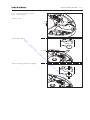
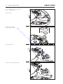
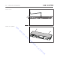
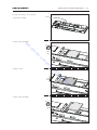
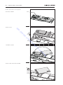
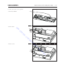
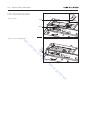
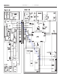
1
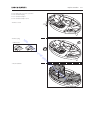
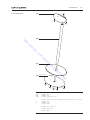
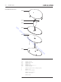
BeoCenter 2 Audio
TypeMaster Unit 2802
TypeSocket Unit 2839, 2840, 2841, 2842, 2843, 2844, 2845, 2846, 2847
Service Manual
English
German, French, Italian, Spanish, Danish, Dutch and Japanese versions
are available in the Retail System
O
AB
R
TE
EN
-C
RI
EN
H
v/
S
N
E
KS
RO
KT
E
EL
IK
N
This Service Manual must be returned
with the defective parts/back-up suitcase !
CONTENTS
Survey of modules ......................................................................................... 1.1
How to service ............................................................................................... 1.2
PIN-code ........................................................................................................ 1.4
Warnings ....................................................................................................... 1.6
Adjustments .................................................................................................. 2.1
Service menu ................................................................................................. 3.1
Service tips .................................................................................................... 4.1
AB
Replacement of modules ............................................................................... 5.1
O
Specification guidelines for service use ........................................................... 6.1
EN
-C
Overall blockdiagram ..................................................................................... 7.1
TE
Wiring diagram . ............................................................................................ 7.3
R
RI
EN
H
v/
Available parts ............................................................................................... 8.1
S
N
E
KS
RO
KT
E
EL
IK
N
Survey of modules 1.
BeoCenter 2 Audio – Master Unit
5
9 4
2
77
95
O
AB
R
TE
EN
-C
PCB2
PCB4
PCB5
PCB9
PCB77
PCB95
RI
EN
H
v/
Top Interface
IR receiver two (right)
IR receiver one (left)
Display
CD Main Board Assy
CD Traverse Mechanism
E
KS
S
N
BeoCenter 2 Audio – Socket Unit
RO
KT
1
E
EL
60
50
6
IK
N
PCB1
PCB6
PCB37
PCB50
PCB60
PCB85
AV panel DAB
µP H8-4
DAB module
Analog sound engine
SMPS
Tuner EU/US/JPN
85
37
1. How to service
How to service
Front line service
Both the Master and the Socket Unit has been developed for simple module
exchange to follow the on-site service strategy. Module exchange is possible on-site,
at the dealer or in the service workshop whatever is most convenient in each case.
For on-site service a back-up suitcase must be used.
Module exchange is the recommended way to perform service, due to the fact
that most of the modules are multi layer based, and most of the circuits are on a
single main PCB.
An electrical fault symptom can be removed during one visit to the customers
home if you bring a BeoCenter 2 back-up suitcase with you.
Is it a mechanical symptom, the particular part must be brought with you
separately.
O
AB
TE
EN
-C
Service documentation
The Socket Unit and the Master Unit must be connected when testing, because
the Socket Unit contains the power supply.
R
Service documentation for BeoCenter 2 Audio will be a Service Manual with part
nos. for the back-up suitcase, electrical and mechanical parts, user’s guides etc.
RI
EN
H
v/
S
N
E
KS
RO
KT
E
EL
IK
N
How to service 1.
Converting mains voltage supply
The Master Unit has only one variant for all markets.
The Socket Unit has separate type nos. for each market, due to country approvals.
The mains voltage is determined by the type nos. of the Socket Unit, there are
only two internal mains voltage settings (a jumper) on the SMPS, 100/120V and
230/240V AC. (X103, when mounted = 100/120V).
For tuner setup use the Service Tool for reprogramming.
The only variant on the Master Unit : 2802
The variants on the Socket Unit :
O
AB
R
TE
EN
-C
RI
EN
H
v/
E
KS
S
RO
KT
E
EL
Market
Austria, Azerbaijan, Belgium,
Bulgaria, Croatia, Czech Repub., Denmark, Egypt, Estonia, Faroe Islands, Finland, France,
Germany, Greece, Greenland, Holland, Hungary, Indonesia, Iceland, India, Israel, Italy, Kazakhstan, Latvia, Lebanon,
Liechtenstein, Lithuania, Malaysia,
Morocco, Norway, Oman, Pakistan,
Poland, Portugal, Qatar, Romania, Russia, Saudi Arabia, Serbia,
Singapore, Slovak Rep., Slovenia, Spain, St. Martin, Sweden, Switzerland, Thailand, Turkey, Ukraine, Uzbekistan
Bahrain, Botswana, Dubai, Ghana, Hong Kong, Ireland, Kuwait, Nigeria,
South Africa, UK, United Arab Emirates
Brazil, Caribbean Islands, Canada, Mexico, Panama, USA
Japan
Australia, New Zealand
Taiwan
Korea
Argentina, Chile, Peru, Uruguay
China
IK
N
Mains Voltage
230V/240V
230V
120V
100V
240V
110V
110V
230V
230V
N
Type no.
2839
2840
2841
2842
2843
2844
2845
2846
2847
1. PIN-code
PIN-code
The product has a 4 digit PIN-code, of the user´s own choice, which must be entered
if the product has been disconnected from the mains for 15-30 min.
If the PIN-code is activated, and the product has been without mains for 15-30 min.,
the user will be asked to enter the 4 digit PIN-code when the product is switched on.
Before the product is handed in to service it is a good idea to ask the customer to
deactivate the PIN-code.
The PIN-code is activated when the product is shipped from Bang & Olufsen.
Refer to the user guide for further information.
PIN-code active prior to service
EN
-C
Service code
O
AB
If the PIN-code is not deactivated prior to service you must use the Service code to
unlock the product.
R
TE
-
-
The service code,
unlocks the product, but does not affect the pin-code setting
gives you 12 hours service time
v/
Entering the Service code
RI
EN
H
1. When the product asks for PIN-CODE press and hold l for 3 seconds.
2. The Master code menu appears.
3. Enter the Service code: 1 1 1 1 1.
E
KS
Important notice concerning Service time
N
S
The service time is active as long as the product is connected to the mains, including
Standby.
E
EL
RO
KT
To obtain maximum service time:
Only connect the product to the mains while you are performing actual service on
the product.
IK
N
When the service time is expired, the product can only be unlocked by entering
the PIN-code or the Master code.
Registration of the modules
-
-
The modules will be registered to the product in the following situations:
the product has been connected to the mains for more than 12 hours, including
Standby time.
the PIN-code is activated or deactivated.
PIN-code deactivated by
customer prior to service
-
-
With the PIN-code deactivated prior to service you must be aware of the modules
will be registered to the product in the following situations:
the product has been connected to the mains for more than 12 hours, including
Standby time.
the PIN-code is activated or deactivated.
The registration of modules in the product can only be changed at Bang & Olufsen.
PIN-code 1.
Activate the PIN-code
Select the SETUP menu.
Press l twice and then STOP to bring up the PINCODE SETUP menu.
Enter the 4 digit Pin-code. Re-enter the code to confirm it and press GO.
If you want to change or delete the PIN-code, enter the correct PIN-code and press GO.
It is now possible to change the PIN-code or delete the PIN-code.
Enter the PIN-code
If the PIN-code is activated and the product is disconnected from the mains for
more than15-30 minutes, a PINCODE menu appears as soon as the product is
switched on.
Enter the PIN-code, and the product starts again.
If the PIN-code has been forgotten
O
AB
R
TE
EN
-C
If the PIN-code has been forgotten the only way to unlock the product again is by
entering a 5 digit Master-code.
The Master-code is ordered by sending a request via the Retail System.
When the product prompts for a PIN-code, press and hold l down to bring up the
MASTERCODE menu.
Enter the Master-code and press GO. This will deactivate the PIN-code and
reactivate the product.
v/
Product locked by PIN-code
The PIN-code is activated and the mains is disconnected for more than 15- 30
minutes.
RI
-
EN
H
The product is locked by PIN-code when:
E
KS
The product is unlocked when the PIN-code is entered.
S
N
RO
KT
E
EL
The PIN-code counter is set to 5 attempts within 3 hours.
When a wrong PIN-code has been entered 5 times within 3 hours, the product
cannot receive any commands for a period of 3 hours.
After this period the PIN-code counter is reset.
The product must be in standby mode to activate the timer.
IK
N
1. Warnings
Warnings
ESD
STATIC ELECTRICITY
MAY DESTROY THE
PRODUCT
When electrical replacements or disassembly is taking place, use a ESD-mat. The
internal electronic are very sensitive to static electricity.
When mains voltage on the BeoCenter 2 is required, remove the connection from
the BeoCenter 2 to the ESD mat.
Laser exposure
The BeoCenter 2 contains a laser system and is classified as a class 1 laser product.
The BeoCenter 2 must only be opened by qualified personal only.
O
AB
General Warnings
EN
-C
Wear cotton gloves to avoid placing fingerprints on the product.
R
TE
The aluminium and display surface on the product is very sensitive, so handling
should be done with great care to avoid damage. When transporting the
BeoCenter 2 it is recommended to use the product cover, part no. 3375021.
v/
E
KS
Cleaning
RI
EN
H
The interface cable is very sensitive to sharp bends and other large mechanical
influence. Also be sure that the plugs in each end, are connected correctly.
Clean the BeoCenter 2 surfaces using a lint-free cloth which you have wrung
firmly in lukewarm water.
S
N
RO
KT
Lithium battery
E
EL
Never use alcohol or other solvents to clean any parts of the BeoCenter 2.
IK
N
WARNING
Short-circuit and overcharging of some types of lithium batteries may result in a
violent explosion.
Adjustments
2.
Adjustments
Digital Audio Broadcasting
(DAB)
The DAB module (type 2203) for the BeoCenter 2 Socket Unit will automatically
adapt to the band and frequency table preprogrammed in the application software
for the particular Socket Unit type number. If the band and frequency table setup
from the factory do not correspond to the particular country where it is used, the
PC-based ServiceTool program must be used.
DAB aerial
Select a channel transmitting a DAB mutiplex signal. Position the aerial to maximum
signal level.
O
AB
Keyboard: Press “LIST” p select “SETUP” n “RADIO” p “DAB AERIAL ADJUSTMENT”
then press GO.
TE
EN
-C
Beo4 remote control: Press “MENU” p select “SETUP” n “RADIO” p “DAB
AERIAL ADJUSTMENT” then press GO.
R
Watch the indicator bar on the display while adjusting the DAB aerial. The white
fields indicates minimal risk of signal drop-out.
H
v/
DAB DRC
RI
EN
Dynamic Range Control “DRC” appears in the lower right-hand corner of the
display if transmitted with the DAB program and DRC is not set to OFF. DRC in
nominal ‘NOM’ or ‘MAX’ position reduces the signal level between the weakest
and the strongest signal and thereby compensates for disturbance from the
surroundings. See more information in the Users guide.
S
N
E
KS
RO
KT
E
EL
IK
N
2.
O
AB
R
TE
EN
-C
RI
EN
H
v/
S
N
E
KS
RO
KT
E
EL
IK
N
Service menu
3.
Service Menu
There are two ways to enter the service menu, either by the keyboard or the Beo4
remote.
Keyboard: With the BC2 turned on, press “list” -> “Setup” then press n and
within 3 sec. Press 0 0 GO.
Beo4 remote: With the BC2 turned on, press “menu”-> “Setup” then press n and
within 3 sec. Press 0 0 GO.
Note you have entered the service menu, and have the following options:
O
AB
R
TE
EN
-C
H
v/
.. Service Menu
1 SW Versions…
2 Error List…
3 Product ID…
4 Service Counters…
5 Default Settings
6 Keyboard Test…
7 Loader Lock
8 DVD Service
9 DAB service display
10 Max. Volume
RI
EN
Select wanted menu using general menu navigation rules.
E
KS
1. SW Versions
3.61a
16.20a
1.10a
22.00a
1.00a
1.9-4
3.20a
S
N
RO
KT
E
EL
...SW Versions
1 AP
2 OS
3 AP Boot
4 IOP
5 FM Tuner
6 DAB Tuner
7 Master Unit
IK
N
2. Error List
Select from the list NVMEM errors or VMEM errors.
...Error List
1 NVMEM
2 VMEM
The NVMEM and the VMEM menu has the same layout, each menu will display
the last 15 errors. 1 is NVMEM (non volatile memory) and 2 is VMEM (volatile
memory). The errors in NVMEM are stored permanently, and can be used if BC2
has been disconnected from mains after an error has occurred. The VMEM only
stores errors that have occurred after BC2 has been connected to the mains.
3.
Service menu
O
AB
...NVMEM
1 4F 00000002 10/11/02…
2 08 16000000 9/11/02…
3 4F 00000002 8/11/02…
4 08 16000000 7/11/02…
5 4F 00000002 7/11/02…
6 08 16000000 6/11/02…
7 4F 00000002 5/11/02…
8 08 16000000 5/11/02…
9 4F 00000002 4/11/02…
10 .. ........ --/--/--…
11 .. ........ --/--/--…
12 .. ........ --/--/--…
13 .. ........ --/--/--…
14 .. ........ --/--/--…
15 .. ........ --/--/--…
R
TE
EN
-C
Complete Error Line
H
v/
1 4F 00000002 10/11/02-09:35:21
RI
EN
Date and time parameter will scroll according to general rules for the error, the
cursor points to.
E
KS
By pressing n a more detailed view of the corresponding error is shown.
S
RO
KT
E
EL
...4F 00000002
Date 10/11/02-09:35:21
WATCHDOG RESET
N
Pressing l returns to Error List.
1
4F
00000002
Err_no,
1-15 dec
2digit dec
error_code,
0-FF 2digit HEX code
error_parm,
0-FFFFFFFF
8digit HEX code
IK
N
The Error Layout
10/11/02 09:35:21
Date,
dd/mm/yy
error_parm are divided into 4 sections
digit 1 and 2 XX------ error_type
digit 3 and 4 --XX---- error_param1
digit 5 and 6 ----XX-- error_param2
digit 7 and 8 ------XX error_param3
EP1 = error_parm1
EP2 = error_parm2
EP3 = error_parm3
Error_codes are written in bold and error_type in underline
Time
hh:mm:ss
Service menu
3.
The Error LIST
Is a list of all the possible errors in BC2, it’s divided into, error_code with the sub
parameter error_type, error_type which has 3 sub parameter error_param1,
error_param2 and error_param3.
When ever a error that can be related to HW, SW or MEK, the cause is described,
sometimes there can be more than one cause for the corresponding error, all the
possible causes are listed with the most likely listed first.
Error_
code
Error
_type
O
AB
00
08
10
11
15
16
17
20
21
22
25
26
27
28
29
2A
40
41
42
43
44
45
47
48
4A
4B
4C
4D
4E
4F
80
Error_parm 1-3 Description
Cause (check/replace)
No error
µP H8 Module
SW bug, check for AP SW update
SW bug, check for AP SW update
SW bug, check for AP SW update
SW bug, check for AP SW update
SW bug, check for AP SW update
SW bug, check for AP SW update
SW bug, check for AP SW update
SW bug, check for AP SW update
SW bug, check for AP SW update
OUT OF REPOSITORIES
REPOSITORY VIRTUAL LIMIT REACHED
NULL POINTER DELETE
ILLEGAL REPOSITORY ADDR
REPOSITORY IS ALREADY FREE
NON ISR FUNC CALLED FROM ISR
PHYSICAL STACK LIMIT REACHED
STACK VIRTUAL LIMIT REACHED
OUT OF IAS OBJETS
IAS SIGNAL LOST
OVERFLOW IN IAS FIFO
LSL QUEUE NOT ATTACHED
SCAN QUEUE NOT ATTACHED
UART 0 QUEUE OT ATTACHED
TIIC QUEUE NOT ATTACHED
RIIC QUEUE NOT ATTACHED
OUT OF POWER DOWN CALLBACK OBJ
POWER DOWN ENTERED WITH TIMER RUNNING
WATCHDOG RESET
BAS ERROR
NO BAS ERROR
IIC BUS ERR
EE WR ERR
EE RD ERR
EE RD FF ERR
EEPROM WRITE OVERFLOW
EEPROM CONTROL INIT FAIL
EEPROM CONTROL CALLOC FAIL
IO ERROR
NO APOS IO ERROR
IIC1 2 ERROR
NO IIC1 2 ERROR
IIC1 2 ACKNOWLEDGE MISSING
IIC1 2 ARBITRATION LOST
IIC1 2 BUS BUSY
IIC1 2 TIMEOUT
IIC1 2 SLAVE TRANS BUF DIFF
IIC1 2 SLAVE NOT ADDRESSED
SW bug, check for AP SW update
SW bug, check for AP SW update
SW bug, check for AP SW update
SW bug, check for AP SW update
SW bug, check for AP SW update
SW bug, check for AP SW update
SW bug, check for AP SW update
SW bug, check for AP SW update
SW bug, check for AP SW update
SW bug, check for AP SW update
SW bug, check for AP SW update
SW bug, check for AP SW update
SW bug, check for AP SW update
SW bug, check for AP SW update
SW bug, check for AP SW update
SW bug, check for AP SW update
SW bug, check for AP SW update
SW bug, check for AP SW update
Check for others errors in NVMEM
R
TE
EN
-C
NO APOS ERROR
APOS IOP ERROR
ILLEGAL TIMER ID
TIMER NOT FREE
ILLEGAL DATE VALUE
ILLEGAL TIME VALUE
ILLEGAL TIMER PARAMETERS
ILLEGAL SIMPLE MESSAGE ID
OUT OF MESSAGE BUFFERS
MESSAGE BUFFER VIRTUAL LIMIT REACHED
ILLEGAL REPOSITORY TYPE
RI
EN
H
v/
S
N
E
KS
RO
KT
E
EL
Eeprm addr
Eeprm addr
Eeprm addr
Eeprm addr
Eeprm addr
Eeprm addr
A0
00
01
EP 1= 00
EP 1 = 01
EP 1 = 02
EP 1 = 03
EP 1 = 04
EP 1 = 05
EP 1 = 06
IK
N
00
01
02
03
04
0B
0C
0D
No error
Always IO_ERROR not in BC2
Always IO_ERROR not in BC2
Always IO_ERROR not in BC2
Always IO_ERROR not in BC2
Always IO_ERROR not in BC2
Always IO_ERROR not in BC2
Always IO_ERROR not in BC2
Use EP2
Use EP2
Use EP2
Use EP2
Use EP2
Use EP2
Use EP2
3.
Service menu
Use EP2
Use EP2
(IC162) Av Panel
(IC300) Analog Sound Engine
(IC402) AM/FM Tuner
(IC200) AM/FM Tuner
(IC200) AM/FM Tuner
(IC300) AM/FM Tuner
(IC401) AM/FM Tuner
(IC203) AM/FM Tuner
DAB Tuner
IIC bus no. for e.g. measurements
IIC bus no. for e.g. measurements
Default settings or replace EEPROM
Default settings or replace EEPROM
Default settings or replace EEPROM
Default settings or replace EEPROM
Default settings or replace EEPROM
Default settings or replace EEPROM
EN
-C
EP 1 = 20
IIC1 2 SLAVE TRANS BUF ERR
IIC1 2 ICB ERROR
CLOCK IIC ADDR
A ENG IIC ADDR
ST RDS IIC ADDR
ST TUNER IIC ADDR
ST PLL IIC ADDR
ST STEREO DECODER IIC ADDR
ST LPC IIC ADDR
ST EEPROM ADDR
DAB TUNER ADDR
IIC1 BUS ID
IIC2 BUS ID
EEPROM WRITE ERROR
EEPROM READ ERROR
EEPROM READ ERROR ONLY FF
EE WRITE OVERFLOW
EE CONTROL INIT FAIL
EE CONTROL CALLOC FAIL
MLSL STATUS ERROR
CONFIG IMPOSS
O
AB
02
03
04
0B
0C
0D
20
EP 1 = 07
EP 1 = 08
EP 2 = D0
EP 2 = 88
EP 2 = 22
EP 2 = C6
EP 2 = C4
EP 2 = 8C
EP 2 = 7E
EP 2 = A0
EP 2 = EA
EP 3 = 00
EP 3 = 01
Eeprm addr
Eeprm addr
Eeprm addr
Eeprm addr
Eeprm addr
Eeprm addr
TE
ML installation, Analog Sound Engine, or
Av Panel
LINK TIED UP
ML installation, Analog Sound Engine, or
Av Panel
EP 1 = 08
LINK TIED DOWN
EP 1 = 04
EP 1 = 02
EP 1 = 22
LINK OK
ML CURRENT MASTER
CONFIG IMPOSS CURRENT MASTER
EP 1 = 12
LINK TIED UP CURRENT MASTER
EP 1 = 0A
LINK TIED DOWN CURRENT MASTER
EP 1 = 06
LINK OK AND CURRENT MASTER
R
EP 1 = 10
H
v/
No error
No error
ML installation, Analog Sound Engine, or
Av Panel
RI
EN
E
KS
ML installation, Analog Sound Engine, or
Av Panel
S
N
LSL FORMAT ERROR
LSL2 ERROR ID
EP 1 = 01
LSL TX IMPOSS
LSL2 ERROR ID
EP 1 = 01
LSL LINK TIED UP
LSL2 ERROR ID
EP 1 = 01
LSL LINK TIED DOWN
LSL2 ERROR ID
27
28
29
No error
No error
No error
No error
IK
N
EP 1 = 01
No error
RO
KT
MLSL TIMEOUT ERROR
MLSL TX BUF FULL TLG NOT SEND
ML KEY LOST KEY REPAIRED
EXTERNAL COMMUNICATION NOT ALLOWED IN
PREPROJECT
25
ML installation, Analog Sound Engine, or
Av Panel
E
EL
21
22
23
24
ML installation, Analog Sound Engine, or
Av Panel
Defect Power link. Connection, Analog
Sound Engine or Av Panel
Defect Power link. Connection or Av
Panel
Defect Power link. Connection, Analog
Sound Engine or Av Panel
Defect Power link. Connection, Analog
Sound Engine or Av Panel
2A
2B
GENERIC ICB ERROR
ICB L7 TIMEOUT
µP H8 Module
ML installation, Analog Sound Engine, Av
Panel, or uP H8 Module
2C
2D
2E
2F
30
31
ICB L7 ILLEGAL TIMEOUT
ICB L7 OUT OF REPOSITORIES
ICB L7 ILLEGAL L7 ACK
ICB L7 ACKNOWLEDGE UNEXPECTED
ICB L7 READ RESPONSE UNEXPECTED
ICB L7 ILLEGAL RESOURCE TYPE
µP H8 Module
µP H8 Module
µP H8 Module
µP H8 Module
µP H8 Module
µP H8 Module
Service menu
32
33
34
35
36
37
38
39
3A
3B
3C
3D
3F
µP H8 Module
µP H8 Module
µP H8 Module
µP H8 Module
µP H8 Module
µP H8 Module
µP H8 Module
µP H8 Module
µP H8 Module
µP H8 Module
µP H8 Module
SW bug, check for AP SW update
EP 1 = 00
Av Panel or Connection between Socket
Unit and Test equipment
EP 1 = 01
Av Panel, Top Interface, or interface cable
(connection or cable)
ATI NACK
O
AB
40
ICB L7 RESOURCE STILL RUNNING
ICB L7 RESOURCE ALLREADY FREE
ICB L7 ILLEGAL IOP SERVICE
ICB L7 ILLEGAL IOP OBJECT
ICB L7 TELEGRAM FLUSHED
ICB L7 RESOURCE DISABLED
ICB L7 HW CLOCK ILLEGAL COMMAND
ICB L7 HW CLOCK ILLEGAL EVENT
ICB L2 RETRANS LIMIT REACHED
IIC COMPONENT DISABLED
POWER DOWN OF IOP IMPOSSIBLE
CSD BUS DISABLED
ATI OVERRUN ERROR
EP 1 = 00
EN
-C
Av Panel or Connection between Socket
Unit and Test equipment
EP 1 = 01
Av Panel, Top Interface, or interface cable
(connection or cable)
ATI NACK NO BUF
v/
EP 1 = 01
Av Panel or Connection between Socket
Unit and Test equipment
R
EP 1 = 00
TE
41
3.
42
EN
H
Av Panel, Top Interface, or interface cable
(connection or cable)
ATI NACK BAD SEQ
S
EP 1 = 00
ATI UNKNOWN PROTOCOL
EP 1 = 00
Av Panel, Top Interface, or interface cable
(connection or cable)
Av Panel or Connection between Socket
Unit and Test equipment
Av Panel, Top Interface, or interface cable
(connection or cable)
ATI TIMEOUT NO RESPONSE
IK
N
EP 1 = 01
45
Av Panel or Connection between Socket
Unit and Test equipment
RO
KT
E
EL
EP 1 = 01
44
Av Panel, Top Interface, or interface cable
(connection or cable)
N
ATI NACK OVERRUN
E
KS
EP 1 = 01
43
Av Panel or Connection between Socket
Unit and Test equipment
RI
EP 1 = 00
EP 1 = 00
Av Panel or Connection between Socket
Unit and Test equipment
EP 1 = 01
Av Panel, Top Interface, or interface cable
(connection or cable)
46
ATI DRIVER DISABLED
EP 1 = 00
Av Panel or Connection between Socket
Unit and Test equipment
EP 1 = 01
Av Panel, Top Interface, or interface cable
(connection or cable)
47
ATI UART DONT EXIST
EP 1 = 00
Av Panel or Connection between Socket
Unit and Test equipment
EP 1 = 01
Av Panel, Top Interface, or interface cable
(connection or cable)
48
ATI BREAK SYNC ABORTED
EP 1 = 00
Av Panel or Connection between Socket
Unit and Test equipment
EP 1 = 01
Av Panel, Top Interface, or interface cable
(connection or cable)
3.
Service menu
49
ATI NO TX ALLOWED
EP 1 = 00
Av Panel or Connection between Socket
Unit and Test equipment
EP 1 = 01
Av Panel, Top Interface, or interface cable
(connection or cable)
4A
ATI TLG WAS BREAK SYNCHED
EP 1 = 00
Av Panel or Connection between Socket
Unit and Test equipment
EP 1 = 01
Av Panel, Top Interface, or interface cable
(connection or cable)
4B
SW bug, check for AP SW update
00
01
WRITING_TO_EEPROM BEFORE_INIT
APPLICATION ERROR
NO APPLICATION ERROR
ILLEGAL TOP FEP TELEGRAM
02
INVALID KEY EVENT
SW bug, check for Master Unit SW
update
0A
ILLEGAL TIMER CONTROL
SW bug, check for AP SW update
F8
No error
SW bug, check for Master Unit/AP SW
update
O
AB
POWER FAIL 50MS
Power disconnected while BC2 not in
stanby, or SMPS
POWER FAIL 100MS
Power disconnected while BC2 not in
stanby, or SMPS
EN
-C
10
11
TE
TRANSMISSION BUFFER TIMEOUT
21
30
ILLEGAL PORT VALUE
TUNER ERROR
RDS COMPONENT
TUNER COMPONENT
PLL COMPONENT
STEREO DECODER COMPONENT
LPC COMPONENT
ST EEPROM COMPONENT
DAB COMPONENT
NO ST ERROR
ST WRITE ERROR
ST READ ERROR
ST CHKSUM ERROR
ST READ ERROR ONLY FF
ST BLOCK LIMIT
ST EEPROM INVALID BLOCK
DAB_TUNER_FATAL_ERROR
SW bug, check for Socket Unit SW
update
R
20
S
N
E
KS
(IC402) AM/FM Tuner
(IC200)) AM/FM Tuner
(IC200)) AM/FM Tuner
(IC300)) AM/FM Tuner
(IC401)) AM/FM Tuner
(IC203)) AM/FM Tuner
DAB Tuner
Use EP1
Use EP1
Use EP1
Use EP1
Use EP1
Use EP1
Use EP1
RO
KT
E
EL
IK
N
40
RI
31
EN
EP 1 = 02
EP 1 = 03
EP 1 = 04
EP 1 = 05
EP 1 = 06
EP 1 = 07
EP 1 = 08
EP 2 = 00
EP 2 = 01
EP 2 = 02
EP 2 = 03
EP 2 = 04
EP 2 = 05
EP 2 = 06
H
v/
Test equipment used wrong port value
DAB Tuner failure caused by disturbance
in mains. Disconnect mains.
EP 1+2 = 0001
EP 3 = 01
EP 3 = 02
EP 3 = 03
EP 3 = 04
RMP STATUS ERROR
RMP START UP MEDIA
RMP NO DISC
RMP INVALID MEDIA TYPE
RMP SUBCODE ERROR
RMP START UP TIMEOUT
EP 3 = 05
EP 3 = 1E
EP 3 = 20
RMP TOC ERROR
RMP DOORS NOT CLOSED
RMP DRIVER NOT STARTED
No error
SW bug, check for AP SW update
SW bug, check for Master Unit SW
update
EP 1+2 = 0002
EP 3 = 06
EP 3 = 07
RMP GOTO TRACK
RMP INVALID TRACK NO
RMP TRACK NOT FOUND TIMEOUT
Use EP3
No error
DVDM, SW bug check for Master Unit
SW update
EP 1+2 = 0003
EP 3 = 08
EP 1+2 = 0004
EP 3 = 09
RMP STOP
RMP STOP TIMEOUT
RMP PAUSE
RMP PAUSE TIMEOUT
Use EP3
No error
Use EP3
No error
Use EP3
No error
No error
No error
DVDM, SW bug check for Master Unit
SW update
Service menu
O
AB
EP 1+2 = 0005
EP 3 = 0A
EP 1+2 = 0006
EP 3 = 0B
EP 1+2 = 0007
EP 3 = 0C
EP 1+2 = 0008
EP 3 = 0D
EP 1+2 = 0009
EP 3 = 0E
EP 1+2 = 000A
EP 3 = 0F
EP 1+2 = 000B
EP 3 = 10
EP 1+2 = 000C
EP 3 = 11
EP 1+2 = 000D
EP 3 = 12
EP 1+2 = 000E
EP 3 = 13
EP 1+2 = 000F
EP 1+2 = 0012
EP 3 = 1C
EP 1+2 = 0023
EP 3 = 1D
Use EP3
No error
Use EP3
No error
Use EP3
No error
Use EP3
No error
Use EP3
No error
Use EP3
No error
Use EP3
No error
Use EP3
No error
Use EP3
No error
Use EP3
No error
No error
Use EP3
No error
No error
DVDM, SW bug check for Master Unit
SW update
R
TE
EN
-C
RMP PAUSE RELEASE
RMP PAUSE RELEASE TIMEOUT
RMP WIND
RMP WIND TIMEOUT
RMP REWIND
RMP REWIND TIMEOUT
RMP RESET ALL
RMP RESET TIMEOUT
RMP MUTE
RMP MUTE TIMEOUT
RMP DEMUTE
RMP DEMUTE TIMEOUT
RMP RELEASE WIND REWIND
RMP RELEASE WIND REWIND TIMEOUT
RMP MARK A
RMP MARK A ERROR TIMEOUT
RMP MARK B
RMP MARK B ERROR TIMEOUT
RMP RELEASE AB
RMP AB REPEAT ERROR TIMEOUT
RMP GOTO ABS TIME
RMP FOLDER STEP
RMP FOLDER STEP TIMEOUT
RMP SHUTDOWN MEDIA
RMP SHUTDOWN MEDIA TIMEOUT
3.
H
v/
RMP QUEUE NEXT TRACK
RMP INVALID TRACK NO
RMP TRACK NOT FOUND TIMEOUT
No error
No error
DVDM, SW bug check for Master Unit
SW update
EP 1+2 = 0105
EP 3 = 22
EP 3 = 00
EP 3 = 17
RMP START DRIVER
RMP START DRIVER TIMEOUT
RMP NO RMP ERROR
RMP COMMUNICATION ERROR
EP 3 = 1E
RMP DOORS NOT CLOSED
EP 3 = 20
RMP DRIVER NOT STARTED
EP 3 = 21
41
42
50
51
60
RMP BUSY
RMP TRANSMIT QUEUE FULL
RMP DD UNKNOWN COMMAND
OUT OF DISPLAY REPOSITORIES
DISPLAY REPOSITORY OVERRUN
CABLE DATA UNSTABIL
61
PING PONG FAILURE
Check connection between Socket Unit
and Master Unit, AV Panel, Top interface,
interface cable.
62
TOP RETRANS FAILED
Check connection between Socket Unit
and Master Unit, AV Panel, Top interface,
interface cable.
70
71
72
DOORS BLOCKED OPENING
DOORS BLOCKED CLOSING
DOORS NOT READY ERROR
Check doors mechanical
Check doors mechanical
73
74
SOF DISP EXCEED SOF DISP DD TELEGRAM TYPE
OUT OF DISP DD TELEGRAMS
SW bug, check for AP SW update
SW bug, check for Master Unit SW
update
75
TOP ERROR
RI
EN
EP 1+2 = 0024
EP 3 = 06
EP 3 = 07
S
N
E
KS
Check door and loader mechanics, SW
bug check for Master Unit SW update
RO
KT
E
EL
Use EP3
DVDM
No error
SW bug, check for Master Unit/AP SW
update
SW bug, check for Master Unit/AP SW
update
IK
N
No error
SW bug, check for AP SW update
SW bug, check for AP SW update
SW bug, check for AP SW update
SW bug, check for AP SW update
Check connection between Socket Unit
and Master Unit, AV Panel, Top interface,
interface cable.
Check doors mechanical. Check for AP
SW update
3.
Service menu
BRC NOT COMPLETED
Check connection between Socket/
Master Unit, AV Panel, Top interface,
interface cable
EP 1 = 01
DENIED BRC REQUEST
Check connection between Socket/
Master Unit, AV Panel, Top interface,
interface cable
EP 1 = 02
BRC DENIED
Check connection between Socket/
Master Unit, AV Panel, Top interface,
interface cable
EP 1 = 09
CABLE DATA UNSTABIL
Check connection between Socket/
Master Unit, AV Panel, Top interface,
interface cable
EP 1 = 11
PIO CMD QUEUE FULL
SW bug, check for Master Unit SW
update
EP 1 = 12
ATI CI QUEUE FULL
SW bug, check for Master Unit SW
update
EP 1 = 13
DVD COMM TIMO
UNDECLARED_IRQ_ERROR
DVDM
SW bug, check for AP SW update
O
AB
F9
EP 1 = 00
EN
-C
When leaving the NVMEM Error List menu user is prompted to clear the list.
R
TE
...NVMEM
Clear Error List?
Clear Keep
^-------------
H
v/
3. Product ID
S
E
EL
xxxxxxx
YYYY
zzzzzzzz
OK
N
E
KS
...Product ID
1 Item No
2 Type No
3 Serial No
4 PIN
RI
EN
Select Clear to permanently delete the list, or Keep to not delete the list.
4. Service Counters
1100
10
5
0
2
3
3
23
IK
N
...Service Counters
1 Time Standby
2 Time Radio
3 Time CD
4 Time AUX
5 Time active ML
6 Time TP Enabled
7 Times Standby
8 Times Booted
RO
KT
If Error in Master PIN code PIN = Err, else PIN = OK.
*NOTE: Unit of Time is in *10hours
Time Standby: Time unit is placed in standby x10hours
Time Radio: Time Radio source is active x10hours
Time CD: Time CD source is active x10hours
Time AUX: Time AUX source is active x10hours(TP=Timer Play)
Time active ML: Time source from ML is active x10hours
Time TP Enabled: Time unit has TP enabled x10hours
Times Standby: Times the unit is placed in standby
Times Booted: Times the µP is booted (times disconnected/connected from mains)
Service menu
5. Default Settings
...Default Settings
Set Default Settings?
Yes No
^------
6. Keyboard Test
...Keyboard Test
Key: CNTL_STEP_UP_KEY
Data: 0
O
AB
REWIND_KEY
GO_KEY
CNTL_WIND_KEY
CNTL_REWIND_KEY
CNTL_STEP_UP_KEY
CNTL_STEP_DW_KEY
DISC_KEY
RADIO_KEY
MENU_KEY
LOAD_KEY
STANDBY_KEY
EXIT_KEY
VOLUME_KEY
R
TE
EN
-C
Valid Key Names are
CIFFER_0_KEY
CIFFER_1_KEY
CIFFER_2_KEY
CIFFER_3_KEY
CIFFER_4_KEY
CIFFER_5_KEY
CIFFER_6_KEY
CIFFER_7_KEY
CIFFER_8_KEY
CIFFER_9_KEY
STEP_UP_KEY
STEP_DW_KEY
WIND_KEY
RI
EN
H
v/
E
KS
For VOLUME_KEY the Data field is also used.
Data show the last data different from 0 received for a VOLUME_KEY
S
N
...Keyboard Test
RO
KT
E
EL
Key: VOLUME_KEY
Data: +4
IK
N
The Data indicate the NOF steps the volume would be regulated during normal
operation.
To leave the Keyboard Test press T (Beo4).
7. Loader Lock
This menu can lock Unlock the Loader.
When the Loader is Locked, the Master Unit will not open loader and clamper,
when load key is activated, used so CD’s are unapproachable in shops.
...Loader Lock
Current Mode: Unlocked
Unlocked Locked
^---------------
*NOTE: Loader Lock is Default Unlocked
3.
3.10
Service menu
8. DAB service display
DR ROCK
227. 360
VB003
CHN 12C
SQ002
160 KB/S
O
AB
R
TE
EN
-C
- Program name
- Frequency
- “VB” Viterbi error rate (0 to 128). Performs error-correction of the received noise
desturbed signal
- “SQ” Signal Quality
0 - 15:
Good reception
16 - 30:
Borderline reception
31 - 80:
Poor reception
- The bit rate (in kilobit/second) indicates the audio compressing level of the
particular program. A low resolution (32 to 112 KB/S) indicates a high audio
compressing level meaning poor audio quality (most used for e.g. news programs).
A high resolution (128 to 384 KB/S) indicates a low audio compressing level
meaning high audio quality (most used for e.g. music programs).
32 KB/S
128 KB/S
48 KB/S
160 KB/S
56 KB/S
192 KB/S
64 KB/S
224 KB/S
80 KB/S
256 KB/S
96 KB/S
320 KB/S
112 KB/S
384 KB/S
RI
EN
H
v/
S
N
E
KS
RO
KT
E
EL
IK
N
Service tips
4.
Service tips
Doing fault searching and measurements, there is some special features you should
be aware of.
1. In order to power up, the Master Unit and Socket Unit needs to be connected
thrugh the interface cable, due to the fact that the main SMPS is placed in the
Socket Unit, along with the RGB Video processor and microprocessor.
2. Right before signals from the Master Unit and Socket Unit goes into the interface
cable, they are converted into current signals. If you need to measure the signals
going in and out the interface cable, you need to measure before or after the
converters.
O
AB
3. All SMPS´s in the Master Unit is synchronized along with the SMPS´s in the Socket
Unit. But the main SMPS in the Socket Unit is only synchronized, along with the
rest, when the BeoCenter 2 is receiving AM signal in RADIO mode. If the synchronizing
isn’t working, it can create a lot of noise in the AM reception.
R
TE
EN
-C
4. The CD are not able to start up when the keyboards are open or dismantled, due
to exposure of the laser pickup. A little magnet should be used to activate the hall
sensor. Disconnect the BeoCenter 2 from the mains, place the magnet and then
connect the BeoCenter 2 to the mains again. After start up, the magnet can be
removed, and the hall sensor will still detect the keyboards as closed, which give
full functionality with the keyboards open/detached, until load is pressed.
See page 5.19.
RI
EN
H
v/
S
N
E
KS
5. If measurements need to be done on the outlet plugs on the Socket Panel, remember
to use the GND in the same plug you are about to measure in. The GND level can
vary from plug to plug.
RO
KT
E
EL
6. All data communication to the CD interface is done with signal levels on 3.3 volts,
if this level vary, it can cause data failure.
7. The VFD display has an auto contrast function, if this fail, the light in the display
can vary from very bright to almost black.
IK
N
8. The interface cable between the Master Unit and the Socket Unit is very sensitive
to sharp bends or any other large mechanical influence. Damage can result in poor
sound/picture quality or fault in the data communication between the Master Unit
and Socket Unit.
9. If one of the two IR-modules fails, the IR sensitivity will be reduced.
10. All analogue audio processing is done in the analogue Audio engine (PCB50). The
digital SPDIF signal is not going through any processing, beside it is DC levelled on
AV panel DAB (PCB).
4.
O
AB
R
TE
EN
-C
RI
EN
H
v/
S
N
E
KS
RO
KT
E
EL
IK
N
Replacement of modules
5.
Replacement of modules
Modules that can be replaced
O
AB
R
TE
EN
-C
Master unit
Replace Keyboard left ................................................. 5.4
Replace Keyboard right . ............................................. 5.5
Replace Display . ......................................................... 5.6
Replace Clamper ........................................................ 5.7
Replace Clamper cover ............................................... 5.8
Replace Gearbox ........................................................ 5.9
Replace CD PCB ....................................................... 5.10
Replace CD unit . ...................................................... 5.12
Replace PCB2, Top Interface ..................................... 5.14
Replace Clamper drive belt ....................................... 5.15
Replace Clamper motor ............................................ 5.16
Replace Gearbox drive belt ....................................... 5.17
Replace Gearbox motor ............................................ 5.18
Servicetest position ................................................... 5.19
RI
EN
H
v/
Socket unit
Replace PCB50, Analog sound engine ...................... 5.21
Replace PCB85, Tuner module .................................. 5.22
Replace PCB60, Switch mode power supply . ............ 5.23
Replace PCB6, Microprocessor .................................. 5.24
Replace PCB10, Socket panel . .................................. 5.25
Replace PCB37, DAB module........................................5.26
S
N
E
KS
E
EL
Adjusting the Keyboards
RO
KT
After replacing parts in the Master unit, it may be nessasary to adjust the Keyboards.
There are two adjustments:
1. Distance between Keyboards and Display.
2. Distance between Keyboards and bottom.
IK
N
To adjust the distance between the display and the Keyboards (a), use the screw 1
(Located on the back).
Use the special tool delivered with the gearbox.
To adjust the distance between the lids and the bottom (b), use the adjustments
screws 2 and 3. (Located on the back).
Use a 3mm allen key for the adjustment.
➀
➀
a
a
b
a
➂
➁
➂
➁
b
b
b
5.
PCB6 µPH8-4 module
Testing a PCB6 (µPH8-4) Flash version module
It is possible to use a µPH8-4 module from a similar type of product for test
purpose, but the serial no. and other important adjusting settings will not match
the product correctly. Therefore it is important to replace the original µPH8-4
module after a test.
The software programable microcomputer version (flash of both APPLICATION and
EEPROM software) can be recognized by having no IC sockets on the PCB.
Another way to identify if a product has the flash version module, is to check if
the PC ServiceTool has APP software flash menus for the specific product.
O
AB
Replacing the Main microcomputer PCB6 (µPH8-4) Flash version
When replacing the updated PCB6 µPH8-4, it is necessary to read out existing
settings and flash these back into a new PCB6 service module by means of the PC
ServiceTool (can be downloaded from the Retail System/BeoWise section).
This procedure is necessary because the µPH8-4 module contains valuable product
related data such as serial no., PIN-code, monitor settings, program settings etc..
If you have programmed a new service µPH8-4 module, the new PCB6 can only be
used for this specific product, and it must be returned to Bang & Olufsen to be
erased again.
TE
EN
-C
Note
R
Always disable the PIN-code from the product before reading out data from
µPH8-4 module, or programming a new service µPH8-4 module.
This because the PIN-code system may activate during the flash process.
EN
H
v/
RI
Not possible to read out product data (or software version) from the Main microcomputer PCB6 (µPH8-4)
Flash version
Check the 5V supply and the signal path for the µPH8-4 module.
In cases where the PCB6 acts ‘dead’, it is necessary to have a new PCB6 preprogrammed from Bang & Olufsen with the correct serial no. for the specific
product, otherwise it will not work.
Please contact Bang & Olufsen.
S
N
E
KS
RO
KT
E
EL
The PC ServiceTool
IK
N
Along with a Cable kit for ServiceTool (3375397), Product Interface Tool (P.I.T.)
(3375055) and eventually USB->RS232 converter (3375151) it is possible to flash
update the Pioneer FEP software, and the Master Unit FEP software.
The original interface cable is connected to the Socket Unit, and is going to the
P.I.T. box. From the P.I.T. box a special service interface cable with grey plugs, goes
to the Master Unit. The PC with the ServiceTool software is connected to the P.I.T.
box. On the P.I.T. box, you are able to select which software you want to flash
update via a switch.
The PC ServiceTool software can be downloaded from the Retail System/BeoWise
section, and is updated several times a year. Always use the latest ServiceTool
version on you personal computer.
BeoCenter 2 Master Unit in service position
➢1
- Remove cable
Socket Unit
O
AB
➢2
- Loosen excentric locks
R
TE
EN
-C
v/
3mm
3mm
EN
H
3mm
RI
180º
S
N
E
KS
➢3
- Lift off Keyboards
180º
RO
KT
E
EL
IK
N
- Place keyboards as shown - with cables attached
Open cableholders
!
5.
5.
Replace Keyboard left
➢1
- Remove cable
O
AB
➢2
- Loosen excentric lock
Socket Unit
R
TE
EN
-C
v/
3mm
EN
H
3mm
RI
180º
S
N
E
KS
➢3
- Lift off Keyboard
RO
KT
E
EL
IK
N
➢4
- Remove cable on backside of Keyboard
Cable lock!!
Replace Keyboard right
➢1
- Remove cable
Socket Unit
O
AB
➢2
- Loosen excentric lock
R
TE
EN
-C
v/
3mm
RI
EN
H
3mm
S
N
E
KS
➢3
- Lift off Keyboard
180º
RO
KT
E
EL
IK
N
➢4
- Remove cable on backside of Keyboard
Cable lock!!
5.
5.
Replace Display
+ 5.3 BeoCenter 2 in service position
- Remove screws
4x
TX10
- Remove cables connecting the Display
O
AB
Cable lock!!
R
TE
EN
-C
2x
RI
EN
H
v/
E
KS
S
N
- Disassembly of display!
- Remove screws
RO
KT
E
EL
8x
TX7
IK
N
Replace Clamper
+ 5.3 BeoCenter 2 in service position
+ 5.6 Remove Display
- Remove screws
3x
TX8
- Remove cables
AB
2x
O
R
TE
EN
-C
RI
EN
H
v/
IK
N
3x
TX8
1m
RO
KT
E
EL
- Fasten screws when clamper is correctly alligned
m
S
N
E
KS
- Remounting Clamper!
- Place a CD in clamper and allign as shown
5.
5.
Replace Clamper cover
+ 5.3 BeoCenter 2 in service position
+ 5.6 Remove Display
+ 5.7 Remove Clamper
- Remove screws
3x
TX8
- Lift and pull off clamper cover
O
AB
R
TE
EN
-C
RI
EN
H
v/
S
N
E
KS
RO
KT
E
EL
IK
N
Replace Gearbox
+ 5.3
+ 5.6
+ 5.7
+ 5.8
BeoCenter 2 in service position
Remove Display
Remove Clamper
Remove Clamper cover
- Remove screws
7x
TX10
- Remove plug
O
AB
Cable lock!!
R
TE
EN
-C
RI
EN
H
v/
S
N
E
KS
- Lift off Gearbox
5.
RO
KT
E
EL
IK
N
5.10
Replace CD PCB
+ 5.3 BeoCenter 2 in service position
+ 5.6 Remove Display
7x
TX10
- Remove screws as shown
2x
TX8
- Remove cables
O
AB
Cable lock!!
!
R
TE
EN
-C
3x
EN
H
v/
RI
!
E
KS
- Lift off gearbox including clamper
S
N
RO
KT
E
EL
IK
N
- Remove plugs
77P902
77P104
77P04
Replace CD PCB
- Remove screw
1x
TX6
- Remove plugs
O
AB
EN
-C
TE
77P901
R
77P102
77P103
EN
H
v/
77P101
RI
77P951
S
N
E
KS
Located on
backside
5.11
RO
KT
E
EL
IK
N
5.12
Replace CD unit
+ 5.3 BeoCenter 2 in service position
+ 5.6 Remove Display
7x
TX10
- Remove screws as shown
2x
TX8
- Remove cables
O
AB
Cable lock!!
!
R
TE
EN
-C
3x
EN
H
v/
RI
!
E
KS
- Lift off gearbox including clamper
S
N
RO
KT
E
EL
IK
N
- Remove plugs
77P902
77P104
77P04
Replace CD unit
- Remove screw
1x
TX6
- Remove plugs
AB
77P102
O
EN
-C
2P06
R
TE
RI
EN
H
v/
S
N
E
KS
- Carefully remove CD unit
- Remove cable
RO
KT
E
EL
IK
N
2P16
Special tool for Bezel
No. 3629144
5.13
5.14
Replace PCB2, Top Interface
+ 5.3 BeoCenter 2 in service position
+ 5.6 Remove Display
+ 5.10 Remove CD PCB
+ 5.12 Remove CD unit
11x
TX8
- Remove screws
- Remove cables
O
AB
EN
-C
Cable lock!!
2P2
R
TE
2P3
RI
EN
H
v/
S
N
E
KS
- Lift off PCB2
RO
KT
E
EL
IK
N
Replace Clamper drive belt
+ 5.3 BeoCenter 2 in service position
+ 5.6 Remove Display
+ 5.7 Remove Clamper
- Remove screws
➀
➁
- Remove split
O
AB
➀
R
TE
EN
-C
RI
EN
H
v/
E
KS
- Loosen spring lock
S
N
➁
RO
KT
E
EL
IK
N
- Remove screws
- Dismantle gear
3x
TX8
5.15
5.16
Replace Clamper motor
+ 5.3
+ 5.6 + 5.7 + 5.15
BeoCenter 2 in service position
Remove Display
Remove Clamper
Remove Drive belt
- Remove motor by cutting off dampers
4x
O
AB
R
TE
EN
-C
RI
EN
H
v/
S
N
E
KS
RO
KT
E
EL
IK
N
Replace Gearbox drive belt
+ 5.3 BeoCenter 2 in service position
+ 5.6 Remove Display
- Remove screws
3x
TX8
- Disassemble as shown
O
AB
TE
EN
-C
R
Drive belt
RI
EN
H
v/
S
N
E
KS
- When remounting, holes must be alligned
5.17
RO
KT
E
EL
IK
N
5.18
Replace Gearbox motor
+ 5.3 BeoCenter 2 in service position
+ 5.6 Remove Display
- Remove screws
3x
TX8
O
AB
- Disassemble as shown
Remove cable for motor
R
TE
EN
-C
RI
EN
H
v/
E
KS
- Remove gearwheel
S
N
RO
KT
E
EL
3x
TX8
IK
N
- Remove screws and pull off motor
3x
TX8
Servicetest position
+ 5.3 BeoCenter 2 in service position
O
AB
EN
-C
- Placement of magnetic tester
5.19
R
TE
RI
EN
H
v/
S
N
E
KS
RO
KT
E
EL
IK
N
5.20
Socket unit service position
- Remove screws
Master Unit
2x
AUX AUX
IN OUT
TX10
R
R
L
L
L DIG.OUT
- Pull off cover as shown
O
AB
R
TE
EN
-C
RI
EN
H
v/
S
N
E
KS
RO
KT
E
EL
IK
N
Replace PCB50, Analog sound engine
+ 5.20 Socket unit in service position
PCB50
- Placement of PCB50
- Remove cables at PCB50
AB
O
3x
EN
-C
50P3
50P4
TE
50P5
R
RI
EN
H
v/
E
KS
- Remove screws
S
N
RO
KT
E
EL
3x
TX10
IK
N
- Remove cables at PCB10
2x
10P22
10P23
5.21
5.22
Replace PCB85, Tuner module
+ 5.20 Socket unit in service position
- Placement of PCB85
PCB85
- Remove screws
O
AB
EN
-C
3x
R
TE
TX10
EN
H
v/
GND
RI
E
KS
- Tilt PCB85 as shown
S
N
RO
KT
E
EL
IK
N
- Remove cables on backside of PCB85
4x
85P100
85P102
85P103
85P106
Replace PCB60, Switch mode power supply
+ 5.20 Socket unit in service position
- Placement of PCB60
PCB60
- Remove cables
AB
2x
O
EN
-C
60J3
60J4
R
TE
RI
EN
H
v/
S
N
E
KS
- Remove screws
RO
KT
E
EL
4x
TX15
5.23
IK
N
5.24
Replace PCB6, Microprocessor
+ 5.20 Socket unit in service position
+ 5.21 Remove PCB50, Analog sound engine
PCB6
- Placement of PCB6
- Pull up PCB6
O
AB
R
TE
EN
-C
RI
EN
H
v/
E
KS
- Remove cables from PCB6
S
N
6P1
IK
N
6P2
RO
KT
E
EL
2x
Replace PCB10, Socket panel
+ 5.20
+ 5.21
+ 5.22
+ 5.23
+ 5.24
+ 5.26
Socket unit in service position
Remove PCB50, Analog sound engine
Remove PCB85, Tuner module
Remove PCB60, Switch mode power supply
Remove PCB6, Microprocessor
Remove PCB37, DAB module
- Placement of PCB10
PCB10
- Remove screws on Socket Panel front
AB
2x
O
TX10
R
TE
EN
-C
2x
RI
EN
H
v/
TX10
S
N
E
KS
- Remove screws holding PCB10
RO
KT
E
EL
7x
TX15
5.25
IK
N
5.26
Replace PCB37, DAB module
+ 5.20 Socket unit in service position
+ 5.22 Remove PCB85, Tuner module
- Remove cables
10P29
10P601
- Remove screws holding PCB37
O
AB
R
TE
EN
-C
3x
TX10
RI
EN
H
v/
S
N
E
KS
RO
KT
E
EL
IK
N
Specification guidelines for service use
SPECIFICATION GUIDELINES FOR SERVICE USE
Type no. and markets
6.
BeoCenter 2 Audio
See page 1.3
Master unit
Dimensions W x H x D
372 x 50 x 243 mm
Weight
4.5 kg
Cabinet finish
Steel
CD Disc sizes120 mm and 80 mm (in adaptor)
IR remote control
Beo4
Close-up operation panels
Sensi-touch-piezo-electrical keyboards
Display type
Vacuum Fluorescent Display with automatic light intensity control
Loader
Motorised doors and loader
Contains
CD, CD-loader, Display, Keyboard
O
AB
Socket unit
Dimensions W x H x D
536 x 150 x 55 mm
Weight 2.8 kg
Dimensions W x H x D, w/wall bracket
540 x 150 x 65 mm
Power supply, type 2825-2830, 2834, 2836, 2837, 2838187 - 264 V / 50-60 Hz
Power supply, type 2831, 2832, 2833, 2835
85 - 132 V / 50-60 Hz
Power consumption Typical 22 watts / stand-by 1.5 watts
Contains
Radio, sound processing, video switching, power supply,
main microprocessor
TE
EN
-C
R
Audio Performance
CD naming
200 discs can be named
D/A Conversion
Sigma-Delta type
Frequency range
20 Hz - 20 kHz CD/AUX/DAB, 30 Hz - 15 kHz Radio, FM
Sampling frequencies
44.1, 48, 96 kHz
Playback the following
CD, CD-DA, CD-R, CD-RW
Sensitivity, DAB
Typical -98 dBm (Band III), -95 dBm (Band L)
Signal-to-noise-ratio, CD
≥105 dB A weighted
Signal-to-noise-ratio, DAB
Typical 103 dB A weighted
Tone controls
Bass, Treble, Loudness, Balance
Radio, DAB174 – 240 MHz (Band III), 1452 – 1492 MHz (Band L),
Decoding ≤384 kbit/s, Half and full rate sampling
Radio, FM
87.5 - 108.0 MHz, 76 - 90 MHz for Japan, De-emphasis 50/75µs
Radio, AM150 - 1710 kHz in two bands, 9 or 10 kHz grid depending on type
RDS
Name, RadioText
Naming
60 stations
Digital output
Stereo and Encoded surround sound Linear PCM, AC-3, MPEG-2, DTS
RI
EN
H
v/
S
N
E
KS
RO
KT
E
EL
IK
N
Connections
Master unit
Headphone / Mini-jack female
Ø 3.5 mm 8 - 32 ohms
Socket unit
Control (CTRL) / Mini-jack female
Ø 3.5 mm 8 - 32 ohms
Inner:
IR out
Outer: Not connected
Shield: Shield
Audio Line out
2 phono sockets, L/R (RCA)
Output L/R Audio out 0.2 – 2V rms
Audio AUX
4 phono sockets (RCA)
Input L/R Audio in 0.2 – 2V rms
Output L/R Audio out 0.2 – 2V rms
Digital audio output (SPDIF)
Phono socket, orange (RCA)
CDDA/LPCM
MPEG-2
6.
Specification guidelines for service use
Master Link
Pin 1
Pin 2
Pin 3
Pin 4-8
Pin 9
Pin 10
Pin 11
Pin 12
Pin 13
Pin 14
Pin 15 Pin 16
Power link
Pin 1
PL ON ≥2.5V, OFF ≤0.5V
Pin 2 Signal GND
Pin 3 Audio L out 0V - 6.5V RMS
Pin 4 PL speaker ON ≥2.5V, OFF ≤0.5V
Pin 5 Audio R out 0V - 6.5V RMS
Pin 6 Data: High >3.5V, Low <0.8V
Pin 7 Data GND
Pin 8 Not used
(Pin 3 and 5 are connected in the SUBWOOFER socket)
(jacket: No connect)
4
7
EN
-C
8
O
3
2
AB
5
6
Data- -0.4V ±0.1V
Data+ +0.4V ±0.1V
ML sense
N.C.
ATI transmit
ATI receive
-supply voltage -7V to -15V (in St By -3V to -15V)
+supply voltage +7V to +15V (in St By +3V to +15V)
Audio -L 1V Bal, Rin 2.2MW, Rout 75W
Audio +L 1V Bal, Rin 2.2MW, Rout 75W
Audio -R 1V Bal, Rin 2.2MW, Rout 75W
Audio +R 1V Bal, Rin 2.2MW, Rout 75W
TE
R
DAB antenna, 75 ohm1 F-connector
FM antenna, 75 ohm1
Mains connector1
Loader unit1, connection cable (W14) between Master and Socket unit
Connections: see wiring diagram
RI
EN
H
v/
S
N
E
KS
Subject to change without notice
RO
KT
E
EL
IK
N
Overall block diagram
7.1
7.1
Overall block diagram
7.1
-C
O
AB
TE
EN
R
H
v/
S
EN
KS
RI
EN
T
EK
EL
IK
N
RO
7.2
7.2
7.2
-C
O
AB
TE
EN
R
H
v/
S
EN
KS
RI
EN
T
EK
EL
IK
N
RO
Wiring diagram
7.3
7.3
Wiring diagram
7.3
Wiring diagram
CN102
77
DVD Main Board Assy
CN101
>
<
<
<
<
<
<
<
<
<
<
<
>
<
<
<
<
<
<
<
<
<
<
<
6200145
W01
>
<
>
>
<
>
6200127
W03
P10
>
>
>
>
>
>
>
>
>
>
>
>
>
6200129
W04
P2
P9
>
<
>
>
<
>
><
><
><
><
><
><
><
><
><
><
><
><
><
><
><
><
><
><
6200036
W11
>
>
<
<
<
<
<
<
<
<
<
<
<
<
<
<
<
<
<
<
<
<
<
<
6200040
W12
>
>
<
<
<
<
<
<
<
<
<
<
<
<
<
<
<
<
<
<
<
<
<
<
P1
P1
08
Keyboard Right
P2
>
<
<
<
<
<
<
<
<
<
<
>
>
>
>
>
>
>
>
>
>
>
CN951
6200135
W05
>
>
>
>
>
<
P13
6277935
W07
>
>
<
>
>
<
<
<
6200058
W08
<
<
<
<
<
<
<
<
P11
P1
<
>
>
>
>
>
>
>
<
<
<
<
<
<
<
<
<
<
<
<
>
>
>
>
37
>
>
DAB04
>
>
W18
<
<
<
><
><
><
><
><
><
><
><
><
><
><
><
><
><
><
><
><
><
><
><
><
><
><
><
><
><
><
><
><
><
><
Motor
P1
P17
05
6200041
W27
04
P1
<
<
W19
<
<
<
<
<
>
<
<
<
<
<
<
<
<
W09
<
P23
P21
P601
P25
6200357
W21
>
>
>
>
>
>
>
>
>
<
>
<
<
<
<
<
<
<
>
<
<
>
<
<
<
P7
Socket
SK201
P1
><
><
>
><
><
><
><
><
><
<
>
><
><
><
><
><
><
><
>
<
>
><
><
><
><
><
><
><
>
6200357
W22
><
><
><
><
<
<
<
>
2/2pins
>
>
>
><
><
>
>
See parts list
W14
6277870
W30
>
>
>
P26
<
P14
<
<
>
<
<
<
<
<
<
>
<
<
<
<
03
<
<
>
>
>
P7
><
><
Display
Clamper Light
<
<
>
36
Tuner DAB FS2022 VENICE II
01
06
AV Panel DAB
uPH8-4
P2
>
<
<
<
>
>
<
<
>
<
<
<
<
>
<
<
>
<
>
<
<
<
>
<
<
<
>
<
>
IK
09
>
>
CN1
N
P1
>
<
<
<
6277717
W25
<
<
P102
P101
>
><
>
><
P1
6200355
W29
<
<
<
<
<
<
>
6277934
W06
><
><
CN104
>
><
>
P29
<
<
<
<
<
<
07
>
CN204
><
><
P102
P22
IR Receiver (Right)
P1
>
><
><
>
>
<
>
>
Keyboard Left
6277855
W31
>
>
><
><
<
P106
RO
>
>
<
><
><
<
><
><
<
>
>
><
<
>
<
<
>
IR Receiver (Left)
P18
>
6200056
W15
><
><
<
><
P4
P4
><
><
><
<
>
<
<
>
P1
6270864
W26
<
85
T
EK
EL
>
>
>
>
>
>
>
>
>
>
>
>
><
><
S
>
<
>
<
<
<
6200136
W13
W17
><
><
6277708
W20
><
><
>
>
EN
>
<
>
<
<
<
<
<
><
>
P12
<
P20
P106
KS
RI
>
>
<
EN
>
P3
6277714
W28
<
H
v/
>
P6
P5
R
>
>
P8
<
>
>
<
<
<
>
>
<
<
>
<
>
P100
P103
TUNER
6200146
W10
<
>
>
<
<
<
>
>
<
<
>
<
>
<
<
TE
CN901
><
><
><
><
4/4pins
EN
CN902
><
><
><
><
6200142
W02
><
><
><
><
Top Interface
<
Analog Sound Engine DAB
-C
CN103
02
95
6277707
W16
<
CD Traverse Mechanism
O
AB
<
>
>
<
<
<
>
>
<
<
>
<
>
><
><
><
><
P17
P16
<
>
>
<
<
<
>
>
<
<
>
<
>
P3
50
P28
P27
6277715
W23
P3
>
<
>
<
<
<
60
<
<
>
<
<
>
SMPS
6277716
W24
<
<
<
P2
<
<
<
P1
<
<
P15
<
<
8.1
Available parts
Available parts
BeoCenter 2 Audio
8.1
8.1
Available parts
3
2
3
9005
9001
3
3
9006
O
AB
9002
W27
3
3
7
TE
EN
1
9007
-C
5
2
Incl. pos. nos.
9005, 9007
9
R
1
9008
1
1
9003
KS
RI
1
2
3
EN
7
W8
3
H
v/
4
W15
3
9009
3
EN
4
S
5
T
EK
EL
IK
N
RO
2
9004
2
5
9010
See page 8.3 and 8.4
2
4
4
Available parts
BeoCenter 2 Audio
O
AB
3322000
3375420
2776794
3320966
2732147
8400005
3164006
3917006
3356077
3162044
3907074
3114116
2732004
8400028
W8
W15
W27
6200058 Cable f/Display
6200056 Cable f/Display
6200041 Cable f/PCB4 - PCB5
PCB4
8000083 IR receiver two (right)
PCB5
8000082 IR receiver one (left)
PCB9
8330136 Display
TE
EN
-C
Survey of screws etc.
9001
9002
9003
9004
9005
9006
9007
9008
9009
9010
R
1
2
3
4
5
7
Screw 2.5 x 8mm
Screw 2.5 x 6mm
Screw 3 x 12mm
Screw 2.8 x 8mm
Bushing
Solder pad
RI
EN
H
v/
2011048
2019033
2019034
2054057
2930074
7530119
Display
Light guide
Keyboard left + right
Clamper, complete
Belt
Motor
Clamper/cover
Foam f/clamper
Magnet
Cover incl. pos. nos. 9005, 9007
Rubber part f/cover
Gearbox, complete
Belt
Motor
8.2
S
N
E
KS
RO
KT
E
EL
IK
N
8.3
Available parts
Bottom
9020
95 Incl. pos. nos. 9020, 9021 x 4 pcs.
2
2
2
2
2
2
2
O
AB
2
9021
EN
-C
2
2
TE
W12
R
EN
H
v/
RI
9025
1
E
KS
Incl. pos. no. 9025
N
S
77
E
EL
9022
W11
RO
KT
9023
IK
N
Incl. pos. nos. 9022, 9025, 9028
9026
9027
9028
9027
9
9029
9
9029
Available parts
Bottom
O
AB
Survey of screws
3320157
2938033
3947022
3169013
2622554
3114114
3103013
3103000
3103001
Cover f/CD
Rubber bushing
Tape f/bottom
Cover f/socket
Thermal conductive rubber
Bottom incl. pos. nos. 9022, 9025, 9028
Aluminium foot
Rubber foot, small
Rubber foot, large
W11
W12
6200036 Cable w/holder, right
6200028 Cable w/holder, left
PCB2
8002610 Top Interface
PCB77
8002609 DVD Main Board Assy incl. pos. nos. 9025
PCB95
8420025 DVD Traverse Mechanism incl. pos. nos. 9020, 9021 x 4 pcs.
1
2
9
2011048 Screw 2.5 x 8mm
2019033 Screw 2.5 x 6mm
2042000 Screw 4 x 3.5mm
R
TE
EN
-C
9020
9021
9022
9023
9025
9026
9027
9028
9029
8.4
RI
EN
H
v/
S
N
E
KS
RO
KT
E
EL
IK
N
8.5
Available parts
Socket unit
9040
10
10
10
10
10
10
11
85
37
11
11
11
11
11
O
AB
W29
W30
Incl. PCB1, PCB6, PCB50
EN
-C
9041
11
11
11
11
TE
50
R
1
9042
EN
H
v/
9048
60
6
11
Incl. pos. no. 9043
RI
S
N
E
KS
E
EL
9043
12
RO
KT
9044
12
P12
IK
N
10
P14
9045
9046
10
12
12
9047
Available parts
Socket unit
O
AB
3114045
8052275
3114048
3170085
3950025
6100245
6100328
6100306
6100247
6100248
6100386
6100040
3165041
3031047
3341012
P12
P14
6270864 FM plug w/cable
6277717 AM plug w/cable
PCB6
8002663 Microprocessor H8-4
PCB37
8002046 PCB37, DAB module
PCB60
8002986 SMPS - 230V
8001433 SMPS - 115V
TE
EN
-C
9040
9041
9042
9043
9044
9045
9046
9047
9048
PCB37
8002046 DAB module
R
8002977 Tuner - EU
8000116 Tuner - JPN
H
v/
PCB85
Top f/socket unit
Socket chassis (PCB1, PCB6, PCB50)
Bottom incl. pos. nos. 9043
Insulation piece
Cover f/sockets
Mains cable, EU
Mains cable, GB
Mains cable, US
Mains cable, JPN
Mains cable, AUS
Mains cable, KOR
Mains cable, CHN
Cover f/bottom
Wall bracket
Cover f/DAB socket
6200355 Wire 1P29 - 37P101
6277870 Wire 1P601 - 36SK201
RI
EN
W29
W30
2052011 Screw 3 x 10mm
2015183 Screw 3.5 x 8mm
2930021 Screw 3 x 8mm
S
N
10
11
12
E
KS
Survey of screws
8.6
RO
KT
E
EL
IK
N
8.7
Available parts
Packing
BeoCenter 2
3396212 Set of foam
3917224 Foam foil
3392793 Outer carton
Socket unit
3396217 Set of foam
3917224 Foam foil
3392795 Outer carton
Wire bundles
See wiring diagram page 7.3.
The part no. is printed on the diagram above the wire bundle, as shown.
P3
50
<
Analog Sound Engine DAB
6277707
W16
<
<
P103
<
85
TUNER
O
AB
EN
-C
Connection cables W14
6270090
6270091
6270092
6270093
Connection cable, 1.8m - EU
Connection cable, 3m - EU
Connection cable, 5m - EU
Connection cable, 10m - EU
Connection cable, 1.8m - US
Connection cable, 3m - US
Connection cable, 5m - US
Connection cable, 10m - US
RI
EN
H
v/
6270086
6270087
6270088
6270089
R
TE
Parts not shown
ServiceTool
3375055
3375397
3375151
Available documentation
See Retail Ordering System
Accessories
8720063 FM dipol antenna
8720047 AM loop antenna
8720044 DAB antenna
Product cover
Back-up suitcase
Screwdriver TX6
Screwdriver TX8
Special tool f/bezel
S
N
E
KS
3375021
3395303
3629000
3629002
3629144
E
EL
RO
KT
P.I.T. box
ServiceTool – download from Retail System / BeoWise
Cable kit for ServiceTool, complete
USB - RS232 bridge
IK
N
Available parts
Floor stand 2170
1
9501
8.8
1
1
1
9502
O
AB
R
TE
EN
-C
RI
EN
H
v/
E
KS
9503
S
N
RO
KT
E
EL
9504
Incl. pos. no. 2
IK
N
2
3
2
3
11
2
2
3
3
9501
9502
9503
9504
3459446
2950033
3459002
2752023
Top plate incl. pos. no. 7
Tube
Cover
Bottom incl. pos. no. 2
1
2
3
7
3390667
3103392
3103390
3103325
Bag w/3 x 2 screws, 2 x hexagon spanners, 6 x spikes pos. no. 3, 2 x spacer
Foot
Spike
Spacer
3396234 Foam - order 2 pcs.
3392824 Outer carton
3504728 Guide
8.9
Available parts
Stand/Wall bracket 2171
9510
4
4
9511
9512
O
AB
9513
TE
EN
-C
Incl. pos. no. 5
R
9514
RI
EN
H
v/
E
KS
5
S
N
5
5
RO
KT
9515
E
EL
6
IK
N
9510
9511
9512
9513
9514
9515
3459448
3034400
2950034
3459447
2752029
3459449
Top plate
Cable holder
Tube
Cover
Bottom incl. pos. no. 5
Wall plate
4
5
6
3390626 Bag w/2 x screws, 2 x hexagon spanners
3103325 Foot
2058016 Screw 6 x 100mm
3396235 Foam - order 2 pcs.
3392825 Outer carton
3504729 Guide
O
AB
R
TE
EN
-C
RI
EN
H
v/
S
N
E
KS
RO
KT
E
EL
IK
N
O
AB
R
TE
EN
-C
RI
EN
H
v/
S
N
E
KS
RO
KT
E
EL
IK
N
Bang & Olufsen
DK-7600 Struer
Denmark
Phone +45 96 84 11 22*
Fax +45 97 85 39 11
3538062 04-07