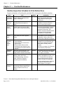
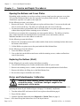
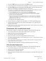
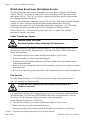
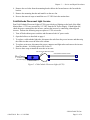
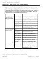
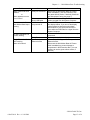
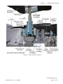
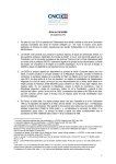
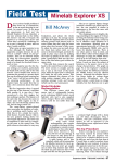
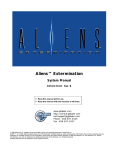
1
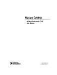
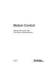
Mini-Motion Base Service & Repair Manual
040-0226-01 Rev. A
¾ Read this manual before use.
¾ Keep this manual with the machine at all times.
www.globalvr.com
http://service.globalvr.com
[email protected]
Phone: 408.597.3435
Fax: 408.597.3437
Nitro Stunt Racing © 2009 Game Seed. GLOBAL VR and the GLOBAL VR logo are registered trademarks of Global VR, Inc. All Rights Reserved. All other
trademarks are the properties of their respective owners.
Table of Contents
Table of Contents
Warnings .........................................................2
Chapter 1 — Introduction ....................................3
General Precautions ...........................................3
Weight Limit ......................................................3
Chapter 2 — Routine Maintenance .....................4
Routine Inspection Schedule for Mini-Motion
Base .............................................................4
Using the Motion Test Menu..............................5
Chapter 3 — Service and Repair Procedures.......6
Opening the Bellows and Cover Plates ..............6
Replacing the Bellows (Skirt) ............................6
Motor and Potentiometer Calibration.................6
Potentiometer (Pot) Assembly Replacement......7
Lifter Assembly Replacement ............................7
Rod End Replacement........................................8
Motor Replacement ............................................8
Electronics Box Replacement............................ 9
Seat Bearing Replacement................................. 9
Motion STOP Button Service ............................ 9
Seat Slide Assembly Replacement..................... 9
Rear (Seat) Speaker or Subwoofer
Replacement................................................ 9
Mini-Motion Base Power Distribution Service10
Power Transformer Service .......................... 10
Fan Service ...................................................... 10
Cold-Cathode Florescent Light Service........... 11
Chapter 4 — Mini-Motion Base
Troubleshooting............................................... 12
Chapter 5 — Diagrams and Schematics............ 14
Technical Support ............................................... 16
List of Figures
Figure 1. Motion Test Menu .................................5
Figure 2. Cold-Cathode Florescent Lights
(CCFL) ......................................................11
Figure 3. Mini Motion Base Simplified Wiring
Diagram .....................................................14
Figure 4. Motor & Lifter Assembly ................... 15
Warnings
To avoid electrical shock, unplug the BOTH cabinet AC Power Cords
before performing installation or service procedures.
If a power cord is damaged, it must be replaced by the equivalent
power cord available from GLOBAL VR or your distributor.
GLOBAL VR® assumes no liability for any damages or injuries incurred
while setting up or servicing the cabinet. Only qualified service
personnel should perform installation or service procedures!
Twisted — Nitro Stunt Racing Mini-Motion Base Service & Repair Manual
Page 2 of 16
040-0226-01 Rev. A 9/16/2009
Chapter 1 — Introduction
Chapter 1 — Introduction
This document contains Maintenance, Service, and Repair information for the Twisted
Mini-Motion Seat Base only. For all other service information refer to the Twisted — Nitro Stunt
Racing Operation & Service Manual, Part Number 040-0224-01.
The Display Cabinet used with the Mini-Motion Base is the same as the 42" Deluxe (nonmotion) configuration except for the additional AC connection and On/Off breaker on the AC
Power Plate.
General Precautions
GLOBAL VR assumes no liability for any damage or injuries incurred while
servicing the cabinet. Only qualified service personnel should perform service
and installation of cabinet hardware.
Do not connect or disconnect any cables or connectors with the power on.
Doing so could potentially damage the game.
To prevent electrostatic discharge (ESD) damage, handle PCBs by the edges only
and use a grounding wrist strap or similar precaution.
Please read the service instructions before working on the cabinet.
The Display Cabinet and Mini-Motion Base have components that produce HIGH
VOLTAGE. Repairs must be performed by authorized personnel only.
Always turn the cabinet OFF and disconnect both AC power cords before
performing any repair work. Wait 5 minutes before replacing any electrical part
or parts on the Motion Base to avoid the risk of shock.
•
Do not tamper with the original wiring configuration, or the positioning of ferrite shields
and clamps. Alteration of game wiring may result in faulty operation.
•
Always return all leg levelers to the extreme up position before moving the game.
•
Always separate the Display Cabinet from the Mini-Motion Base before moving the
game.
Weight Limit
The maximum player weight for the Mini-Motion Seat is 350 lbs. The seat has a fail-safe system
to protect the motor. When the system detects too much current is being drawn by the motor,
indicating a weight overload, the PCB will shut down the motion system. Once this happens,
you can reset the PCB by either pushing in and pulling out the Motion-STOP button, or by power
cycling the Mini-Motion Base with the switch on the back of the display cabinet. A message
will appear onscreen to tell players to push in the Motion STOP Button to restart motion. This
will be followed by the standard Pull Out for Motion message.
040-0226-01 Rev. A 9/16/2009
©2009 Global VR, Inc.
Page 3 of 16
Chapter 2 — Routine Maintenance
Chapter 2 — Routine Maintenance
Routine Inspection Schedule for Mini-Motion Base
Regular maintenance will prolong the operational life of your game and enhance gameplay.
Item
Bellows
around MiniMotion Base
Task
Visually inspect for tears, rips, and
loose or missing retaining screws.
Replace if damaged.
When
Daily
Bellows
Retaining
Screws
Resting
motion
inspection
Visually inspect for loose or missing
retaining screws and replace or
tighten.
With the Motion STOP Button up,
visually inspect the game to make
sure it is not moving in Attract Mode.
Weekly
Motion
function
check
Make sure the game is level during
Attract Mode and motion appears
normal.
Weekly
Lifter
Assembly
check
(bellows
open)
1. Check the entire Lifter Assembly for
loose hardware.
2. Check Rod End connections for
signs of wear.
3. If any of these items are worn
excessively, stop using the game
immediately and contact Technical
Support.
Make sure all bolts are tight on the
Connecting Brackets between the
display cabinet and Mini-Motion Base.
Verify that the cooling fans are
working. Clean all air vents.
If a fan stops working, check the
power connection. Replace a
non-working fan immediately.
Monthly
Make sure the game is sitting flat on
all of the leg levelers, and all of the
casters are locked in the full up
position.
Monthly
Connecting
Brackets
Cooling
Fans
Leg
Levelers
Daily
Weekly
Monthly
Comments
The bellows is important for player
safety and prevents debris from
getting inside the motion system
mechanisms.
Missing screws encourage
vandalism. All screws must be in
place to ensure player safety.
The Mini-Motion Base should not
move during Attract Mode. If it does,
this can severely decrease the life
expectancy of the motor. This
condition is usually caused by a bad
pot. Contact Technical Support
immediately for a replacement.
If the platform is not level during
Attract Mode, the pot is probably out
of calibration. Refer to Motor and
Potentiometer Calibration on page 6.
Continuing to run the game with
damaged or worn components may
cause severe damage to the MiniMotion Base, and may void the
warranty.
See Figure 4 on page 15 for lifter and
motor assembly components.
The powerful jolts may cause the unit
to “travel” after extensive use. Make
sure it stays in its location.
Important: The fan in the open area
under the seat platform runs on +12
VDC. The 230 VAC fan inside the
Electronics Box must be serviced
only by a GLOBAL VR technician.
Failure to maintain proper ventilation
may decrease the performance
and/or lifespan of your game.
Twisted — Nitro Stunt Racing Mini-Motion Base Service & Repair Manual
Page 4 of 16
040-0226-01 Rev. A 9/16/2009
Chapter 2 — Routine Maintenance
Using the Motion Test Menu
1. Open the Operator Menu and use the VIEW and ♪ buttons on the control panel to select
Diagnostics: Motion Test.
2. Press the START button to open the Motion Test menu. This menu lets you cycle the motor
through Up, Down, and Center positions. Center is the neutral position; the platform should be
level in this position.
Figure 1. Motion Test Menu
Note: If the motion STOP button is down you will be prompted to pull it up to activate
motion.
3. Press the LOOK BACK button to exit from the Motion Test menu.
040-0226-01 Rev. A 9/16/2009
©2009 Global VR, Inc.
Page 5 of 16
Chapter 3 — Service and Repair Procedures
Chapter 3 — Service and Repair Procedures
Opening the Bellows and Cover Plates
Depending on the procedure you wish to perform, you may simply need to open one cover plate.
To access the Electronics Box or the Pot, open the cover plate on the left side. To access the
Transformer, open the cover plate on the right side.
Do the following to open a cover plate:
1. Remove the screws. The left and right cover plate each have three (3) screws on the side and
four (4) screws on the top. The front cover plate has four (4) screws on the top.
2. For most procedures you should be able to carefully lift the cover plate up against the bellows
without removing the bellows retaining screws or bracket.
For full access to motion drive components you must open the bellows. The bellows is held in
place with a front and rear retaining bracket, secured with screws and washers, and two
additional machine screws and washers on each side.
Do the following to open the bellows:
1. Remove the 14 retaining screws and washers and the front and rear retaining brackets that secure
the bottom of the bellows.
2. Lift the Bellows to gain access to the parts inside the Mini-Motion Base.
Do the following to close the bellows:
1. Lower the Bellows into place.
2. Line up the holes in the bellows and secure with the retaining screws, washers and brackets
removed previously.
Replacing the Bellows (Skirt)
Do the following if you need to replace the bellows assembly:
1. Turn off both cabinet power switches and disconnect both AC power cords.
2. Remove the retaining screws, washers, and brackets at the top and bottom of the bellows.
3. Remove the bellows by lifting it over the Mini-Motion Seat.
4. Reverse these steps to install the new bellows.
Motor and Potentiometer Calibration
Secure all loose clothing, jewelry, and hair before working
around the motor. Lose items could get caught in the
moving parts of the motor.
Perform the following steps only if the motion platform is not level during Attract Mode, or after
replacing the motor or pot. Refer to Figure 4 on page 15 to identify components.
1. Turn the cabinet OFF and remove the left cover plate as described on page 6.
2. Power ON the cabinet.
3. Open the Operator Menu and select Diagnostics: Motion Test (see page 4).
Twisted — Nitro Stunt Racing Mini-Motion Base Service & Repair Manual
Page 6 of 16
040-0226-01 Rev. A 9/16/2009
Chapter 3 — Service and Repair Procedures
4. Press the START button to move the motor to the DOWN position.
5. Look at the motor and verify that the Lifter mechanism is at the lowest point in its vertical travel.
6. Press the START button to move the motor to the UP position. Look at the motor and verify
that the Lifter mechanism is at the highest point in its vertical travel.
7. If the motor is not stopping at the full up and full down positions, refer to Figure 4 on page 15
and perform the following steps to calibrate the motor potentiometer:
a. Press the START button to move the platform to the CENTER position.
b. Loosen (do not remove) the Pot Alignment Set Screw that attaches the Pot Support
Bracket to the Pot Adjustment Plate.
c. Rotate the Pot Adjustment Plate slightly clockwise or counter-clockwise to adjust the
angle of the lifter bearing. The lifter arm should be vertical, and the clamps should be
perpendicular to the lifter arm.
d. Re-tighten the Pot Alignment Set Screw.
8. Test the calibration by cycling the motor through the UP, CENTER, and DOWN positions.
9. Exit from the Operator Menu and verify that the motion platform is level when the game is
running in Attract Mode.
10. Lift the bellows into place, line up the holes and secure them with the retaining screws, washers
and brackets removed previously.
Potentiometer (Pot) Assembly Replacement
Refer to Figure 4 on page 15 to identify motor components, and perform the following steps:
1. Turn off both cabinet power switches and disconnect both AC power cords.
2. Remove the left cover plate as described on page 6.
3. Disconnect the connector on the pot harness.
4. Remove the bolt that secures the Pot Support Bracket to the Steel Spacer.
5. The Elastic Coupler that attaches to the Pot shaft has four set screws. Loosen the two set screws
that are closest to the pot.
6. Reverse these steps to install the new Pot Assembly. Make sure there is some play in the Pot
Support Bracket. Do not over tighten.
7. Calibrate Motor and Potentiometer Assembly as described in the previous section.
Lifter Assembly Replacement
Refer to Figure 4 on page 15 to identify motor components, and perform the following steps:
1. Turn off both cabinet power switches and disconnect both AC power cords.
2. Move the seat to the fully forward position.
3. Open the bellows as described on page 6.
4. Remove the nut and washer that secures the rod end under the seat platform and rotate the lifter
arm down.
040-0226-01 Rev. A 9/16/2009
©2009 Global VR, Inc.
Page 7 of 16
Chapter 3 — Service and Repair Procedures
5. Loosen the three nuts and bolts that secure the lifter to the blue bearing housings and remove the
lifter.
6. Reverse the removal steps to install the new lifter.
7. Calibrate the Motor and Potentiometer Assembly as described on page 6.
Rod End Replacement
1. Turn off both cabinet power switches and disconnect both AC power cords.
2. Move the seat to the fully forward position
3. Open the bellows as described on page 6.
4. Remove the nut and washer that secures the rod end under the seat platform and rotate the lifter
down.
5. Unscrew the rod end from the lifter arm by using a wrench at the bottom of the rod end
assembly.
6. Screw the new rod end firmly onto the lifter arm.
7. Reassemble the components in the reverse order or disassembly.
Motor Replacement
Refer to Figure 4 on page 15 to identify components, and perform the following steps:
1. Turn off both cabinet power switches and disconnect both AC power cords.
2. Open the bellows as described on page 6.
3. Disconnect the Motor Power Cable from the Electronics Box and snip the cable ties that secure it
to the base.
4. Remove the nut and washer that secures the rod end under the seat platform.
5. Lift the seat and platform forward.
6. Loosen the nut on the clamp to loosen the clamp.
7. Remove the four mounting bolts from the pillow bearings and slide the bearing and lifter
assembly away from the motor.
8. Remove the motor mounting bolts and lift the motor out of the cabinet.
9. Reverse these steps to install the new motor
10. Calibrate the Motor and Potentiometer as described on page 6.
Twisted — Nitro Stunt Racing Mini-Motion Base Service & Repair Manual
Page 8 of 16
040-0226-01 Rev. A 9/16/2009
Chapter 3 — Service and Repair Procedures
Electronics Box Replacement
PREVENT INJURY OR DEATH: Never open the Electronics Box.
The Electronics Box must be serviced by a GLOBAL VR technician.
Components in the Electronics Box are powered by ~230 VAC. Attempts to
improperly service may cause SERIOUS INJURY OR DEATH.
1. Turn off both cabinet power switches and disconnect both AC power cords.
2. Remove the left cover plate as described on page 6.
3. Disconnect the six cables from the Electronics Box:
•
•
•
Main power cable from transformer
Motor power cable
Motion STOP Button cable
•
•
•
Data cable from pot
USB cable from System Computer
DC power harness
Important: Do not pull on the cables to disconnect them; grip and pull the connectors only.
4. Remove the four mounting screws that secure the Electronics Box in place and lift the box out.
5. Reverse these steps to install the new Electronics Box.
Important: Make sure all cables are firmly and properly connected.
Seat Bearing Replacement
Do the following to replace the bearings at the front of the seat platform:
1. Turn off both cabinet power switches and disconnect both AC power cords.
2. Open the bellows as described on page 6.
3. Loosen the set screw that secures the bearing to the pivot stud.
4. Remove the two bolts with washers that secure the bearing in place and slide the bearing off the
pivot stud.
5. Reverse these steps to install the new seat bearing.
Motion STOP Button Service
The Motion STOP Button is mounted to the Display Cabinet. It contains two switches. One
switch is connected to the GVRI/O Mini PCB in the Display Cabinet, which puts a message
onscreen when the button is down. The other switch is connected to the Electronics Box in the
Mini-Motion Base.
Seat Slide Assembly Replacement
Please refer to the Twisted Operation and Service Manual for this procedure.
Rear (Seat) Speaker or Subwoofer Replacement
Please refer to the Twisted Operation and Service Manual for this procedure.
040-0226-01 Rev. A 9/16/2009
©2009 Global VR, Inc.
Page 9 of 16
Chapter 3 — Service and Repair Procedures
Mini-Motion Base Power Distribution Service
The Mini Motion Base gets its power through the AC Power Plate on the back of the Display
Cabinet. The 115 VAC power is connected to a Power Transformer in the Mini-Motion base
that outputs 230 VAC. The 230 VAC power is connected to the Electronics Box that contains
the components that drive the motor.
Primary power distribution components consist of the AC Power Plate on the back of the Display
Cabinet, AC Power cord between the Power Plate and Mini-Motion Base, the Power
Transformer that outputs 230 VAC for the Mini-Motion Base components. +12 VDC for the
CCFL lights and fan are provided by the DC Power Supply in the Display Cabinet.
Refer to the Twisted — Nitro Stunt Racing Operation & Service Manual for a detailed
description of the AC Power Plate.
Power Transformer Service
DANGER HIGH VOLTAGE!
Disconnect power before servicing the transformer.
The power transformer in the motion base transforms 115 VAC input voltage to 230 VAC to
power the Servo Driver in the Electronics Box, which drives the motor. Do the following to
replace the transformer:
1. Turn off both cabinet power switches and disconnect both AC power cords.
2. Remove the right cover plate as described on page 6.
3. Disconnect the wires from the transformer and connect them to the same terminals on the
replacement transformer.
4. Remove the four mounting bolts that secure the transformer in place and use them to secure the
new transformer.
5. Be sure to re-connect the green ground wire on the output harness to one of the mounting bolts.
Fan Service
The Mini-Motion Base has a +12 VDC fan in the open area under the seat platform, and a
220 VAC fan inside the Electronics Box.
The 220 VAC fan in the Electronics Box should be serviced ONLY by a
GLOBAL VR technician.
It is important for the fans to be working properly to prevent overheating the components in the
Mini-Motion base. Keep the fans and all ventilation holes clear of dust and debris so air can
flow freely. If either fan stops working it should be replaced immediately.
Do the following to replace the 12 VDC fan:
1. Turn off both cabinet power switches and disconnect both AC power cords.
2. Remove the left cover plate as described on page 6.
3. Disconnect the fan power connector and snip any cable ties securing the wires in place.
Twisted — Nitro Stunt Racing Mini-Motion Base Service & Repair Manual
Page 10 of 16
040-0226-01 Rev. A 9/16/2009
Chapter 3 — Service and Repair Procedures
4. Remove the two bolts from the mounting bracket below the fan and remove the fan with the
bracket.
5. Remove the mounting bracket and install it on the new fan.
6. Reverse the removal steps to install the new 12 VDC fan in the motion base.
Cold-Cathode Florescent Light Service
Dual Cold-Cathode Florescent Lights (CCFLs) provide the red lighting on the back of the MiniMotion Base. CCFLs are powered by +12 VDC from the DC Power Supply. If both lights fail,
check the power connection to the inverter, and test the inverter by connecting a known good
inverter. Perform the following steps to replace a CCFL or inverter:
1. Turn off both cabinet power switches and disconnect both AC power cords.
2. Open the bellows as described on page 6.
3. To replace a cold-cathode light tube, disconnect the tube from the power inverter and then snip
the cable ties that secure the tube to the cabinet.
4. To replace an inverter, disconnect the power connector and light tubes and remove the inverter
from the cabinet. It is held in place with Velcro™.
5. Reverse these steps to install the new tube or inverter.
2-Pin Connector Attached to Tube
Cold-Cathode Florescent Tubes
+12 VDC In from
DC Power Supply
Power Inverter
Figure 2. Cold-Cathode Florescent Lights (CCFL)
040-0226-01 Rev. A 9/16/2009
©2009 Global VR, Inc.
Page 11 of 16
Chapter 4 — Mini-Motion Base Troubleshooting
Chapter 4 — Mini-Motion Base Troubleshooting
Note: If the Mini-Motion Base is powered OFF, but the Display Cabinet is powered ON, the
CCFL lighting and ventilation fan in the Mini-Motion Base will work, as they are powered by
the DC Power Supply in the Display Cabinet.
If the Mini-Motion Base is powered ON, but the Display Cabinet is powered OFF, the base will
move uncontrollably as the PCB waits for a signal from the System Computer. The 12 VDC
ventilation fan and CCFL lighting in the motion base will be off.
Problem
Motion Platform is not
level during Attract Mode
There is no 230 VAC
power to the Mini-Motion
Base
Cause
Motor and Pot are not
calibrated
Base is not plugged
in
Tripped Breaker on
AC Power Plate
Blown Fuse on
Electronics Box
Tripped Breaker for
AC Wall Outlet
No voltage output
from the Transformer
Motor is not responding
There IS 230 VAC power
to the Electronics Box
Mini-Motion Base moves
during Attract Mode
Motion STOP Button
is down
Motion STOP Button
cable faulty or not
connected properly
Motion STOP Button
is faulty
Loose or faulty USB
cable
Loose or faulty motor
cable
Faulty component in
Electronics Box
Faulty Motor
Faulty Pot
Possible Solution
Test the motor as described on page 4; if
needed, calibrate as described on page 6.
Check the AC power cords from the wall
outlets to the Display Cabinet, and the Display
Cabinet to the Mini-Motion Base.
Check the Breaker on the power plate at the
rear of the Display Cabinet.
Check the fuse on the Electronics Box.
Replace with 7 Amp fuse if blown.
Check the Breaker Switch for the AC Wall
Outlet.
Check the Transformer input and output
voltage. Input voltage should be ~115 VAC.
Output voltage should be ~230 VAC.
Pull up the Motion STOP Button.
Check the cable connections to the Motion
STOP Button and Electronics Box.
Check continuity across the Motion STOP
Button.
Check the USB cable between the computer
and Electronics Box
Check cable from Electronics Box to Motor.
Contact Technical Support for assistance.
Check to see if the Motor Shaft will rotate by
hand (with no power to the Motor). If it will not,
your Motor is faulty. If it will rotate, check the
Motor Cable.
Disconnect the Mini-Motion Base AC Power
Cord Immediately. (You can continue to use
the game without motion, if desired.) Replace
the pot as described on page 7.
Twisted — Nitro Stunt Racing Mini-Motion Base Service & Repair Manual
Page 12 of 16
040-0226-01 Rev. A 9/16/2009
Chapter 4 — Mini-Motion Base Troubleshooting
Problem
Motor cannot find home
position
or
Motor appears to move
out of control
Game is turned off but
Mini-Motion Base keeps
moving
12 VDC Ventilation Fan
is NOT working
Fan in Electronics Box is
NOT working
Motor is functional
040-0226-01 Rev. A 9/16/2009
Cause
Faulty Pot Loose Pot
Disconnected or
faulty USB Cable
Mini-Motion Base is
not powered off
Loose or faulty wiring
Faulty Fan
Problem is inside
Electronics Box
Possible Solution
Disconnect the Mini-Motion Base AC Power
Cord Immediately. (You can continue to use
the game without motion, if desired.) Check the
pot and replace if faulty (see page 7).
The motor will keep moving if it does not
receive a signal from the System Computer.
Turn off BOTH power switches on the back of
the display cabinet. If you turn off the display
cabinet power but leave the motion base
power switch on, the game will continue to
move while the PCB waits for a signal from the
System Computer.
Make sure the Fan Power Harness is securely
connected.
Replace a faulty fan immediately.
Contact Technical Support. Do not open the
Electronics Box.
Disconnect the Mini-Motion Base AC Power
Cord Immediately to prevent damage to
components in the Electronics Box. (You can
continue to use the game without motion, if
desired.)
©2009 Global VR, Inc.
Page 13 of 16
Chapter 5 — Diagrams and Schematics
Chapter 5 — Diagrams and Schematics
Display Cabinet
To
AC Power Plate
115-0222-01
To GVRI/O
Mini PCB
To
Motion STOP Button
To
System Computer
To
DC Power Supply
PN: 115-0221-01
USB Extension Cable
USB-EXT-6
CBL-0804-X
115-0151-01
To
Audio Amp
CBL-0800-X
115-0205-01
115 VAC In
+12/-12 VDC Power In
CBL-0803-X
CBL-0804-X
Transformer
230 VAC Out
USB Cable
USB-AB06MM
To
Seat Speakers
& Subwoofer
CBL-0801-X
Electronics Box
(Do Not Open)
12 VDC
Fan
CBL-0805-X
CCFL
Inverter
Motor Drive Pulses Out
CBL-0806-X
Motor
Pot
CBL-0802-X
Figure 3. Mini Motion Base Simplified Wiring Diagram
Note: In countries with 220-230 VAC line voltage, the Electronics Box will be powered directly
without requiring the power transformer.
Twisted — Nitro Stunt Racing Mini-Motion Base Service & Repair Manual
Page 14 of 16
040-0226-01 Rev. A 9/16/2009
Chapter 5 — Diagrams and Schematics
Figure 4. Motor & Lifter Assembly
040-0226-01 Rev. A 9/16/2009
©2009 Global VR, Inc.
Page 15 of 16
Technical Support
Service & Parts
Hours: 7:00AM–5:00PM Pacific Time, Monday–Friday
Phone: 408.597.3435
Fax: 408.597.3437
E-mail: [email protected]
Website: http://service.globalvr.com
Extended Service Hours:
Monday–Friday 5pm—Midnight
Saturday & Sunday 7:00am—Midnight Pacific Time
Free telephone, e-mail, and online support are provided for systems during the warranty period.
GLOBAL VR® Technical Support can help you troubleshoot problems and diagnose defective
parts. We can also answer questions about the operation of your game.
When you contact Technical Support, please provide the information listed below to assist the
Technical Support representative in solving your problem quickly. For your convenience, space
is provided to write important numbers.
•
Cabinet Serial Number:
•
Game Version (from Operator Menu):
•
OS Version (from Operator Menu):
•
Dongle Version (from Operator Menu):
•
IO Board Version (From Operator Menu):
•
Your mailing address and telephone number.
•
A summary of the question or a detailed description of the problem with your cabinet.
The additional information listed below, as applicable, may assist Technical Support in solving
your problem quickly.
•
Specific error message
•
Date of latest install or upgrade
•
Any changes made to the system
•
For game-play issues, the game mode and
number of players
To comment on this manual, please e-mail: [email protected]