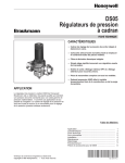
1
INsTRUCTION
2-1 Wiring installation instructions
Thank you for purchasing KOSO RX2NR, before operating the unit, please read the instruction thoroughly and retain it for the future reference.
Green / Ground
BATTERY
1604
6LR619V
Notice
Black / DC 9V
Power supply: battery (9V-1604, 6LR61.)
For installation, please follow the steps described in manual. Any damage caused by wrong installation shall be imputed to the users.
Don't break or modify the wire terminal. To avoid the short circuit, please don't pull the wire when installing.
Do not disassemble or change any parts excluding the manual description.
The interior examination or maintenance should be executed by our professionals.
Brown/ RPM wire please connect
it to the suitable position according
to the models.
MARK MEANING:
You could get the installation details from the information behind the mark.
Some processes must be followed to avoid the affection caused by wrong installation.
WARNING! Some processes must be followed to avoid damages to yourself or the public.
1-1
1
5
9
Temp sensor wire
(Accessory 5)
Meter mai nwire set (Accessory 2)
Press the
Button one time
Meter (Accessory 1)
Press the
Button 3
Seconds
A3
Battery case
(Accessory 7)
Please install the temp sensor (Accessory 6)
to the position you want to measure.
B
A2
A1
B1
A
RPM wire set-Type B
(Accessory 4)
RPM wire set-Type A
(Accessory 3)
Ignition coil positive
Accessory
2
Meter X 1
Temp sensor wire X 1
Bind X 1
13 M5 gasket X 3
6
3
Main wiring X 1
PT 1/8 water temp
sensor X 1
7
RPM wire (Type A) X 1
Battery case X 1
4
8
Coil
RPM wire (Type B) X 1
Foam X 1
EMS
CDI
1.
2.
3.
4.
5.
D
RPM wiring reference:
YAMAHA Yellow / Black
Yellow / Green
HONDA
Yellow / Blue
SUZUKI
Light Blue
KAWASAKI
Gray
/ Violet
APRILIA
Black
BMW
BENNELLI Gray / Violet
BUELL
CAGIVA
DUCATI
H-D
MV
TRIUMPH
Pink
Gray / Green
Gray / Green
Pink
Gray / Yellow
Red
Tachometer
Flywheel
Ignition
pulse
C
RPM wire set-Type A
(Accessory 3)
pick up
Spark plug wire
Spark plug
Spark cap
E
The color listed above may differ depending
on the model.
10 3 mm spanner X 1
11 Meter bracket X 1
12 M4 screw X 3
14 M6 X 35L screw X 2
15 M8 X 30L screw X 2
16 M6 screw X 2
The temperature will disappear if you don't install & connect the temperature sensor with the meter.
The RPM wire installation
A. Please wrap the RPM wire at least 5 times around the spark plug.
A1. Please use tape to fix the RPM (Type A) wire onto the spark plug wire.
A2. Please use tape to fix the RPM wire (Type A) on the spark plug cap.
A3. Please use tape to fix the RPM wire (Type A) on the coil positive pole wire. For some models with the coil negative wire, please tape
the RPM wire (Type A) on the negative wire to get the RPM signal. (For example, the YAMAHA V-max 1200)
B. Please connect the RPM wire (type B) to connect to the ignition coil positive pole.
B1. Please wrap the RPM wire (type B) on the spark plug wire by connecting the male and female connector.
C. Please connect the RPM wire (Type A) to the pick up.
D. Please parallel the RPM wire (Type A) with the original tachometer signal wire (This method is available only when the original
speedometer comes with a tachometer on it. You could get the RPM wire information from the service manual of your bikes.)
E. For the models comes with the new ignition coil, please wrap the RPM wire (Type A) at least 5 times around the spark plug as the
above drawing.
For multi-ignition models, we will suggest you to get the signal on the first ignition.
The best signal source will be in order as D>C>B>A, we will suggest you to check different ways if you have problems to get the
RPM signal.
2-2 Installation instructions
When installing, please follow the process
1.
2.
1.
19 M8 gasket X 2
18 M6 gasket X 2
17 M8 screw X 2
2.
7.
3.
6.
7.
4.
Please contact the local distributor if the items you open are not the same, with the above-listed one.
1-2
1 Temp sensor wire (2 M)
8.
Option accessory
4.
2
Oil temp sensor adapter
M12 X P1.5
M14 X P1.25
M14 X P1.5
M16 X P1.5
M18 X P1.5
M20 X P1.0
M20 X P1.5
5
Cylinder head
temp sensor
9.
6
X
X
X
X
X
X
X
15L
15L
15L
15L
15L
15L
15L
3
Water temp
sensor adapter
M14
M16.M18
M22.M26 mm
4
Temp sensor
5.
7.
1.M6 or M8 screw X 2 (Accessory 14.15)
2.M6 or M8 aluminum screw washer X 2 (Accessory 16.17)
3.Bracket (Accessory 11)
4.M6 or M8 bushing X 2 (Accessory 18.19)
5.Handle bar bracket
You could also install it (Meter bracket) on the original
meter bracket.
6.M5 screw X 3 (Accessory 12)
7.M5 washer X 3 (Accessory 13)
8.Meter (Accessory 1)
9.Meter bracket micro-adjustment screw
You could choose the angle first and then use the
screw to fix the angle.
The handle bar bracket screw and screw hole will
differ depending on different model. We suggest you
to use the additional assembly (Item 1.2.4) to fit it.
M10 X P1.0
M12 X P1.5
M14 X P1.25
M14 X P1.5
M16 X P1.5 / M18 X P1.5
Meter bracket
(For handle bar)
M10.
M14 mm
Some of the option accessories may not sell. For the details, please contact the local distributor.
wh015ba005
2-3 The instruction of battery box fix to the bike frame 2-4 The instruction of battery box fix to the bike case
When installing,
please follow the process
When installing,
please follow the process
Press the Select button to enter the signal
input setting screen.
EX. Now the piston setting is changed from
1 P (Piston) to 4 P (Pistons).
Press the Adjust button to change the setting
digit.
Setting range: -500~-5,000 RPM.
Setting unit: 100 RPM.
EX. To change the setting to Lo.
(The negative impulse)
Press the Adjust button to choose the input
signal you want to set.
EX. Now the setting is Hi (The positive impulse)
The input signal setting range is
between hight (The positive signal) &
low (The negative signal)
Press the Select button to enter the over heat
warning light setting screen.
EX. Now the pre-shift light setting is changed
from 1,000 RPM to 1,500 RPM.
4.
1.
1. Bike Frame.
2. Please put the foam on the top of
the battery box.
3. Battery box put the battery box on
sponge.
4. Belt tie the battery box to the bike
frame via belt.
1. Bike case drill two hole (3 X 10 mm)
on the bike case.
2. Please put the foam on the top of
the battery box.
3. Battery box put the battery box on
sponge.
4. Belt tie the battery box to the bike
frame via belt.
1.
4.
2.
2.
3.
3.
Now the input signal setting is flashing!
If the tachometer can't detect the
signal (No RPM is displayed on the
screen), you could choose another
setting, and check it again.
3-1 Overview
Press the Select button to enter the shift light
setting screen.
EX. Now the input signal is changed from hight
to low.
The RPM shift light
Setting range:5,000~16,000 RPM.
Setting unit:100 RPM.
Pre-shift light
Setting range:
-500~-5,000 RPM.
Setting unit: 100 RPM.
Tachometer (16,000 RPM)
Display range: 0~16,000 RPM.
Over heat warning light o
o
C (140~302 F).
Setting range:o 60~150
o
Setting unit: 1 C (1 F).
Pre-shift light
(Yellow light)
Adjust button
The digit you could set is flashing now.
The Digital tachometer
Display range:0~16,000 RPM.
Display range:100 RPM.
P.S.
3-2 Function, setting instruction
Needle tachometer
Digital tachometer
Display internal
Shift light
Pre-Shift light
Stroke / piston setting
EX. The shift light set on 9,500 RPM.
P.S.
Press the Select button to move to the digit
The temperature light
you want to set.
EX. Now the RPM shift light setting is 9,000 RPM. will light on when the
temperature reached your
setting.
Shift light
(Red light)
Thermometer
o
o
Display range:o 0~150
C (32~302 F).
o
Display unit: 1 C (1 F).
Select button
Display range: 0~16,000 RPM
Display range: 0~16,000 RPM
Display unit: 100 RPM
<0.5 second
Setting range: 5,000~16,000 RPM
Setting unit: 100 RPM
Setting range: -500~-5,000 RPM
Setting unit: 100 RPM
2 Stroke: 1, 2, 3, 4 pistons
4 Stroke: 1, 2, 3, 4, 5, 6, 8, 10, 12 pistons
Thermometer
o
o
Display range: 0~150 C 0~302 F
o
o
Display unit: 0.1 C 0.1 F
Display internal
<0.5 second
o
o
Over heat warning light
Setting range: 60~150 C 140~302 F
o
o
Setting unit: 1 C 1 F
Battery type
9V-1604, 6LR61
Effective temperature range -10~+60oC
Meter standard
JIS D 0203 S2
Meter size
135.7 X 100.7 X 52 mm
Around 240 g
Meter weight
Pre-shift light (-1,500 RPM)
Press the Adjust button to change the setting
digit.
Setting range: 60~150oC (140~302oF)
Setting unit: 1oC (1oF).
The digit you could set is flashing now.
The setting unit will change together with the
temperature unit setting.
Shift light (9,500 RPM)
If you set the RPM shift light at 9,500 RPM, the yellow light (Pre-shift
light) will light on at 8,000 RPM.
And the red light (Shift light) will light on when it reaches 9,500 RPM.
Press the Adjust button to change the setting
digit.
Setting range: 5,000~16,000 RPM
Setting unit:100 RPM
Design and specification are subject to change without notice!
Press the Select button to enter the pre-shift
light setting screen.
EX. Now the shift light setting is changed from
9,000 RPM to 9,500 RPM.
4-1 Adjust button function instruction
Press Adjust button one timeo to switch
the
o
temperature unit between C and F.
Press the Select button to back the main
screen.
EX. Now
the setting is changed from 100oC
to 105oC.
Main screen.
EX. The pre-shift RPM set on 8,000 RPM.
(It means that the pre-shift light will light on
1,500 RPM before the shift light.)
Press the Select button to move to the digit
you want to set.
EX. Now the RPM pre-shift light setting is -1,000
RPM.
4-2 Cycle / Piston / Input signal setting
In the main screen, press down the Select &
Adjust button together for 3 seconds to enter
the setting screen.
EX. The over heat warning set on 105oC.
Press the Select button to move to the digit
you want to set.
EX. Now the over heat warning setting is
100.0oC.
Press the Select button to enter the piston
setting screen.
EX. Now the setting is changed from 2 cycle
to 4 cycle.
5 Trouble shooting
The following situation do not indicate malfunction of the meter. Please check the following before taking it in for repair.
EX. To change the setting to 4 stroke.
Press the Adjust button to select the stroke.
EX. Now the setting is 2C (2 Stroke).
You could set the stroke as 2 stroke or 4
stroke.
The digit you could set is flashing now.
CAUTION!
Make sure the correct strokes and pistons before setting.
Make sure the input is correct, or the RPM output will be
incorrect.
We define the engine with the ignition system ignites every
360 degree as 2-stroke and the engine with the ignition
system ignites every 720 degree as 4-stroke.
Some 4-stroke bikes with one single piston are igniting every
360 degree once, so the setting should be the same as the
bike with 2-stroke and one piston engine.
EX. To change the setting to 4piston.
Press the Adjust button to select the piston
digit.
EX. Now the setting is 1P (1 piston).
2 Cycle: 1,2,3,4 pistons
4 Cycle: 1,2,3,4,5,6,8,10,12 pistons
The digit you could set is flashing now.
Trouble
The meter doesn't work
when the power is on.
Trouble
Check item
The power doesn't supply to the meter.
Please make sure the wiring is
connected. The wiring and fuse are not
broken.
The battery is broken or the battery is too
old to supply enough power (DC 9 V) to Temp does not appear
make the meter work.
or appear incorrectly.
The meter shows wrong Please check the voltage of your
information.
battery, and make sure the voltage is
over DC 9 V.
Tachometer does not
Please check the RPM sensor wiring is
appear or appear
connected correctly.
incorrectly.
Check item
Please check the spark plug is R type
or not. If not, please replace the spark
plug with the R type spark plug.
Please check your setting.
Please refer to the manual 4-2.
Please check the sensor.
Does the wiring break or falling off ?
If still can't solve the problems according to the steps above, please contact with distributors or us.
wh015ba005