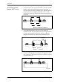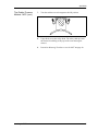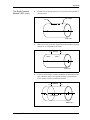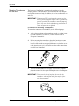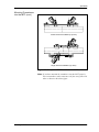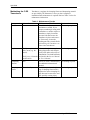
1
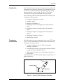
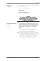
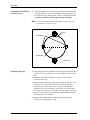
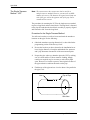
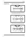
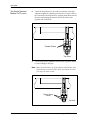
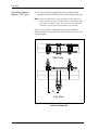
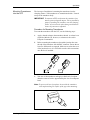
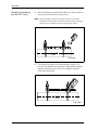
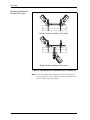
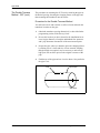
C-RS Ultrasonic
Flow Transducer
Installation Guide
April 2004
Process Control Instruments
C-RS Ultrasonic Flow Transducer
Installation Guide
916-077A
April 2004
Table of Contents
Introduction. . . . . . . . . . . . . . . . . . . . . . . . . . . . . . . . . . . . . . . . . . . . . . . . . . . . . . . . . . . . . . . . 1
Transducer Construction . . . . . . . . . . . . . . . . . . . . . . . . . . . . . . . . . . . . . . . . . . . . . . . . . . . . . . 1
Couplants . . . . . . . . . . . . . . . . . . . . . . . . . . . . . . . . . . . . . . . . . . . . . . . . . . . . . . . . . . . . . . . . . 2
Preparing for Installation . . . . . . . . . . . . . . . . . . . . . . . . . . . . . . . . . . . . . . . . . . . . . . . . . . . . . 3
Choosing an Installation Location . . . . . . . . . . . . . . . . . . . . . . . . . . . . . . . . . . . . . . . . . . . 3
Preparing the Pipe . . . . . . . . . . . . . . . . . . . . . . . . . . . . . . . . . . . . . . . . . . . . . . . . . . . . . . . . 4
Obtaining the Transducer Spacing . . . . . . . . . . . . . . . . . . . . . . . . . . . . . . . . . . . . . . . . . . . 5
Determining the Number of Traverses . . . . . . . . . . . . . . . . . . . . . . . . . . . . . . . . . . . . . . . . 5
Installing the Universal Clamping Fixture and Transducers - UCF . . . . . . . . . . . . . . . . . . . . . 7
Verify Fixture Length . . . . . . . . . . . . . . . . . . . . . . . . . . . . . . . . . . . . . . . . . . . . . . . . . . . . . 7
Identifying the UCF Components. . . . . . . . . . . . . . . . . . . . . . . . . . . . . . . . . . . . . . . . . . . . 7
The Double-Traverse Method -UCF. . . . . . . . . . . . . . . . . . . . . . . . . . . . . . . . . . . . . . . . . . 9
The Single-Traverse Method - UCF . . . . . . . . . . . . . . . . . . . . . . . . . . . . . . . . . . . . . . . . . 12
Mounting Transducers into the UCF . . . . . . . . . . . . . . . . . . . . . . . . . . . . . . . . . . . . . . . . 17
Installing the General Clamping Fixture and Transducers - GCF . . . . . . . . . . . . . . . . . . . . . 21
The Double-Traverse Method - GCF . . . . . . . . . . . . . . . . . . . . . . . . . . . . . . . . . . . . . . . . 21
The Single-Traverse Method - GCF . . . . . . . . . . . . . . . . . . . . . . . . . . . . . . . . . . . . . . . . . 25
Mounting Transducers into the GCF . . . . . . . . . . . . . . . . . . . . . . . . . . . . . . . . . . . . . . . . 29
Installing the Magnetic Clamping Fixture and Transducers - MCF . . . . . . . . . . . . . . . . . . . . 32
Identifying the MCF Components . . . . . . . . . . . . . . . . . . . . . . . . . . . . . . . . . . . . . . . . . . 32
The Double-Traverse Method - MCF . . . . . . . . . . . . . . . . . . . . . . . . . . . . . . . . . . . . . . . . 33
The Single-Traverse Method - MCF . . . . . . . . . . . . . . . . . . . . . . . . . . . . . . . . . . . . . . . . 36
Mounting Transducers into the MCF . . . . . . . . . . . . . . . . . . . . . . . . . . . . . . . . . . . . . . . . 40
Maintaining the C-RS Transducers. . . . . . . . . . . . . . . . . . . . . . . . . . . . . . . . . . . . . . . . . . . . . 44
Specifications . . . . . . . . . . . . . . . . . . . . . . . . . . . . . . . . . . . . . . . . . . . . . . . . . . . . . . . . . . . . . 45
iii
April 2004
Warranty
Each instrument manufactured by GE Panametrics is warranted to be
free from defects in material and workmanship. Liability under this
warranty is limited to restoring the instrument to normal operation or
replacing the instrument, at the sole discretion of GE Panametrics. Fuses
and batteries are specifically excluded from any liability. This warranty
is effective from the date of delivery to the original purchaser. If GE
Panametrics determines that the equipment was defective, the warranty
period is:
•
one year for general electronic failures of the instrument
•
one year for mechanical failures of the sensor
If GE Panametrics determines that the equipment was damaged by
misuse, improper installation, the use of unauthorized replacement parts,
or operating conditions outside the guidelines specified by GE
Panametrics, the repairs are not covered under this warranty.
The warranties set forth herein are exclusive and are in lieu of
all other warranties whether statutory, express or implied
(including warranties or merchantability and fitness for a
particular purpose, and warranties arising from course of
dealing or usage or trade).
Return Policy
If a GE Panametrics instrument malfunctions within the warranty period,
the following procedure must be completed:
1. Notify GE Panametrics, giving full details of the problem, and
provide the model number and serial number of the instrument. If the
nature of the problem indicates the need for factory service, GE
Panametrics will issue a RETURN AUTHORIZATION NUMBER
(RAN), and shipping instructions for the return of the instrument to a
service center will be provided.
2. If GE Panametrics instructs you to send your instrument to a service
center, it must be shipped prepaid to the authorized repair station
indicated in the shipping instructions.
3. Upon receipt, GE Panametrics will evaluate the instrument to
determine the cause of the malfunction.
Then, one of the following courses of action will then be taken:
iv
•
If the damage is covered under the terms of the warranty, the
instrument will be repaired at no cost to the owner and returned.
•
If GE Panametrics determines that the damage is not covered under
the terms of the warranty, or if the warranty has expired, an estimate
for the cost of the repairs at standard rates will be provided. Upon
receipt of the owner’s approval to proceed, the instrument will be
repaired and returned.
April 2004
Introduction
The C-RS ultrasonic flow transducer is used exclusively with the GE
Panametrics line of ultrasonic flowmeters. These transducers measure
the flow rate of sonically-conductive liquids through pipes having
diameters between 2 in. (5 cm) and over 300 in. (7.6 m). Such
measurements are typically independent of the pipe material.
This document provides the following instructions on installing and
maintaining C-RS transducers:
Transducer
Construction
•
•
•
•
Transducer Construction - see below
•
Installing the General Clamping Fixture and Transducers page 21
•
Installing the Magnetic Clamping Fixture and Transducers page 32
•
•
Maintaining Transducers - page 44
Couplants - page 2
Preparing for Installation - 3
Installing the Universal Clamping Fixture and Transducers page 7
Specifications - page 45
The C-RS operates in process temperatures from -40 to 302oF (-40 to
150oC)*. Each C-RS transducer assembly consists of the following
components (see Figure 1 below):
•
a stainless steel adapter with 3/4” NPT male thread for
attaching a junction box
•
a transducer that consists of a peizoelectric element mounted on
a wedge and wired to the BNC connector
•
a BNC style connector for use in connecting the transducer to
the flowmeter.
*This temperature is for ATEX certified designs. Consult factory for
higher temperatures.
BNC Connector
Transducer Body
Adapter
Figure 1: General C-RS Transducer Assembly
Installing C-RS Transducers
1
April 2004
Couplants
GE Panametrics supplies an ultrasonic couplant for your C-RS
installation. The purpose of the couplant is to provide reliable
transmission of ultrasound between two adjacent solid surfaces.
Generally speaking, couplants perform this task by excluding air from
between the adjacent surfaces. Accordingly, the C-RS transducers
should be pressed tightly against the pipe, using hand pressure on the
set screw to squeeze the couplant to as thin a film as practical for the
given pipe surface.
The most commonly used couplants in ultrasonic testing are
ordinarily satisfactory for any short-term clamp-on flowmeter
application. These couplants include, in general order of preference:
gels, grease, propylene glycol, oil, glycerine, and water. Long-term
couplants include grease, epoxy adhesive, and solid rubber-like sheet
couplant.
GE Panametrics provides couplants for both permanent and
temporary use as well as for high- and low-temperature applications.
For long-term installations, make sure the couplant does not dry or
run out.
Standard couplants supplied from GE Panametrics are listed in
Table 1 below.
Table 1: Couplants
PART
NO.
TYPE
CPL-1
Standard
-40 to
(-40 to +65oC)
Semi-Permanent
CPL-2
High/Low
Temperature
-256 to 500oF
(-160 to +260oC)
Semi-Permanent
CPL-3
For Portable
-4 to 140oF
(-20 to +60oC)
Temporary
CPL-4
Special
As Required
*Difficult
Applications
CPL-7
Epoxy
14 to 122oF
(-10 to +50oC)
Permanent
CPL-8
Solid Sheet
-40 to 446oF
(-40 to +230oC)
Permanent
TEMP. RANGE
149oF
USE
* Installations involving hotter or colder temperatures than listed
above, may require special couplants. Consult GE Panametrics for
these applications.
2
Installing C-RS Transducers
April 2004
Preparing for
Installation
Before the clamping fixture and transducers can be properly installed,
you must do the following:
•
Choose an Installation Location
•
Prepare the Pipe
•
Obtain the Transducer Spacing
•
Determine the Number of Traverses
Caution!
A flowmeter’s accuracy and performance
depends on the location, spacing, and alignment
of the transducers. The transducer spacing is
unique to your installation.
Choosing an Installation
Location
1.
Locate the transducer measurement point at least 3 ft (1 m) or
more from any butt welds or flanges, ideally in the center of a
20 ft (6 m) length of straight run of pipe. Keep appropriate
clearance on either side of the pipe for easy transducer
installation:
•
6 in. (15 cm) if you are not using a junction box, or
•
9 in. (22.5 cm) if you are using a junction box.
Note: To guarantee the specified accuracy of the flowmeter there is
no substitute for a straight run pipe and fully-developed flow
profile. However, if straight run is not available, the
transducer location should be in a position such that the
acoustic signal travels through the full distribution of the
under-developed flow profile for best repeatability.
Installing C-RS Transducers
3
April 2004
Choosing an Installation
Location (cont.)
2.
Place the transducers as close as possible to the horizontal plane.
(see figure below). Locate the transducers on opposite sides of
the pipe 180o apart, ideally at the 3 and 9 o’clock positions. Do
not place transducers on the top or bottom of the pipe.
Note: For best profile identification in limited straight run, place
transducers at 1 and 7 o’clock.
Pipe
Transducer
Signal Path
End View
Preparing the Pipe
1. Prepare the pipe for the transducers by clearing rust and paint from
an area 2 in. (5 cm) wide by 4 in. (10 cm) long on one side of the
pipe.
2. Polish the cleared area, taking care to preserve the original
curvature of the pipe.
3. With an ultrasonic thickness gage, measure the pipe thickness at a
minimum of six spots on the cleared area. Take at least three
measurements at each spot to ensure accuracy. The thickness
should not vary by more than 5% at each spot. If you encounter
more than a 5% variation at each spot, move to another section of
the pipe. Verify that the wall thickness at both transducer locations
has less than the 5% variation.
4. Measure the outside diameter (OD) of the pipe using a tape
measure or the supplied pipe wrap.
4
Installing C-RS Transducers
April 2004
Obtaining the
Transducer Spacing
Before installing the clamping fixture, you must obtain the transducer
spacing from the flowmeter. You will need to know the transducer
spacing later in this procedure.
To obtain the spacing, you must enter the measured OD and the pipe
wall thickness into the flowmeter’s user program (Pipe Parameters) to
determine the transducer spacing. Refer to your User’s Manual or
Startup Guide for more details.
Determining the Number
of Traverses
The next step in installation is determine the number of traverses. The
transducers can be mounted using one of two methods (see Figure 2
on the next page):
•
Double-traverse method (“V” method) - transducers are mounted
on the same side of the pipe and the ultrasonic signal is bounced
from one transducer to the other, off the opposite pipe wall.
•
Single-traverse method (“Z” method) - transducers are mounted
diagonally across from each other. The ultrasonic signal is
transmitted directly from one transducer to the other, across the
pipe.
If the pipe diameter is 4 to 20 in., you should always try the doubletraverse method first since it easier to install and yields greater
accuracy. Otherwise, the single-traverse method is best for pipes with
the following:
•
diameters 20 in. or greater
•
poor inside surface conditions
•
highly attenuating fluid
Note: You may want to try both configurations to see which yields
more accurate results.
Proceed to one of the following sections to properly install your
fixture and transducers.
Installing C-RS Transducers
•
Installing the Universal clamping fixture and transducers page 7.
•
Installing the General clamping fixture (permanent installation)
and transducers - page 21.
•
Installing the Magnetic clamping fixture and transducers page 32.
5
April 2004
Determining the Number
of Traverses (cont.)
Double Traverse (“V” Method)
Transducers
Ultrasonic Signal Path
TOP VIEW
Single Traverse (“Z” Method)
Transducer
Transducer
TOP VIEW
Figure 2: Double- and Single-Traverse Installations
6
Installing C-RS Transducers
April 2004
Installing the Universal
Clamping Fixture and
Transducers - UCF
The Universal Clamping Fixture (UCF) acts as a spacing device and a
transducer holder. The UCF is available in two lengths and consists of
a number of components. Before you begin installation, you should
verify your fixture is the correct length and familiarize yourself with
the fixture components.
IMPORTANT: To maintain ATEX certification the transducer face
must be protected against impact. This is provided by
properly installing the transducer into the clamping
fixture. All care must be taken during installation to
ensure all protection is afforded.
Verify Fixture Length
Make sure you note the following restrictions for your clamping
fixture. The UCF is available in two lengths, 12- and 24-in.
(~30.5- and ~61-cm). Each size fixture can be installed for a singleor double-traverse method. However, depending on the method used,
there are pipe size restrictions that are outlined in Table 2 below.
Table 2: UCF Pipe Sizes
Clamping Fixture
Single-Traverse Double-Traverse
Length
Pipe Diameter
Pipe Diameter
12-in. (30.5 cm)
2 to 24 in.
(5 to 61 cm)
2 to 12 in.
(5 to 30.5 cm)
24-in. (61 cm)
2 to 48 in.
(5 to 122 cm)
2 to 24 in.
(5 to 61 cm)
Note: The mounting chain/strap provided is best suited for your
application.
Identifying the UCF
Components
The UCF has two adjustable short blocks that are used for the doubletraverse method. Two slide tracks connect the blocks. A ruler attached
to one of the tracks helps set the transducer spacing. For singletraverse methods, a long block is also used.
The blocks are used to hold the transducers in position for accurate
measurement. The UCF is chained or strapped around the pipe. The
blocks are positioned using the spacing dimension calculated by the
flowmeter. Then the transducers are mounted into the blocks. Figure
3 on the next page shows the short and long blocks.
The transducer installation consists of mounting the UCF to the pipe
and then mounting the transducers into the fixture. Refer to the
appropriate section that follows for instructions:
Installing C-RS Transducers
•
Double-traverse Method - page 9
•
Single-traverse Method - page 12
7
April 2004
Identifying the UCF
Components (cont.)
Side View
End View
Pressure Bolt
Locking Nut
Thumbscrew
Short Block
1 Screw Hook
(fixed and adjustable)
Chain
Long Block
2 Screw Hooks
Slide Track
Example with Short Blocks
Figure 3: Components of the UCF
8
Installing C-RS Transducers
April 2004
The Double-Traverse
Method -UCF
Note: The instructions in this section can also be used for a
multiple-traverse method. However, you must use an EVEN
number of traverses. The distance the signal travels from one
side of the pipe wall to the opposite side of the pipe wall is
considered one traverse. For more than two traverses, consult
the GE Panametrics factory.
There are three advantages to using the double-traverse method:
•
Accuracy is improved because the signal is in the fluid longer
than with a single-traverse.
•
This configuration can reduce some effect of an
underdeveloped flow profile.
•
If there is enough pipe length available, the double-traverse
fixture is easier to install.
Procedure for the Double-Traverse Method
The procedure for mounting the UCF involves setting the transducer
spacing and fastening the fixture on the pipe. Please note you will
only need the short block assembly for a double-traverse installation;
the long block is not used.
Installing C-RS Transducers
1.
Obtain the transducer spacing dimension S, as described in the
programming section of the Startup Guide.
2.
Be sure the location you have chosen for the installation has at
least 10 pipe diameters of straight, undisturbed flow upstream
and 5 pipe diameters downstream of the measurement point.
3.
Prepare the pipe where you intend to place the clamping fixture
by making sure it is clean and free of loose material. Sanding,
though usually not required, may be necessary to take off any
high spots. When sanding, be careful to preserve the original
curvature of the pipe.
9
April 2004
The Double-Traverse
Method -UCF (cont.)
4.
Using the attached ruler, move the blocks so they are a distance
S from each other. Use the pressure bolt or the ends of the blocks
as reference points.
.
Centerline
Centerline
S = Spacing
S = Spacing
S = Spacing
Select one method to set the spacing
5.
Position the clamping fixture along the horizontal plane of the
pipe, but not on the top or bottom. Make sure the chains on
both blocks are on the same side of the fixture and are opposite
the ruler.
Side View
6.
Wrap the chain around the pipe and fasten the chain on the J
screw hook on the opposite side of the block. Do this for both
blocks.
Top View
10
Installing C-RS Transducers
April 2004
The Double-Traverse
Method -UCF (cont.)
7.
Using the screw hook on the blocks, tighten the chains until the
fixture is secured snugly to the side of the pipe.
Note: Make sure the chains are perpendicular to the clamping
fixture and are not twisted. If the chains are slanted, the slack
may cause the fixture to move around. The slack may also
change the transducer spacing after the transducers are
mounted.
Figure 4 below shows a completed double-traverse installation
without transducers. Proceed to Mounting Transducers into the UCF
on page 17.
.
Side View
Top View
Figure 4: A Double-Traverse Clamping Fixture Installation
without Transducers
Installing C-RS Transducers
11
April 2004
The Single-Traverse
Method - UCF
Note: The instructions in this section can also be used for a
multiple-traverse method. However, you must use an ODD
number of traverses. The distance the signal travels from one
side of the pipe wall to the opposite side of the pipe wall is
considered one traverse.
The procedure for mounting the UCF for the single-traverse method
requires a long block and two short blocks. The long block is fastened
to the pipe first and then the short block assembly is properly aligned
and fastened at 180° from the long block.
Procedure for the Single-Traverse Method
You will need a marker or scribe to locate and mark the transducer
locations on the pipe. Do the following:
1.
Obtain the transducer spacing dimension S, as described in the
programming section of the Startup Guide.
2.
Be sure the location you have chosen for the installation has at
least 10 pipe diameters of straight, undisturbed flow upstream
and 5 pipe diameters downstream of the measurement point.
3.
Prepare the pipe where you intend to place the UCF by making
sure it is clean and free of loose material. Sanding, though
usually not required, may be necessary to take off any high
spots. However, be careful to preserve the original curvature of
the pipe and not to eradicate the marks on the pipe.
4.
Find the top of the pipe and use a level to draw a line parallel to
the pipe’s axis.
Line
Top of Pipe
Side View
12
Installing C-RS Transducers
April 2004
The Single-Traverse
Method -UCF (cont.)
5.
Make two marks on the line equal to the transducer spacing
distance S, as calculated by the meter.
Spacing
Mark
Mark
Side View
6.
From one of the marks, measure around the circumference of the
pipe a distance equal to one quarter the pipe’s circumference and
make a crossmark with the marker or scribe.
Spacing
Crossmark
Side View
7.
From the other mark, go in the other direction around the pipe
for one quarter the circumference and make another crossmark.
Spacing
Crossmark
Side View
Installing C-RS Transducers
13
April 2004
The Single-Traverse
Method -UCF (cont.)
8.
Center the long block over one of the crosssmarks on the pipe.
Align the long block so that the pressure bolt is over the center of
the crossmark. Fasten the block by wrapping both chains around
the pipe and fastening the chains to the screw hooks on the
opposite side of the block.
.
Fasten Chains
Top View
9.
Use the wing nuts to tighten the chains on the long block until it
is secured snugly to the pipe.
Note: Make sure both chains are perpendicular to the bottom of the
block and are not twisted. If the chains are slanted, the slack
will cause the block to slide.
Tighten Screw
Hooks
Top View
14
Installing C-RS Transducers
April 2004
The Single-Traverse
Method -UCF (cont.)
10. Position the clamping fixture rails so that one of the short blocks
is placed over the remaining crossmark on the opposite side of
the pipe and the pressure bolt is over the center of the crossmark.
Make sure the block does not lie on top of the chains of the long
block.
Short Block
Crossmark
Crossmark
(One of two)
Top View
11. Wrap the chain around the pipe and fasten the chain to the screw
hook on the opposite side of the block. Do this for both short
blocks.
Note: Make sure the chains on both blocks are on the same side of
the fixture and are opposite the ruler.
Top View
12. Tighten the pressure bolt all the way down on the short block
that is NOT positioned over the crossmark. This will act as a
reminder to not install the transducer in that block.
Installing C-RS Transducers
15
April 2004
The Single-Traverse
Method - UCF (cont.)
13. Use the screw hooks to tighten the chains on the fixed and
adjustable blocks until the blocks are secured snugly to the pipe.
Note: Make sure both chains are perpendicular to the clamping
fixture and are not twisted. If the chains are slanted, the slack
will cause the blocks to slide. The slack may also change the
transducer spacing after the transducers are mounted.
Figure 5 below shows a completed single-traverse installation
without transducers. Proceed to Mounting Transducers into the UCF
on the next page.
Side View
S
Top View
Figure 5: A Single-Traverse Clamping Fixture Installation
without Transducers
16
Installing C-RS Transducers
April 2004
Mounting Transducers
into the UCF
The last step of installation is mounting the transducers into the
clamping fixture. C-RS transducers are manufactured with a V-notch
on top of the transducer body.
IMPORTANT: To maintain ATEX certification the transducer face
must be protected against impact. This is provided by
properly installing the transducer into the clamping
fixture. All care must be taken during installation to
ensure all protection is afforded.
Procedure for Mounting Transducers
To mount the transducers into the UCF, use the following steps:
1.
Apply a thread sealant to the transducer threads. A sealant is not
required within the US, however, a sealant must be used in
European Communities.
2.
Before mounting the transducers, thread the junction box onto
the end of the transducer with the BNC connector. Ensure that at
least five full threads are engaged. Make sure to orient the cover
of the junction box so it is accessible to make cable connections
once the box is installed.
3.
Take one of the transducers and apply a thin bead of couplant
down the center of its face approximately the size of a toothpaste
bead.
Note: To prevent the loss of couplant, do not slide the transducer
with couplant along the surface of the pipe when mounting.
Installing C-RS Transducers
17
April 2004
Mounting Transducers
into the UCF (cont.)
4.
Place the transducers into the blocks. Make sure the junction box
faces away from the block as shown below.
Note: If the transducer cables are already connected, you must
determine the upstream and downstream directions of the pipe
and place the transducers into the appropriate blocks.
Flow
Top View
5.
Use the pressure bolt to secure the transducer in place. The
pressure bolt should fit into the dimple. Hand-tighten enough to
hold the transducer in place. Do not overtighten so that the
fixture lifts off the pipe.
.
Flow
Top View
18
Installing C-RS Transducers
April 2004
Mounting Transducers
into the UCF (cont.)
6.
Tighten the locking nut on the pressure bolt (see Figure 3 on
page 8).
IMPORTANT: When using the UCF in a pipe location with possible
mechanical vibration, the locking nut must be used to
secure the position of the pressure bolt on the
transducer after the bolt has been hand-tightened
into the transducer dimple. For additional resistance
to vibration a thread lock compound or a stainless
steel washer and lock washer may also be used.
These items can be ordered from GE Panametrics by
requesting a "special" clamping fixture and
specifying either the thread lock or the washers.
7.
Repeat Steps 1 to 6 to mount the other transducer in the
remaining block.
8.
Tighten the thumbscrews on the short blocks to make sure the
block is secure on the rail. See Figure 6 on the next page for
completed UCF installations.
!WARNING!
Before performing the next step make
sure power to the flowmeter electronics
has been disconnected.
9.
Installing C-RS Transducers
Make transducer cable connections as described in the
Installation chapter of the Startup Guide.
19
April 2004
Mounting Transducers
into the UCF (cont.)
Double-Traverse Installation (Top View)
Single-Traverse Installation (Top View)
Figure 6: Completed UCF Installations with Transducers
Note: If you have mounted the transducers into the UCF properly,
the two transducer cable connectors will face away from each
other as shown in the above figure.
20
Installing C-RS Transducers
April 2004
Installing the General
Clamping Fixture and
Transducers - GCF
The General Clamping Fixture (GCF) acts as a permanent transducer
holder. The fixture has two blocks that are used for double- and
single-traverse methods. Steel straps secure the blocks to the pipe for
a permanent installation.
The blocks are positioned properly using the spacing dimension
calculated by the flowmeter. Then the transducers are mounted into
the blocks. Figure 7 below shows a long block.
The transducer installation consists of mounting the GCF to the pipe
and then mounting the transducers into the blocks. Refer to the
appropriate section that follows for instructions:
•
Double-traverse Method - see below
•
Single-traverse Method - see page 25
End View
Side View
Figure 7: General Clamping Fixture Block
The Double-Traverse
Method - GCF
Installing C-RS Transducers
Note: The instructions in this section can also be used for a
multiple-traverse method. However, you must use an EVEN
number of traverses. The distance the signal travels from one
side of the pipe wall to the opposite side of the pipe wall is
considered one traverse. For more than two traverses, consult
the GE Panametrics factory.
There are three advantages in using the double-traverse method:
•
Accuracy is improved because the signal is in the fluid longer
than with a single-traverse.
•
This configuration can reduce some effects of an
underdeveloped flow profile.
•
If there is enough pipe length available, the double-traverse
fixture is easier to install.
21
April 2004
The Double-Traverse
Method - GCF (cont.)
The procedure for mounting the GCF involves marking the pipe for
the desired spacing, fastening the clamping fixture on the pipe and
then mounting the transducers into the fixture.
Procedure for the Double-Traverse Method
You will need a level and a marker or scribe to locate and mark the
transducer locations on the pipe.
1.
Obtain the transducer spacing dimension S, as described in the
programming section of the Startup Guide.
2.
Be sure the location you have chosen for the installation has at
least 10 pipe diameters of straight, undisturbed flow upstream
and 5 pipe diameters downstream of the measurement point.
3.
Prepare the pipe where you intend to place the clamping fixture
by making sure it is clean and free of loose material. Sanding,
though usually not required, may be necessary to take off any
high spots. Be careful to preserve the original curvature of the
pipe.
4.
Find the top of the pipe and use a level to draw a line parallel to
the pipe’s axis.
Line
Top of Pipe
Side View
22
Installing C-RS Transducers
April 2004
The Double-Traverse
Method - GCF (cont.)
5.
Make two marks on the line equal to the transducer spacing
distance S, as calculated by the meter.
Spacing
Mark
Mark
Side View
6.
From each of the marks, measure around the circumference of
the pipe in the same direction a distance equal to one quarter the
pipe’s circumference. Make a crossmark with a marker or scribe.
Spacing
Side View
Crossmarks
7.
Center one of the blocks over one of the crossmarks on the pipe.
Align the block so that the pressure bolt is over the center of the
mark. Secure the block by wrapping the two straps around the
block and pipe and tightening them. Make sure the turnbuckles
are at least 1/2 pipe diameter away from the block.
Turnbuckles
Top View
Installing C-RS Transducers
23
April 2004
The Double-Traverse
Method - GCF (cont.)
8.
Repeat Step 7 to install the other block over the other crossmark.
Note: Make sure both straps are perpendicular to the bottom of the
block. If the straps are slanted, the slack will cause the block
to slide. The slack may also change the transducer spacing
after the transducers are mounted.
Top View
Figure 8 below shows a double-traverse installation without
transducers. Proceed to Mounting Transducers into the GCF on
page 29.
Top View
End View
Figure 8: A Double-Traverse GCF Installation without
Transducers
24
Installing C-RS Transducers
April 2004
The Single-Traverse
Method - GCF
Note: The instructions in this section can also be used for a
multiple-traverse method. However, you must use an ODD
number of traverses. The distance the signal travels from one
side of the pipe wall to the opposite side of the pipe wall is
considered one traverse.
The procedure for mounting the GCF involves marking the pipe for
the desired spacing, fastening the fixture to the pipe and then
mounting the transducers into the fixture.
Procedure for the Single-Traverse Method
You will need a level and marker or scribe to locate the transducers on
the pipe.
1.
Obtain the transducer spacing dimension S, as described in the
programming section of the Startup Guide.
2.
Be sure the location you have chosen for the installation has at
least 10 pipe diameters of straight, undisturbed flow upstream
and 5 pipe diameters downstream of the measurement point.
3.
Prepare the pipe where you intend to place the GCF by making
sure it is clean and free of loose material. Sanding, though
usually not required, may be necessary to take off any high
spots. Be careful to preserve the original curvature of the pipe
and not to eradicate the marks on the pipe.
4.
Find the top of the pipe and use a level to draw a line parallel to
the pipe’s axis.
Line
Top of Pipe
Side View
Installing C-RS Transducers
25
April 2004
The Single-Traverse
Method - GCF (cont.)
5.
Make two marks on the line equal to the transducer spacing
distance S, as calculated by the meter.
Spacing
Mark
Mark
Side View
6.
From one of the marks, measure around the circumference of the
pipe a distance equal to one quarter the pipe’s circumference.
Make a crossmark with a marker or scribe.
Spacing
Crossmark
Side View
7.
From the other mark, go in the opposite direction around the
pipe for one quarter the circumference and make another
crossmark.
Spacing
Crossmark
Side View
26
Installing C-RS Transducers
April 2004
The Single-Traverse
Method -GCF (cont.)
8.
Center one of the blocks over one of the crossmarks on the pipe.
Align the block so that the pressure bolt is over the center of the
crossmark. Secure the block by wrapping two straps around the
block and pipe and tightening them. Make sure the turnbuckles
are at least 1/2 pipe diameter away from the block.
Turnbuckles
Top View
9.
Repeat Step 8 to install the other block over the other punch
mark.
Note: Make sure both straps are perpendicular to the bottom of the
block. If the straps are slanted, the slack will cause the block
to slide. The slack may also change the transducer spacing
after the transducers are mounted.
Top View
Installing C-RS Transducers
27
April 2004
The Single-Traverse
Method -GCF (cont.)
Figure 9 below shows a single-traverse installation without
transducers. Proceed to Mounting Transducers into the GCF on the
next page.
Top View
End View
Figure 9: A Single-Traverse GCF Installation without
Transducers
28
Installing C-RS Transducers
April 2004
Mounting Transducers
into the GCF
The last step of installation is mounting the transducers into the
clamping fixture. C-RS transducers are manufactured with a dimple
on top of the transducer body. In addition, there are scribe marks on
each side.
IMPORTANT: To maintain ATEX certification the transducer face
must be protected against impact. This is provided by
properly installing the transducer into the clamping
fixture. All care must be taken during installation to
ensure all protection is afforded.
Procedure for Mounting Transducers
To mount the transducers into the GCF, use the following steps:
1.
Apply a thread sealant to the transducer threads. A sealant is not
required within the US, however, a sealant must be used in
European Communities.
2.
Before mounting the transducers, thread the junction box onto
the end of the transducer with the BNC connector. Ensure that at
least five full threads are engaged. Make sure to orient the cover
of the junction box so it is accessible to make cable connections
once the box is installed.
3.
Take one of the transducers and apply a thin bead of couplant
down the center of its face approximately the size of a toothpaste
bead.
IMPORTANT: To prevent the loss of couplant, do not slide the
transducer with couplant along the surface of the
pipe when mounting.
Installing C-RS Transducers
29
April 2004
Mounting Transducers
into the GCF (cont.)
4.
Place the transducers in the appropriate blocks. Make sure the
transducers are oriented as shown below.
Note: If the transducer cables are already connected, you must
determine the upstream and downstream directions of the pipe
and place the transducers into the appropriate blocks.
Locking Nut
Top View
5.
Use the pressure bolt to secure the transducer in place. The
pressure bolt should fit into the dimple. Hand-tighten enough to
hold the transducer in place. Do not overtighten so that the
fixture lifts off the pipe.
6.
Tighten the locking nut on the pressure bolt (see above).
IMPORTANT: When using the GCF in a pipe location with possible
mechanical vibration, the locking nut must be used to
secure the position of the pressure bolt on the
transducer after the bolt has been hand-tightened
into the transducer dimple. For additional resistance
to vibration a thread lock compound or a stainless
steel washer and lock washer may also be used.
These items can be ordered from GE Panametrics by
requesting a "special" clamping fixture and
specifying either the thread lock or the washers.
7.
30
Repeat Steps 1 to 6 to mount the other transducer in the
remaining block. See Figure 10 on the next page for completed
installations.
Installing C-RS Transducers
April 2004
Mounting Transducers
into the GCF (cont.)
!WARNING!
Before performing the next step make
sure power to the flowmeter electronics
has been disconnected.
8.
Make transducer cable connections as described in the
Installation chapter of the Startup Guide.
Double-Traverse Installation (Top View)
Single-Traverse Installation (Top View)
Figure 10: Completed GCF Installations with Transducers
Note: If you have mounted the transducers into GCF properly, the
two transducer cable connectors will face away from each
other as shown in the above figure.
Installing C-RS Transducers
31
April 2004
Installing the Magnetic
Clamping Fixture and
Transducers - MCF
The Magnetic Clamping Fixture (MCF) is used to fasten transducers
to the pipe at the proper spacing without chains or straps. The MCF is
used on ferrous pipe materials only.
Different fixtures are used for a single- and double-traverse
installation. Each type of MCF has magnets at either end of the
fixtures. When the magnets are turned ON, the fixture magnetically
“clamps” to the pipe wall.
To properly mount the MCF, you should become familiar with the
components of each type of fixture.
Identifying the MCF
Components
Refer to Figure 11 below to identify these components, then refer to
one of the following sections to install the clamping fixture:
•
Double-traverse Method - on the next page
•
Single-traverse Method - page 36
Magnetic Block
Transducer Block
Optional Safety Chain
Pressure Bolt
Locking Nut
ON/OFF Switch
Thumbscrews
Rails
Figure 11: Transducer Block and Magnetic Block
32
Installing C-RS Transducers
April 2004
The Double-Traverse
Method - MCF
The Double-Traverse MCF consists of two blocks connected by two
rods (one of the two rods acts as a scale or ruler to help you properly
space transducers). Both blocks are adjustable. This type of fixture
has two transducer blocks and like the magnetic blocks, both are
adjustable.
The procedure for mounting the MCF involves setting the transducer
spacing and then securing the fixture to the pipe.
Procedure for the Double-Traverse Method
!WARNING!
Do not use the MCF at temperatures that exceed
120°F (49°C), or the fixture will fall off the pipe.
To install the MCF in a double-traverse configuration:
Note: The instructions that follow can be used for a multipletraverse method. However, you must use an EVEN number of
traverses. The distance the signal travels from one side of the
pipe wall to the opposite side of the pipe wall is considered
one traverse.
Installing C-RS Transducers
1.
Obtain the transducer spacing dimension S, as described in the
programming section of the Startup Guide.
2.
Be sure the location you have chosen for the installation has at
least 10 pipe diameters of straight, undisturbed flow upstream
and 5 pipe diameters downstream of the measurement point.
3.
Prepare the pipe where you intend to place the clamping fixture
by making sure it is clean and free of loose material. Sanding,
though usually not required, may be necessary to take off any
high spots. Be careful to preserve the original curvature of the
pipe.
33
April 2004
The Double-Traverse
Method - MCF (cont.)
4.
Using the scale on the rod, move the blocks so they are located a
distance equal to the spacing dimension from each other. To
move the block, loosen the red thumb screws, slide the block to
the desired location and tighten the thumb screws. Use the
pressure bolt or the edge of the block as the measuring point for
the block.
S
S
S
Select one method to set spacing
5.
Locate the magnetic blocks at least 4 in. away from the
transducer blocks. This will ensure that there is enough clearance
to mount the transducers in the blocks. Move the adjustable
magnetic block in the same manner as the transducer block.
At least 4”
S
S
S
6.
Position the clamping fixture along the horizontal plane of the
pipe. If the pipe is horizontal, do not place the fixture on the top
or bottom of the pipe.
Top View
34
Installing C-RS Transducers
April 2004
The Double-Traverse
Method - MCF (cont.)
Installing C-RS Transducers
7.
Turn the switches on each magnet to the ON position.
8.
If provided, secure the safety chain. The safety chain prevents
the fixture from falling of the pipe in the event the magnet
releases.
9.
Proceed to Mounting Transducers into the MCF on page 40 .
35
April 2004
The Single-Traverse
Method - MCF
The Single-Traverse MCF consists of two parts. Each part is made up
of two magnetic blocks which are connected by two rods. In addition,
a sliding transducer block, which is used to hold the transducer in
proper alignment, is positioned on the two rods. Each part is
positioned on the pipe to face 180o opposite each other.
Note: In some cases, a magnetic clamping fixture with two
transducer blocks is used.
The procedure for mounting the MCF involves marking the pipe and
then securing the fixtures to the pipe.
Procedure for the Double-Traverse Method
!WARNING!
Do not use magnetic fixtures
at temperatures that exceed 120°F (49°C),
or the fixture will fall off the pipe.
To install the MCF in a single-traverse configuration:
Note: The instructions in this section can also be used for a
multiple-traverse method. However, you must use an ODD
number of traverses. The distance the signal travels from one
side of the pipe wall to the opposite side of the pipe wall is
considered one traverse.
36
1.
Obtain the transducer spacing dimension S, as described in the
programming section of the Startup Guide.
2.
Be sure the location you have chosen for the installation has at
least 10 pipe diameters of straight, undisturbed flow upstream
and 5 pipe diameters downstream of the measurement point.
3.
Prepare the pipe where you intend to place the MCF by making
sure it is clean and free of loose material. Sanding, though
usually not required, may be necessary to take off any high
spots. Be careful to preserve the original curvature of the pipe
and not to eradicate the marks on the pipe.
Installing C-RS Transducers
April 2004
The Single-Traverse
Method - MCF (cont.)
4.
Find the top of the pipe and use a level to draw a line parallel to
the pipe’s axis.
Top of Pipe
Line
Side View
5.
Make two marks on the line separated by the transducer spacing
distance S, as calculated by the meter.
Spacing
Mark
Mark
Side View
6.
From one of the marks, measure around the circumference of the
pipe a distance equal to one quarter the pipe’s circumference.
Use a marker or scribe to make a crossmark.
Spacing
Crossmark
Side View
Installing C-RS Transducers
37
April 2004
The Single-Traverse
Method - MCF (cont.)
7.
From the other mark, go in the opposite direction around the
pipe for one quarter the circumference and make another
crossmark.
Spacing
Crossmark
Side View
8.
On one of the fixtures, position the transducer block anywhere
along the rods, being sure to leave enough room on either side to
easily insert the transducer. To move the block, loosen the red
thumbscrews, slide the block to the desired location and tighten
the thumbscrews. Use the pressure bolt as the measuring point
for the block. Repeat for the other fixture.
Note: If you are using a fixture with two transducer blocks, adjust
one block as described above and push the unused block all
the way to one side of the rail. Tighten the pressure bolt all the
way down on the unused block. This will act as a reminder to
not install the transducer in that block.
Thumbscrew
9.
Center the block over one of the marks on the pipe. Align it such
that the pressure bolt on the transducer block is right over the
center of the crossmark.
.
Pressure Bolt
Top View
38
Installing C-RS Transducers
April 2004
The Single-Traverse
Method - MCF (cont.)
10. Turn the switches on each magnet to the ON position.
11. Repeat Steps 9 and 10 for the other fixture on the opposite pipe
marking.
Top View
12. If provided, secure the safety chain. The safety chain prevents
the fixture from falling of the pipe in the event the magnet
releases.
Proceed to Mounting Transducers into the MCF on the next page.
Installing C-RS Transducers
39
April 2004
Mounting Transducers
into the MCF
The last step of installation is mounting the transducers into the
clamping fixture. C-RS transducers are manufactured with a dimple
on top of the transducer body. In addition, it also has scribe marks on
each side.
IMPORTANT: To maintain ATEX certification the transducer face
must be protected against impact. This is provided by
properly installing the transducer into the clamping
fixture. All care must be taken during installation to
ensure all protection is afforded.
Procedure for Mounting Transducers
To mount the transducers into the MCF, use the following steps:
1.
Apply a thread sealant to the transducer threads. A sealant is not
required within the US, however, a sealant must be used in
European Communities.
2.
Before mounting the transducers, thread the junction box onto
the end of the transducer with the BNC connector. Ensure that at
least five full threads are engaged. Make sure to orient the cover
of the junction box so it is accessible to make cable connections
once the box is installed.
3.
Take one of the transducers and apply a thin bead of couplant
down the center of its face approximately the size of a toothpaste
bead.
IMPORTANT: To prevent the loss of couplant, do not slide the
transducer with couplant along the surface of the
pipe when mounting.
40
Installing C-RS Transducers
April 2004
Mounting Transducers
into the MCF (cont.)
4.
Place the transducers in the appropriate blocks. Make sure the
transducers are oriented as shown below.
Note: If the transducer cables are already connected, you must
determine the upstream and downstream directions of the pipe
and place the transducers into the appropriate blocks.
Downstream Transducer
Flow
Top View
5.
Use the pressure bolt to secure the transducer in place. The
pressure bolt should fit into the dimple. Hand-tighten enough to
hold the transducer in place. Do not overtighten so that the
fixture lifts off the pipe.
!WARNING!
Do not tighten the pressure bolt so that
the magnet separates from the pipe.
Pressure Bolt
Locking Nut
Top View
Installing C-RS Transducers
41
April 2004
Mounting Transducers
into the MCF (cont.)
6.
Tighten the locking nut on the pressure bolt (see drawing in step
5 on previous page).
IMPORTANT: When using the MCF in a pipe location with possible
mechanical vibration, the locking nut must be used to
secure the position of the pressure bolt on the
transducer after the bolt has been hand-tightened
into the transducer dimple. For additional resistance
to vibration a thread lock compound or a stainless
steel washer and lock washer may also be used.
These items can be ordered from GE Panametrics by
requesting a "special" clamping fixture and
specifying either the thread lock or the washers.
7.
Repeat Steps 1 to 6 to mount the other transducer in the
remaining block. See Figure 12 on the next page for completed
installations.
!WARNING!
Before performing the next step make
sure power to the flowmeter electronics
has been disconnected.
8.
Make transducer cable connections as described in the
Installation chapter of the Startup Guide.
!WARNING!
If your fixture is installed at an elevated location, GE
Panametrics recommends securing the fixture with
the optional safety chain or a tether/leash to
prevent injury if the fixture falls off the pipe.
42
Installing C-RS Transducers
April 2004
Mounting Transducers
into the MCF (cont.)
Double-Traverse Installation (Top View)
Single-Traverse Installation (Top View)
Figure 12: Completed MCF Installations with Transducers
Note: If you have mounted the transducers into the MCF properly,
the two transducer cable connectors will face away from each
other as shown in the above figure.
Installing C-RS Transducers
43
April 2004
Maintaining the C-RS
Transducers
Transducers, couplant, the clamping fixture and dampening material
are provided by GE Panametrics. Once you have completed
installation little maintenance is required. Refer to Table 3 below for
maintenance information.
Table 3: Maintenance Checks
Maintenance Check
Component
Interval
Transducer
N/A
Couplant
Verify every 6 months
in dry areas (e.g. the
desert).
Dampening
Material
N/A
Life of 25 years. Consult factory No cleaning required.
for additional information if
needed.
Clamping
Fixture
Determined by user.
Periodic inspection and tighten- No cleaning required.
ing of clamping fixture nuts is
required to ensure clamping fixture does not become loose and
fall, possibly causing injury.
44
Comments
No cleaning required.
No additional adjustments or
maintenance needed. If you
suspect something is wrong with
a transducer or need to replace a
transducer, simply loosen the
pressure bolt that secures the
transducer in place and remove
it. If necessary, loosen the
locking nut with a wrench. Refer
to Installing the Transducers to
insert a new transducers.
No cleaning required.
Measure the signal strength
using diagnostics and compare
to the value taken at the time of
installation. Good and bad limits
Verify every 12 months are listed in the Service Manual
or User’s Manual.
in other areas.
Installing C-RS Transducers
April 2004
Specifications
Transducer #
Table 4: C-RS Transducer Specifications
401
402
Designation
Installation Type
Material
Pipes Sizes
Large pipes; ductile
iron pipes, lined
pipes; high levels of
two-phase liquid;
high performance
316 Stainless Steel or plastic
2” to 300” (5 cm to
7.6 m) diameter
2” to 300” (5 cm to
7.6 m) diameter
0.5 MHz
1.0 MHz
-40 to +167°F (-40 to +75°C)
Process Temperature
Range
-40 to +302°F (-40 to +150°C)
North American
Certification - Explosion
proof (Pending)
2.0 MHz
Class I, Division 1, Group B, C & D
II 2 GD, EEx md IIC T6 80°C
Tam -40 to 75oC (-40 to 167oF)
KEMA 02ATEX2337 X
North American
Certification Weatherproof
European Certification Weatherproof
2” to 6” (5 to 15 cm)
diameter
200 V peak-to-peak, 5 mA
Ambient Temperature
Range
European Certification Flameproof
Small pipes; high performance
Clamp-on for liquid applications
Operating Frequency
Electrical Rating
Mid-size pipes, high
performance
403
IP66, TYPE 4X
200Vpp, 5mA
IP 66
IMPORTANT: The transducer is protected by a suitable fuse located in the flowmeter electronics.
The fuse has a breaking capacity in accordance with the short circuit current of the
supply.
Installing C-RS Transducers
45
DECLARATION
OF
CONFORMITY
GE Panametrics
Shannon Industrial Estate
Shannon, Co. Clare
Ireland
We,
declare under our sole responsibility that the
CRL Ultrasonic Flow Transducer
CRS Ultrasonic Flow Transducer
CRV Ultrasonic Flow Transducer
CRW Ultrasonic Flow Transducer
to which this declaration relates, are in conformity with the following standards:
• EN 50014:1997+A1+A2:1999
• EN 50018:2000
• EN 50028:1987
• EN 50281-1-1:1998
• II 2 GD EEx md IIC T6
CRL, CRS, CRV: KEMA02ATEX2337 X
CRW: KEMA03ARTEX1540 X
KEMA, Ultrechtseweg, 310 Arnhem, The Netherlands
• EN 61326:1998, Class A, Annex A, Continuous Unmonitored Operation
following the provisions of the 89/336/EEC EMC Directive and the 94/9/EC ATEX Directive.
The units listed above and any ancillary sample handling systems supplied with them do not bear CE
marking for the Pressure Equipment Directive, as they are supplied in accordance with Article 3, Section 3
(sound engineering practices and codes of good workmanship) of the Pressure Equipment Directive
97/23/EC for DN<25.
Shannon - July 1, 2003
Mr. James Gibson
GENERAL MANAGER
TÜV
TÜV ESSEN
ISO 9001
U.S.
CERT-DOC Rev G1
5/28/02
DECLARATION
DE
CONFORMITE
GE Panametrics
Shannon Industrial Estate
Shannon, Co. Clare
Ireland
Nous,
déclarons sous notre propre responsabilité que les
CRL Ultrasonic Flow Transducer
CRS Ultrasonic Flow Transducer
CRV Ultrasonic Flow Transducer
CRW Ultrasonic Flow Transducer
rélatif á cette déclaration, sont en conformité avec les documents suivants:
• EN 50014:1997+A1+A2:1999
• EN 50018:2000
• EN 50028:1987
• EN 50281-1-1:1998
• II 2 GD EEx md IIC T6
CRL, CRS, CRV: KEMA02ATEX2337 X
CRW: KEMA03ARTEX1540 X
KEMA, Ultrechtseweg, 310 Arnhem, The Netherlands
• EN 61326:1998, Class A, Annex A, Continuous Unmonitored Operation
suivant les régles de la Directive de Compatibilité Electromagnétique 89/336/EEC et d’ATEX 94/9/EC.
Les matériels listés ci-dessus ainsi que les systèmes d'échantillonnages pouvant être livrés avec, ne portent
pas le marquage CE de la directive des équipements sous pression, car ils sont fournis en accord avec la
directive 97/23/EC des équipements sous pression pour les DN<25, Article 3, section 3 qui concerne les
pratiques et les codes de bonne fabrication pour l'ingénierie du son.
Shannon - July 1, 2003
Mr. James Gibson
DIRECTEUR GÉNÉRAL
TÜV
TÜV ESSEN
ISO 9001
U.S.
CERT-DOC Rev G1
5/28/02
KONFORMITÄTSERKLÄRUNG
GE Panametrics
Shannon Industrial Estate
Shannon, Co. Clare
Ireland
Wir,
erklären, in alleiniger Verantwortung, daß die Produkte
CRL Ultrasonic Flow Transducer
CRS Ultrasonic Flow Transducer
CRV Ultrasonic Flow Transducer
CRW Ultrasonic Flow Transducer
folgende Normen erfüllen:
• EN 50014:1997+A1+A2:1999
• EN 50018:2000
• EN 50028:1987
• EN 50281-1-1:1998
• II 2 GD EEx md IIC T6
CRL, CRS, CRV: KEMA02ATEX2337 X
CRW: KEMA03ARTEX1540 X
KEMA, Ultrechtseweg, 310 Arnhem, The Netherlands
• EN 61326:1998, Class A, Annex A, Continuous Unmonitored Operation
gemäß den Europäischen Richtlinien, Niederspannungsrichtlinie EMV-Richtlinie Nr.: 89/336/EG und
ATEX Richtlinie Nr. 94/9/EG.
Die oben aufgeführten Geräte und zugehörige, mitgelieferte Handhabungssysteme tragen keine CEKennzeichnung gemäß der Druckgeräte-Richtlinie, da sie in Übereinstimmung mit Artikel 3, Absatz 3
(gute Ingenieurpraxis) der Druckgeräte-Richtlinie 97/23/EG für DN<25 geliefert werden.
Shannon - July 1, 2003
Mr. James Gibson
GENERALDIREKTOR
TÜV
TÜV ESSEN
ISO 9001
U.S.
CERT-DOC Rev G1
5/28/02
ATEX COMPLIANCE
GE Panametrics
221 Crescent Street, Suite 1
Waltham, MA 02453
U.S.A.
We,
as the manufacturer, declare under our sole responsibility that the product
Type CRS Ultrasonic Flow Transducer
to which this document relates, in accordance with the provisions of ATEX Directive 94/9/EC Annex II,
meets the following specifications:
1180
II 2 GD EEx md IIC T6
KEMA02ATEX2337X T80°C, -40°C to +75°C
Furthermore, the following additional requirements and specifications apply to the product:
• Having been designed in accordance with EN 50014, EN 50018, EN 50281 and EN 50028, the
product meets the fault tolerance requirements of electrical apparatus for categories “d” and “m”.
• The product is an electrical apparatus and must be installed in the hazardous area in accordance with
the requirements of the EC Type Examination Certificate. The installation must be carried out in
accordance with all appropriate international, national and local standard codes and practices and site
regulations for flameproof apparatus and in accordance with the instructions contained in the manual.
Access to the circuitry must not be made during operation.
• Only trained, competent personnel may install, operate and maintain the equipment.
• The product has been designed so that the protection afforded will not be reduced due to the effects of
•
•
•
•
corrosion of materials, electrical conductivity, impact strength, aging resistance or the effects of
temperature variations.
The product cannot be repaired by the user; it must be replaced by an equivalent certified product.
Repairs should only be carried out by the manufacturer or by an approved repairer.
The product must not be subjected to mechanical or thermal stresses in excess of those permitted in
the certification documentation and the instruction manual.
The product contains no exposed parts which produce surface temperature infrared, electromagnetic
ionizing, or non-electrical dangers.
The product must be protected by a suitable fuse. The breaking capacity of the fuse must be in
accordance with the prospective short circuit current of the supply.
• The product must be installed in such a way that its front face is protected against impact.
• Installation Instructions: The product is provided with a male 3/4” NPT thread. For electrical
connection, the product must be mounted to a certified metal enclosure in type of explosion protection
flameproof enclosure “d”, the assembly complying with the requirements of EN50018 and providing
a degree of protection of IP6X. Measures must be taken to ensure a good bonding connection and to
prevent the connection from self-loosening.
CERT-ATEX-C
7/16/03
WORLDWIDE
OFFICES
MAIN OFFICES:
GE PANAMETRICS INTERNATIONAL OFFICES:
USA
GE Panametrics
221 Crescent St., Suite 1
Waltham, MA 02453-3497
USA
Telephone: 781-899-2719
Toll-Free: 800-833-9438
Fax: 781-894-8582
E-mail: [email protected]
Web: www.gepower.com/panametrics
ISO 9001 Certified
Australia
P.O. Box 234
Gymea N.S.W. 2227
Australia
Telephone 61 (02) 9525 4055
Fax 61 (02) 9526 2776
E-mail [email protected]
Japan
2F, Sumitomo Bldg.
5-41-10, Koishikawa, Bunkyo-Ku
Tokyo 112-0002
Japan
Telephone 81 (03) 5802-8701
Fax 81 (03) 5802-8706
E-mail [email protected]
Austria
Waldgasse 39
A-1100 Wien
Austria
Telephone +43-1-602 25 34
Fax +43-1-602 25 34 11
E-mail [email protected]
Korea
Kwanghee Bldg., 201, 644-2
Ilwon-dong, Kangnam-Ku
Seoul 135-945
Korea
Telephone 82-2-445-9512
Fax 82-2-445-9540
E-mail [email protected]
Benelux
Postbus 111
3870 CC Hoevelaken
The Netherlands
Telephone +31 (0) 33 253 64 44
Fax +31 (0) 33 253 72 69
E-mail [email protected]
Spain
Diamante 42
28224 Pozuelo de Alarcon
Madrid
Spain
Telephone 34 (91) 351.82.60
Fax 34 (91) 351.13.70
E-mail [email protected]
France
BP 106
11 Rue du Renard
92253 La Garenne Colombes Cedex
France
Telephone 33 (0) 1 47-82-42-81
Fax 33 (0) 1 47-86-74-90
E-mail [email protected]
Sweden
Box 160
S147 23 Tumba
Sweden
Telephone +46-(0)8-530 685 00
Fax +46-(0)8-530 357 57
E-mail [email protected]
Germany
Mess-und Pruftechnik
Robert-Bosch-Straße 20a
65719 Hofheim
Germany
Telephone +49-6122-8090
Fax +49-6122-8147
E-mail [email protected]
Taiwan
7th Fl 52, Sec 3 Nan-Kang Road
Taipei, Taiwan
ROC
Telephone 02-2788-3656
Fax 02-2782-7369
E-mail [email protected]
Italy
Via Feltre, 19/A
20132 Milano
Italy
Telephone 02-2642131
Fax 02-26414454
E-mail [email protected]
United Kingdom
Unit 2, Villiers Court
40 Upper Mulgrave Road
Cheam
Surrey SM2 7AJ
England
Telephone 020-8643-5150
Fax 020-8643-4225
E-mail [email protected]
Ireland
GE Panametrics
Shannon Industrial Estate
Shannon, Co. Clare
Ireland
Telephone 353-61-470200
Fax 353-61-471359
E-mail [email protected]
ISO 9002 Certified
July 2003
USA
GE Panametrics
221 Crescent Street, Suite 1
Waltham, MA 02453-3497
Telephone: (781) 899-2719
Toll-free: (800) 833-9438
Fax: (781) 894-8582
E-Mail: [email protected]
Web: www.gepower.com/panametrics
Ireland
GE Panametrics
Shannon Industrial Estate
Shannon, County Clare
Ireland
Telephone: 353-61-470200
Fax: 353-61-471359
E-Mail: [email protected]