1
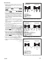
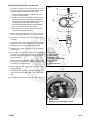
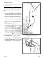
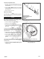
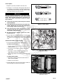
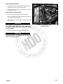
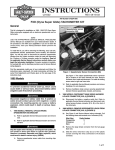
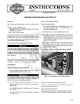
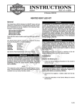
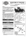
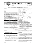
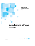
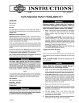
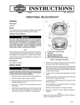
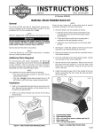
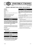
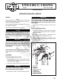
INSTRUCTIONS
REV. 10-01-2004
-J03497
®
Kit Number 69286-05A
SPRINGER AUXILIARY LAMP KIT
General
NOTE
Auxiliary/fog lamps are not included in this kit. The lamps must
be purchased separately. HDI (International) motorcycles
should only use approved fog lamps.
These kits are not compatible with Handlebar Reservoir Cover
Sets 46098-98 or 46099-98.
1WARNING
Stop the engine when refueling or servicing the fuel
system. Do not smoke or allow open flame or sparks
near gasoline. Gasoline is extremely flammable and
highly explosive, which could result in death or serious
injury. (00002a)
4. Follow the Service Manual instructions to remove the fuel
tank.
erRemove
mathe
G
.
Existing Hardware
ny
e
.
n
See the Service Parts illustration for kit contents.
NOTE
This instruction sheet references service manual information. A
service manual for the year and model motorcycle is required
for this installation and is available from a Harley-Davidson
dealer.
w
w
Installation
w.
2. Remove the socket head screw (7) and external-tooth
lockwasher (5) from the left side. Save the screw.
o p. d e
Rosto
ck
1WARNING
The rider’s safety depends upon the correct installation
of this kit. If the procedure is not within your capabilities or you do not have the correct tools, have a HarleyDavidson dealer perform the installation. improper
installation of this kit could result in death or serious
injury. (00308a)
1. See Figure 1. Remove the socket head screw (4) and the
brake line P-clamp (8) from the right side of the rigid fork.
Save the P-clamp.
3. Remove the original acorn nut (1), a flat washer (2) and
bolt (3) holding the upper shock absorber. Save the washers and the acorn nut.
5
i06866
8
4
sh
CAUTION
When installing any electrical accessory, be certain not to
exceed the maximum amperage rating of the fuse or circuit breaker protecting the affected circuit being modified.
Exceeding the maximum amperage can lead to electrical
failures, which could result in death or serious injury.
(00310b)
2
h d o nli
Prepare the Motorcycle for Service
n
e
7
3
2
6
1
1. For EFI models: Follow the Service Manual instructions to purge the fuel supply of high pressure gasoline
and remove the fuel supply line.
2. Follow Service Manual instructions to remove the seat.
1WARNING
To prevent accidental vehicle start-up, which could
cause death or serious injury, disconnect negative (–)
battery cable before proceeding. (00048a)
3. Disconnect the negative (–) battery cable from the battery.
1.
2.
3.
4.
5.
6.
7.
8.
Acorn nut
Washer (2)
3/8” Bolt
Screw, 1/2 in. long
Lockwasher
Shock absorber
Screw, 3/8 in. long
Brake line P-clamp
Figure 1. Mounting Hardware
1 of 8
Mount the Bracket
i06817
1. Identify the correct length 3/8 -16 UNC screw for the combination of accessories and add a flat washer from the
shock absorber bolt.
1992 and Earlier
1993 and Later
Without horn kit: See the Service Parts illustration.
Select the 3/8”-16 x 2-1/2 in. cap screw (9) from the auxiliary lamp kit.
With horn kit: Select the 3/8”-16 x 3 in. silver-finished
screw from the horn kit.
2. With the auxiliary lamp support bracket (7) positioned with
the wiring holes facing downward, assemble the support
bracket and accessories in combination to the upper shock
mount sliding the selected screw through the combination.
For the combination of support bracket, windshield
and horn: See Figure 2.
3
3
3
2
1.
2.
3.
4.
5.
2
5
i06818
w
w
w.
1993 and Later
1992 and Earlier
3
1
2
1.
2.
3.
4.
5.
3
2
4
1
5
5
3
1
3
2
2
4
Horn bracket
.09” (2.3 mm) spacer from horn kit
Lamp support bracket
Upper shock mount
Spacer
e
Figure 3. Auxiliary Lamps and Horn Combination
6. Apply Loctite® 243 (blue) to the threads and tighten the
upper shock mounting bolts to 45-50 ft-lbs (61.0-67.8 Nm).
h d o nli
7. Tighten the left and right rigid fork socket head screws
securely.
2
Horn bracket
Windshield bracket
Lamp support bracket
Spacer
Upper shock mount
o p. d e
5. Obtain the 5/16”-24 x 7/8 in. socket head screw (11) and
another 5/16 in. internal tooth lockwasher (12) from the kit.
Apply Loctite® 243 (blue) to the threads and fasten the
screw and lockwasher through the brake line P-clamp and
through the right-side long auxiliary-lamp support bracket
long tab to the rigid fork.
5
2
Figure 2. Support, Windshield and Horn Combination
3. Fasten with the flat washer and acorn nut removed from
the shock absorber mount.
4. See the Service Parts illustration. Apply Loctite® 243 (blue)
to the threads and install the original 5/16”-24 x 1/2 in.
socket head screw removed from the right side of the rigid
fork, and a 5/16 in. internal tooth lockwasher (12) from the
kit onto the left side to fasten the auxiliary lamp bracket
long tab to the rigid fork.
1
4
sh
For the combination of support bracket and windshield: See Figure 4.
3
4
1
erman
G
.
e
.
y
n
For the combination of support bracket and horn: See
Figure 3.
Rosto
ck
1
i06819
n
1993 and Later
1992 and Earlier
1
2
2
1
4
1.
2.
3.
4.
3
3
2
1
2
4
Windshield bracket
Lamp support bracket
Spacer
Upper shock mount
Figure 4. Auxiliary Lamps and Windshield Combination
-J03497
2 of 8
Install and Wire the Auxiliary Lamp Housings
i06838
6
1. See Figure 5. With the open end facing the rear of the
motorcycle, fit the U-clamp (1) around the support bracket
(2) and assemble the lamp housing to the bracket.
a. Hold the U-clamp and fit the bevel washers (3) to the
curve of the support bracket.
5
4
1
b. With the convex side of the Belleville washer (4) facing
the lamp housing, thread the gray/black (GR/BK) wire
(5) from the housing through the Belleville washer and
then through the clamp and the 2 bevel washers.
2
3
c. Fit the housing threaded stud (6) through the Belleville
washer, the U-clamp and the bevel washers.
d. Slip a washer (7) over the wire and housing stud and
secure with the chrome acorn nut (8).
7
2. See the Service Parts illustration. Locate the outer trim
ring (18), inner nesting ring (21), screw (19), and nut (20).
8
r
e
m
G
an
e.
.
y
n
3. Place the inner nesting ring on the lamp bulb (purchased
separately).
Rosto
ck
4. See Figure 6. Connect the black wire to the bulb spade
terminal (2) next to the bulb indexing tab (1) on the bulb.
Install the gray wire on the remaining spade terminal.
5. Install the trim ring with the bulb in the housing with the
screw and nut.
U-clamp
Support bracket
Bevel washer
Belleville washer
Gray/black wire (GR/BK)
Housing stud
Washer
Chrome acorn nut
o p. d e
7. See the Service Parts illustration. Slide conduit (17) over
each wire, until the end of the conduit is 2 inches inside
the exit hole of the support bracket.
1.
2.
3.
4.
5.
6.
7.
8.
8. Trim the opposite end of the conduit to expose a short
length of lamp wire
9. Secure the wires to the inside of the right-side long mounting tab on the support bracket with 2 short cable straps
(14).
w
w
w.
Figure 5. Auxiliary Lamp Bulb Terminals
sh
6. Use fish tape or wire to draw the lamp wire leads through
the holes in the support bracket, along the inside of the
bracket and through the single exit hole inside the left side
long mounting tab.
i06820
h d o nli
10. Install button plugs (8) in both ends of the support bracket.
n
e
3
1
2
2
1.
2.
3.
Bulb index tab
Spade terminal
Nesting ring index tab (2002 and later)
Figure 6. Auxiliary Lamp Bulb Terminals
-J03497
3 of 8
Route the Wiring Harness
i06821
1. See Figure 7. Place the relay (1) of the wire harness in the
opening of the seat pan.
3
CAUTION
When routing wires through the frame and front fork,
make sure the wires are clear of moving parts, heat
source and pinch points to avoid a possible short circuit.
4
6
2. Route the black ring terminated wire (2) to a ground stud.
3. Find the B+ connector [160B] on the main wiring harness
and route the white wire with connector (7) to the B+ connector.
7
2
4. Route the long center conduit along the frame backbone.
5. Turn the lamp switch (3) and the lamp circuit conduit (6) to
the left side of the motorcycle.
erman
G
.
e
.
y
n
6. Route the unterminated white wire to the headlamp.
Rosto
ck
7. Cable tie the long center harness to the main wiring harness.
Install the Lamp Switch
1
3. Route the switch wires along the underside of the left handlebar push the switch (28) through the bracket opening
and thread on the rubber switch boot (24).
NOTE
See the Service Parts illustration. If the boot (25) becomes
worn or damaged, or is lost, replace the boot to prevent moisture from entering the switch
w
w
w.
1.
2.
3.
4.
5.
6.
7.
Relay
Ground (BK)
Lamp switch
Un-terminated (W)
Fuse holder w/15 Amp fuse
Lamp circuit
Wire wire with B+ connector
sh
2. See Service Parts illustration. Mount the switch bracket
(25) to the switch housing and tighten to 60-80 in-lbs (7-9
Nm)
5
o p. d e
1. See Figure 8. Remove the lower screw and washer from
the left handlebar switch housing clamp.
Figure 7. Auxiliary Lamp Wire Harness
h d o nli
4. Replace the wire clips (16) in the handlebar capturing the
auxiliary lamp switch wire.
i02280
n
e
5. For International (HDI) models: Place the fog lamp
(HDI) switch label (27) on the clutch control clamp.
Figure 8. Lamp Switch Mounting
-J03497
4 of 8
Connect the Lamp Switch Circuit
1
1. See Figure 9. Route the unterminated black wire (2) from
the harness to the 2 lamp wires and slide heat shrink tubing
over the black wire.
i02295.eps
2
3
2. Follow the 2 into 1 Splice. instructions on the next page
to splice the black wire from the wire harness to the 2 lamp
gray and black wires.
4
5
3. Slide the conduit over the splice.
Splice in the Low Beam
NOTE
The auxiliary lamps can only be operated while the main headlamp is on low beam. This function meets the requirements of
many state and local laws.
CAUTION
1. Heat-shrink tubing
2. Black wire from kit harness
3. Splice connector
4. Lamp wires
5. Conduit
erman
G
.
e
.
y
n
When routing wire through frame and front fork, make sure
wire is clear of moving parts, heat sources and pinch
points to avoid a possible short circuit.
Figure 9. Connect the Lamp Wires to the Kit Harness
Rosto
ck
1. Remove the headlamp trim ring and headlamp.
2. Separate the connector from the bulb.
i02294b
o p. d e
3. See Figure 10. Route the unterminated white wire from the
auxiliary lamp harness through the grommet in the headlight housing.
NOTE
To route the wire through the grommet, push a hooked piece of
wire through the grommet from the inside of the headlamp housing. Soap the white wire and pull it back through the grommet
with the hooked wire.
2
5. Follow the 2 into 1 Splice. instructions on the next page
to splice the cut end of the yellow wire from the connector
to the white and yellow wires from the headlamp housing
grommet.
w
w
w.
h d o nli
NOTE
If the white wire from the harness does not fit through the grommet, the white wire may be spliced to the yellow wire outside the
headlamp housing.
6. Connect the connector to the spade connectors on the
headlamp and install the headlamp and trim ring. in the
headlamp housing.
-J03497
sh
4. Cut the yellow low beam lead 1.5 in. (38.1 mm) from the
headlamp connector to leave sufficient length for a splice.
n
1
e
1. Unterminated white wire from auxiliary lamp
2. Yellow (low beam) wire
Figure 10. Splice the Unterminated Wire to the Headlight
Yellow (low beam) Lead
5 of 8
2 into 1 Splice
i06422
1. Strip 3/8 in. (9.5 mm) of insulation off the wire ends.
2. See Figure 11. Use the blue (14-16 gauge) crimp cavity of
the crimping tool (kent-Moore Part No. HD-38125-8) to
crimp one wire end in one end of the blue connector and 2
wire ends in the other end of the connector.
1WARNING
Be sure to follow manufacturer’s instructions when
using the UltraTorch UT-100 or any other radiant heating
device. Failure to follow manufacturer’s instructions can
cause a fire, which could result in death or serious
injury. (00335a)
Always keep hands away from tool tip area and heat
shrink attachment.
●
Avoid directing the heat toward any fuel system component. Extreme heat can cause fuel ignition/explosion resulting in death or serious injury.
●
Avoid directing heat toward any electrical system
component other than the connectors on which heat
shrink work is being performed.
●
Rosto
ck
●
Figure 11. 2 into 1 Splice
erman
G
.
e
.
y
n
i06825
Be sure to turn the “ON/OFF” switch to the “OFF”
position after use.
o p. d e
3. Use the Ultra Torch UT-100 (Kent-Moore Part No. HD39969) or other radiant heater to heat from the center of
the crimp out each end until the sealant comes out both
ends.
Connect the Auxiliary Lamps to Power
1. Connect the white (power) lead to a power source.
For 2003 and earlier models:
b. See Service Parts illustration. Crimp the ring terminal
(on the lead.
w
w
c. See Figure 11. Remove the nut on the copper stud
(BAT) terminal of the main circuit breaker.
w.
sh
a. Cut the connector from the white power lead on the
lamp wire harness.
h d o nli
d. Add the ring terminal on the white power lead and install
the nut.
For 2004 and later models:
e
Figure 11. Electrical Panel and Main Circuit Breaker
(2003 FXST shown)
n
i06828
a. See Figure 12. Route the white wire and connector to
the B+ connector [160B].
b. Mate the connector halves.
2. Use the cable ties to secure any excess wire to the bike to
prevent damage or interference with operation.
Figure 12. B+ Connector [160B]
(2004 FXST shown)
-J03497
6 of 8
Ground the Auxiliary Lamps
i06825
1. See Figure 13. Route the ring terminated wire (BK) to the
ground stud or any good electrical ground point.
2. Remove the nut and add the ring terminal to the ground
stud. Tighten the bolt.
Return the Motorcycle to Service
1. Connect the negative (–) battery cable to the battery.
2. Turn the IGNITION switch to ON and test the auxiliary lamp
switch and the lamps for operation.
3. Aim the lamps forward, then tighten the lamp mounting
nuts securely.
1WARNING
After installing seat, pull upward on front of seat to be sure
it is in locked position. While riding, a loose seat can shift
causing loss of control, which could result in death or serious injury. (00070a)
Figure 13. Ground Wire Location
(1999 FXST shown)
erman
G
.
e
.
y
n
4. Follow Service Manual instructions to install the seat.
w
w
-J03497
o p. d e
sh
Rosto
ck
1WARNING
Be sure that all lights and switches operate properly before
operating motorcycle. Low visibility of rider can result in
death or serious injury. (00316a)
w.
h d o nli
n
e
7 of 8
®
Service Parts
i06815
Date 10/04
Part No. 69286-05A
Springer Auxiliary Lamp Kit
1
17
18
21
3
16
5
11
15
10
7
8
4
6
Rosto
ck
20
9
erman
G
.
e
.
y
n26
12
13
o p. d e
19
14
-J03497
w
w.
Part No.
68683-02
69104-04
6072
58114-88
58115-88
6333
68781-88A
68796-88
4032A
5791
4387
7127
10006
10065
70586-93
70345-84
not sold
68725-62A
3514
7606
68331-02
72266-94
9858
67880-94
Not sold
7892
Not sold
70370-00
24
i
h d o n l 23
28
sh
Description (Qty)
Auxiliary lamp housing (2)
Wire harness
Belleville washer (2)
“U”-clamp (2)
Bevel washer (4)
Flat washer (2)
Bracket, passing lamp support
Plug button (2)
Cap screw, hex socket, 3/8-16 x 2-1/2
Spacer, 0.09” (2.3 mm) thick (2)
Screw, hex socket, button head 5/16-24 x 7/8
Lockwasher, 5/16 inch internal tooth (2)
Cable strap, 7.5” (190 mm) (4)
Cable strap, 5.5” (140 mm) (2)
Butt splice connector, blue (3)
Harness retainer (2)
Conduit, black vinyl, 18” (.46 M)
Bezel trim ring (2)
Screw (2)
Nut (2)
Inner nesting ring (2)
Shrink tube
Ring terminal, pre-insulated
Switch boot
Switch bracket
Acorn nut (2)
Lamp switch label (HDI)
Switch
w
Item
1
2
3
4
5
6
7
8
9
10
11
12
13
14
15
16
17
18
19
20
21
22
23
24
25
26
27
28
n
25
e
22
2
27
8 of 8