1
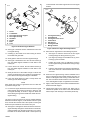
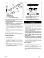
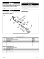
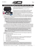
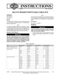
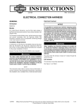
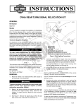
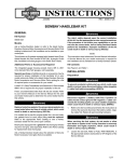
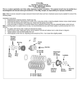
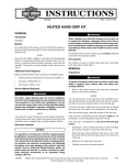
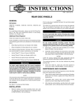
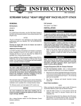
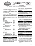
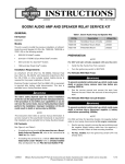
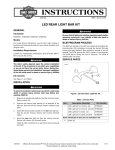
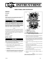
-J02427
REV. 2002-07-17
DIRECTIONAL RELOCATION KIT
GENERAL
2
is01051
Kit Number
3
53933-03
4
Models
This kit relocates the rear turn signals on 2003 and later Softail®
model motorcycles except FXSTD and FLSTC models
1
Additional Parts Required
5
The rider's safety depends upon the correct installation
of this kit. Use the appropriate service manual procedures.
If the procedure is not within your capabilities or you do
not have the correct tools, have a Harley-Davidson dealer
perform the installation. Improper installation of this kit
could result in death or serious injury. (00333a)
3
4
NOTE
1.
2.
3.
4.
5.
This instruction sheet references Service Manual information.
A Service Manual for your model motorcycle is required for
this installation and is available from a Harley-Davidson Dealer.
Loctite® 243 (blue) Part Number 99642-99 is available from a
Harley-Davidson Dealer.
FLSTF, FLSTS model tail light
Lock tabs
Left turn signal connector
Right turn signal connector
FXST, FXSTB, FXSTS model tail light
Figure 1. Turn Signal Connectors
Kit Contents
6.
Remove the turn-signal connectors and wires through the
openings on each side of the tail-lamp base.
7.
To prevent accidental vehicle start-up, which could cause
death or serious injury, disconnect battery cables (negative
(-) cable first) before proceeding. (00307a)
Reach under the fender to locate the fender clips fastening
the turn-signal wires in place. Carefully pull the wires out
of the clips, and pull the turn-signal connectors and wires
out from under the fender.
8.
On each set of turn-signal wires hanging from under the
fender:
1.
Remove the seat according to service-manual instructions.
•
2.
Disconnect battery cables, negative cable first.
Remove a 2-inch (51 mm) section of conduit 4 inches (100
mm) from the turn-signal connectors.
3.
Raise the motorcycle on a floor jack to lower the rear wheel
for fender-hardware access.
•
Cut the black turn-signal wire about 5-1/2 inches (140 mm)
from its connector.
4.
See Figure 1. Remove the screws fastening the lens to
the tail lamp.
•
Cut the violet/brown turn-signal wire about 4-1/2 inches
(114 mm) from its connector.
5.
Inside the tail lamp assembly, use a terminal pick or small
screw driver to press the locktabs on, and unplug, the
connectors on black and violet/brown turn-signal wires .
•
Save the cut wires with their turn-signal connectors.
9.
Remove the sissy bar and/or sideplate assembly, if
equipped.
See Figure 6 and Table 1.
INSTALLATION
NOTE
Support the fender before removing the fender hardware to
prevent scratching the fender paint.
-J02427
1 of 4
is01040
of wire between the fender supports and the turn-signal
sockets.
1
8
is01054
7
2
7
4
3
3
1
6
6
5
5
2
4
1.
2.
3.
4.
5.
6.
7.
8.
Screw
Lockwasher
Turn-signal housing support
Turn-signal housing
Grommet
Socket
Bulb
Lens
Figure 2. Stock Turn-Signal Removal
1.
2.
3.
4.
5.
6.
7.
Turn signal housing
Threaded hole
Turn signal recess cover
Lock washer
Hex jam nut
Turn signal stud
Wiring exit hole
Figure 3. Rear Turn Signal Assembly To Stud
10. See Figure 2. Remove the lens and bulb from each rear
turn-signal housing.
19. Route the turn signal wires in the following sequence:
11. Carefully pry the socket out of each housing to remove
the sockets and grommets.
a.
See Figure 3. Insert the wires from the turn signal
housing through the wiring exit hole (7), and
12. Gently pull the wires out of the turn-signal housings.
b.
13. See Figure 4. Remove the four mid- and rear screws (2)
from the fender-support brackets on both sides of the
motorcycle.
(see Figure 3) through the threaded hole (2) in the
housing (1) from the inside.
c.
14. Loosen, but do not remove, the two forward screws (3)
from the fender-support brackets on both sides of the
motorcycle.
Position the recess cover (3) against the recess in
the turn signal housing, with the wires coming through
the hole.
d.
Insert the wires into the end of the turn signal bar (6),
and out the wire hole a short distance from the end
of the bar.
15. Gently lift the rear of the fender enough to remove the
screws (4) fastening the turn signals to the fender supports. Save the turn-signal housings for installation.
16. Lower the fender back into place. Loosely fasten the
screws (2) to the fender support.
NOTE
Apply liquid soap to the turn signal wires and use a thin wire
to pull wires through stud.
17. For each turn signal, thread the wires from the turn-signal
socket through the grommet, as shown in Figure 2, and
turn-signal assembly, as shown in Figure 6. Route the
wires starting through the threaded hole inside the turnsignal housing.
20. Screw the turn signal housing onto the threaded end of
the turn signal stud, being careful that the wires are not
twisted or damaged as the housing is assembled to the
bar. The lock washer will fit inside the hole in the recess
cover. Hand tighten the jam nut against the lock washer.
21. Apply Loctite® 243 (blue) to the stud threads between the
fender and fender support.
22. Thread each stud into the special nuts, taking care to
maintain the position of the notch in the note described
above. Torque each stud (6) to 18-22 ft-lbs (24-30 Nm).
NOTE
The notch cut into the special nut must be installed between
the fender and fender support, on the threads of the turn-signal
stud, and with the notched-side of the special nut facing the
fender and open toward the front of the motorcycle.
18. See Figure 3 and Figure 6. Route the wires for each turnsignal assembly through the rearmost hole in the fendersupport bracket, then through the special nut (7) and to
the inside of the fender. Allow about 6 inches (150 mm)
-J02427
2 of 4
is01038
is01037
3
1
4
1
2
5
1.
2.
3.
4.
5.
2
Fender support bracket
Screws
Forward screws
Turn signal screws
On FLSTF, FLSTS only
3
1. Stripped wire ends inserted into connector
2. Wire ends crimped in connector
3. Connector after heat has been applied
Figure 4. Hardware Removal
23. See Figure 4. Torque the fender-support screws (2) and
(3) to 21-27 ft-lbs (28-37 Nm).
Figure 5. Sealed Butt-Splice Connections
24. See Figure 6. Loosely fasten the jam nuts (5) and washers
(4) onto the studs (6).
25. Screw the turn-signal housings onto the studs while preventing the turn-signal socket wires from twisting.
26. Align the rear turn-signal housing so the lens, when
installed, faces rearward for proper visibility. Torque the
jam nut (5) against the housing to 96-120 in-lbs (11-13
Nm).
27. While pulling the turn-signal wires into the inside of the
fender, guide each turn-signal socket and grommet into
its housing.
28. Install the turn-signal bulbs and lenses.
29. Fasten a chrome hole plug (1) into the remaining hole in
the fender support.
Be sure to follow manufacturer's instructions when using
the UltraTorch UT-100 or any other radiant heating device.
Failure to follow manufacturer's instructions can cause a
fire, which could result in death or serious injury. (00335a)
•
Always keep hands away from tool tip area and heat
shrink attachment.
•
Avoid directing the heat toward any fuel system
component. Extreme heat can cause fuel ignition/explosion resulting in personal injury.
•
Avoid directing heat toward electrical system components other than the connectors on which heat-shrink
work is being performed.
•
Be sure to turn the "ON/OFF" switch to the "OFF"
position after use.
4.
See Figure 5. Use an UltraTorch UT-100 (HD-39969),
Robinair Heat Gun (Kent-Moor Part Number HD-25070)
with Heatshrink Attachment (HD-41183), or other suitable
radiant heating device to heat-shrink the jacket of the buttsplice connector to the wire. Apply heat from the center
of the crimp outward to the crimp ends until the sealant
encloses both ends of the connector.
Butt-Splice Connections
1.
Strip 3/8 inch (10 mm) of insulation from the cut ends of
the turn-signal wires.
2.
See Figure 5. Splice each set of cut wires into butt splice
connectors. Connect Black to Black in one connector, and
Violet/Brown to Violet/Brown in the other connector.
Repeat the splice for both left and right turn-signal wire
sets.
3.
Match the color of the butt-splice connector with the color
of the crimp cavity on the crimping tool. Use the crimping
tool (Kent-Moore Part Number HD-38125-8) or equivalent
to crimp the wires into the connector.
-J02427
FINAL ASSEMBLY
1.
Fasten the wires, in conduit, to the clips inside the fender.
2.
Route the wires into the tail-lamp housing.
3.
Fasten the turn-signal-wire connectors to their respective
connections inside the tail-lamp housing.
4.
Install the tail-lamp lens. Tighten to 20-24 in-lbs. (2.3-2.7
Nm).
3 of 4
6.
Connect positive (+) battery cable first. If positive (+) cable
should contact ground with negative (-) cable connected,
the resulting sparks can cause a battery explosion, which
could result in death or serious injury. (00068a)
5.
Check the turn signals for proper operation.
After installing seat, pull upward on seat to be sure it is
locked in position. While riding, a loose seat can shift
causing loss of control, which could result in death or
serious injury. (00070b)
Connect the battery cables to the battery, positive cable
first.
7.
Install the seat according to the service-manual instructions.
SERVICE PARTS
Be sure that all lights and switches operate properly before
operating motorcycle. Low visibility of rider can result in
death or serious injury. (00316a)
is01036
B
A
C
2
1
7
D
E
6
5
4
3
Figure 6. Service Parts: Directional Relocation Kit
Table 1. Service Parts Table
Item
Description (Quantity)
Part Number
1
Chrome hole plug (2)
53830-00
2
Butt-splice wire connector, 18-22 ga. (4)
70585-93
3
Recess cover (2)
68000-02
4
Lockwasher (2)
7042
5
Jam nut (2)
68991-02
6
Rear directional stud (2)
53663-03
7
Nut, special (2)
68900-03
Items shown, but not included in kit:
A
Left-side installed orientation shown
B
Fender support bracket
C
Stock screws
D
Wrench flats on stud
E
Stock turn-signal housing
-J02427
4 of 4