1
SPLIT-TYPE, HEAT PUMP AIR CONDITIONERS
February 2014
No. OCH547
HFC
utilized
TECHNICAL & SERVICE MANUAL
<Outdoor unit>
[Model Name]
PUMY-P112VKM
PUMY-P125VKM
PUMY-P140VKM
PUMY-P112YKM
PUMY-P125YKM
PUMY-P140YKM
Salt proof model
PUMY-P112VKM-BS
PUMY-P125VKM-BS
PUMY-P140VKM-BS
PUMY-P112YKM-BS
PUMY-P125YKM-BS
PUMY-P140YKM-BS
[Service Ref.]
PUMY-P112VKM
PUMY-P125VKM
PUMY-P140VKM
PUMY-P112YKM
PUMY-P125YKM
PUMY-P140YKM
R410A
Note:
• This service manual
describes technical data of
the outdoor units only.
PUMY-P112VKM-BS
PUMY-P125VKM-BS
PUMY-P140VKM-BS
PUMY-P112YKM-BS
PUMY-P125YKM-BS
PUMY-P140YKM-BS
CONTENTS
SAFETY PRECAUTION....................................2
OVERVIEW OF UNITS......................................5
SPECIFICATIONS.............................................7
DATA................................................................9
OUTLINES AND DIMENSIONS......................20
WIRING DIAGRAM.........................................22
NECESSARY CONDITIONS FOR SYSTEM CONSTRUCTION.....24
8. TROUBLESHOOTING....................................34
9. ELECTRICAL WIRING...................................123
10. REFRIGERANT PIPING TASKS....................127
11. DISASSEMBLY PROCEDURE.......................131
1.
2.
3.
4.
5.
6.
7.
Model name
indication
OUTDOOR UNIT
PARTS CATALOG (OCB547)
1
SAFETY PRECAUTION
1-1. CAUTIONS RELATED TO NEW REFRIGERANT
Cautions for units utilizing refrigerant R410A
Use new refrigerant pipes.
Use a vacuum pump with a reverse flow check
valve.
Avoid using thin pipes.
Vacuum pump oil may flow back into refrigerant cycle and
that can cause deterioration of refrigerant oil etc.
Make sure that the inside and outside of refrigerant piping is clean and it has no contaminants
such as sulfur, oxides, dirt, shaving particles, etc,
which are hazard to refrigerant cycle.
In addition, use pipes with specified thickness.
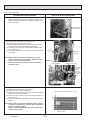
Use the following tools specifically designed for
use with R410A refrigerant.
The following tools are necessary to use R410A refrigerant.
Gauge manifold
Charge hose
Gas leak detector
Torque wrench
Contamination inside refrigerant piping can cause deterioration of refrigerant oil etc.
Store the piping indoors, and both ends of the
piping sealed until just before brazing.
(Leave elbow joints, etc. in their packaging.)
If dirt, dust or moisture enters into refrigerant cycle, that can
cause deterioration of refrigerant oil or malfunction of compressor.
The refrigerant oil applied to flare and flange
connections must be ester oil, ether oil or
alkylbenzene oil in a small amount.
If large amount of mineral oil enters, that can cause deterioration of refrigerant oil etc.
Charge refrigerant from liquid phase of gas
cylinder.
If the refrigerant is charged from gas phase, composition
change may occur in refrigerant and the efficiency will be
lowered.
Do not use refrigerant other than R410A.
If other refrigerant (R22 etc.) is used, chlorine in refrigerant can cause deterioration of refrigerant oil etc.
OCH547
Tools for R410A
Flare tool
Size adjustment gauge
Vacuum pump adaptor
Electronic refrigerant
charging scale
Handle tools with care.
If dirt, dust or moisture enters into refrigerant cycle, that can
cause deterioration of refrigerant oil or malfunction of compressor.
Do not use a charging cylinder.
If a charging cylinder is used, the composition of refrigerant will change and the efficiency will be lowered.
Ventilate the room if refrigerant leaks during
operation. If refrigerant comes into contact with
a flame, poisonous gases will be released.
Use the specified refrigerant only.
Never use any refrigerant other than that specified.
Doing so may cause a burst, an explosion, or fire when the
unit is being used, serviced, or disposed of.
Correct refrigerant is specified in the manuals and on the
spec labels provided with our products.
We will not be held responsible for mechanical failure,
system malfunction, unit breakdown or accidents caused
by failure to follow the instructions.
2
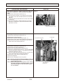
[1] Cautions for service
(1) Perform service after recovering the refrigerant left in unit completely.
(2) Do not release refrigerant in the air.
(3) After completing service, charge the cycle with specified amount of refrigerant.
(4) When performing service, install a filter drier simultaneously.
Be sure to use a filter drier for new refrigerant.
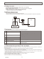
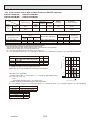
[2] Additional refrigerant charge
When charging directly from cylinder
· Check that cylinder for R410A on the market is syphon type.
· Charging should be performed with the cylinder of syphon stood vertically. (Refrigerant is charged from liquid phase.)
Unit
Gravimeter
[3] Service tools
Use the below service tools as exclusive tools for R410A refrigerant.
No.
1
Tool name
Gauge manifold
Specifications
· Only for R410A
· Use the existing fitting specifications. (UNF1/2)
· Use high-tension side pressure of 5.3MPa·G or over.
2
Charge hose
· Only for R410A
· Use pressure performance of 5.09MPa·G or over.
3
—
Electronic scale
4
Gas leak detector
· Use the detector for R134a, R407C or R410A.
· Attach on vacuum pump.
5
Adaptor for reverse flow check
6
Refrigerant charge base
7
Refrigerant cylinder
—
· Only for R410A
· Top of cylinder (Pink)
· Cylinder with syphon
8
—
Refrigerant recovery equipment
1-2. PRECAUTIONS FOR SALT PROOF TYPE "-BS" MODEL
Although "-BS" model has been designed to be resistant to salt damage, observe the following precautions to maintain the
performance of the unit.
1. Avoid installing the unit in a location where it will be exposed directly to seawater or sea breeze.
2. If the cover panel may become covered with salt, be sure to install the unit in a location where the salt will be washed away by
rainwater. (If a sunshade is installed, rainwater may not clean the panel.)
3. To ensure that water does not collect in the base of the outdoor unit, make sure that the base is level, not at angle. Water
collecting in the base of the outdoor unit could cause rust.
4. If the unit is installed in a coastal area, clean the unit with water regularly to remove any salt build-up.
5. If the unit is damaged during installation or maintenance, be sure to repair it.
6. Be sure to check the condition of the unit regularly.
7. Be sure to install the unit in a location with good drainage.
OCH547
3
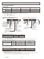
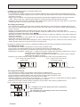
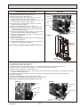
Cautions for refrigerant piping work
New refrigerant R410A is adopted for replacement inverter series. Although the refrigerant piping work for R410A is same
as for R22, exclusive tools are necessary so as not to mix with different kind of refrigerant. Furthermore as the working
pressure of R410A is 1.6 times higher than that of R22, their sizes of flared sections and flare nuts are different.
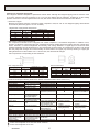
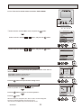
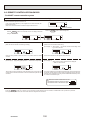
1 Thickness of pipes
Because the working pressure of R410A is higher compared to R22, be sure to use refrigerant piping with thickness
shown below. (Never use pipes of 0.7 mm or below.)
Diagram below: Piping diameter and thickness
Thickness (mm)
Nominal
Outside
dimensions(inch) diameter (mm)
R410A
R22
0.8
0.8
6.35
1/4
0.8
0.8
9.52
3/8
0.8
0.8
12.70
1/2
1.0
1.0
15.88
5/8
—
1.0
19.05
3/4
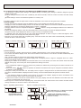
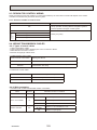
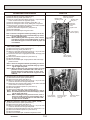
2 Dimensions of flare cutting and flare nut
The component molecules in HFC refrigerant are smaller compared to conventional refrigerants. In addition to that,
R410A is a refrigerant, which has higher risk of leakage because its working pressure is higher than that of other refrigerants. Therefore, to enhance airtightness and intensity, flare cutting dimension of copper pipe for R410A has been
specified separately from the dimensions for other refrigerants as shown below. The dimension B of flare nut for R410A
also has partly been changed to increase intensity as shown below. Set copper pipe correctly referring to copper pipe
flaring dimensions for R410A below. For 1/2 and 5/8 inch, the dimension B changes.
Use torque wrench corresponding to each dimension.
Dimension A
Dimension B
Flare cutting dimensions
Nominal
Outside
dimensions(inch) diameter (mm)
6.35
1/4
9.52
3/8
12.70
1/2
15.88
5/8
19.05
3/4
Flare nut dimensions
Outside
Nominal
dimensions(inch) diameter (mm)
6.35
1/4
9.52
3/8
12.70
1/2
15.88
5/8
19.05
3/4
Dimension A ( +0
-0.4 ) (mm)
R410A
R22
9.0
9.1
13.0
13.2
16.2
16.6
19.4
19.7
—
23.3
Dimension B (mm)
R410A
R22
17.0
17.0
22.0
22.0
24.0
26.0
27.0
29.0
—
36.0
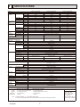
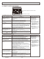
3 Tools for R410A (The following table shows whether conventional tools can be used or not.)
Tools and materials
Gauge manifold
Charge hose
Gas leak detector
Refrigerant recovery equipment
Refrigerant cylinder
Applied oil
R410A tools
Can R22 tools be used? Can R407C tools be used?
Tool exclusive for R410A
Tool exclusive for R410A
Tool for HFC refrigerant
Tool exclusive for R410A
Tool exclusive for R410A
Ester oil, ether oil and
Ester oil, ether oil:
Alkylbenzene oil: minimum amount
alkylbenzene oil (minimum amount)
Safety charger
Prevent compressor malfunction Tool exclusive for R410A
when charging refrigerant by
spraying liquid refrigerant
Charge valve
Prevent gas from blowing out Tool exclusive for R410A
when detaching charge hose
Vacuum pump
Tools for other refrigerants can
(Usable if equipped
(Usable if equipped
Vacuum drying and air
with adopter for reverwith adopter for reverbe used if equipped with adoppurge
se flow)
se flow)
ter for reverse flow check
Tools for other refrigerants
Flare tool
(Usable by adjusting
(Usable by adjusting
Flaring work of piping
can be used by adjusting
flaring dimension)
flaring dimension)
flaring dimension
Bend the pipes
Tools for other refrigerants can be used
Bender
Pipe cutter
Cut the pipes
Tools for other refrigerants can be used
Welder and nitrogen gas cylinder Weld the pipes
Tools for other refrigerants can be used
Refrigerant charging scale Refrigerant charge
Tools for other refrigerants can be used
Vacuum gauge or thermis- Check the degree of vacuum. (Vacuum Tools for other refrigerants
valve prevents back flow of oil and refri- can be used
tor vacuum gauge and
gerant to thermistor vacuum gauge)
vacuum valve
Refrigerant charge
Charging cylinder
Tool exclusive for R410A
: Prepare a new tool. (Use the new tool as the tool exclusive for R410A.)
: Tools for other refrigerants can be used under certain conditions.
: Tools for other refrigerants can be used.
OCH547
Use
Air purge, refrigerant charge
and operation check
Gas leak check
Refrigerant recovery
Refrigerant charge
Apply to flared section
4
2
OVERVIEW OF UNITS
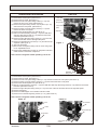
2-1. UNIT CONSTRUCTION
4HP
Outdoor unit
Cassette Ceiling
2-way flow
15
PLFY-P
-
PLFY-P
-
20
20VCM-E(2)
20VLMD-E
20VBM-E
25
25VCM-E(2)
25VLMD-E
25VBM-E
32VLMD-E
32VBM-E
40VLMD-E
40VBM-E
Capacity
32
40
32VCM-E(2)
32VBM-E
40VCM-E(2)
40VBM-E
1-way flow
PMFY-P
-
50
50VBM-E
50VLMD-E
–
63
63VBM-E
63VLMD-E
–
71
–
–
–
80
80VBM-E
80VLMD-E
–
100
100VBM-E 100VLMD-E
–
125
125VBM-E 125VLMD-E
–
140
–
–
–
PUMY-P140VKM(-BS)
PUMY-P140YKM(-BS)
Type 15 ~ Type 140
1 ~ 9 unit
1 ~ 12 unit
1 ~ 10 unit
50% ~130% of outdoor unit capacity *2 *3
Branching pipe
components
4-way flow
6HP
PUMY-P125VKM(-BS)
PUMY-P125YKM(-BS)
Type 15 ~ Type 125
Capacity
Applicable
indoor unit Number of units
Total system wide capacity
Model
5HP
PUMY-P112VKM(-BS)
PUMY-P112YKM(-BS)
CMY-Y62-G-E
CMY-Y64-G-E
CMY-Y68-G-E
Branch header
(2 branches)
Branch header
(4 branches)
Branch header
(8 branches)
Exposed
Concealed
Ceiling
Concealed
(Fresh Air) *1
Air to Water
Unit *3
PFFY-P
–
20VLEM-E
PFFY-P
–
PEFY-P
–
PWFY-P
–
20VLRM-E
–
–
25VLRM-E
–
–
32VLRM-E
–
–
40VLRM-E
–
–
50VLEM-E 50VLRM-E
–
–
63VKM-E 63VLEM-E 63VLRM-E
–
–
Ceiling
Concealed
Wall
Mounted
Ceiling
Suspended
PEFY-P
15VMS1(L)-E
20VMS1(L)-E
/ VMA(L)-E
PKFY-P
15VBM-E
PCFY-P
–
20VBM-E
–
25VMS1(L)-E
/ VMA(L)-E
25VBM-E
–
32VMS1(L)-E
/ VMA(L)-E
32VHM-E
–
40VHM-E
40VKM-E
50VHM-E
–
40VMS1(L)-E
/ VMA(L)-E/ VMH-E
50VMS1(L)-E
/ VMA(L)-E/ VMH-E
63VMS1(L)-E
/ VMA(L)-E/ VMH-E
71VMA(L)-E
/ VMH
80VMH-E
/ VMA(L)-E
100VMH-E
/ VMA(L)-E
125VMH-E
/ VMA(L)-E
140VMH-E
/ VMA(L)-E
63VKM-E
Floor standing
VKM-E(2)
25VLEM-E
VKM-E(2)
32VLEM-E
VKM-E(2)
40VLEM-E
VKM-E(2)
–
–
–
–
–
–
–
–
–
–
80VMH-E-F
–
–
–
–
100VM-E-AU
100VKM-E 100VKM-E
–
125VKM-E
–
–
–
–
–
–
–
–
140VMH-E-F
–
CONNECTION KIT
PAC-LV11M-J
M series indoor unit *4
MSZ-SF Series
MSZ-EF Series
MSZ-FH Series
Decorative panel
Name
MA remote controller
M-NET remote controller
PAR-F27MEA-E
Remote Model number
controller
• A handy remote controller for use in
conjunction with the Melans centralized
Functions
management system.
• Addresses must be set.
M series remote controller
PAR-21MAA, PAR-30MAA
PAR-W21MAA(when using PWFY)
• Addresses setting is not
necessary.
*1. PUMY is connectable to Fresh Air type indoor unit.
It is possible to connect 1 Fresh Air type indoor unit to 1 outdoor unit. (1:1 system)
Operating temperature range (outdoor temperature) for fresh air type indoor units differ from other indoor units.
Refer to "2-2-(3). Operating temperature range".
*2. When the indoor unit of Fresh Air type is connected with the outdoor unit, the maximum connectable total indoor unit capacity is 110% (100%
in case of heating below -5 : [23 ˚F]).
*3. When connecting PWFY series
• Only 1 PWFY-P100VM-E-AU can be connected. PWFY-P200VM-E-AU and PWFY-P100VM-E-BU cannot be connected.
• The PWFY unit cannot be the only unit connected to an outdoor unit. Select an indoor unit so that the total rated capacity of the indoor
units, excluding the PWFY unit, is 50 to 100% of the outdoor unit capacity.
*4. When connecting the CONNECTION KIT (PAC-LV11M-J) and an M-series indoor unit, refer to the installation manual for the CONNECTION KIT.
OCH547
5
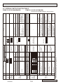
2-2. UNIT SPECIFICATIONS
(1) Outdoor Unit
PUMY-P112VKM(-BS)
PUMY-P112YKM(-BS)
Service Ref.
Capacity
Cooling (kW)
Heating (kW)
Compressor (kW)
PUMY-P125VKM(-BS)
PUMY-P125YKM(-BS)
PUMY-P140VKM(-BS)
PUMY-P140YKM(-BS)
11.2
14.0
15.5
12.5
16.0
18.0
2.9
3.5
3.9
Cooling/Heating capacity indicates the maximum value at operation under the following condition.
*Cooling Indoor : D.B. 27 °C/ W.B. 19.0 °C
Outdoor : D.B. 35 °C
Heating Indoor : D.B. 20 °C
Outdoor : D.B. 7 °C/ W.B. 6 °C
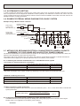
(2) Method for identifying MULTI-S model
Indoor unit < When using Model 80 >
Outdoor unit <When using model 125 >
P L F Y - P 80 V BM - E
PAC type
L : Ceiling cassette
K : Wall-mounted type
E : Hidden skylight type
C : Ceiling suspended type
M : Ceiling cassette type
F : Floor standing type
W: Air to Water Unit
Refrigerant
R407C/R22
R410A
commonness
Frequency
conversion
controller
NEW frequency converter
one-to-many air conditioners
(flexible design type)
PU M Y - P 125 Y K M - BS
Outdoor unit
Sub-number
BM
CM
KM
M
KM
LMD
Refrigerant
R410A
Frequency
conversion
controller
M-NET
control
Indicates equivalent
to Cooling capacity
(k cal / h)
Power supply
V: Single phase
220-230-240V 50Hz
Indicates equivalent
to Cooling capacity
(k cal / h)
M-NET control
MULTI-S
Outdoor unit
model type
Salt proof
type
Power supply
V: Single phase
220-230-240V 50Hz
Y: 3-phase
380-400-415V 50Hz
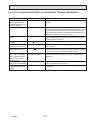
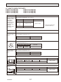
(3) Operating temperature range
Indoor-side intake air temperature
Outdoor-side intake air temperature
Cooling
W.B. 15 to 24 °C
D.B. -5 to 46 °C*
Heating
D.B. 15 to 27 °C
W.B. -20 to 15 °C
Notes
D.B. : Dry Bulb Temperature
W.B. : Wet Bulb Temperature
*10~46 °C D.B. : When connecting PKFY-P15/P20/P25VBM, PFFY-P20/25/32VKM and PFFY-P20/25/32 VLE(R)M type indoor unit.
■ When connecting fresh air type indoor unit
Capacity of Fresh
air type indoor
Cooling
Heating
D.B. 21 to 43 :*
D.B. -10 to 20 :**
W.B. 15.5 to 35 :
D.B. 21 to 43 :*
D.B. -5 to 20 :**
P140
W.B.15.5 to 35 :
*Thermo-OFF (FAN-mode) automatically starts if the outdoor temp. is lower than 21 : D.B..
**Thermo-OFF (FAN-mode) automatically starts if the outdoor temp. is higher than 20 : D.B..
Indoor-side and Outdoor-side
intake air temperature
P80
■ When connecting Air to Water Unit
Indoor-side intake water temperature
Outdoor-side intake air temperature
Cooling
*1
Heating
D.B. 10 to 45 :
*1
W.B.- 20 to 15 :
*1: • PWFY series can operate in Heating mode but not in Cooling mode. An indoor unit other than that of PWFY series can
operate in Cooling mode.
• A PWFY series and other series cannot operate simultaneously.
• The operation of PWFY series takes precedence over other series. While a PWFY series is operating, other series do not operate.
• The set temperature on the remote controller represents the target temperature of the outlet water.
OCH547
6
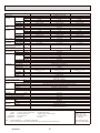
3
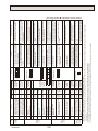
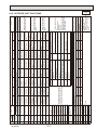
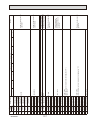
SPECIFICATIONS
Model
Power source
Cooling capacity
(Nominal)
Temp. range of
cooling
PUMY-P112VKM(-BS)
Power input
Current input
COP
Indoor temp.
Outdoor temp.
Heating capacity
(Nominal)
Power input
Current input
COP
Temp. range of Indoor temp.
heating
Outdoor temp.
Indoor unit
Total capacity
connectable
Model / Quantity
Sound pressure level
(measured in anechoic room)
Power pressure level
(measured in anechoic room)
Refrigerant
Liquid pipe
piping diameter Gas pipe
FAN *2
Type x Quantity
Air flow rate
Compressor
kW *1
kcal/h *1
BTU/h *1
kW
A
kW/kW
W.B.
D.B.
kW *2
kcal/h *2
BTU/h *2
kW
A
kW/kW
D.B.
W.B.
dB <A>
dB <A>
49/ 51
50/ 52
51/ 53
-
-
-
12.5
10,750
42,650
2.79
12.87/12.32/11.80
4.48
14.0
12,040
47,768
3.04
14.03/ 13.42/ 12.86
4.61
mm (in)
mm (in)
m3/min
L/s
cfm
Control, Driving mechanism
Motor output
kW
External static press.
Type x Quantity
Manufacture
Starting method
Capacity control %
Motor output
Case heater
Lubricant
PUMY-P140VKM(-BS)
15 - 125/9
PUMY-P125VKM(-BS)
1-phase 220-240 V 50 Hz
14.0
12,040
47,768
3.46
15.97/ 15.27/ 14.64
4.05
15 to 24 °C
-5 to 46 °C
16.0
13,760
54,592
3.74
17.26/ 16.51/ 15.82
4.28
15 to 27 °C
-20 to 15 °C
50 to 130% of outdoor unit capacity
15 - 140 /10
kW
kW
9.52 (3/8)
15.88 (5/8)
Propeller Fan x 2
110
1,833
3,884
DC control
0.06+0.06
0
Scroll hermetic compressor x 1
Mitsubishi Electric Corporation
Inverter
Cooling 24 to 00
Heating 18 to 100
3.5
0
FV50S(2.3litter)
Galvanized Steel Sheet
Munsell No. 3Y 7.8/1.1
1,338 x 1,050 x 330(+25)
52-11/16 x 41-11/ 32 x 13 (+1)
High pressure Switch
Cooling 26 to 100
Heating 20 to 100
2.9
External finish
External dimension HxWxD
mm
in
High pressure protection
Inverter circuit (COMP./FAN)
Protection
devices
Refrigerant
15.5
13,330
52,886
4.52
20.86/19.95/19.12
3.43
18.0
15,480
61,416
4.47
20.63/ 19.73/ 18.91
4.03
15 - 140 /12
Cooling 21 to 100
Heating 17 to 100
3.9
Overcurrent detection, Overheat detection(Heat Sink thermistor)
Compressor
Fan motor
Type x original charge
Control
Compressor thermistor, Over current detection
Overheating, Voltage protection
R410A 4.8kg
Electronic Expansion Valve
Net weight
kg (lbs)
Heat exchanger
HIC circuit (HIC: Heat Inter-Changer)
Defrosting method
Drawing
External
Wiring
Standard
Document
attachment
Accessory
Optional parts
123 (271)
Cross Fin and Copper tube
HIC circuit
Reversed refrigerant circuit
BK01N346
BH78B813
Installation Manual
Grounded lead wire x2
Joint: CMY-Y62-G-E
Header: CMY-Y64/68-G-E
Remarks
Indoor :
Outdoor :
Pipe length :
Level difference :
* 1 Nominal cooling conditions
* 2 Nominal heating conditions
27 °C D.B./19 °C W.B. (81 °F D.B/66 °F W.B.)
20 °C D.B. (68 °F D.B.)
7°C DB/6°C W.B. (45 °F D.B./43 °F W.B.)
35 °C D.B. (95 °F D.B.)
7.5 m (24-9/16 ft)
7.5 m (24-9/16 ft)
0 m (0 ft)
0 m (0 ft)
Note : 1. Nominal conditions * 1, * 2 are subject to ISO 15042.
2. Due to continuing improvement, above specifications may be subject to change without notice.
OCH547
7
Unit converter
kcal/h = kW × 860
BTU/h = kW × 3,412
cfm = m3/min x 35.31
lb = kg/0.4536
Above specification data is
subject to rounding variation.
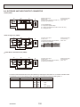
Model
Power source
Cooling capacity
(Nominal)
Temp. range of
cooling
PUMY-P112YKM(-BS)
Power input
Current input
COP
Indoor temp.
Outdoor temp.
Heating capacity
(Nominal)
Power input
Current input
COP
Temp. range of Indoor temp.
heating
Outdoor temp.
Indoor unit
Total capacity
connectable
Model / Quantity
Sound pressure level
(measured in anechoic room)
Power pressure level
(measured in anechoic room)
Refrigerant
Liquid pipe
piping diameter Gas pipe
FAN *2
Type x Quantity
Air flow rate
kW *1
kcal/h *1
BTU/h *1
kW
A
kW/kW
W.B.
D.B.
kW *2
kcal/h *2
BTU/h *2
kW
A
kW/kW
D.B.
W.B.
dB <A>
dB <A>
mm (in)
mm (in)
m3/min
L/s
cfm
Control, Driving mechanism
Motor output
kW
External static press.
Type x Quantity
Manufacture
Starting method
Capacity control %
Compressor
Motor output
Case heater
Lubricant
kW
kW
External finish
External dimension HxWxD
Protection
devices
Refrigerant
mm
in
High pressure protection
Inverter circuit (COMP./FAN)
Compressor
Fan motor
Type x original charge
Control
PUMY-P140YKM(-BS)
15 - 125 /9
PUMY-P125YKM(-BS)
3-phase380-415V, 50Hz
14.0
12,040
47,768
3.46
5.53/ 5.26/ 5.07
4.05
15 to 24 °C
-5 to 46 °C
16.0
13,760
54,592
3.74
5.98/ 5.68/ 5.48
4.28
15 to 27°C
-20 to 15°C
50 - 130% of outdoor unit capacity
15 - 140 /10
49/ 51
50/ 52
51/ 53
-
-
-
12.5
10,750
42,650
2.79
4.46/ 4.24/ 4.09
4.48
14.0
12,040
47,768
3.04
4.86/ 4.62/ 4.45
4.61
15.5
13,330
52,886
4.52
7.23/ 6.87/ 6.62
3.43
18.0
15,480
61,416
4.47
7.15/ 6.79/ 6.55
4.03
15 - 140 /12
9.52 (3/8)
15.88 (5/8)
Propeller Fan x 2
110
1,833
3,884
DC control
0.06+0.06
0
Scroll hermetic compressor x 1
Mitsubishi Electric Corporation
Inverter
Cooling 26 to 100
Cooling 24 to100
Cooling 21 to 100
Heating 20 to 100
Heating 18 to 100
Heating 17 to 100
2.9
3.5
3.9
0
FV50S(2.3litter)
Galvanized Steel Sheet
Munsell No. 3Y 7.8/1.1
1338 x 1050 x 330(+25)
52-11/16 x 41-11/32 x 13 (+1)
High pressure Switch
Overcurrent detection, Overheat detection(Heat Sink thermistor)
Compressor thermistor, Over current detection
Overheating, Voltage protection
R410A 4.8kg
Electronic Expansion Valve
Net weight
kg (lb)
Heat exchanger
HIC circuit (HIC: Heat Inter-Changer)
Defrosting method
Drawing
External
Wiring
Standard
Document
attachment
Accessory
Optional parts
125 (276)
Cross Fin and Copper tube
HIC circuit
Reversed refrigerant circuit
BK01N339
BH78B814
Installation Manual
Grounded lead wire x2
Joint: CMY-Y62-G-E
Header: CMY-Y64/68-G-E
Remarks
Indoor :
Outdoor :
Pipe length :
Level difference :
* 1 Nominal cooling conditions
* 2 Nominal heating conditions
27 °C D.B./19 °C W.B. (81 °F D.B/66 °F W.B.)
20 °C D.B. (68 °F D.B.)
7°C DB/6°C W.B. (45 °F D.B./43 °F W.B.)
35 °C D.B. (95 °F D.B.)
7.5 m (24-9/16 ft)
7.5 m (24-9/16 ft)
0 m (0 ft)
0 m (0 ft)
Note : 1. Nominal conditions * 1, * 2 are subject to ISO 15042.
2. Due to continuing improvement, above specifications may be subject to change without notice.
OCH547
8
Unit converter
kcal/h = kW × 860
BTU/h = kW × 3,412
cfm = m3/min x 35.31
lb = kg/0.4536
Above specification data is
subject to rounding variation.
DATA
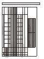
4
4-1. COOLING AND HEATING CAPACITY AND CHARACTERISTICS
4-1-1. Method for obtaining system cooling and heating capacity:
To obtain the system cooling and heating capacity and the electrical characteristics of the outdoor unit, first add up the ratings
of all the indoor units connected to the outdoor unit (see table below), and then use this total to find the standard capacity with
the help of the tables on 4-3. STANDARD CAPACITY DIAGRAM.
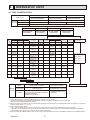
(1) Capacity of indoor unit
P•FY Series
M Series
Model Number Model 15 Model 20 Model 25 Model 32 Model 40 Model 50 Model 63 Model 71 Model 80 Model 100 Model 125 Model 140
for indoor unit
Model
Capacity
1.7
2.2
2.8
3.6
4.5
5.6
7.1
8.0
9.0
Model Number Model 15 Model 20 Model 22 Model 25 Mod 35 Model 42 Model 50 Model 60 Model 71
for indoor unit
Model
Capacity
1.5
2.0
2.2
2.5
3.5
4.2
5.0
6.0
7.1
11.2
14.0
16.0
_
_
_
_
_
_
(2) Sample calculation
1System assembled from indoor and outdoor unit (in this example the total capacity of the indoor units is greater than that of
the outdoor unit)
• Outdoor unit PUMY-P125YKM
• Indoor unit PKFY-P25VBM-E o 2 , PLFY-P50VLMD-E o 2
2According to the conditions in 1, the total capacity of the indoor unit will be: 2.8 o 2 + 5.6 o 2 = 16.8
3The following figures are obtained from the 16.8 total capacity of indoor units, referring the standard capacity diagram in "4-3-3. PUMY-P125VKM(-BS) PUMY-P125YKM(-BS) <cooling>" and "4-3-4. PUMY-P125VKM(-BS) PUMY-P125YKM(-BS) <heating>" :
Capacity (kW)
Outdoor unit power consumption (kW) Outdoor unit current (A)/400V
Cooling
Heating
Cooling
Heating
Cooling
Heating
A 14.60
B 16.33
3.51
3.44
5.34
5.23
4-1-2. Method for obtaining the heating and cooling capacity of an indoor unit:
(1) The capacity of each indoor unit (kW) = the capacity A (or B) o
model capacity
total model capacity of all indoor units
(2) Sample calculation (using the system described above in 4-1-1. (2) ):
During cooling:
During heating:
• The total model capacity of the indoor unit is:
2.8 o 2 + 5.6 o 2=16.8kW
Therefore, the capacity of PKFY-P25VBM-E and
PLFY-P50VLMD-E will be calculated as follows
by using the formula in 4-1-2. (1):
• The total model capacity of indoor unit is:
3.2 o 2 + 6.3 o 2=19.0
Therefore, the capacity of PKFY-P25VBM-E and
PLFY-P50VLMD-E will be calculated as follows by
using the formula in 4-1-2. (1):
2.8
= 2.43kW
16.8
5.6
Model 50=14.6 o
= 4.87kW
16.8
3.2
= 2.75kW
19.0
6.3
Model 50=16.33 o
= 5.41kW
19.0
Model 25=14.6 o
OCH547
Model 25=16.33 o
9
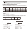
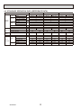
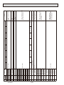
4-2. STANDARD OPERATION DATA (REFERENCE DATA)
Operation
Indoor
Ambient
DB/
temperature Outdoor
WB
No. of connected units
Unit
Indoor unit No. of units in operation
Model
—
Operating
conditions
Main pipe
Piping
Branch pipe
m
Total pipe length
Fan speed
—
Amount of refrigerant
kg
Electric current
A
Outdoor unit Voltage
V
Compressor frequency
Hz
LEV
Indoor unit
Pulse
opening
Pressure
High pressure/Low pressure
MPa
Discharge
Heat exchanger outlet
Outdoor
unit
Accumulator inlet
Temp. of
°C
each section
Compressor inlet
LEV inlet
Indoor unit
Heat exchanger inlet
OCH547
PUMY-P112VKM/YKM(-BS)
PUMY-P125VKM/YKM(-BS)
PUMY-P140VKM/YKM(-BS)
27 °C/ 19 °C
20 °C/ —
27 °C/ 19 °C
20 °C/ —
27 °C/ 19 °C
20 °C/ —
35 °C
7 °C/ 6 °C
35 °C
7 °C/ 6 °C
35 °C
7 °C/ 6 °C
2
2
50 x 1/ 63 x 1
5
2.5
10
Hi
7.2
16.17/ 5.26
17.38/ 5.67
230/ 400
67
69
2
2
63 × 2
5
2.5
10
Hi
7.2
21.67/ 7.12
21.91/ 7.22
230/ 400
84
86
2
2
63 x 1 / 80×1
5
2.5
10
Hi
7.2
25.84/ 8.58
25.54/ 8.48
230/ 400
96
96
357
421
447
525
511
586
2.70/ 0.94
67.0
40.2
8.7
10.7
18.9
12.3
2.86/ 0.70
71.9
2.0
1.0
1.3
32.4
55.5
2.86/ 0.88
69.7
40.8
8.0
9.1
17.7
11.1
2.87/ 0.67
72.1
1.3
0.2
0.1
33.0
55.7
2.95/ 0.85
70.7
43.7
5.6
7.8
17.0
10.4
2.95/ 0.65
73.2
0.9
-0.6
-0.7
33.4
56.8
10
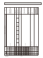
PUMY-P112YKM
PUMY-P112VKM
Cooling
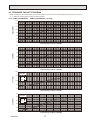
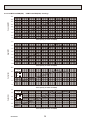
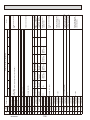
4-3. STANDARD CAPACITY DIAGRAM
Before calculating the sum of total capacity of indoor units, please convert the value into the kW model capacity following the formula on
"4-1-1. Method for obtaining system cooling and heating capacity".
4-3-1. PUMY-P112VKM(-BS)
PUMY-P112YKM(-BS) <cooling>
16.0
Capacity(kW)
14.0
12.0
10.0
8.0
6.0
4.0
2.0
2.0
4.0
6.0
8.0
4.0
6.0
8.0
6.0
8.0
6.0
8.0
10.0
12.0
14.0
16.0
18.0
20.0
10.0
12.0
14.0
16.0
18.0
20.0
10.0
12.0
14.0
16.0
18.0
20.0
10.0
12.0
14.0
16.0
18.0
20.0
Total capacity of indoor units(kW)
3.5
Input(kW)
3.0
2.5
2.0
1.5
1.0
0.5
2.0
Total capacity of indoor units(kW)
20.0
Current(A)
V-Type
15.0
220V
230V
240V
10.0
5.0
0.0
2.0
4.0
Total capacity of indoor units(kW)
6.0
Y-Type
Current(A)
5.0
380V
400V
415V
4.0
3.0
2.0
1.0
OCH547
2.0
4.0
Total capacity of indoor units(kW)
11
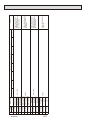
PUMY-P112YKM
PUMY-P112VKM
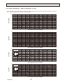
4-3-2. PUMY-P112VKM(-BS)
Heating
PUMY-P112YKM(-BS) <heating>
16.0
Capacity(kW)
14.0
12.0
10.0
8.0
6.0
4.0
2.0
2.0
4.0
6.0
8.0
4.0
6.0
8.0
6.0
8.0
6.0
8.0
10.0
12.0
14.0
16.0
18.0
200.
10.0
12.0
14.0
16.0
18.0
20.0
10.0
12.0
14.0
16.0
18.0
20.0
10.0
12.0
14.0
16.0
18.0
20.0
Total capacity of indoor units(kW)
3.5
Input(kW)
3.0
2.5
2.0
1.5
1.0
0.5
2.0
Total capacity of indoor units(kW)
20.0
Current(A)
V-Type
15.0
220V
230V
240V
10.0
5.0
0.0
2.0
4.0
Total capacity of indoor units(kW)
6.0
Y-Type
Current(A)
5.0
380V
400V
415V
4.0
3.0
2.0
1.0
2.0
OCH547
4.0
Total capacity of indoor units(kW)
12
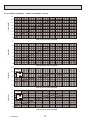
PUMY-P125YKM
PUMY-P125VKM
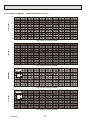
4-3-3. PUMY-P125VKM(-BS)
Cooling
PUMY-P125YKM(-BS) <cooling>
Before calculating the sum of total capacity of indoor units, please convert the value into the kW model capacity following the formula on
"4-1-1. Method for obtaining system cooling and heating capacity".
18.0
16.0
Capacity(kW)
14.0
12.0
10.0
8.0
6.0
4.0
2.0
2.0
4.0
6.0
8.0
4.0
6.0
8.0
6.0
8.0
6.0
8.0
10.0
12.0
14.0
16.0
18.0
20.0
10.0
12.0
14.0
16.0
18.0
20.0
10.0
12.0
14.0
16.0
18.0
20.0
10.0
12.0
14.0
16.0
18.0
20.0
Total capacity of indoor units(kW)
4.0
3.5
Input(kW)
3.0
2.5
2.0
1.5
1.0
0.5
2.0
Total capacity of indoor units(kW)
20.0
Current(A)
V-Type
15.0
220V
230V
240V
10.0
5.0
0.0
2.0
4.0
Total capacity of indoor units(kW)
6.0
Y-Type
Current(A)
5.0
380V
400V
415V
4.0
3.0
2.0
1.0
OCH547
2.0
4.0
Total capacity of indoor units(kW)
13
PUMY-P125YKM
PUMY-P125VKM
4-3-4. PUMY-P125VKM(-BS)
Heating
PUMY-P125YKM(-BS) <heating>
18.0
16.0
Capacity(kW)
14.0
12.0
10.0
8.0
6.0
4.0
2.0
2.0
4.0
6.0
8.0
4.0
6.0
8.0
6.0
8.0
6.0
8.0
10.0
12.0
14.0
16.0
18.0
20.0
10.0
12.0
14.0
16.0
18.0
20.0
10.0
12.0
14.0
16.0
18.0
20.0
10.0
12.0
14.0
16.0
18.0
20.0
Total capacity of indoor units(kW)
4.0
3.5
Input(kW)
3.0
2.5
2.0
1.5
1.0
0.5
2.0
Total capacity of indoor units(kW)
20.0
Current(A)
V-Type
15.0
220V
230V
240V
10.0
5.0
0.0
2.0
4.0
Total capacity of indoor units(kW)
6.0
Y-Type
Current(A)
5.0
380V
400V
415V
4.0
3.0
2.0
1.0
2.0
OCH547
4.0
Total capacity of indoor units(kW)
14
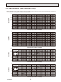
PUMY-P140YKM
PUMY-P140VKM
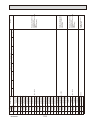
4-3-5. PUMY-P140VKM(-BS)
Cooling
PUMY-P140YKM(-BS) <cooling>
Before calculating the sum of total capacity of indoor units, please convert the value into the kW model capacity following the formula on
"4-1-1. Method for obtaining system cooling and heating capacity".
20.0
18.0
Capacity(kW)
16.0
14.0
12.0
10.0
8.0
6.0
4.0
2.0
2.0
4.0
6.0
8.0
2.0
4.0
6.0
8.0
6.0
8.0
6.0
8.0
10.0
12.0
14.0
16.0
18.0
20.0
22.0
10.0
12.0
14.0
16.0
18.0
20.0
22.0
10.0
12.0
14.0
16.0
18.0
20.0
22.0
10.0
12.0
14.0
16.0
18.0
20.0
22.0
Total capacity of indoor units(kW)
5.0
4.5
Input(kW)
4.0
3.5
3.0
2.5
2.0
1.5
1.0
0.5
Total capacity of indoor units(kW)
25.0
V-Type
Current(A)
20.0
220V
230V
240V
15.0
10.0
5.0
0.0
2.0
4.0
Total capacity of indoor units(kW)
8.0
Y-Type
Current(A)
7.0
6.0
380V
400V
415V
5.0
4.0
3.0
2.0
1.0
OCH547
2.0
4.0
Total capacity of indoor units(kW)
15
PUMY-P140YKM
PUMY-P140VKM
4-3-6. PUMY-P140VKM(-BS)
Heating
PUMY-P140YKM(-BS) <heating>
20.0
18.0
Capacity(kW)
16.0
14.0
12.0
10.0
8.0
6.0
4.0
2.0
2.0
4.0
6.0
8.0
2.0
4.0
6.0
8.0
6.0
8.0
6.0
8.0
10.0
12.0
14.0
16.0
18.0
20.0
22.0
10.0
12.0
14.0
16.0
18.0
20.0
22.0
10.0
12.0
14.0
16.0
18.0
20.0
22.0
10.0
12.0
14.0
16.0
18.0
20.0
22.0
Total capacity of indoor units(kW)
5.0
4.5
Input(kW)
4.0
3.5
3.0
2.5
2.0
1.5
1.0
0.5
Total capacity of indoor units(kW)
25.0
V-Type
Current(A)
20.0
220V
230V
240V
15.0
10.0
5.0
0.0
2.0
4.0
Total capacity of indoor units(kW)
8.0
Y-Type
Current(A)
7.0
6.0
380V
400V
415V
5.0
4.0
3.0
2.0
1.0
2.0
OCH547
4.0
Total capacity of indoor units(kW)
16
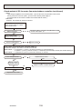
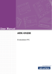
4-4. CORRECTING COOLING AND HEATING CAPACITY
4-4-1. Correcting Changes in Air Conditions
(1) The performance curve charts (Figure 1, 2) show the change ratio of capacity and input (power consumption) according to the
indoor and outdoor temperature condition when defining the rated capacity (total capacity) and rated input under the standard
condition in standard piping length (5 m) as “1.0”.
• Standard conditions:
Indoor D.B. 27 ˚C / W.B. 19 ˚C
Rated cooling capacity
Outdoor D.B. 35 ˚C
Indoor D.B. 20 ˚C
Rated heating capacity
Outdoor D.B. 7 ˚C / W.B. 6 ˚C
• Use the rated capacity and rated input given in “4-3. Standard capacity diagram”.
• The input is the single value on the side of the outdoor unit; the input on the sides of each indoor unit must be added to
obtain the total input.
(2) The capacity of each indoor unit may be obtained by multiplying the total capacity obtained in (1) by the ratio between the
individual capacity at the rated time and the total capacity at the rated time.
Individual capacity under stated conditions = total capacity under the stated conditions o
individual capacity at the rated time
total capacity at the rated time
(3) Capacity correction factor curve
PUMY-P112/125/140VKM(-BS)PUMY-P112/125/140YKM(-BS)
Figure 1
Figure 2
Heating performance curve
Cooling performance curve
1.4
1.4
Cooling
Capacity
24
22
20
1.2
(ratio)
1.0
Heating
18
Cooling
Capacity
(ratio)
0.6
INDOOR
<D.B. :>
0.8
0.6
0.4
<W.B. :>
Power
consumption 1.2
22
<D.B. :>
1.2
1.0
20
19
0.8
INDOOR
1.4
24
(ratio)
20
Heating
Power
1.0
consumption
(ratio)
18
15
25
0.8
0.6
16
0.4
0.6
INDOOR
0
10
20
30
40 46
<W.B. :>
Outdoor <D.B. :>
OCH547
25
INDOOR
16
1.4
0.2
-15 -10
20
1.0
19
0.8
15
1.2
0.4
-15
-10
-5
0
5
Outdoor <W.B. :>
17
10
15
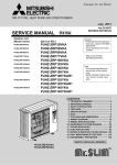
4-4-2. Correcting Capacity for Changes in the Length of Refrigerant Piping
(1) During cooling, obtain the ratio (and the equivalent piping length) of the outdoor units rated capacity and the total in-use
indoor capacity, and find the capacity ratio corresponding to the standard piping length from Figure 3. Then multiply by
the cooling capacity from Figure 1 to obtain the actual capacity.
(2) During heating, find the equivalent piping length, and find the capacity ratio corresponding to standard piping length from
Figure 3. Then multiply by the heating capacity from Figure 2 to obtain the actual capacity.
(1) Capacity Correction Curve
Figure 3
Cooling
Heating
1.00
0.95
Heating P112, 125, 140
models
Capacity ratio [%]
0.90
0.85
0.80
0.75
Cooling P112 model
0.70
Cooling P125 model
0.65
Cooling P140 model
0.60
0.55
0.50
0
20
40
60
80
100
120
140
160
200 [m]
180
Corrected pipe length
(2) Method for Obtaining the Equivalent Piping Length
Equivalent length for type P112·125·140 = (length of piping to farthest indoor unit) + (0.3 o number of bends in the piping) (m)
Length of piping to farthest indoor unit: type P112~P140.....150m
4-4-3. Correction of Heating Capacity for Frost and Defrosting
If heating capacity has been reduced due to frost formation or defrosting, multiply the capacity by the appropriate correction
factor from the following table to obtain the actual heating capacity.
Correction factor diagram
Outdoor Intake temperature (W.B.°C)
6
4
2
0
-2
-4
-6
-8
-10
-15
-20
Correction factor
1.0
0.98
0.89
0.88
0.89
0.9
0.95
0.95
0.95
0.95
0.95
OCH547
18
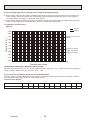
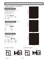
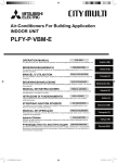
4-5. NOISE CRITERION CURVES
MODE SPL(dB)
COOLING
49
HEATING
51
90
80
70
NC-70
60
NC-60
50
NC-50
40
NC-40
30
NC-30
20
10
APPROXIMATE
THRESHOLD OF
HEARING FOR
CONTINUOUS
NOISE
63
NC-20
125
250
500
1000
2000
4000
8000
MODE SPL(dB)
COOLING
51
HEATING
53
OCTAVE BAND SOUND PRESSURE LEVEL, dB (0 dB = 0.0002 µbar)
LINE
90
80
70
NC-70
60
NC-60
50
NC-50
40
NC-40
30
NC-30
20
10
APPROXIMATE
THRESHOLD OF
HEARING FOR
CONTINUOUS
NOISE
63
125
NC-20
250
500
1000
2000
4000
8000
BAND CENTER FREQUENCIES, Hz
BAND CENTER FREQUENCIES, Hz
PUMY-P140VKM(-BS)
PUMY-P140YKM(-BS)
MODE SPL(dB)
COOLING
50
HEATING
52
PUMY-P125VKM(-BS)
PUMY-P125YKM(-BS)
OCTAVE BAND SOUND PRESSURE LEVEL, dB (0 dB = 0.0002 µbar)
OCTAVE BAND SOUND PRESSURE LEVEL, dB (0 dB = 0.0002 µbar)
PUMY-P112VKM(-BS)
PUMY-P112YKM(-BS)
LINE
LINE
90
80
70
NC-70
60
NC-60
50
MICROPHONE
NC-50
1m
40
NC-40
30
UNIT
NC-30
20
10
APPROXIMATE
THRESHOLD OF
HEARING FOR
CONTINUOUS
NOISE
63
125
1.5m
NC-20
250
500
1000
2000
4000
8000
BAND CENTER FREQUENCIES, Hz
GROUND
OCH547
19
FREE
Min. 150mm
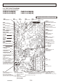
• • • Refrigerant
Min. 15mm
Service space
Min.15
Front trunking hole
(Knock-Out)
Power supply wiring hole
( 40 Knock-Out)
Front piping hole
(Knock-Out)
92
60
75
92
Power supply wiring hole
( 27 Knock-Out)
55
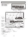
Piping Knock-Out Hole Details
GAS pipe connection (FLARE) 15.88 (5/8F)
2 • • • Refrigerant LIQUID pipe connection (FLARE) 9.52 (3/8F)
*1 • • • Indication of STOP VALVE connection location.
1
Example of Notes
Min. 1000mm
Min. 15mm
Right piping hole
(Knock-Out)
Power supply wiring hole
( 27 Knock-Out)
Handle for
moving
Min.500
92
29
75
Max.30
92
55
50
Right trunking hole
(Knock-Out)
Power supply wiring hole
( 40 Knock-Out)
Rear Air Intake
FOUNDATION
Rear trunking hole
(Knock-Out)
75
55
Handle for
moving
92
60
Side Air Intake
Rear piping hole
(Knock-Out)
92
Power supply wiring hole
( 40 Knock-Out)
Handle for
moving
Side Air Intake
Power supply wiring hole
( 27 Knock-Out)
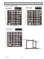
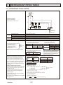
Piping and wiring connections
can be made from 4 directions:
FRONT, Right, Rear and Below.
<Foundation bolt height>
4 PIPING-WIRING DIRECTIONS
3 FOUNDATION BOLTS
Please secure the unit firmly
with 4 foundation (M10<W3/8>) bolts.
(Bolts and washers must be
purchased locally.)
2 SERVICE SPACE
Dimensions of space needed
for service access are
shown in the below diagram.
1 FREE SPACE (Around the unit)
1338
The diagram below shows a basic example.
Explantion of particular details are
given in the installation manuals etc.
3
73 60
26
55
27
Min.150
Min.500
92
27
3
73 60
26
55
27
3
73 60
26
632
369
330
25
26
154
45
136
110
225
160
362
160
160
70
Drain hole
(5- 33)
Ground for the power supply
("GR"marking position)
1050
Air Discharge
Installation Feet
56
42
81
For the
branch box
power supply
2
1
Handle for
moving
Service panel
Ground for
the branch box
power supply
Bottom piping hole
(Knock-Out)
Air Intake
For the
transmission line
For concentration
control
Rear piping cover
Front piping cover
Ground for the transmission line
Ground for concentration control
For the
power supply
Terminal connection
From left to right
56
33
0
53
2-U Shaped notched holes
(Foundation Bolt M10)
2-12×36 Oval holes
(Foundation Bolt M10)
225
417
Rear Air Intake
600
19
370
28
*1 426
20
86
OCH547
1062
PUMY-P112VKM(-BS)
PUMY-P125VKM(-BS)
PUMY-P140VKM(-BS)
*1 510
5
OUTLINES AND DIMENSIONS
Unit : mm
FREE
Min. 150mm
• • • Refrigerant
Min. 15mm
Power supply wiring hole
( 40Knock-Out)
Front trunking hole
(Knock-Out)
Front piping hole
(Knock-Out)
92
60
75
Power supply wiring hole
( 27Knock-Out)
55
Piping Knock-Out Hole Details
Handle for
moving
Min.500
Right piping hole
(Knock-Out)
Service space
Min.15
GAS pipe connection (FLARE) 15.88 (5/8F)
2 • • • Refrigerant LIQUID pipe connection (FLARE) 9.52 (3/8F)
•
•
•
Indication
of
STOP VALVE connection location.
*1
1
Example of Notes
Min. 1000mm
Min. 15mm
92
29
92
Min.150
75
92
Min.500
55
50
3 FOUNDATION BOLTS
Max.30
Power supply wiring hole
( 27Knock-Out)
Power supply wiring hole
( 40Knock-Out)
FOUNDATION
55
Rear Air Intake
<Foundation bolt height>
Please secure the unit firmly
with 4 foundation (M10<W3/8>) bolts.
(Bolts and washers must be
purchased locally.)
Right trunking hole
(Knock-Out)
3
73 60
2 SERVICE SPACE
3
73 60
26
Dimensions of space needed
for service access are
shown in the below diagram.
4 PIPING-WIRING DIRECTIONS
75
60
92
Rear piping hole
(Knock-Out)
92
Power supply wiring hole
( 27Knock-Out)
Power supply wiring hole
( 40Knock-Out)
Rear trunking hole
(Knock-Out)
Handle for
moving
Side Air Intake
Piping and wiring connections
can be made from 4 directions:
FRONT, Right, Rear and Below.
330
Handle for
moving
Side Air Intake
1338
1 FREE SPACE (Around the unit)
55
27
632
369
45
110
225
160
362
160
160
1050
Air Discharge
Installation Feet
600
56
42
81
For the
branch box
power supply
2
1
Handle for
moving
Service panel
Ground for
the branch box
power supply
Bottom piping hole
(Knock-Out)
For the
transmission line
For concentration
control
Rear piping cover
Front piping cover
Air Intake
Ground for the transmission line
Ground for concentration control
Ground for the power supply
For the
power supply
Terminal connection
From left to right
56
33
0
53
2-U Shaped notched holes
(Foundation Bolt M10)
2-12×36 Oval holes
(Foundation Bolt M10)
225
Drain hole(5- 33)
70
Rear Air Intake
417
The diagram below shows a basic example.
Explantion of particular details are
given in the installation manuals etc.
92
3
73 60
26
55
27
27
26
86
25
26
154
136
19
370
28
*1 426
21
909
OCH547
*1 510
PUMY-P112YKM(-BS)
PUMY-P125YKM(-BS)
PUMY-P140YKM(-BS)
Unit : mm
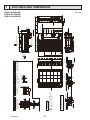
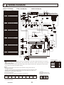
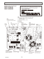
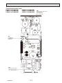
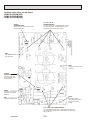
WIRING DIAGRAM
6
PUMY-P112VKM(-BS)PUMY-P125VKM(-BS) PUMY-P140VKM(-BS)
NAME
63LS 63HS TH7 TH6 TH3 TH4
TH2
t° t°
t°
MULTI. B.
CNF2
7 (WHT)
1
1 3
63LS
(BLU)
1
2
X503
3 SV2 1
(BLU)
1
21S4
M
SWU2 SWU1 SW9
3 1
5 1
5
CNLVA CNLVB
CN52C (WHT)
(RED)
(RED)
1 3
3 1
3 1
CN2
1 (RED) 7
3 SV1 1
(GRY)
LEV-B
M
is the switch position.
SW1
3 SS 1 2 CNAC
(WHT)
(RED)
2
2
4
2
BLK
2
1 2
CN4
(WHT)
TB3
7
3
1
CN2
(RED)
7
1
2
TO INDOOR UNIT
CONNECTING WIRES
DC 30V(Non-polar)
N2
CB
+
+
RED
W
TO BRANCH BOX
V
WHT
BLK
WHT
RED
B2
U
MS
3~
DCL
EI
2
3
E4
DCL2 DCL1
W V U
FUSE1
FUSE2
1
+
FOR CENTRALIZED
CONTROL
DC 30V(Non-polar)
B1
BLK
E2
t°
S
2
1
3
TH8
YLW
TB1B
IGBT
CNAC1
(WHT)
M2
-
2
NI
LI
BLK
M1 YLW
P2
BLK
1
BLK
TB7
52C
E3
WHT
CNDC
(PNK) 3
CNAC2
(RED)
RED
S
WHT
M2
P. B.
CN52C
3 (RED)
52C
2
M1 RED
MC
TB1
RED
L
BLU
N
GRN/YLW
*1 MODEL SELECTION
The black square( )indicates a switch position.
NOTES:
1.Refer to the wiring diagrams of the indoor units for details on wiring of each indoor unit.
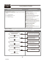
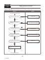
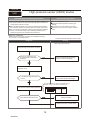
Self-diagnosis function
The indoor and outdoor units can be diagnosed automatically using the self-diagnosis switch
(SW1) and LED1, LED2 (LED indication) found on the multi-controller of the outdoor unit.
LED indication : Set all contacts of SW1 to OFF.
2. During normal operation
The LED indicates the drive state of the controller in the outdoor unit.
2
3
4
5
6
7
8
52C
21S4
SV1
(SV2)
—
—
Always lit
3. When fault requiring inspection has occurred
The LED alternately indicates the inspection code and the location of the unit in which
the fault has occurred.
OCH547
1
4
CN2
TB1 (WHT)
CN1
(WHT)
5 3 1
2
● ! WARNING: When the main supply is turned off, the voltage [340 V] in the main capacitor will drop to 20 V in approx. 2
minutes (input voltage: 230 V). When servicing, make sure that LED1, LED2 on the outdoor circuit board goes out, and then
wait for at least 1 minute.
● Components other than the outdoor board may be faulty: Check and take corrective action, referring to the service manual.
Do not replace the outdoor board without checking.
1
Compressor
operated
CN102
(WHT)
1
4
CNS1 CNS2 CN41
CN40
(RED) (YLW) (WHT) (WHT)
1 4
1
2 1 2 1 4
LED3
Cautions when Servicing
Bit
LED2
LED1
M-NET P.B.
POWER SUPPLY
~/N
230V 50Hz
Indication
SW8 SW2
SW4 SW3 SW7
2
F2
SV1
SW6
*1
1 CN51 5
(WHT)
3
SW5
CN4
(WHT)
1 2
7
F1
3 21S4 1
(GRN)
LEV-A
CN3D CN3S CN3N
(WHT) (RED) (BLU)
TRANS
3
CNDC
(PNK)
3 52C 1
(BLK)
1
1 3
63H
(YLW)
X501
MF2
MS
3~
t°
63H
1 3 1
4 1 2 2 1 1 2
63HS TH7/6 TH3 TH4 TH2
(WHT) (RED) (WHT) (WHT) (BLK)
CNF1
7 (WHT)
1
t°
X502
MF1
MS
3~
X504
Terminal Block <Power Supply>
Terminal Block <Branch Box>
Terminal Block <Comunication Line>
Terminal Block <Centralized Control Line>
Fuse <T20AL250V>
Motor For Compressor
Fan Motor
Solenoid Valve <Four-Way Valve>
High Pressure Switch
High Pressure Sensor
Low Pressure Sensor
Solenoid Valve <Bypass valve>
Thermistor <Hic Pipe>
Thermistor <Outdoor Liquid Pipe>
Thermistor <Compressor>
Thermistor <Suction Pipe>
Thermistor <Ambient>
Thermistor <Heat Sink>
Electronic Expansion Valve
Reactor
Main Smoothing Capacitor
Power Circuit Board
Connection Terminal <U/V/W-Phase>
Connection Terminal <L-Phase>
Connection Terminal <N-Phase>
Connection Terminal <DC Voltage>
Connection Terminal <DC Voltage>
Connection Terminal <Reactor>
Power Module
Connection Terminal <Ground>
Controller Circuit Board
Switch <Display Selection>
Switch <Function Selection>
Switch <Test Run>
Switch <Model Selection>
Switch <Function Selection>
Switch <Function Selection>
Switch <Function Selection>
Switch <Model Selection>
Switch <Function Selection>
Switch <Unit Address Selection, 1st digit>
Switch <Unit Address Selection, 2nd digit>
Connector <Indoor/Outdoor Transmission Line>
Connector <Centralized Control Transmission Line>
Connector <Connection For Option>
Connector <Connection For Option>
Connector <Connection For Option>
Connector <Connection For Option>
Connector <Connection For Option>
LED <Operation Inspection Display>
LED <Power Supply to Main Microcomputer>
Fuse <T6,3AL250V>
Relay
M-NET Power Circuit Board
ConnectionTerminal <Ground>
X505
SYMBOL
TB1
TB1B
TB3
TB7
FUSE1,FUSE2
MC
MF1,MF2
21S4
63H
63HS
63LS
SV1
TH2
TH3
TH4
TH6
TH7
TH8
LEV-A,LEV-B
DCL
CB
P.B.
U/V/W
LI
NI
N2
P2
DCL1,DCL2
IGBT
EI,E2,E3,E4
MULTI.B.
SW1
SW2
SW3
SW4
SW5
SW6
SW7
SW8
SW9
SWU1
SWU2
CNS1
CNS2
SS
CN3D
CN3S
CN3N
CN51
LED1,LED2
LED3
F1,F2
X501~505
M-NET P.B.
TB1
22
[ Example ]
When the compressor and
SV1 are turned during cooling
operation.
1 23 45 67 8
MODELS
SW4
PUMY-P112VKM
ON
OFF
PUMY-P125VKM
ON
OFF
PUMY-P140VKM
ON
OFF
123456
123456
123456
SW8
ON
OFF
ON
OFF
ON
OFF
12
12
12
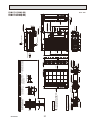
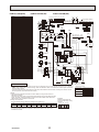
PUMY-P112YKM(-BS)PUMY-P125YKM(-BS) PUMY-P140YKM(-BS)
NAME
63LS 63HS TH7 TH6 TH3 TH4
TH2
t° t°
t°
MULTI. B.
MF2
MS
3~
CNF2
7 (WHT)
1
1 3
63LS
(BLU)
1
2
1
1 3
63H
(YLW)
X504
X503
3 SV2 1
(BLU)
21S4
LEV-B
M
M
is the switch position.
1
3 1
3 1
SWU2 SWU1 SW9
1
5 1
5
CNLVA CNLVB
(RED)
(WHT)
3
SW5
SW1
SW4 SW3 SW7
3 SV1 1
(GRY)
LED1
7
CN102
(WHT)
1
4
2
LED3
CNS1 CNS2 CN41
CN40
(RED) (YLW) (WHT) (WHT)
1 4
1
2 1 2 1 4
3 SS 1 2 CNAC
(WHT)
(RED)
SV1
2
2
4
2
M-NET P.B.
TH8
2
M1 RED
-
S
TB1B
FUSE1
B1
FUSE2
B2
U
V
MS
3~
+++
+++
W
L1
CNAC1
3 (WHT)
GRN/YLW
BLU
2
RED
LI2
LO2
WHT
LI3
LO3
BLK
CNCT
(RED) 1 2 1
LI1
WHT
L3 BLK
N
2
CNAC2
3 (RED)
LO1
1
RED
RS
TB-L1 RED
DCL
TB1
L2
POWER
SUPPLY
3N~
400V 50Hz
BLK
2
MC
TO BRANCH BOX
2
X52C RED RED
A
+
RED TB-U
WHT TB-V
BLK
TB-W
FOR CENTRALIZED
CONTROL
DC 30V(Non-polar)
WHT
1
4
CN2
TB1 (WHT)
CN1
(WHT)
5 3 1
TB-P1
+
-
YLW
TB-P3
M2
L3IN
2
M1 YLW
2
1 2 1 2 1
71 2
CN4
CN2
CN6 CN5
(WHT) (RED) (RED) (WHT)
L3OUT TB-L3
BLK
X52C
B
TO INDOOR UNIT
CONNECTING WIRES
DC 30V(Non-polar)
TB7
7
BLK
t°
TB-L2
S
2
P. B.
RED
LED2
CN4
(WHT)
1 2
F2
TB3
M2
SW6
SW8 SW2
*1
1 CN51 5
(WHT)
CN2
1 (RED) 7
F1
3 21S4 1
(GRN)
LEV-A
CN3D CN3S CN3N
(WHT) (RED) (BLU)
TRANS
3
CNDC
(PNK)
3 52C 1
(BLK)
63H
1 3 1
4 1 2 2 1 1 2
63HS TH7/6 TH3 TH4 TH2
(WHT) (RED) (WHT) (WHT) (BLK)
CNF1
7 (WHT)
1
t°
X502
MF1
MS
3~
t°
X501
Terminal Block <Power Supply>
Terminal Block <Branch Box>
Terminal Block <Comunication Line>
Terminal Block <Centralized Control Line>
Fuse <T20AL250V>
Motor For Compressor
Fan Motor
Solenoid Valve <Four-Way Valve>
High Pressure Switch
High Pressure Sensor
Low Pressure Sensor
Solenoid Valve <Bypass valve>
Thermistor <Hic Pipe>
Thermistor <Outdoor Liquid Pipe>
Thermistor <Compressor>
Thermistor <Suction Pipe>
Thermistor <Ambient>
Thermistor <Heat Sink>
Rush Current Protect Resistor
Electronic Expansion Valve
Reactor
Reactor
Power Circuit Board
Connection Terminal <U/V/W-Phase>
Connection Terminal <L1/L2/L3-Power Supply>
Connection Terminal
52C Relay
Noise Filter Circuit Board
Connection Terminal <L1/L2/L3-Power Supply>
Connection Terminal <L1/L2/L3-Power Supply>
Connection Terminal <Ground>
Controller Circuit Board
Switch <Display Selection>
Switch <Function Selection>
Switch <Test Run>
Switch <Model Selection>
Switch <Function Selection>
Switch <Function Selection>
Switch <Function Selection>
Switch <Model Selection>
Switch <Function Selection>
Switch <Unit Address Selection, 1st digit>
Switch <Unit Address Selection, 2nd digit>
Connector <Indoor/Outdoor Transmission Line>
Connector <Centralized Control Transmission Line>
Connector <Connection For Option>
Connector <Connection For Option>
Connector <Connection For Option>
Connector <Connection For Option>
Connector <Connection For Option>
LED <Operation Inspection Display>
LED <Power Supply to Main Microcomputer>
Fuse <T6,3AL250V>
Relay
M-NET Power Circuit Board
ConnectionTerminal <Ground>
X505
SYMBOL
TB1
TB1B
TB3
TB7
FUSE1,FUSE2
MC
MF1,MF2
21S4
63H
63HS
63LS
SV1
TH2
TH3
TH4
TH6
TH7
TH8
RS
LEV-A,LEV-B
ACL4
DCL
P.B.
TB-U/V/W
TB-L1/L2/L3
TB-P1/P3
X52CA/B
N.F.
LO1/LO2/LO3
LI1/LI2/LI3/NI
GD1,GD3
MULTI.B.
SW1
SW2
SW3
SW4
SW5
SW6
SW7
SW8
SW9
SWU1
SWU2
CNS1
CNS2
SS
CN3D
CN3S
CN3N
CN51
LED1,LED2
LED3
F1,F2
X501~505
M-NET P.B.
TB1
NI
+
+
U
CNDC 1
(PNK)
2
3 3
1 CNL
(BLU)
WHT
WHT
GD3
BLK
N. F.
BLK
GD1
-
ACL4
Cautions when Servicing
•
! WARNING: When the main supply is turned off, the voltage [570 V] in the main capacitor will drop to 20 V in approx. 5
minutes (input voltage: 400 V) . When servicing, make sure that LED1, LED2 on the outdoor circuit board goes out, and then
wait for at least 5 minute.
• Components other than the outdoor board may be faulty: Check and take corrective action, referring to the service manual.
Do not replace the outdoor board without checking.
NOTES:
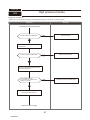
1.Refer to the wiring diagrams of the indoor units for details on wiring of each indoor unit.
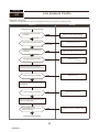
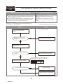
Self-diagnosis function
The indoor and outdoor units can be diagnosed automatically using the self-diagnosis switch
(SW1) and LED1, LED2 (LED indication) found on the multi-controller of the outdoor unit.
LED indication : Set all contacts of SW1 to OFF.
2.During normal operation
The LED indicates the drive state of the controller in the outdoor unit.
Bit
Indication
1
Compressor
operated
2
3
4
5
6
7
8
52C
21S4
SV1
(SV2)
—
—
Always lit
3. When fault requiring inspection has occurred
The LED alternately indicates the inspection code and the location of the unit in which
the fault has occurred.
OCH547
23
[Example]
When the compressor and
SV1 are turned during cooling
operation.
1 23 45 67 8
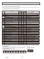
*1 MODEL SELECTION
The black square ( ) indicates a switch position.
MODELS
SW4
PUMY-P112YKM
ON
OFF
PUMY-P125YKM
ON
OFF
PUMY-P140YKM
ON
OFF
12345 6
12345 6
12345 6
SW8
ON
OFF
ON
OFF
ON
OFF
12
12
12
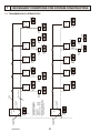
For centralized
management
78
901
056
Outdoor unit
901
For remote
controller
The address automatically become
"100" if it is set as "01~50".
3 PUMY has no 100ths digit switch.
Outdoor unit ..............051-100
Indoor unit .................001-050
Remote controller .....101-200
2 Set addresses:
connected to each refrigerant
system (outdoor and indoor).
1 A transmission wire must be
2
78
1
Remote
controller
901
901
901
1
901
901
901
901
901
901
901
Address SW
009
Indoor unit
901
Address SW
002
Indoor unit
Address SW
Remote
controller 102
Address SW
010
Indoor unit
901
Address SW
001
Indoor unit
Address SW
101
78
1
78
901
78
901
901
1
901
901
901
1
901
901
1
901
901
Address SW
007
901
901
1
901
901
Address SW
Remote 157
controller
901
Address SW
Remote
controller 154
Indoor unit
Address SW
Remote 107
controller
901
901
Address SW
004
Indoor unit
Address SW
Remote
controller 104
Address SW
008
Indoor unit
901
Address SW
003
Indoor unit
78
78
78
78
78
78
78
78
78
78
78
78
78
78
78
Transmission wire
78
78
78
78
78
78
For remote
controller
1
901
901
901
901
901
Address SW
006
Indoor unit
901
Address SW
005
Indoor unit
Address SW
Remote 105
controller
78
78
78
78
051
23
456
Outdoor unit
78
78
78
23
456
456
For centralized
management
23
456
Piping
23
456
23
456
456
23
23
456
456
24
23
23
456
456
23
23
456
23
456
456
23
23
456
456
23
23
456
456
23
23
456
456
23
23
456
23
456
456
23
23
456
456
23
23
456
23
456
23
456
23
23
456
456
23
23
456
456
23
456
456
23
23
78
78
456
23
78
78
456
23
456
OCH547
456
23
23
78
7
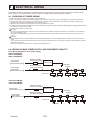
NECESSARY CONDITIONS FOR SYSTEM CONSTRUCTION
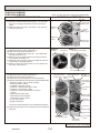
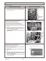
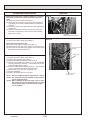
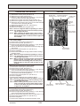
7-1. TRANSMISSION SYSTEM SETUP
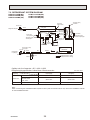
7-2. REFRIGERANT SYSTEM DIAGRAM
PUMY-P112VKM(-BS)
PUMY-P112YKM(-BS)
PUMY-P125VKM(-BS)
PUMY-P125YKM(-BS)
PUMY-P140VMK(-BS)
PUMY-P140YMK(-BS)
Thermistor (TH7)
<Ambient>
Check valve
<High pressure>
Service port
4-way valve
Strainer
Refrigerant Gas pipe
Ball valve
Solenoid
valve (SV1)
Strainer
Check valve
<Low pressure>
Strainer
High pressure
Oil separator switch (63H)
Thermistor (TH6)
<Suction pipe>
Thermistor (TH3)
<Outdoor liquid pipe>
Thermistor (TH4)
<Compressor>
Low pressure
sensor(63LS)
Accumulator
Refrigerant
Liquid pipe
Distributor
High pressure
sensor (63HS)
Capillary
tube
Thermistor (TH2)
<HIC pipe>
Stop valve
Strainer
HIC
Compressor
Thermistor (TH8)
<Heatsink>
Strainer
Strainer
LEV-1
Service port
Strainer
Refrigerant flow in cooling
Refrigerant flow in heating
LEV-2
Capillary tube for oil separator : [2.5 o [0.8 o L1000
Refrigerant piping specifications <dimensions of flared connector>
Item
Unit: mm <inch>
Liquid piping
Gas piping
P15, P20, P25, P32, P40, P50
[6.35 <1/4>
[12.7 <1/2>
Indoor unit
P63, P80, P100
P125, P140
[9.52 <3/8>
[15.88 <5/8>
Outdoor unit
P112, P125, P140
[9.52 <3/8>
[15.88 <5/8>
Capacity
Note:
When connecting the CONNECTION KIT (PAC-LV11M-J) and an M-series indoor unit, refer to the installation manual
for the CONNECTION KIT.
OCH547
25
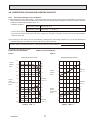
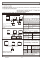
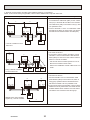
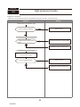
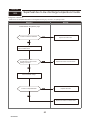
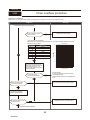
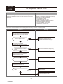
7-3. SYSTEM CONTROL
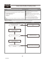
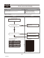
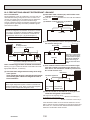
7-3-1. Example for the System
• Example for wiring control cables, wiring method and address setting, permissible lengths, and the prohibited items are listed in the standard system with detailed explanation.
The explanation for the system in this section : Use 1 single outdoor unit and multiple outdoor units for M-NET remote control
system.
Use 1 single outdoor unit and multiple indoor units in the multiple outdoor
units for the M-NET remote control system.
A. Example of a M-NET remote controller system (address setting is necessary.)
Example of wiring control cables
1. Standard operation
L1
Wiring Method and Address Setting
L2
OC
51
IC
IC
01
02
TB7
TB5
M1 M2 S
M1 M2 S
TB15
1 2
TB5
TB15
M1 M2 S
1 2
l2
L3
TB3
M1 M2 S
l1
A B
• 1 remote controller for each
indoor unit.
• There is no need for setting
the 100 position on the remote
controller.
A B
102
101
RC
RC
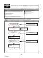
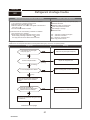
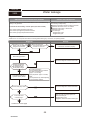
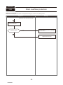
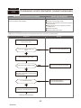
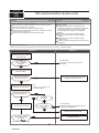
2. Operation using 2 remote controllers
OC
51
IC
IC
01
02
TB3
TB7
TB5
TB15
TB5
TB15
M1 M2 S
M1 M2 S
M1 M2 S
1 2
M1 M2 S
1 2
• Using 2 remote controllers
for each indoor unit.
A B
A B
A B
A B
101
151
102
152
RC
(Main)
RC
(Sub)
RC
(Main)
RC
(Sub)
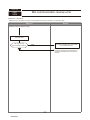
OC
IC(Main)
IC(Sub)
01
02
TB3
TB7
TB5
TB15
TB5
TB15
M1 M2 S
M1 M2 S
M1 M2 S
1 2
M1 M2 S
1 2
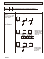
a. Same as above.
b. Same as above.
c. Set address switch (on outdoor unit P.C.B) as
shown below.
Setting Method
Range
Unit
—
Indoor Unit (IC) 001 to 050
Use the smallest
Outdoor unit
051 to 100 address of all the indoor
(OC)
units plus 50.
Indoor unit address plus
Main Remote
101 to 150
100.
Controller (RC)
Indoor unit address plus
Sub Remote
151 to 200
150.
Controller (RC)
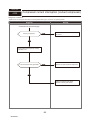
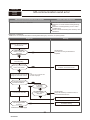
a. Same as above.
b. Connect terminals M1 and M2 on transmission cable
terminal block (TB5) of the IC main unit with the most
recent address within the same indoor unit (IC) group
to terminal block (TB6) on the remote controller.
c. Set the address setting switch (on outdoor unit P.C.B)
as shown below.
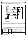
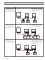
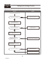
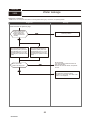
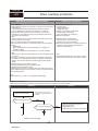
3. Group operation
51
a. Use feed wiring to connect terminals M1 and M2 on
transmission cable block (TB3) for the outdoor unit
(OC) to terminals M1 and M2 on the transmission
cable block (TB5) of each indoor unit (IC). Use nonpolarized 2 wire.
b. Connect terminals M1 and M2 on transmission cable
terminal block (TB5) for each indoor unit with the
terminal block (TB6) for the remote controller (RC).
c. Set the address setting switch (on outdoor unit P.C.B)
as shown below.
Setting Method
Unit
Range
—
Indoor unit (IC) 001 to 050
Use the smallest
Outdoor unit
051 to 100 address of all the indoor
(OC)
unit plus 50.
Indoor unit address plus
Remote
101 to 150 100.
controller (RC)
Unit
IC (Main)
Range
001 to 050
IC (Sub)
001 to 050
Outdoor Unit
Main Remote
Controller
Sub Remote
Controller
051 to 100
A B
101
RC
• Multiple indoor units operated
together by 1 remote controller
101 to 150
151 to 200
Setting Method
Use the smallest address within the
same group of indoor units.
Use an address, other than that of
the IC (Main) from among the units
within the same group of indoor
units. This must be in sequence with
the IC (Main).
Use the smallest address of all the
indoor units plus 50.
Set at an IC (Main) address within
the same group plus 100.
Set at an IC (Main) address within
the same group plus 150.
d. Use the indoor unit (IC) within the group with the
most functions as the IC (Main) unit.
Combinations of 1 through 3 above are possible.
OCH547
26
• Name, Symbol and the Maximum Remote controller Units for Connection
Name
Outdoor unit
Indoor unit
Symbol
OC
IC
M-NET remote
controller
RC
Maximum units for connection
—
1 OC unit can be connected to 1~9 (P112)/1~10 (P125)/1~12 (P140) IC units
Maximum 2 RC for 1 indoor unit, Maximum 12 RC for 1 OC
Permissible Lengths
Longest transmission cable length
(1.25 mm²)
L1 + L2, L2 + L3, L3 + L1 [ 200m
Remote controller cable length
1. If 0.5 to 1.25 mm²
R1, R2 [10m
2. If the length exceeds 10 meters,
the exceeding section should be
1.25 mm² and that section should
be a value within the total extension length of the transmission
cable and maximum transmission cable length. (L3)
Prohibited items
• M-NET remote controller (RC) and MA remote controller (MA) cannot be used together.
• Do not connect anything with TB15 of indoor unit (IC).
OC
51
IC
IC
01
02
TB3
TB7
TB5
TB15
TB5
TB15
M1 M2 S
M1 M2 S
M1 M2 S
1 2
M1 M2 S
1 2
A B
A B
TB15
101
MA
RC
Same as above
OC
51
TB3
M1 M2 S
Same as above
IC
IC
01
02
TB7
TB5
TB15
TB5
TB15
M1 M2 S
M1 M2 S
1 2
M1 M2 S
1 2
A B
A B
A B
A B
A B
101
151
102
103
104
RC
(Main)
RC
(Sub)
RC
(Main)
RC
(Sub)
RC
OC
51
IC(Main)
IC(Sub)
01
02
TB3
TB7
TB5
TB15
TB5
TB15
M1 M2 S
M1 M2 S
M1 M2 S
1 2
M1 M2 S
1 2
A B
102
RC
OCH547
• Use the indoor unit (IC)
address plus 150 as the
sub remote controller
address. In this case, it
should be 152.
• 3 or more remote controller (RC) cannot be
connected to 1 indoor
unit.
27
• The remote controller
address is the indoor
unit main address plus
100. In this case, it
should be 101.
B. Example of a group operation system with 2 or more outdoor units and a M-NET remote controller.
(Address settings are necessary.)
L1
A
C
OC
TB7
M1 M2 S M1 M2 S
L2
TB5
M1 M2 S
IC
(06)
TB5
M1 M2 S
r2
TB5
M1 M2 S
IC
(05)
r1
TB5
M1 M2 S
r3
D
A B
A B
(105)
RC
(101)
RC
L3
L4
A B
(155)
RC
E
OC
IC
(03)
(53)
L6
TB7
TB3
M1 M2 S
IC
(04)
TB5
M1 M2 S
TB5
M1 M2 S
M1 M2 S
IC
(07)
TB5
M1 M2 S
L5
Examples of Transmission Cable Wiring
IC
(02)
IC
(01)
(51)
TB3
Power Supply
Unit
r4
M1 M2 S
L7
A B
(104)
RC
System
controller
M1 M2 S
Wiring Method Address Settings
A :
B :
C :
D :
E :
( ):
B
Group
Group
Group
Shielded Wire
Sub Remote Controller
Address
a. Always use shielded wire when making connections between the outdoor unit (OC) and the indoor unit (IC), as well
for all OC-OC, and IC-IC wiring intervals.
b. Use feed wiring to connect terminals M1 and M2 and the ground terminal on the transmission cable terminal block (TB3)
of each outdoor unit (OC) to terminals M1 and M2 on the terminal S on the transmission cable block of the indoor unit
(IC).
c. Connect terminals M1 and M2 on the transmission cable terminal block of the indoor unit (IC) that has the most
recent address within the same group to the terminal block on the remote controller (RC).
d. Connect together terminals M1, M2 and terminal S on the terminal block for centralized control (TB7) for the outdoor
unit (OC).
e. DO NOT change the jumper connector CN41 on MULTI controller board.
f. The earth processing of S terminal for the centralized control terminal block (TB7) is unnecessary. Connect the terminal S on the power supply unit with the earth.
g. Set the address setting switch as follows.
Unit
IC (Main)
Range
01 to 00
IC (Sub)
01 to 50
Outdoor Unit
51 to 100
Main Remote Controller
Sub Remote Controller
MA Remote Controller
101 to 150
151 to 200
—
Setting Method
Use the smallest address within the same group of indoor units.
Use an address, other than the IC (Main) in the same group of indoor units.
This must be in sequence with the IC (Main).
Use the smallest address of all the indoor units plus 50.
The address automatically becomes “100” if it is set as “01 - 50”.
Set at an IC (Main) address within the same group plus 100.
Set at an IC (Main) address within the same group plus 150.
Unnecessary address setting (Necessary main/ sub setting)
h. The group setting operations among the multiple indoor units is done by the remote controller (RC) after the electrical
power has been turned on.
OCH547
28
Permissible Length
• Name, Symbol, and the Maximum Units for Connection
• Longest length via outdoor units : L1+L2+L3+L4, L1+L2+L3+L5, L1+L2+L6+L7 [ 500 meters (1.25mm²)
• Longest transmission cable length : L1, L3+L4, L3+L5, L6, L2+L6, L7 [ 200 meters (1.25mm²)
• Remote controller cable length : R1,R2, R2+R3, R4 [ 10 meters (0.5 to 1.25mm²)
If the length exceeds 10 meters, use a 1.25 mm² shielded wire. The length of this section (L8) should be included in the calculation of the maximum length and overall length.
A
C
OC
IC
(01)
(51)
TB3
TB7
M1 M2 S M1 M2 S
TB5
M1 M2 S
IC
(02)
TB5
M1 M2 S
IC
(05)
IC
(06)
TB5
M1 M2 S
TB5
M1 M2 S
D
A B
A B
A B
(101)
(105)
(155)
RC
RC
RC
E
OC
(53)
TB3
M1 M2 S M1 M2 S
Prohibited items
IC
(03)
TB7
TB5
M1 M2 S
IC
(04)
TB5
M1 M2 S
IC
(07)
TB5
M1 M2 S
Power Supply
Unit
M1 M2 S
A B
RC
(104)
System
controller
M1 M2 S
A :
B :
C :
D :
E :
( ):
B
Group
Group
Group
Shielded Wire
Sub Remote Controller
Address
• Never connect together the terminal blocks (TB5) for transmission wires for indoor units (IC) that have been connected to
different outdoor units (OC).
• Set all addresses to ensure that they are not overlapped.
• M-NET remote controller and MA remote controller cannot be connected with the indoor unit of the same group wiring
together.
OCH547
29
C. Example of a MA remote controller system (address setting is not necessary.)
NOTE : In the case of same group operation, need to set the address that is only main indoor unit.
Example of wiring control cables
1. Standard operation
L1
Wiring Method and Address Setting
a.Use feed wiring to connect terminals M1 and M2
on transmission cable block (TB3) for the outdoor
unit (OC) to terminals M1 and M2 on the transmission cable block (TB5) of each indoor unit (IC). Use
non-polarized 2 wire.
b.Connect terminals 1 and 2 on transmission cable
terminal block (TB15) for each indoor unit with the
terminal block for the MA remote controller (MA).
L2
OC
00
IC
IC
00
00
TB3
TB7
TB5
TB15
TB5
M1 M2 S
M1 M2 S
M1 M2 S
1 2
M1 M2 S
TB15
r1
r2
1 2
A B
• 1 remote controller for each
indoor unit.
A B
MA
MA
2. Operation using two remote controllers
a. The same as above a.
b. The same as above b.
c. In the case of using 2 remote controllers, connect
terminals 1 and 2 on transmission cable terminal
block (TB15) for each indoor unit with the terminal
block for 2 remote controllers.
· Set the sub remote controller position for one of
MA remote controller’s main switch.
Refer to the installation manual of MA remote controller.
OC
00
IC
IC
00
00
TB3
TB7
TB5
M1 M2 S
M1 M2 S
M1 M2 S
TB15
TB5
TB15
1 2
M1 M2 S
1 2
r3
r5
6
r
4
r
A B
• Using 2 remote controllers
for each indoor unit.
A B
MA
MA
A B
A B
MA
MA
3. Group operation
OC
00
IC
IC
00
00
TB7
TB5
TB15
M1 M2 S
M1 M2 S
M1 M2 S
TB5
M1 M2 S
TB15
1 2
r7
TB3
M1 M2 S
A B
• Multiple indoor units operated
together by 1 remote controller.
MA
r8
Combinations of 1 through 3 above are possible.
OCH547
30
a. The same as above a.
b. The same as above b.
c. Connect terminals 1 and 2 on transmission cable
terminal block (TB15) of each indoor unit, which is
doing group operation with the terminal block the
MA remote controller. Use non-polarized 2 wire.
d. In the case of same group operation, need to set the
address that is only main indoor unit. Please set the
smallest address within number 01-50 of the indoor
unit with the most functions in the same group.
Permissible Lengths
Prohibited items
Longest transmission cable length:
L1 + L2 [ 200m (1.25 mm²)
MA remote controller cable length:
R1, R2 [ 200m (0.3 ~ 1.25 mm²)
The MA remote controller and the
M-NET remote controller cannot be
used together with the indoor unit
of the same group.
OC
00
TB3
Longest transmission cable length:
L1 + L2 [ 200m (1.25 mm²)
MA remote controller cable length:
R3 +R4, R5 +R6 [ 200m
(0.3 ~ 1.25 mm²)
M1 M2 S
IC
00
00
TB5
TB15
TB5
TB15
M1 M2 S
1 2
M1 M2 S
1 2
TB7
M1 M2 S
IC
A B
A B
A B
RC
MA
MA
3 MA remote controller or more
cannot be connected with the
indoor unit of the same group.
OC
00
IC
IC
00
00
TB3
TB7
TB5
TB15
TB5
M1 M2 S
M1 M2 S
M1 M2 S
1 2
M1 M2 S
A B
A B
MA
MA
Longest transmission cable length:
L1 + L2 [ 200m (1.25 mm²)
MA remote controller cable length:
R7 +R8 [ 200m (0.3 ~ 1.25 mm²)
1 2
A B
A B
MA
MA
A B
MA
The second MA remote controller is
connected with the terminal block
(TB15) for the MA remote controller
of the same indoor unit (IC) as the
first remote control.
OC
00
IC
IC
00
00
TB3
TB7
TB5
TB15
TB5
TB15
M1 M2 S
M1 M2 S
M1 M2 S
1 2
M1 M2 S
1 2
A B
MA
OCH547
TB15
31
A B
MA
D. Example of a group operation with 2 or more outdoor units and a MA remote controller.
(Address settings are necessary.)
L1
C
A
OC
IC
(01)
(51)
TB3
TB7
TB5
M1 M2 S
IC
(05)
IC
(02)
TB5
TB15
M1 M2 S 1 2
TB5
M1 M2 S
D
TB5
M1 M2 S
TB15
1 2
m1
TB15
1 2
IC
(06)
m2
TB15
1 2
m4
m1
L2
A B
A B
A B
MA
MA
m3
m3
MA
L3
OC
(53)
TB3
L4
IC
TB7
M1 M2 S M1 M2 S
L6
E
(03)
IC
(04)
IC
(07)
TB15
TB5
M1 M2 S
1 2
TB5
TB15
M1 M2 S 1 2
TB15
TB5
M1 M2 S
1 2
Power Supply
Unit
m1
Examples of Transmission Cable Wiring
M1 M2 S M1 M2 S
m2
M1 M2 S
L7
A B
System
controller
MA
M1 M2 S
B
A : Group
B : Group
C : Group
D : Shielded Wire
E : Sub Remote Controller
Wiring Method Address Settings
( ): Address
a. Always use shielded wire when making connections between the outdoor unit (OC) and the indoor unit (IC), as well
for all OC-OC, and IC-IC wiring intervals.
b. Use feed wiring to connect terminals M1 and M2 and the ground terminal on the transmission cable terminal block (TB3)
of each outdoor unit (OC) to terminals M1 and M2 on the terminal S on the transmission cable block of the indoor unit (IC).
c. Connect terminals M1 and M2 on the transmission cable terminal block of the indoor unit (IC) that has the most
recent address within the same group to the terminal block on the remote controller (RC).
d. Connect together terminals M1, M2 and terminal S on the terminal block for centralized control (TB7) for the outdoor unit (OC).
e. DO NOT change the jumper connector CN41 on MULTI controller board.
f. The earth processing of S terminal for the centralized control terminal block (TB7) is unnecessary. Connect the terminal S on the power supply unit with the earth.
g. Set the address setting switch as follows.
Unit
IC (Main)
Range
01 to 00
IC (Sub)
01 to 50
Outdoor Unit
51 to 100
Main Remote Controller
Sub Remote Controller
MA Remote Controller
101 to 150
151 to 200
—
Setting Method
Use the smallest address within the same group of indoor units.
Use an address, other than the IC (Main) in the same group of indoor units.
This must be in sequence with the IC (Main).
Use the smallest address of all the indoor units plus 50.
The address automatically becomes “100” if it is set as “01 - 50”.
Set at an IC (Main) address within the same group plus 100.
Set at an IC (Main) address within the same group plus 150.
Unnecessary address setting (Necessary main/ sub setting)
h. The group setting operations among the multiple indoor units is done by the remote controller (RC) after the electrical
power has been turned on.
i. W
hen connecting PWFY unit
• For PWFY series, do not set up group connection with other indoor units.
• LOSSNAY is not available for use with PWFY series.
• Use a WMA remote controller for operation of PWFY series.
For more details, refer to the service manual for PWFY series.
OCH547
32
Permissible Length
• Name, Symbol, and the Maximum Units for Connection
Longest length via outdoor unit (M-NET cable): L1+L2+L3+L4 and L1+L2+L6+L7 [ 500 m (1.25 E more)
Longest transmission cable length (M-NET cable): L1 and L3+L4 and L6 and L2+L6 and L7 [ 200 m (1.25 E or more)
Remote controller cable length: m1 and m1+m2+m3 and m1+m2+m3+m4 [ 200 m (0.3 to 1.25 E)
C
A
OC
(51)
IC
(01)
TB3
TB7
M1 M2 S
M1 M2 S
TB5
M1 M2 S
TB15
1 2
IC
(02)
IC
(05)
IC
(06)
TB5
TB15
M1 M2 S 1 2
TB5
TB15
M1 M2 S 1 2
TB5
TB15
M1 M2 S 1 2
D
TB7
TB3
Prohibited items
A B
A B
MA
MA
MA
E
OC
(53)
M1 M2 S
A B
M1 M2 S
IC
(03)
IC
(04)
IC
(07)
TB15
TB5
M1 M2 S 1 2
TB5
TB15
M1 M2 S 1 2
TB15
TB5
M1 M2 S
1 2
Power Supply
Unit
M1 M2 S
A B
System
controller
MA
M1 M2 S
A :
B :
C :
D :
E :
( ):
B
Group
Group
Group
Shielded Wire
Sub Remote Controller
Address
• Never connect together the terminal blocks (TB5) for transmission wires for indoor units (IC) that have been connected to different outdoor units (OC).
• M-NET remote controller and MA remote controller cannot be connected with the indoor unit of the same group wiring
together.
OCH547
33
8
TROUBLESHOOTING
8-1. CHECK POINTS FOR TEST RUN
8-1-1. Procedures before test run
(1) Before a test run, make sure that the following work is completed.
• Installation related :
Make sure that the panel of cassette type and electrical wiring are done.
Otherwise electrical functions like auto vane will not operate normally.
• Piping related :
Perform leakage test of refrigerant and drain piping.
Make sure that all joints are perfectly insulated.
Check stop valves on both liquid and gas side for full open.
• Electrical wiring related :
Check ground wire, transmission cable, remote controller cable, and power supply cable for secure connection.
Make sure that all switch settings of address or adjustments for special specification systems are correctly settled.
(2) Safety check :
With the insulation tester of 500V, inspect the insulation resistance.
Do not touch the transmission cable and remote controller cable with the tester.
The resistance should be over 1.0 M". Do not proceed inspection if the resistance is under 1.0 M".
Inspect between the outdoor unit power supply terminal block and ground first, metallic parts like refrigerant pipes or the
electrical box next, then inspect all electrical wiring of outdoor unit, indoor unit, and all linked equipment .
(3) Before operation :
a) Turn the power supply switch of the outdoor unit to on for compressor protection. For a test run, wait at least 12 hours
from this point.
b) Register control systems into remote controller(s). Never touch the on/off switch of the remote controller(s). Refer
to “ 8-1-2. Special Function Operation and Settings (for M-NET Remote Controller)” as for settings. In MA remote
controller(s), this registration is unnecessary.
(4) More than 12 hours later from power supply to the outdoor unit, turn all power switch to on for the test run. Perform test run
according to the “Operation procedure” table of the bottom of this page. While test running, make test run reports .
8-1-1-1. Test run for M-NET Remote controller
When you deliver the unit after the test run, instruct the end user for proper usage of the system using owners’ manual
and the test run report you made to certificate normal operation. If abnormalities are detected during test run, refer to “8-13 Countermeasures for Error During Test Run”. As for DIP switch setting of outdoor unit, refer to “8-5. INTERNAL SWITCH
FUNCTION TABLE”.
(M-NET Remote controller)
Check code indicator (see NOTE 1)
Test run remaining time indicator (see NOTE 3)
Indoor unit liquid pipe temperature indicator
(see NOTE 4)
TEST RUN indicator
1Hr.
°C
Display panel
TEST RUN
(Cooling/Heating)
OPERATION
SWITCH button
3,4
TEMP.
ON/OFF LED (Lights up in operation)
ON/OFF button 9
ON/OFF
FILTER
AIR DIRECTION button 6
CHECK TEST
TEST RUN button 2
TIMER SET
LOUVER button 6
Control panel
FAN SPEED button 5
Operation procedure
1
2
3
4
5
6
7
8
9
Turn on the main power supply of all units at least 12 hours before test run. ”HO” appears on display panel for 3 min.
12 hours later, press TEST RUN button twice to perform test run. “TEST RUN “ appears on display panel.
Press OPERATION SWITCH button to make sure that air blows out.
Select Cooling (or Heating) by OPERATION SWITCH button to make sure that cool (or warm) air blows out.
Press Fan speed button to make sure that fan speed is changed by the button.
Press AIR DIRECTION button or LOUVER button to make sure that air direction is adjustable (horizontal, downward, upward, and each angle).
Check outdoor fans for normal operation.
Check interlocked devices (like ventilator) for normal operation, if any. This is the end of test run operation.
Press ON/OFF button to stop and cancel test run.
Notes:
1. If error code appears on remote controller or remote controller malfunctions, refer to “ 8-1-3 Countermeasures for Error During Run”.
2. During test run operation, 2-hour off timer activates automatically and remaining time is on remote controller and test run stops 2 hours later.
3. During test run, the indoor liquid pipe temperature is displayed on remote controller instead of room temperature.
4. Depending on a model, “This function is not available” appears when air direction button is pressed. However, this is not malfunction.
OCH547
34
8-1-1-2. Test run for wired remote controller <PAR-31MAA>
MENU RETURN SELECT
ON/OFF
Function buttons
F1
1 Select "Service" from the Main menu, and press the
button.
Select "Test run" with the F1 or F2 button, and press the
F3
F4
Service menu
button.
Test run
Input maintenance info.
Function setting
Check
Self check
Main menu:
Cursor
F1
2 Select "Test run" with the F1 or F2 button, and press the
F2
button.
F2
F3
F4
Test run menu
Test run
Drain pump test run
Service menu:
Cursor
F1
Test run operation
Test run
Press the F1 button to go through the operation modes in the order of
"Cool and Heat".
Cool mode: Check the cold air blow off.
Heat mode: Check the heat blow off.
F3
F4
Remain
Pipe
Cool
Switch disp.
Mode
F1
Press the
F2
Auto
Fan
F2
F3
F4
button and open the Vane setting screen.
Auto vane check*
Remain
Check the auto vane with the F1 F2 buttons.
Check the operation of the outdoor unit fan, also.
Press the
button to return to “Test run operation”.
Press the
button.
Vane
F1
When the test run is completed, the “Test run menu” screen will appear.
The test run will automatically stop after two hours.
*The function is available only for the model with vanes.
OCH547
35
F2
F3
F4
8-1-2. Special Function Operation and Settings (for M-NET Remote Controller)
• It is necessary to perform “group settings” and “paired settings” at making group settings of different refrigerant systems
(multiple outdoor unit).
(A) Group settings: Enter the indoor unit controlled by the remote controller, check the content of entries, and clear entries,
etc.
(B) Paired settings: Used to set the linked operation of a Lossnay unit.
(1) Entering address: Follow the steps below to enter the addresses of the indoor unit using the remote controller.
a) Group settings
• Turning off the remote controller: Press the ON/OFF button to stop operation (the indicator light will go off).
• Changing to indoor unit address display mode: If the FILTER and k buttons on the remote controller are pressed simultaneously and held for 2 seconds, the display shown in Figure 1 will appear.
• Changing address: Press the temperature adjustment
buttons to change the displayed address to the address to
be entered.
• Entering the displayed address: Press the TEST RUN button to enter the indoor unit with the displayed address.
The type of the unit will be displayed as shown in Figure 2 if entry is completed normally.
If a selected indoor unit does not exist, an error signal will be displayed as shown in Figure 3. When this happens, check
whether the indoor unit actually exists and perform entry again.
• Returning to the normal mode after completing entry: Press the FILTER and k buttons simultaneously and hold for 2
seconds to return to the normal mode.
Figure 1. (A) Group setting display
Figure 2. Normal completion of entry
Type of unit is displayed.
Figure 3. Entry error signal
Flashing “88” indicates entry error.
b) Paired Settings
• Turn off the remote controller: Press the remote controller’s ON/OFF button to turn it off (the indicator light will go off).
• Put in indoor unit address display mode: Press the FILTER and k buttons on the remote controller simultaneously and
hold for 2 seconds.
Note: The above steps are the same as when making group settings (A).
• Changing to the linked operation unit address display state: The display shown in Figure 4 will appear when the a
button on the remote control is pressed.
• Displaying the address of the Lossnay unit and linked indoor unit: In this situation, the indoor unit number will be the lowest
address of the group. The Lossnay unit will not operate if this setting is incorrect.
Notes:
buttons are pressed, the address may be changed to the indoor unit that are to
1.If the temperature adjustment
be linked.
buttons are pressed, the address of the linked units may be changed to the address where it
2.If the time setting
is desired to enter the Lossnay.
• Linking the Lossnay and the indoor unit: The display shown in Figure 5 will appear when the TEST RUN button is pressed.
The indoor unit whose address is displayed and the Lossnay unit with a linked address will operate in a linked manner.
Notes:
1. If it is desired to display the address of the Lossnay in the indoor unit address, display the indoor unit address in the
linked unit address, and the above content will also be recorded.
2. Apart from the indoor unit with the lowest address in the group, display and enter the addresses of the other indoor unit
that are to be linked with the Lossnay unit.
• Returning to the normal mode after completing entry: Press the FILTER and k buttons on the remote controller simultaneously and hold for 2 seconds to return to the normal mode.
Figure 4. (B) Making paired settings
The addresses of indoor
unit and linked units are
displayed simultaneously.
OCH547
Figure 5. Completing normal entry
(alternating
display)
36
These alternating IC or LC displays will appear
when entry is completed normally.
A flashing “88” will appear if there is a
problem with the entry (indicating that the
unit does not exist).
(2) Address check: Refer to section (1) regarding address entry.
a) In making group settings:
• Turn off the remote controller: Press the remote controller's ON/OFF button to stop operation (the indicator light will go off).
• Locate the indoor unit address display mode: Press the FILTER and k buttons on the remote controller simultaneously
and hold for 2 seconds.
• Display indoor unit address: The entered indoor units address and type will be displayed each time the button is pressed.
* When 1 entry is made, only 1 address will be displayed no matter how many times the w button is pressed.
• Returning to the normal mode after completing check: Simultaneously press the FILTER and k buttons on the remote
controller and hold for 2 seconds to return to the normal mode.
b) In making paired settings:
• Turn off the remote controller: Press the remote controller's ON/OFF button to stop operation (the indicator light will go off).
• Put in indoor unit address display mode: Press the FILTER and k buttons on the remote controller simultaneously and
hold for 2 seconds.
• Changing to the linked operation unit address display state: Press the a button on the remote control.
• Displaying the address of the indoor unit to be checked: Change the address to that of the indoor unit to be checked by
pressing the temperature adjustment buttons
.
• Displaying the address of the linked Lossnay unit: Press the w button to display the addresses of the linked Lossnay and
indoor unit in alternation.
• Displaying the addresses of other entered units: The addresses of the other entered units will be displayed in alternating
fashion after resting the w button again.
• Returning to the normal mode after completing the check: Simultaneously press the FILTER and k buttons on the
remote controller and hold for 2 seconds to return to the normal mode.
(3) Clearing an address: Refer to section (1) regarding the address entry and section (2) regarding checking addresses.
a) In making group settings:
• Turn off the remote controller: The procedure is same as a) in (2) Address check.
• Put in the indoor unit address display mode: The procedure is same as a) in (2) Address check.
• Displaying the indoor unit address to be cleared: The procedure is same as a) in (2) Address check.
• Clearing indoor unit address : Pressing the q button on the remote controller twice will clear the address entry of the displayed indoor unit, resulting in the display shown in Figure 6.
The display shown in Figure 7 will appear if an abnormality occurs and the entry is not cleared.
Please repeat the clearing procedure.
• Returning to the normal mode after clearing an address: The procedure is same as a) in (2) Address check.
Figure 7. Display when an abnormality has
Figure 6. Display after address has been
occurred during clearing
cleared normally
"--" will appear in the room temperature
display location.
"88" will appear in the room temperature display location.
b) In making paired settings:
• Turn off the remote controller: The procedure is same as b) in (2) Address check.
• Put into the indoor unit address display mode: The procedure is same as b) in (2) Address check.
• Put into the linked unit address display mode: The procedure is same as b) in (2) Address check.
• Display the address of the Lossnay unit or the indoor unit to be cleared.
• Deleting the address of a linked indoor unit: Pressing the q button on the remote controller twice will clear the address
entry of the displayed indoor unit, resulting in the display shown in Figure 8.
• Returning to the normal mode after clearing an address: The procedure is same as b) in (2) Address check.
Figure 8. Display after address has been cleared normally
(alternating
display)
OCH547
"--" will appear in the unit type display location when an address has
been cleared normally.
"88" will appear in the unit type display location when an abnormality
has occurred during clearing.
37
8-1-3. Countermeasures for Error During Test Run
• If a problem occurs during test run, a code number will appear on the remote controller (or LED on the outdoor unit), and the
air conditioning system will automatically cease operating.
Determine the nature of the abnormality and apply corrective measures.
Check
code
Detected Unit
Trouble
Indoor
0403
Serial communication error
1102
1300
1302
1500
Compressor temperature
Low pressure
High pressure
Superheat due to low discharge temperature
Refrigerant shortage
Blocked valve in cooling mode
4-way valve trouble in heating mode
Water leakage
Drain over flow protection
Drain sensor abnormality
Compressor current interruption (locked compressor)
Compressor overcurrent interruption
Voltage shortage/overvoltage/PAM error/L1open phase/power synchronization
signal error
Heat Sink temperature
Power module
Rotational frequency of outdoor fan motor
Air inlet thermistor trouble (TH21) or
Compressor temperature thermistor (TH4) open/short
Liquid pipe temperature thermistor trouble (TH22)
Suction pipe temperature thermistor (TH6) open/short
Gas pipe temperature thermistor trouble (TH23)
Outdoor liquid pipe temperature thermistor (TH3) open/short
Ambient thermistor (TH7) open/short
HIC pipe temperature thermistor (TH2) open/short
Heat Sink temperature thermistor (TH8) open/short
High pressure sensor (63HS)
Low pressure sensor (63LS)
Primary current
Contact failure of drain float switch
Duplex address error
Transmission processor hardware error
Transmission bus BUSY error
Signal communication error with transmission processor
No ACK error
No response frame error
MA communication receive error (no receive signal)
MA communication send error
MA communication send error
MA communication receive error
Total capacity error
Capacity code error
Connecting excessive number of units
Address setting error
1501
1508
2500
2502
2503
4100
4210
4220
4230
4250
4400
5101
5102
5103
5105
5106
5109
5110
5201
5202
5300
5701
6600
6602
6603
6606
6607
6608
6831
6832
6833
6834
7100
7101
7102
7105
Outdoor
Remote
Controller
Remarks
Outdoor unit Multi controller board ~
Power board communication trouble
Check delay code 1202
Check delay code 1402
Check delay code 1600
Check delay code 1601
Check delay code 1501
Check delay code 1608
Check delay code 4350
Check delay code 4320
Check delay code 4330
Check delay code 4350
Check delay code 4500
Check delay code 1202
Check delay code 1211
Check delay code 1205
Check delay code 1221
Check delay code 1222
Check delay code 1214
Check delay code 1402
Check delay code 1400
Check delay code 4310
Only M-NET Remote controller is detected.
Only M-NET Remote controller is detected.
Only M-NET Remote controller is detected.
Only M-NET Remote controller is detected.
Only M-NET Remote controller is detected. *
Only M-NET Remote controller is detected. *
Only MA Remote controller is detected.
Only MA Remote controller is detected.
Only MA Remote controller is detected.
Only MA Remote controller is detected.
Note:
When the outdoor unit detects No ACK error/No response error, an object indoor unit is treated as a stop, and not assumed to be abnormal.
*Abnormality for PWFY series
Self-diagnosis function
[Example]
The indoor and outdoor units can be diagnosed automatically using the self-diagnosis switch
When the compressor and
(SW1) and LED1, LED2 (LED indication) found on the multi-controller of the outdoor unit.
SV1 are turned during cooling
LED indication : Set all contacts of SW1 to OFF.
operation.
During normal operation
1 23 45 67 8
The LED indicates the drive state of the controller in the outdoor unit.
1
Bit
Indication Compressor
operated
2
3
4
5
6
7
8
52C
21S4
SV1
(SV2)
—
—
Always lit
OCH547
38
Check code
Serial communication error
0403
Abnormal points and detection methods
Abnormal if serial communication between the outdoor controller board
and outdoor power board is defective.
Causes and check points
Wire breakage or contact failure of connector CN2 or
CN4
Malfunction of power board communication circuit on
outdoor controller board
Malfunction of communication circuit on outdoor
power board
●Diagnosis of defectives
Make sure to turn the power OFF before connecting/disconnecting any connectors, or replacing boards.
Diagnosis
Remedy
Check the connection of the communication
line (CN2 and CN4) between the outdoor
controller board and power board.
Are they connected normally?
No
Yes
The communication circuit of either the
outdoor controller board or power board is
defective.
If unable to identify the defective circuit;
Replace the outdoor controller board if it
doesn't recover,
Replace the outdoor power board
39
OCH547
Connect the CN2 and CN4 properly.
Replace them in case of a breakage.
Check code
Compressor temperature trouble
1102
Chart 1 of 2
Abnormal points and detection methods
Causes and check points
(1) Abnormal if TH4 falls into following temperature conditions;
●exceeds 110 [230 °F]continuously for 5 minutes
●exceeds 125 [257 °F]
(2) Abnormal if a pressure detected by the high-pressure sensor and
converted to saturation temperature exceeds 40 [104 °F]during
defrosting, and TH4 exceeds 110 [230 °F].
TH4: Thermistor <Compressor>
LEV: Electronic expansion valve
Malfunction of stop valve
Over-heated compressor operation caused by
shortage of refrigerant
Defective thermistor
Defective outdoor controller board
LEV performance failure
Defective indoor controller board
Clogged refrigerant system caused by foreign
object
Refrigerant shortage while in heating operation
(Refrigerant liquid accumulation in compressor while
indoor unit is OFF/thermo-OFF.)
●Diagnosis of defectives
Make sure to turn the power OFF before connecting/disconnecting any connectors, or replacing boards.
Diagnosis
Is 5101 displayed when restart?
No
Remedy
Yes
(5101)
Refer to the diagnosis of check code 5101.
(1102)
Is the outdoor stop valve (liquid/
gas) fully open?
No
Open the stop valve (liquid/ gas) fully.
Yes
Repair the refrigerant leakage.
Yes
Connect the connector properly
(Repair or replace it in case of a breakage).
Yes
Is there a refrigerant leak?
No
(no leak)
Check the connection for thermistor wiring
and indoor controller board connector
Is there any abnormality on
connectors/wires such as a disconnection,
half-disconnection or breakage?
No
Continue to the next page
40
OCH547
Check code
Compressor temperature trouble
1102
Chart 2 of 2
●Diagnosis of defectives
Make sure to turn the power OFF before connecting/disconnecting any connectors, or replacing boards.
Diagnosis
Remedy
Continued from the previous page
Disconnect the thermistor wiring to check
the resistance.
Is there a resistance detected?
No
Replace the thermistor.
No
Replace the outdoor controller board.
No
Replace the indoor LEV.
Yes
Check the voltage and appearance of the
outdoor controller board.
Is the voltage normal value?
Is it free from any trace of overheating or burning?
Yes
Disconnect the indoor LEV wiring and
check the resistance.
Is there a resistance detected?
Yes
Replace the indoor controller board.
41
OCH547
Check code
Low pressure trouble
1300
Chart 1 of 3
Abnormal points and detection methods
<63L equipped model>
(1) Low pressure (63L is in operation)
Abnormal if 63L operates (under-0.03MPa) during compressor
operation.
63L
LEV
SV1
TH7
:Low pressure switch
:Electronic expansion valve
:Solenoid valve
:Thermistor <Ambient>
Causes and check points
Defective operation of stop valve (not fully open)
Clogged or broken pipe.
Malfunction or locked outdoor fan motor
Short-cycle of outdoor unit
Dirt of outdoor heat exchanger
Remote controller transmitting error caused by noise interference
Contact failure of outdoor controller board connector
Defective outdoor controller board
Short-cycle of indoor unit
Decreased airflow, clogged filter, or dirt on indoor unit.
Malfunction or locked indoor fan motor.
Decreased airflow caused by defective inspection
of outdoor temperature thermistor (It detects lower
temperature than actual temperature.)
Indoor LEV performance failure
Malfunction of fan driving circuit
SV1 performance failure
Defective low-pressure sensor
Malfunction of low-pressure sensor input circuit on
outdoor controller board
●Diagnosis of defectives
Make sure to turn the power OFF before connecting/disconnecting any connectors, or replacing boards.
Diagnosis
Is the outdoor stop valve
(liquid/ gas) fully open ?
Remedy
No
Open the stop valve (liquid/ gas) fully.
Yes
Does the outdoor fan rotare
while the operation?
No
Check the outdoor fan motor
Refer to "How to check the parts" on
outdoor unit service manual.
No
Check the indoor fan motor
Refer to "How to check the parts" on
indoor unit service manual.
Yes
Does the indoor fan rotate while
the operation?
Yes
Is the indoor unit short-cycled?
No
Yes
(filter clogged)
(no clog)
Continue to the next page
42
OCH547
Solve the short-cycle.
(no short-cycle)
Is the indoor unit filter clogged?
No
Yes
(short-cycled)
Clean the filter.
Check code
Low pressure trouble
1300
Chart 2 of 3
●Diagnosis of defectives
Make sure to turn the power OFF before connecting/disconnecting any connectors, or replacing boards.
Diagnosis
Remedy
Continued from the previous page
Is there dirt on the indoor heat
exchanger?
No
Yes
(dirty)
(no dirt)
Is the outdoor unit short-cycled?
Yes
(short-cycled)
No
Solve the short-cycle.
(no short-cycle)
Is there dirt on the outdoor heat
exchanger?
No
Wash the indoor heat exchanger.
Yes
(dirty)
Wash the outdoor heat exchanger.
(no dirt)
Are pipes clogged or broken?
Yes
Defective pipes.
No
Replace the TH7.
No
Replace the indoor LEV.
No
Replace the indoor controller board.
No
No
Disconnect the outdoor temperature
thermistor wiring and check the resistance.
Is there a resistance detected?
Yes
Disconnect the indoor LEV wiring to check
the resistance.
Is there a resistance detected?
Yes
Check the voltage and appearance of the
outdoor controller board.
Is the voltage normal?
Is it free from any trace of overheating or burning?
Yes
Continue to the next page
43
OCH547
Check code
Low pressure trouble
1300
Chart 3 of 3
●Diagnosis of defectives
Make sure to turn the power OFF before connecting/disconnecting any connectors, or replacing boards.
Diagnosis
Remedy
Continued from the previous page
Check the resistance of SV1.
Is there a resistance detected?
No
Replace the SV1.
Yes
Reconnect the connector or connect it tightly.
Yes
<63L equipped model>
Is the connector for outdoor
controller board 63L disconnected or
loose?
No
Replace the outdoor controller board.
44
OCH547
Check code
High pressure trouble
1302
Chart 1 of 4
Abnormal points and detection methods
<63H equipped model (63HS non-equipped)>
(1) High pressure abnormality (63H operation)
Abnormal if 63H operates(*) during compressor operation. (* 4.15MPa)
<63HS equipped model (63H non-equipped)>
(2) High pressure abnormality (63HS detected)
Abnormal if a pressure detected by 63HS exceeds 4.15MPa during
compressor operation.
63H : High-pressure switch
63HS: High-pressure sensor
LEV : Electronic expansion valve
SV1 : Solenoid valve
TH7 : Thermistor <Ambient>
Causes and check points
Defective operation of stop valve (not fully open)
Clogged or broken pipe.
Malfunction or locked outdoor fan motor
Short-cycle of outdoor unit
Dirt of outdoor heat exchanger
Remote controller transmitting error caused by noise interference
Contact failure of the outdoor controller board connector
Defective outdoor controller board
Short-cycle of indoor unit
Decreased airflow, clogged filter, or dirt on indoor unit.
Malfunction or locked indoor fan motor.
Decreased airflow caused by defective inspection
of outdoor temperature thermistor (It detects lower
temperature than actual temperature.)
Indoor LEV performance failure
Malfunction of fan driving circuit
SV1 performance failure
Defective high-pressure sensor
Defective high-pressure sensor input circuit on
outdoor controller board
●Diagnosis of defectives
Make sure to turn the power OFF before connecting/disconnecting any connectors, or replacing boards.
Diagnosis
Is 5201 displayed when restart?
Remedy
Yes
(5201)
Refer to the diagnosis of check code 5201.
No (1302)
Is the outdoor stop valve (liquid/
gas) fully open ?
No
Open the stop valve (liquid/ gas) fully.
No
Check the outdoor fan motor
Refer to "How to check the parts" on the
outdoor unit service manual.
No
Check the indoor fan motor
Refer to "How to check the parts" on the
indoor unit servive manual.
Yes
Does the outdoor fan rotate while
the operation?
Yes
Does the indoor fan rotate while
the operation?
Yes
Is the indoor unit short-cycled?
No
Yes
(short-cycled)
(no short-cycle)
Continue to the next page
45
OCH547
Solve the short-cycle.
Check code
High pressure trouble
1302
Chart 2 of 4
●Diagnosis of defectives
Make sure to turn the power OFF before connecting/disconnecting any connectors, or replacing boards.
Diagnosis
Remedy
Continued from the previous page
Is the indoor unit filter clogged?
No
Yes
(Clogged filter)
(No clog)
Is there dirt on the indoor heat
exchanger?
No
Clean the filter.
Yes
Wash the indoor heat exchanger.
(dirty)
(no dirt)
Yes
Is the outdoor unit short-cycled?
Solve the short cycle.
(short-cycled)
No
(no short-cycle)
Is there dirt on the outdoor heat
exchanger?
No
Yes
(no dirt)
Are the pipes clogged or broken?
Yes
No
Disconnect the TH7 wiring and check the
resistance.
Continue to the next page
46
OCH547
Wash the outdoor heat exchanger.
(dirty)
Defective pipes.
Check code
High pressure trouble
1302
Chart 3 of 4
●Diagnosis of defectives
Make sure to turn the power OFF before connecting/disconnecting any connectors, or replacing boards.
Diagnosis
Remedy
Continued from the previous page
Is there a resistance detected?
No
Replace the TH7.
No
Replace the indoor LEV.
Yes
Disconnect the indoor LEV wiring to check
the resistance.
Is there a resistance detected?
Yes
Check the voltage and appearance of the
indoor controller board.
Is the voltage normal?
Is it free from any trace of overheating or burning?
No
Yes
Check the resistance of SV1.
Continue to the next page
47
OCH547
Replace the indoor controller board.
Check code
High pressure trouble
1302
Chart 4 of 4
●Diagnosis of defectives
Make sure to turn the power OFF before connecting/disconnecting any connectors, or replacing boards.
Diagnosis
Remedy
Continued from the previous page
Is there a resistance detected?
No
Replace the SV1.
Yes
Reconnect the connector or connect it tightly.
Yes
<63H equipped model (63HS non-equipped)>
Is the connector for outdoor
controller board 63H disconnected or
loose?
No
Replace the outdoor controller board.
<63HS equipped model (63H non-equipped)>
Check the 63HS voltage.
Is there a voltage detected?
No
Replace the 63HS.
Yes
Replace the outdoor controller board.
48
OCH547
Check code
Superheat due to low discharge temperature trouble
1500
Chart 1 of 2
Abnormal points and detection methods
Abnormal if the discharge superheat is continuously detected less than
or equal to −15 [5 °F]* for 5 minutes even though the indoor LEV has
minimum open pulse after the compressor starts operating for 10 minutes.
LEV : Electronic expansion valve
TH4 : Thermistor <Compressor>
63HS: High-pressure sensor
Causes and check points
Disconnection or loose connection of TH4
Defective holder of TH4
Disconnection of LEV coil
Disconnection of LEV connector
LEV performance failure
*At this temperature, conditions for the abnormality detection will not be
satisfied if no abnormality is detected on either TH4 or 63HS.
●Diagnosis of defectives
Make sure to turn the power OFF before connecting/disconnecting any connectors, or replacing boards.
Diagnosis
Is the TH4 wiring disconnected?
No
Remedy
Connect the wiring properly.
Yes
(disconnected)
(connected properly)
Check the resistance of TH4
Is the resistance normal ?
0 ···700k" 10 ···410k"
20 ···250k" 30 ···160k"
40 ···104k"
No
Replace the TH4.
Yes
Check the connector contact and wiring of
the indoor LEV.
Is there any abnormality
such as a half-disconnection or
breakage?
Yes
No
Disconnect the indoor LEV wiring to check
the resistance.
Continue to the next page
49
OCH547
Connect the connector properly,
or replace the LEV.
Check code
Superheat due to low discharge temperature trouble
1500
Chart 2 of 2
●Diagnosis of defectives
Make sure to turn the power OFF before connecting/disconnecting any connectors, or replacing boards.
Diagnosis
Remedy
Continued from the previous page
Is there a resistance detected?
No
Replace the indoor LEV.
No
Replace the indoor controller board.
No
Replace the 63HS.
Yes
Check the voltage and appearance of the
indoor controller board.
Is the voltage normal ?
Is it free from any trace of overheating or burning?
Yes
Check the 63HS voltage.
Is there a voltage detected?
Yes
Replace the outdoor controller board.
50
OCH547
Check code
Refrigerant shortage trouble
1501
Chart 1 of 2
Abnormal points and detection methods
(1) Abnormal when all of the following conditions are satisfied:
1. The compressor is operating in HEAT mode
2.Discharge super heat is 80 or more.
3.Difference between TH7 and the TH3 applies to the formula of
(TH7-TH3 < 5 )
4.The 63HS detects below 2.04 MPa.
(2) Abnormal when all of the following conditions are satisfied:
1.The compressor is in operation
2.When cooling, discharge superheat is 80 or more
When heating, discharge superheat is 90 or more.
The High-pressure sensor detects below 2.32 MPa
Causes and check points
Defective operation of stop valve (not fully open)
Defective thermistor
Defective outdoor controller board
Indoor LEV performance failure
Gas leakage or shortage
Defective 63HS
TH3 : Thermistor <Outdoor liquid pipe>
TH7 : Thermistor <Ambient>
LEV : Electronic expansion valve
63HS: High-pressure sensor
●Diagnosis of defectives
Make sure to turn the power OFF before connecting/disconnecting any connectors, or replacing boards.
Diagnosis
Is the outdoor stop valve (ball
valve) fully open ?
Remedy
No
Open the stop valve (ball balve) fully.
Yes
Repair the refrigerant leak.
Yes
Is there a refrigerant leak?
No
(leaking)
(no leaking)
Is 5104 displayed when restart?
Yes
Refer to the diagnosis of check code 5104.
Yes
Connect the connector properly.
(Repair or replace it in case of a breakage.)
(5104)
No
(1501)
Check relevant thermistor wirings and
connector contacts of the controller
boards.
Is there any abnormality on
connectors such as a disconnection,
half-disconnection or breakage?
No
Disconnect the thermistor wiring and check
the resistance.
Continue to the next page
51
OCH547
Check code
Refrigerant shortage trouble
1501
Chart 2 of 2
●Diagnosis of defectives
Make sure to turn the power OFF before connecting/disconnecting any connectors, or replacing boards.
Diagnosis
Remedy
Continued from the previous page
Is there a resistance detected?
No
Replace the thermistor.
No
Replace the 63HS.
No
Replace the outdoor controller board.
No
Replace the indoor LEV.
Yes
Check the 63HS voltage.
Is there a voltage detected?
Yes
Check the voltage and appearance of the
outdoor controller board.
Yes
Is the voltage normal value?
Is it free from any trace of overheating or burning?
Yes
Disconnect the indoor LEV wiring and
check the resistance.
Is there a resistance detected?
Yes
Replace the indoor controller board.
52
OCH547
Check code
Blocked valve in cooling mode
1501
Abnormal points and detection methods
Abnormal if stop valve is blocked during cooling operation.
Abnormal when both of the following temperature condition is satisfied for
20 minutes or more during cooling operation.
1. TH22j − TH21j ] −2 °C
2. TH23j − TH21j ] −2 °C
Note:
For indoor unit, the abnormality is detected if an operating unit satisfies the
condition.
Causes and check points
Outdoor liquid/gas valve is blocked.
Mulfunction of outdoor LEV (LEV1)(blockage)
TH21: Indoor intake temperature thermistor
TH22: Indoor liquid pipe temperature thermistor
TH23: Indoor gas pipe temperature thermistor
LEV: Electronic expansion valve
●Diagnosis of defectives
Make sure to turn the power OFF before connecting/disconnecting any connectors, or replacing boards.
Diagnosis
Is the outdoor stop valve
(liquid/gas) fully open?
Remedy
No
Open the outdoor stop valve
(liquid/gas) fully.
No
Replace the outdoor LEV.
Yes
Disconnect the outdoor LEV wiring to
check the resistance.
Is there a resistance detected?
Yesv
Replace the outdoor controller board.
53
OCH547
Check code
4-way valve trouble in heating mode
1508
Abnormal points and detection methods
Abnormal if 4-way valve does not operate during heating operation.
Abnormal when any of the following temperature condition is satisfied for 3
min. or more during heating operation
1. TH22j − TH21j ] −10 °C 2. TH23j − TH21j ] −10 °C 3. TH22j [ 3 : 4. TH23j [ 3 :
Note:
For indoor unit, the abnormality is detected if an operating unit satisfies the
condition.
Causes and check points
4-way valve failure
Disconnection or failure of 4-way valve coil
Clogged drain pipe
Disconnection or loose connection of connectors
Malfunction of input circuit on outdoor controller board
Defective outdoor power board
TH21: Indoor intake temperature thermistor
TH22: Indoor liquid pipe temperature thermistor
TH23: Indoor gas pipe temperature thermistor
●Diagnosis of defectives
Make sure to turn the power OFF before connecting/disconnecting any connectors, or replacing boards.
Diagnosis
Is the connector for outdoor
controller board or 4-way valve coil
disconnected or loose?
Remedy
Yes
Reconnect the connector or connect it
tightly.
No
Replace the 4-way valve.
No
Replace the outdoor controller board.
No
Disconnect the connector for outdoor
controller board or 4-way valve coil to
check the resistance.
Is there a resistance detected?
Yes
Check the voltage and appearance of the
outdoor controller board.
Is the detected voltage normal?
Is it free from any trace of over-heating
or burning?
54
OCH547
Check code
Water leakage
2500
Chart 1 of 2
Abnormal points and detection methods
Abnormal if drain sensor or float switch detects to be in the water during
cooling or dry operation.
To release this abnormality, reset the power (turn OFF and ON).
TH21: Indoor intake temperature thermistor
TH22: Indoor liquid pipe temperature thermistor
TH23: Indoor gas pipe temperature thermistor
Causes and check points
Reverse connection of extended piping (when
connecting multiple units)
Reverse connection of indoor/ outdoor connector
Defective thermistor of TH21 or TH22/23
Defective drain sensor or float switch
Defective drain pump
Poor drainage
· Clogged drain pump
· Clogged drain pipe
●Diagnosis of defectives
Make sure to turn the power OFF before connecting/disconnecting any connectors, or replacing boards.
Diagnosis
Are there 2 or more
indoor units with different
refrigerant connected?
Yes
Remedy
Are the refrigerant piping
and the indoor/ outdoor connector
connected in the same unit?
No
Solve the reverse connection, or
connect the connectors properly.
No
Yes
Start heating operation
Refer to the diagnosis of check code<1100>.
Check the temperature
of TH22/23 if they are
within appropriate range.
Are they within the range?
Yes
Turn ON the emergency
operation switch (SWE).
Does the drain pump work?
No
· In heating operation
The temperature difference between
the intake and blowing air:
Approx. 14 to 30 deg.
Piping temperature: Approx. 40 to 55
Note:
The temperature may differ depending
on the operating condition.
No
Refer to the diagnosis of check code<2502>.
Yes
Check the drain discharge system for:
· Clean the drain pan
· Clogged drain pump
· Clogged or reverse connection of drain pipe
Yes
Is the drain level
unusually high?
No
Continue to the next page
55
OCH547
Check code
Water leakage
2500
Chart 2 of 2
●Diagnosis of defectives
Make sure to turn the power OFF before connecting/disconnecting any connectors, or replacing boards
Diagnosis
Remedy
Continued from the previous page
●Is there an adhesion of water
drops on the drain sensor?
●Is there a difficulty when
pulling up the float switch
manually?
Solve the problem.
Yes
No
[Drain sensor]
Disconnect the connector for
drain sensor (CN31) and shortcircuit between pins 1-2 on the
controller board, then turn ON
the emergency operation switch
(SWE).
Is the check code
<2500> still displayed?
[Float switch]
Disconnect the connector for
float switch (CN4F) and shortcircuit between pins 3-4 on the
controller board, then turn ON
the emergency operation switch
(SWE).
No abnormality
The cause might be that the drain level
was unusually high.
Restore the controller board, and operate
the unit.
No
Yes
Replace the indoor controller board.
Note that when controller board is
defective in a usual case, the check code
<2500> is not displayed.
56
OCH547
Check code
<Drain sensor models>
Drain overflow protection
2502
Chart 1 of 3
Abnormal points and detection methods
Causes and check points
Drain pump (DP)
1Let drain sensor self-heated, and if temperature rises slightly, as
suspensive abnormality operation stops and changes to protect mode of
restarting in 3 minutes.
2Drain pump is abnormal if the condition above is detected during
suspensive abnormality. <2502> is displayed.
3Malfunction of drain pipe is constantly detected during drain pump operation.
4The unit enters to forced outdoor unit stop when following conditions, a
and b, are satisfied (while the above mentioned detection is performed).
aThe drain sensor detects to be soaked in the water 10 times in a row.
bDetected that [liquid pipe temperature - room temperature] [ -10deg for
30 minutes constantly.
Notes:
1. When the drain sensor detects to be NOT soaked in the water, the
detection record of a and b will be cleared.)
2. Drain pump abnormality (above 1-3 is detected before it becomes an
outdoor unit forced stop condition).
5When indoor unit detects above 4 condition, outdoor unit in the same
refrigerant sytem stops. Also, indoor unit except for Fan or OFF mode unit
stop. <2502> is displayed on stopped unit.
6Detection timing of forced outdoor unit stop
Constantly detected during unit operation and stop
7Releasing of forced outdoor unit stop
Reset power supply of both abnormal indoor unit and its outdoor unit in
same refrigerant system. Forced outdoor unit stop cannot be released by
remote controller OFF.
Note:
Above-mentioned1-3 and 4-7 are detected independently.
1 Malfunction of drain pump
2 Defective drain
Clogged drain pump
Clogged drain pipe
3 Water drops on drain sensor
Drops of drain trickles from lead wire
Clogged filter is causing wave of drain
4 Defective indoor controller board
5 Both of above mentioned 1-4 and the indoor linear
expansion valve full-closed failure (leakage) happens
synchronistically
Note:
Address/Attribute displayed on the remote controller
shows the indoor unit which is the cause of trouble.
●Diagnosis of defectives
Make sure to turn the power OFF before connecting/disconnecting any connectors, or replacing boards.
Diagnosis
Remedy
Start cooling operation.
Does the drain pump work?
No
Yes
Check the drain discharge system for:
· Clean the drain pan
· Clogged drain pump
· Clogged or reverse connection of drain pipe
Is the drain level unusually
high?
No
Is there an adhesion
of water drops on the
drain sensor?
No
Continue to the next page
57
Yes
Solve the problem.
· Remove water drops.
· Remove foreign substance such as dusts.
<Drain sensor models>
Drain overflow protection
2502
Chart 2 of 3
●Diagnosis of defectives
Make sure to turn the power OFF before connecting/disconnecting any connectors, or replacing boards.
Diagnosis
Remedy
Continued from the previous page
Is the resistance of drain
sensor normal?
Replace the drain sensor.
No
<How to check the resistance>
Disconnect the connector for drain sensor from the indoor controller board to check the
<Drain Sensor>
resistance using a tester.
Temperature
0
10
20
25
30
40
60
No
Resistance
6.0kΩ
3.9kΩ
2.6kΩ
2.2kΩ
1.8kΩ
1.3kΩ
0.6kΩ
10
9
8
7
Resistance(k )
de
Check code
6
5
4
3
Yes
2
Disconnect the connector for
drain sensor (CN31) and shortcircuit between pins 1-2 on
the controller board, then start
cooling operation.
Is the check code
<2502> still displayed?
1
0
0
20
40
60
80
Temperature(°C)
No
Yes
Is the connector CNP
connected properly?
-20
No abnormality
The cause might be that the drain level
was unusually high.
Restore the drain sensor, and operate the
unit.
No
Connect the connector (CN4) properly.
No
Replace the indoor controller board.
Yes
Turn ON the emergency
operation switch (SWE).
Is AC200V output on the
connector CNP?
Yes
Continue to the next page
58
OCH547
Check code
<Drain sensor models>
Drain overflow protection
2502
Chart 3 of 3
●Diagnosis of defectives
Make sure to turn the power OFF before connecting/disconnecting any connectors, or replacing boards.
Diagnosis
Remedy
Continued from the previous page
Yes
Check the voltage on both ends
of the branch connector.
Is AC200V output?
Check the branch connector for breakage
or contact failure.
No
Yes
Replace the drain pump.
59
OCH547
Check code
<Float switch models>
Drain overflow protection
2502
Chart 1 of 2
Abnormal points and detection methods
Drain pump (DP)
1Judge whether the sensor is in the water or in the air by turning the float
switch ON/OFF.
In the water: Detected that the float switch is ON for 15 seconds.
In the air: Detected that the float switch is OFF for 15 seconds.
2When the float switch remains to be turned ON for 3 minutes after
detected to be in the water, the drain pump is judged to be abnormal
and <2502> will be displayed.
Note:
It takes 3 minutes and 15 seconds to detect abnormality including the
time to judge to be in the water.
3The unit continue to detect abnormality while turned off.
4When the conditions below 1, 2 and forced outdoor unit stop condition
are met
1. Detected that
[liquid pipe temperature –room temperature] [ [ -10deg] for 30
minutes constantly.
2. Float switch detects to be in the water for 15 minutes constantly.
Note:
Before Forced outdoor unit stop condition is met, the unit always detects
1-3 above.
5The indoor unit detecting 4 above stops due to detecting abnormality
the outdoor unit in same refrigerant system compressor is inhibited to
operate). The unit which stops due to detecting abnormality displays
<2502>.
6Detection timing of forced outdoor unit stop
Constantly detected during unit operation and stop
7Releasing of forced outdoor unit stop
Reset power supply of both abnormal indoor unit and its outdoor unit in
same refrigerant system. Forced outdoor unit stop cannot be released by
remote controller OFF.
Causes and check points
1 Malfunction of drain pump
2 Defective drain
Clogged drain pump
Clogged drain pipe
3 Defective moving part of float switch
Foreign matter on the moving
part of float switch (ex. sludge etc.)
4 Defective float switch
5 Defective indoor controller board
Defective driving circuit of drain pump
Defective input circuit of float switch
6 Both of above mentioned 1~5 and the indoor linear
expansion valve full-closed failure (leakage)
happens synchronistically.
Note:
Address/Attribute displayed on the remote controller
shows the indoor unit which is the cause of trouble.
Note:
Above-mentioned 1-3 and 4-7 are detected independently.
●Diagnosis of defectives
Make sure to turn the power OFF before connecting/disconnecting any connectors, or replacing boards
Diagnosis
Start cooling operation.
Does the drain pump work?
No
Remedy
*Please refer to "How to check
the parts" on indoor units service
manual.
Yes
Is the drain level unusually high?
No
Continue to the next page
60
OCH547
Yes
Check the drain discharge system for:
· Clean the drain pan
· Clogged drain pump
· Clogged or reverse connection of drain pipe
Check code
<Float switch models>
Drain overflow protection
2502
Chart 2 of 2
●Diagnosis of defectives
Make sure to turn the power OFF before connecting/disconnecting any connectors, or replacing boards.
Diagnosis
Remedy
Continued from the previous page
No
Is there a difficulty on the
moving part when pulling up
the float switch manually?
Yes
Solve the problem.
· Remove foreign substance such as dusts.
· Replace if the moving parts does not work.
No
Is the resistance of float
switch normal?
Yes *
Yes
No
Replace the float switch.
(Open)
(Short)
Disconnect the connector for
float switch (CN4F) and shortcircuit between pins 3-4 on
the controller board, then start
cooling operation.
No abnormality
· The cause might be that the drain level was
unusualy high.
· Restore the float switch, and operate the unit.
Is the check code
<2502> still displayed?
Yes
Is the connector CNP
connected properly?
No
Connect the connector (CN4) properly.
No
Replace the indoor controller board.
Yes
Turn ON the emergency
operation switch (SWE).
Is AC200V output on the
connector CNP?
Yes
Check the voltage on both ends
of the branch connector.
Is AC200V output?
Check the branch connector for breakage
or contact failure.
No
Yes
Replace the drain pump.
61
OCH547
Check code
<Drain sensor models>
Drain senor abnormality
2503
Abnormal points and detection methods
Causes and check points
<Drain sensor models>
Abnormal if drain sensor detects to be short/ open .
Contact failure of connector CN31
Characteristic defect of thermistor
Breakage or contact failure of drain sensor wiring.
Replace the indoor controller board.
●Diagnosis of defectives
Make sure to turn the power OFF before connecting/disconnecting any connectors, or replacing boards
Diagnosis
Remedy
[Drain sensor models]
Check the drain sensor connector (CN31)
for disconnection or looseness.
Is it connected normally?
Connect it properly.
Turn the power back ON, then check the
operation.
No
Yes
Is the resistance of thermistor normal?
Replace the drain sensor.
No
Yes
Replace the indoor controller board.
<How to check the resistance>
Disconnect the connector for drain sensor from the indoor controller board to check the
<Drain Sensor>
resistance using a tester.
10
Resistance
6.0kΩ
3.9kΩ
2.6kΩ
2.2kΩ
1.8kΩ
1.3kΩ
0.6kΩ
9
8
7
Resistance(k )
Temperature
0
10
20
25
30
40
60
6
5
4
3
2
1
0
-20
0
20
40
60
Temperature(°C)
62
OCH547
80
Check code
4100
Compressor current interruption (Locked compressor)
Chart 1 of 2
Abnormal points and detection methods
Abnormal if overcurrent of DC bus or compressor is detected 30 seconds
after the compressor starts operating.
Causes and check points
Closed stop valve
Decrease of power supply voltage
Looseness, disconnection or converse of compressor
wiring connection
Model selection error upon replacement of indoor
controller board
Defective compressor
Defective outdoor power board
●Diagnosis of defectives
Make sure to turn the power OFF before connecting/disconnecting any connectors, or replacing boards.
Diagnosis
Remedy
Check the stop valve.
Is the stop valve (liquid/gas) fully
open?
No
Open the stop valve (liquid/gas) fully.
No
Ensure power supply from the facility.
Yes
Check the power supply voltage.
Is the power supply voltage normal?
Yes
Turn the power OFF to check for
looseness, disconnection or phases of the
compressor wiring.
Is it connected properly?
No
Yes
Check whether the model selection switch is
set correctly on the controller board or not.
Continue to the next page
63
OCH547
Connect the wiring properly,
then turn the power back ON.
Check code
4100
Compressor current interruption (Locked compressor)
Chart 2 of 2
●Diagnosis of defectives
Make sure to turn the power OFF before connecting/disconnecting any connectors, or replacing boards.
Diagnosis
Remedy
Continued from the previous page
Are they set properly?
No
Set the model selection switch correctly,
then restart.
No
Replace the compressor (Defective compressor).
Yes
Check whether the compressor is faulty
grounded or not.
Is the compressor faulty grounded?
Yes
Replace the outdoor power board
(Defective outdoor power board).
64
OCH547
Check code
Compressor overcurrent interruption
4210
Chart 1 of 2
Abnormal points and detection methods
Abnormal if overcurrent of DC or the compressor is detected within 30
seconds after the compressor starts operating.
Causes and check points
Closed outdoor stop valve
Decrease of power supply voltage
Looseness, disconnection or reverse phase of
compressor wiring connection
Malfunction of indoor/outdoor fan Short-cycle of indoor/outdoor unit
Model selection error upon replacement of outdoor
controller board
Malfunction of input circuit on outdoor controller
board
Defective compressor
Defective outdoor power board
●Diagnosis of defectives
Make sure to turn the power OFF before connecting/disconnecting any connectors, or replacing boards.
Diagnosis
Remedy
Check the outdoor stop valve
Is the stop valve (liquid/gas) fully
open?
No
Open the stop valve (liquid/gas) fully.
Yes
Check whether the power supply voltage is
normal or not
Is the power supply voltage normal?
No
Check the power supply facility
(check for power supply open phase).
No
Set the model selection correctly.
Yes
Check whether the model selection switch is
set correctly on the controller board or not.
Are they set properly?
Yes
Turn the power OFF to check for looseness, disconnection
or converse phases of the compressor wiring
Continue to the next page
65
OCH547
Check code
Compressor overcurrent interruption
4210
Chart 2 of 2
●Diagnosis of defectives
Make sure to turn the power OFF before connecting/disconnecting any connectors, or replacing boards.
Diagnosis
Remedy
Continued from the previous page
Are they connected properly?
No
Connect the compressor wiring (U, V and
W phase) properly, then turn the power
back ON.
Yes
Check the operation of indoor/outdoor fan
motors.
Does it operate normally?
No
Check the DC fan motor.
Yes
Remove factor(s) causing the short-cycle.
Yes
Check for indoor/outdoor short-cycle.
Are those units short-cycled?
No
(short-cycled)
(no short-cycled)
Disconnect the compressor wiring from the outdoor
power board, then check the voltage among each
phases U, V and W during test run (SW7-1 ON).
Are the voltage among the phases
U-V, V-W and W-U different?
Make sure to perform a voltage
check with the same performing
frequencies.
No
Replace the compressor.
No
Replace the outdoor power board.
Yes
Replace the outdoor controller board.
Does it operate normally?
Yes
Complete.
66
OCH547
Check code
Voltage shortage/Overvoltage/PAM error/L1 open-phase/
Power synchronization signal error
4220
Chart 1 of 2
Abnormal points and detection methods
Causes and check points
Abnormal if any of following symptoms are detected;
Decrease/increase of power supply voltage, or T
open-phase
Disconnection of compressor wiring
Malfunction of 52C
Disconnection or contact failure of CN52C
Defective outdoor power board
1 P112/125/140V model
●Decrease of DC bus voltage to 200V
●Increase of DC bus voltage to 400V
●DC bus voltage stays at 310V or lower for censecutive 10 seconds
2 P112/125/140Y model
●Decrease of DC bus voltage to 350V
●Increase of DC bus voltage to 760V
●Decrease of primary current to 0.1A
Note:
The detection is active only when the operational frequency is 40Hz or
more, or the compressor current is 6A or more.
Malfunction of 52C driving circuit on outdoor
controller board
Disconnection of CN5
Disconnection of CN2
Malfunction of primary current detecting circuit on
outdoor power board
●Diagnosis of defectives
The black square (■) indicates a switch position.
Make sure to turn the power OFF before connecting/disconnecting
any connectors, or replacing boards.
Diagnosis
Is there any abnormality on wirings?
Remedy
Yes
No
7,8
The sub codes are
displayed by an operation
Which sub code is displayed?
6 of SW1 on the outdoor
controller board.
SW1 Setting
1
Does a DC bus voltage raise to
approx. 350V at PAM driving?
a. T open-phase
b. Disconnection of compressor wiring
c. Disconnection of CN52C
d. Disconnection of CN5
e. Disconnection of CN2
Display on LED1,2
1 23 45 67 8
ON
OFF
1 2 3 4 5 6 7 8
3: PAM error
6: Input sensor trouble
7: Shortage voltage trouble
8: Overvoltage trouble
Yes
Check the power supply facility.
Yes
Correct the wiring.
No
Is there any abnormality on
PAM wirings?
No
Is there any abnormality at the
PAM circuit on the outdoor power
board?
Yes
Replace the outdoor power board
(Defective outdoor power board).
Yes
Replace the outdoor controller board.
Breakage of wiring for PAM controlling
power supply, and such.
No
Is there any abnormality at
the PAM power supply circuit on the
controller board?
No
PAM error.
Continue to the next page
67
OCH547
Check code
Voltage shortage/Overvoltage/PAM error/L1 open-phase/
Power synchronization signal error
4220
Chart 2 of 2
●Diagnosis of defectives
Make sure to turn the power OFF before connecting/disconnecting
any connectors, or replacing boards.
The black square (■) indicates a switch position.
Diagnosis
Remedy
Continued from the previous page
Is CN5 connected properly
without any contact failure?
No
Correct the CN5 wiring.
Yes
Malfunction of noise filter ACCT.
Yes
Is there any breakage of ACCT
on the noise filter board?
No
Replace the outdoor power board
(Defective outdoor power board).
The bus voltage can be displayed by an
operation of SW1 on the outdoor controller
board.
Check the bus voltage read by the microprocessor
with an operation of SW1 on the outdoor controller
board.
SW1 Setting
ON
OFF
Display on LED1,2
0
999.9
Unit
V
1 2 3 4 5 6 7 8
Is the powerYes
supply normal?
No
Decrease of power supply voltage.
L1 open-phase.
No
Replace the outdoor power board
(Defective outdoor power board).
Yes
Replace the outdoor power board
(Trouble of an input current detection
circuit is suspected.).
Yes
Check the bus voltage at the test points
listed below on the outdoor power board
using a tester.
V model: CNDC 1-2pin
Y model: N2-P2
Is the bus voltage normal?
Yes
The difference of the voltage between the
one read by the LED1 and 2, and the one at
the testpoints listed above is large.
No
Check the power supply facility
(Check if a receiving electricity is lowered).
68
OCH547
Check code
Heat Sink temperature trouble
4230
Abnormal points and detection methods
Abnormal if TH8 detects a temperature outside the specified range during
compressor operation.
TH8: Thermistor <Heat Sink>
Causes and check points
Blocked outdoor fan
Malfunction of outdoor fan motor
Blocked airflow path
Rise of ambient temperature
Characteristic defect of thermistor
Malfunction of input circuit on outdoor power board
Malfunction of outdoor fan driving circuit
●Diagnosis of defectives
Make sure to turn the power OFF before connecting/disconnecting any connectors, or replacing boards.
Diagnosis
Remedy
Is 5110 displayed when restart?
Yes
Refer to the diagnosis of check code 5110.
No
Refer to the diagnosis of check code 4400.
Yes
Improve the airflow path.
No
Does the fan rotate during
compressor operation?
Yes
Is there any obstacle which
blocks an airflow around the Heat
Sink?
No
(air path blocked)
(no obstacle)
Is 5110 displayed when restart?
Check the wiring and connector connection TH8.
Is there any abnormality such
as a disconnection, looseness or
breakage?
Yes
Connect the wiring/connector properly.
Replace it in case of a breakage.
No
TH8 temp. - resistance characteristic
Check the resistance of TH8.
Is the resistance normal ?
0 ···180kΩ 25 ···50kΩ 50 ···17kΩ 70 ···8kΩ 90 ···4kΩ
No
Yes
Replace the outdoor power board
(Defective outdoor power board).
69
OCH547
Replace the thermistor
(Defective thermistor).
Check code
Power module trouble
4250
Abnormal points and detection methods
Abnormal if overcurrent of DC bus or compressor is detected 30seconds
after the compressor starts operating. To determine the source of
abnormality, either the compressor or the power module, drive the power
module forcedly.
Causes and check points
Closed outdoor stop valve
Decrease of power supply voltage
Disconnection, looseness or conversed connection
of compressor wiring
Defective compressor
Defective outdoor power board
●Diagnosis of defectives
Make sure to turn the power OFF before connecting/disconnecting any connectors, or replacing boards.
Diagnosis
Remedy
Check the outdoor stop valve.
Is the stop valve (liquid/gas) fully
open?
No
Open the stop valve (liquid/gas) fully.
No
Ensure power supply from facility.
Yes
Check whether the power supply voltage is
normal or not.
Yes
Is the power supply voltage normal?
Yes
Turn the power OFF to check for
looseness, disconnection or phases of the
compressor wiring.
Are the wirings normal?
No
Connect the compressor wiring (U, V and
W phase) properly, then turn the power
back ON.
No
Replace the outdoor power board or
outdoor controller board.
Defective power board.
Yes
Disconnect the wiring to check the power
module.
Does it operate normally?
Yes
Replace the compressor
(Defective compressor).
70
OCH547
Check code
4400
Rotational frequency of outdoor fan motor trouble
Abnormal points and detection methods
Abnormal if no rotational frequency is detected, or detected a value
outside the specified range during fan motor operation.
Causes and check points
Malfunction of fan motor
Disconnection of CNF connector
Defective outdoor controller board
●Diagnosis of defectives
Make sure to turn the power OFF before connecting/disconnecting any connectors, or replacing boards.
Diagnosis
Remedy
Check the fuse on the outdoor controller
board.
Is the fuse blown?
No
Yes
(blown)
Replace the outdoor controller board.
Replace the fan motor.
(Not blown)
Check the fan motor connector (CNF1 and
CNF2) for a disconnection or looseness.
Is there any abnormality such
as a disconnection, looseness or
breakage?
Yes
Connect the wiring/connector properly.
Replace it in case of a breakage.
No
Remove the fan motor by disconnecting the fan motor
connector CNF1 and CNF2, then check the voltage of
outdoor controller board
"Test points are;
VDCDC approx. 280 to 380V (fan connector 1-4)
VCCDC approx. 15V (fan connector 5-4)"
Is the voltage normal ?
No
Replace the outdoor controller board.
Yes
Replace the fan motor.
71
OCH547
Check code
Compressor temperature thermistor (TH4) open/short
5101
<Detected in outdoor unit>
Abnormal points and detection methods
Causes and check points
Abnormal if TH4 detects to be open/short.
(The open/short detection is disabled for 10 minutes after compressor
starts, during defrosting operation, or for 10 minutes after returning from
the defrosting operation.)
Open: 3 or less
Short: 217 or more TH4: Thermistor <Compressor>
Disconnection or contact failure of connectors
Characteristic defect of thermistor
Defective outdoor controller board
●Diagnosis of defectives
Make sure to turn the power OFF before connecting/disconnecting
any connectors, or replacing boards.
The black square (■) indicates a switch position.
Diagnosis
Remedy
Check the wiring and connector connection of TH4
Is there any abnormality such
as a disconnection, looseness or
breakage?
Connect the wiring/connector properly.
Replace the connector in case of a
breakage.
Yes
No
Disconnect the connector to check the
resistance of TH4 using a tester
Is the detected resistance normal?
Replace the thermistor.
No
Yes
The detected temperature of TH4 can be displayed
by an operation of SW1 on the outdoor controller
board.
SW1 Setting
Check a temperature of TH4.
ON
OFF
Display on LED1, 2
Unit
-99.9 ~ 999.9
:
1 2 3 4 5 67 8
Is the detected temperature normal?
No
Yes
No abnormality
( A connector contact failure is suspected).
72
OCH547
Replace the controller board
(Malfunction of thermistor circuit).
Check code
5102
Suction pipe temperature thermistor (TH6) open/short
<Detected in outdoor unit>
Abnormal points and detection methods
Causes and check points
Abnormal if TH6 detects to be open/short.
(The open/short detection is disabled during 10 sec. to 10 min. after
compressor starts, during defrosting operation, or for 10 min. after
returning from the defrosting operation.)
Open: -40 or less
Short: 90 or more TH6: Thermistor <Suction pipe>
Disconnection or contact failure of connectors
Characteristic defect of thermistor
Defective outdoor controller board
●Diagnosis of defectives
Make sure to turn the power OFF before connecting/disconnecting
any connectors, or replacing boards.
The black square (■) indicates a switch position.
Diagnosis
Remedy
Check the wiring and connector connection of TH6.
Is there any abnormality such
as a disconnection, looseness or
breakage?
Connect the wiring/connector properly.
Replace it in case of a breakage.
Yes
No
Disconnect the connector to check the
resistance of TH6 using a tester.
Is the detected resistance normal?
Replace the thermistor.
No
Yes
The detected temperature of TH6 can be displayed
by an operation of SW1 on the outdoor controller
board.
SW1 Setting
Check a temperature of TH6.
ON
OFF
Display on LED1,2
-99.9
999.9
Unit
:
1 2 3 4 5 6 7 8
Is the detected temperature normal?
No
Yes
No abnormality
( A connector contact failure is suspected).
73
OCH547
Replace the controller board
(Malfunction of thermistor circuit).
Air inlet thermistor trouble (TH21)
Liquid pipe temperature thermistor trouble (TH22)
Gas pipe temperature thermistor trouble (TH23)
Check code
5101, 5102, 5103
<Detected in indoor unit>
Abnormal points and detection methods
Abnormal if any of the following thermistor detected to be open/ short.
TH21: Air inlet thermistor
TH22: Liquid pipe temperature thermistor
TH23: Gas pipe temperature thermistor
Causes and check points
Contact failure of connectors
Characteristic defect of thermistor
Disconnection or contact failure of thermistor
Defective indoor controller board
●Diagnosis of defectives
Make sure to turn the power OFF before connecting/disconnecting any connectors, or replacing boards.
Diagnosis
Remedy
Check the connection of
thermistor wiring for looseness
or disconnection.
Is it connected properly?
Connect the wiring properly.
No
Yes
Is the resistance of
the thermistor normal?*
Replace the thermistor.
No
Yes
connection
Replace the indoor controller board.
< Thermistors for low temperature>
■ Check code and trouble
Check code
5101
5102
5103
Thermistor
TH21
TH22
TH23
Connector
CN20
CN44/CN21
CN44/CN29
Trouble
Air inlet thermistor trouble
Liquid piping temperature thermistor trouble
Gas piping temperature thermistor trouble
■ Thermistor characteristic
Turn the power OFF to remove the connector for the thermistor, then check the resistance with a tester.
(At the ambient temperature 10 :to 30 :)
Normal
4.3 k" to 9.6k"
Abnormal
Open or short
* Symbols for thermistors and connectors may be different depending on the model. Please refer to its wiring diagram.
74
OCH547
Check code
5105
Outdoor liquid pipe temperature thermistor (TH3) open/short
Abnormal points and detection methods
Causes and check points
Abnormal if TH3 detects to be open/short.
(The open/short detection is disabled during 10 sec. to 10 min. after
compressor starts, during defrosting operation, or for 10 min. after
returning from the defrosting operation.)
Open: -40 or less
Short: 90 or more
TH3: Thermistor <Outdoor liquid pipe>
Disconnection or contact failure of connectors
Characteristic defect of thermistor
Defective outdoor controller board
●Diagnosis of defectives
Make sure to turn the power OFF before connecting/disconnecting
any connectors, or replacing boards.
The black square (■) indicates a switch position.
Diagnosis
Remedy
Check the wiring and connector connection of TH3.
Is there any abnormality such
as a disconnection, looseness or
breakage?
Connect the wiring/connector properly
Replace it in case of a breakage.
Yes
No
Disconnect the connector to check the
resistance of TH3 using a tester.
Is the detected resistance normal?
Replace the thermistor.
No
Yes
The detected temperature of TH3 can be displayed by an
operation of SW1 on the outdoor controller board
SW1 Setting
Check a temperature of TH3.
ON
OFF
Display on LED1, 2
Unit
-99.9 ~ 999.9
:
1 2 3 4 5 67 8
Is the detected temperature normal?
No
Yes
No abnormality
( A connector contact failure is suspected).
75
OCH547
Replace the controller board
(Malfunction of thermistor circuit).
Check code
Ambient thermistor (TH7) open/short
5106
Abnormal points and detection methods
Causes and check points
Abnormal if TH7 detects to be open/short
Open: -40 or less
Short: 90 or more
TH7: Thermistor <Ambient>
Disconnection or contact failure of connectors
Characteristic defect of thermistor
Defective outdoor controller board
●Diagnosis of defectives
Make sure to turn the power OFF before connecting/disconnecting
any connectors, or replacing boards.
The black square (■) indicates a switch position.
Diagnosis
Remedy
Check the wiring and connector connection of TH7.
Is there any abnormality such
as a disconnection, looseness or
breakage?
Connect the wiring/connector properly.
Replace it in case of a breakage.
Yes
No
Disconnect the connector to check the
resistance of TH7 using a tester
Is the detected resistance normal?
Replace the thermistor.
No
Yes
The
detected
temperature
of thermistor
(TH7)be displayed by
The
detected
temperature
of TH7 can
can be displayed by an operation of SW1 on the
an
operation
of board.
SW1 on the outdoor controller board.
outdoor
controller
SW1 Setting
Check a temperature of TH7.
ON
OFF
Display on LED1, 2
Unit
-99.9 ~ 999.9
:
1 2 3 4 5 67 8
Is the detected temperature normal?
No
Yes
No abnormality
( A connector contact failure is suspected).
76
OCH547
Replace the controller board
(Malfunction of thermistor circuit).
Check code
HIC pipe temperature thermistor (TH2) open/short
5109
Abnormal points and detection methods
Causes and check points
Abnormal if TH2 detects to be open/short.
Open: -40 or less
Short: 90 or more
TH2: Thermistor <HIC pipe>
Disconnection or contact failure of connectors
Characteristic defect of thermistor
Defective outdoor controller board
●Diagnosis of defectives
Make sure to turn the power OFF before connecting/disconnecting
any connectors, or replacing boards.
The black square (■) indicates a switch position.
Diagnosis
Remedy
Check the wiring and connector connection of TH2.
Is there any abnormality such
as a disconnection, looseness or
breakage?
Connect the wiring/connector properly.
Replace it in case of a breakage.
Yes
No
Disconnect the connector to check the
resistance of TH2 using a tester.
Is the detected resistance normal?
Replace the thermistor.
No
Yes
The detected temperature of TH2 can be displayed by
an operation of SW1 on the outdoor controller board.
SW1 Setting
Check a temperature of TH2.
ON
OFF
Display on LED1,2
-99.9
999.9
Unit
°C
1 2 3 4 5 6 7 8
Is the detected temperature normal?
No
Yes
No abnormality
( A connector contact failure is suspected).
77
OCH547
Replace the controller board
(Malfunction of thermistor circuit).
Check code
5110
Heat Sink temperature thermistor(TH8) open/short
Abnormal points and detection methods
Causes and check points
Abnormal if TH8 detects to be open/short.
P112/125/140V model <Internal thermistor>
Open: - 35.1 or less
Short: 170.3 or more
Disconnection or contact failure of connectors
Characteristic defect of thermistor
Defective outdoor controller board
2P112/125/140Y model
Open: - 34.8 or less
Short: 102 or more
TH8: Thermistor <Heat Sink>
●Diagnosis of defectives
Make sure to turn the power OFF before connecting/disconnecting
any connectors, or replacing boards.
The black square (■) indicates a switch position.
Diagnosis
Remedy
Is it a model with internal
thermistor?
Yes
No
Check the wiring and connector connection of TH8.
Is there any abnormality such
as a disconnection, looseness or
breakage?
Connect the wiring/connector properly.
Replace it in case of a breakage.
Yes
No
Disconnect the connector to check the
resistance of TH8 using a tester.
outdoor
Is the detected resistance normal?
Replace the thermistor.
No
Yes
The
detected
temperature
of thermistor
(TH8)be displayed by
The
detected
temperature
of TH8 can
can be displayed by an operation of SW1 on the
an
operation
of board.
SW1 on the outdoor controller board.
outdoor
controller
SW1 Setting
Check a temperature of TH8.
ON
OFF
Display on LED1, 2
Unit
-99.9 ~ 999.9
:
1 2 3 4 5 67 8
Is the detected temperature normal?
Replace the outdoor controller board
(Malfunction of thermistor circuit).
No
Yes
No abnormality
( A connector contact failure is suspected).
78
OCH547
Check code
High-pressure sensor (63HS) trouble
5201
Abnormal points and detection methods
Causes and check points
When the detected pressure in the high-pressure sensor is 1kgf/F or
less during operation, the compressor stops operation and enters into
an anti-restart mode for 3 minutes.
When the detected pressure is 1kgf/F immediately before restarting,
the compressor falls into an abnormal stop with a check code <5201>.
For 3 minutes after compressor restarting, during defrosting operation,
and for 3 minutes after returning from defrosting operation, above
mentioned symptoms are not determined as abnormal.
Defective high-pressure sensor
Decrease of internal pressure caused by gas
leakage
Disconnection or contact failure of connector
Malfunction of input circuit on outdoor controller
board
●Diagnosis of defectives
Make sure to turn the power OFF before connecting/disconnecting
any connectors, or replacing boards.
The black square (■) indicates a switch position.
Diagnosis
Remedy
63HS: High-pressure sensor
Check the wiring and connector connection.
Is there any abnormality such
as a disconnection, looseness or
breakage?
Yes
Connect the wiring/connector properly.
Replace it in case of a breakage.
No
Check the refrigerant circuit, and refill
refrigerant after repairing the leakage.
No
Check an internal pressure of the
refrigerant circuit.
Is the detected internal pressure
normal?
Yes
The detected pressure in 63HS can be displayed by an
operation of SW1 on the outdoor controller board.
Check the detected pressure in 63HS,
then compare it with the internal pressure.
SW1 Setting
ON
OFF
Display on LED1, 2
Unit
-99.9 ~ 999.9
kgf/F
1 2 3 4 5 67 8
Is the detected pressure normal?
No
Replace the 63HS.
Replace the outdoor controller board.
79
OCH547
Check code
Low-pressure sensor (63LS) trouble
5202
Abnormal points and detection methods
Causes and check points
When the detected pressure in the low-pressure sensor is -2.3kgf/F
or less, or 23.1kgf/F or more during operation, the compressor stops
operation with a check code <5202>.
For 3 minutes after compressor restarting, during defrosting operation,
and for 3 minutes after returning from defrosting operation, above
mentioned symptoms are not determined as abnormal.
Defective low-pressure sensor
Decrease of internal pressure caused by gas
leakage
Disconnection or contact failure of connector
Malfunction of input circuit on outdoor controller
board
●Diagnosis of defectives
Make sure to turn the power OFF before connecting/disconnecting
any connectors, or replacing boards.
The black square (■) indicates a switch position.
Diagnosis
Remedy
63LS: Low-pressure sensor
Check the wiring and connector
connection.
Is there any abnormality such
as a disconnection, looseness or
breakage?
Yes
Connect the wiring/connector properly.
Replace it in case of a breakage.
No
Check the refrigerant circuit, and refill
refrigerant after repairing the leakage.
No
Check an internal pressure of the
refrigerant circuit.
Is the detected internal pressure
normal?
Yes
The detected pressure in 63LS can be displayed by an
operation of SW1 on the outdoor controller board.
Check the detected pressure in 63LS, then
compare it with the internal pressure.
SW1 Setting
ON
OFF
Display on LED1,2
-99.9
999.9
Unit
kgf/cm²
1 2 3 4 5 6 7 8
Is the detected pressure normal?
No
Replace the 63LS.
Replace the outdoor controller board.
80
OCH547
Check code
Primary current error
5300
Abnormal points and detection methods
Abnormal if the detected current sensor input value (primary current)
during compressor operation is outside the specified range.
Causes and check points
Decrease/ trouble of power supply voltage
Disconnection of compressor wiring
Input sensor trouble on outdoor power board
●Diagnosis of defectives
Make sure to turn the power OFF before connecting/disconnecting
any connectors, or replacing boards.
Diagnosis
Remedy
Check the input current at the time of
abnormal stop.
Does it satisfy the condition 1* in
the lower right?
Yes
* Applicable only for P112/125/140V model.
No
The power supply voltage is decreased or
abnormal.
Check the power supply facility.
Condition 1:
Model
Error detecting condition
P112/125/140V
34A or more for 10 consecutive
seconds, or 38A or more
Check the compressor wiring for
disconnection or looseness.
Is there any abnormality such as
a disconnection or looseness?
Yes
No
Replace the outdoor power board
(Malfunction of current sensor circuit).
81
OCH547
Connect the compressor wiring properly.
Check code
Models equipped with the float switch
Contact failure of drain float switch
5701
Abnormal points and detection methods
Causes and check points
<Models equipped with the float switch>
Abnormal if the connector on the drain float switch side CN4F is detected
to be disconnected.
Contact failure of connector CN4F
Defective indoor controller board
●Diagnosis of defectives
Make sure to turn the power OFF before connecting/disconnecting any connectors, or replacing boards
Diagnosis
Remedy
<Models equipped with the float switch>
Disconnect and reconnect the
connector for float switch on
the indoor controller board side,
then turn the power back ON.
Is the check code <5701>
still displayed?
No abnormality.
A connector or wiring contact failure is
suspected.
No
Yes
Check if it is short-circuited
between pins 3-4 of the
connector (CN4F) on the float
switch side.
Is it short-circuited?
No
Replace the connector for float switch.
Yes
Replace the indoor controller board.
82
OCH547
Check code
Duplex address error
6600
Abnormal points and detection methods
Abnormal if 2 or more units with the same address are existing.
Causes and check points
There are 2 units or more with the same address
in their controller among outdoor unit, indoor unit,
Fresh Master, Lossnay or remote controller
Noise interference on indoor/outdoor connectors
●Diagnosis of defectives
Make sure to turn the power OFF before connecting/disconnecting any connectors, or replacing boards.
Diagnosis
Remedy
Search for a unit with the same address as
the source of abnormality.
Is there any unit with the same
address?
Yes
Correct the address, and turn the power
OFF of indoor/outdoor unit, Fresh Master
or Lossnay simultaneously for 2 minutes or
more, then turn the power back ON.
No
Turn the power back ON.
Does it operate normally?
No
Malfunction of sending/receiving circuit on
indoor/outdoor unit is suspected.
Yes
There is no abnormality on the AC unit
It might be caused by an external noise, so
check the transmission line to remove the
factor(s).
83
OCH547
Check code
Transmission processor H/W error
6602
Abnormal points and detection methods
Abnormal if the transmission line shows "1" although the transmission
processor transmitted "0".
Causes and check points
A transmitting data collision occurred because of a
wiring work or polarity change has performed while
the power is ON on either of the indoor/outdoor unit,
Fresh Master or Lossnay
Malfunction of transmitting circuit on transmission
processor
Noise interference on indoor/outdoor connectors
●Diagnosis of defectives
Make sure to turn the power OFF before connecting/disconnecting any connectors, or replacing boards.
Diagnosis
A wiring work was performed
while the power OFF
Remedy
No
If the wiring work was performed while the
power ON, turn the power OFF of indoor/
outdoor unit, Fresh Master or Lossnay
simultaneously for 2 minutes or more, then
turn the power back ON.
Yes
Turn the power back ON.
Does it operate normally?
No
Replace the indoor/outdoor controller board.
Yes
There is no abnormality on the AC unit.
It might be caused by an external noise, so
check the transmission line to remove the
factor(s).
84
OCH547
Check code
Transmission bus BUSY error
6603
Abnormal points and detection methods
Over error by collision
Abnormal if no-transmission status caused by a transmitting data
collision is consecutive for 8 to 10minutes.
Abnormal if a status, that data is not allowed on the transmission line
because of noise and such, is consecutive for 8 to 10 minutes
Causes and check points
The transmission processor is unable to transmit due
to a short-cycle voltage such as noise is mixed on
the transmission line.
The transmission processor is unable to transmit due
to an increase of transmission data amount caused
by a miswiring of the terminal block (transmission
line) (TB3) and the terminal block (centralized control
line) (TB7) on the outdoor unit.
The share on transmission line becomes high due
to a mixed transmission caused by a malfunction
of repeater on the outdoor unit, which is a function
to connect/disconnect transmission from/to control
system and centralized control system.
●Diagnosis of defectives
Make sure to turn the power OFF before connecting/disconnecting any connectors, or replacing boards.
Diagnosis
Remedy
Check whether the transmission line to the indoor unit,
Fresh Master, Lossnay or remote controller is miswired
to the terminal block (TB7) on outdoor unit or not.
Is the transmission line miswired?
Yes
(miswired)
No
Correct the wiring, then turn the power
back ON.
(Not miswired)
Check whether the transmission line with the other refrigerant
system of the indoor unit, Fresh Master or Lossnay is miswired
to the terminal block (TB3) on outdoor unit or not.
Is the transmission line miswired?
No
Correct the wiring, then turn the power
back ON.
No
Replace the indoor/outdoor controller
board.
(miswired)
Yes (Not miswired)
Turn the power back ON.
Does it operate normally?
Yes
There is no abnormality on the AC unit.
It might be caused by an external noise, so check
the transmission line to remove the factor(s).
85
OCH547
Check code
6606
Signal communication error with transmission processor
Abnormal points and detection methods
Abnormal if the data of unit/transmission processor were not normally
transmitted.
Abnormal if the address transmission from the unit processor was not
normally transmitted.
Causes and check points
Accidental disturbance such as noise or lightning
surge
Hardware malfunction of transmission processor
●Diagnosis of defectives
Make sure to turn the power OFF before connecting/disconnecting any connectors, or replacing boards.
Diagnosis
Remedy
Turn the power OFF of indoor/outdoor unit, Fresh
Master, Lossnay and remote controller simultaneously
for 2 minutes or more, then turn the power back ON.
Does it operate normally?
No
Replace the controller
(Defect of error source controller).
Yes
There is no abnormality on the AC unit.
It might be caused by an external noise, so check
the transmission line to remove the factor(s).
86
OCH547
Check code
6607
No ACK error
Chart 1 of 4
Abnormal points and detection methods
Causes and check points
Represents a common error detection
An abnormality detected by the sending side controller when receiving
no ACK from the receiving side, though signal was once sent.The
sending side searches the error in 30 seconds interval for 6 times
continuously.
The previous address unit does not exist since
the address switch was changed while in electric
continuity status.
Decline of transmission voltage/signal caused by
tolerance over on transmission line
·At the furthest end: 200m
·On remote controller line: (12m)
Decline of transmission voltage/ signal due to
unmatched transmission line types
·Types for shield line: CVVS, CPEVS
·Line diameter: 1.25 E or more
Decline of transmission voltage/ signal due to
excessive number of connected units
Malfunction due to accidental disturbance such as
noise or lightning surge
Defect of error source controller
The cause of displayed address and attribute is on the outdoor unit side
An abnormality detected by the indoor unit if receiving no ACK when
transmitting signal from the indoor unit to the outdoor unit.
Contact failure of indoor/outdoor unit transmission
line.
Disconnection of transmission connector (CN2M) on
indoor unit.
Malfunction of sending/receiving circuit on indoor/
outdoor unit.
The cause of displayed address and attribute is on the indoor unit side
An abnormality detected by the remote controller if receiving no ACK
when sending data from the remote controller to the indoor unit.
While operating with multi refrigerant system indoor
units, an abnormality is detected when the indoor
unit transmit signal to the remote controller during
the other refrigerant-system outdoor unit is turned
OFF, or within 2 minutes after it turned back ON.
Contact failure of indoor unit or remote controller
transmission line
Disconnection of transmission connector (CN2M) on
indoor unit
Malfunction of sending/receiving circuit on indoor
unit or remote controller
The cause of the displayed address and attribute is on the remote
controller side
An abnormality detected by the indoor unit if receiving no ACK when
transmitting signal from the indoor unit to the remote controller.
While operating with multi refrigerant system indoor
units, an abnormality is detected when the indoor
unit transmit signal to the remote controller during
the other refrigerant-system outdoor unit is turned
OFF, or within 2 minutes after it turned back ON.
Contact failure of indoor unit or remote controller
transmission line
Disconnection of transmission connector (CN2M) on
indoor unit
Malfunction of sending/receiving circuit on indoor
unit or remote controller
87
OCH547
Check code
6607
No ACK error
Chart 2 of 4
Abnormal points and detection methods
The cause of displayed address and attribute is on the Fresh Master
side
An abnormality detected by the indoor unit if receiving no ACK when
transmitting signal from the indoor unit to the Fresh Master.
Causes and check points
While the indoor unit is operating with multi
refrigerant system Fresh Master, an abnormality
is detected when the indoor unit transmits signal
to the remote controller while the outdoor unit with
the same refrigerant system as the Fresh Master is
turned OFF, or within 2 minutes after it turned back
ON.
Contact failure of indoor unit or Fresh Master
transmission line
Disconnection of transmission connector (CN2M) on
indoor unit or Fresh Master
Malfunction of sending/receiving circuit on indoor
unit or Fresh Master
The cause of displayed address and attribute is on Lossnay side
An abnormality detected by the indoor unit if receiving no ACK when the
indoor unit transmit signal to the Lossnay.
An abnormality is detected when the indoor unit
transmits signal to Lossnay while the Lossnay is
turned OFF.
While the indoor unit is operating with the other
refrigerant Lossnay, an abnormality is detected when
the indoor unit transmits signal to the Lossnay while
the outdoor unit with the same refrigerant system as
the Lossnay is turned OFF, or within 2 minutes after
it turned back ON.
Contact failure of indoor unit or Lossnay transmission
line
Disconnection of transmission connector (CN2M) on
indoor unit
Malfunction of sending/receiving circuit on indoor
unit or Lossnay
The controller of displayed address and attribute is not recognized
The previous address unit does not exist since
the address switch was changed while in electric
continuity status.
An abnormality detected at transmitting from the
indoor unit since the Fresh Master/Lossnay address
are changed after synchronized setting of Fresh
Master/Lossnay by the remote controller.
88
OCH547
Check code
No ACK error
6607
Chart 3 of 4
●Diagnosis of defectives
Make sure to turn the power OFF before connecting/disconnecting any connectors, or replacing boards.
Diagnosis
Remedy
Procedure 1:
Turn the power OFF of indoor/outdoor unit, Fresh
Master, Lossnay and remote controller simultaneously
for 2 minutes or more, then turn the power back ON.
Is the abnormality reproduced?
No
There is no abnormality on the AC unit.
It might be caused by an external noise, so check the
transmission line to remove the factor(s).
No
Set the address properly, then perform the
procedure 1.
No
Connect the transmission line properly,
then perform the procedure 1.
No
Correct it within the tolerance, then perform
the procedure 1.
Yes
Check the address switch on the source of
abnormality.
Is it set properly?
Yes
Check the transmission line for a
disconnection and looseness
(on the terminal board and connector).
The transmission line is connected
properly.
Yes
Check the transmission line whether it
exceeds the tolerance or not.
It is not exceeding the tolerance.
Yes
Check whether the correct kind of
transmission line is used or not.
Continue to the next page
89
OCH547
Check code
No ACK error
6607
Chart 4 of 4
●Diagnosis of defectives
Make sure to turn the power OFF before connecting/disconnecting any connectors, or replacing boards.
Diagnosis
Remedy
Continued from the previous page
Is the correct kind of transmission
line used?
No
Apply the correct kind of transmission line,
then perform the procedure 1.
No
When operating in a single refrigerant
system (single indoor unit), the controller of
the displayed address/attribute is defective.
Yes
Is it operating in multi refrigerant
system?
Yes
When operating in a multi refrigerant system (2 or
more outdoor units), check if any of the indoor unit
stores non-existing address information.
Is the address information correct?
No
Yes
Delete the unnecessary address using
a manual setting function on the remote
controller
(Only for operating in a system with the
Fresh Master/ Lossnay is connected, or
in a multi refrigerant system with group
setting is set).
Replace the controller board which the
displayed address/attribute belongs to.
Does it operate normally?
No
Defective outdoor controller board (repeater circuit)
on the outdoor unit is suspected.
Replace the outdoor controller board one by one,
then check for normal operation.
Yes
Complete
90
OCH547
Check code
No response frame error
6608
Abnormal points and detection methods
Causes and check points
Abnormal if receiving no response command while already received ACK.
The sending side searches the error in 30 seconds interval for 6 times
continuously.
Continuous failure of transmission due to noise etc
Decline of transmission voltage/signal caused by
tolerance over on transmission line
·At the furthest end: 200m
·On remote controller line: (12m)
Decline of transmission voltage/ signal due to
unmatched transmission line types
·Types for shield line: CVVS, CPEVS
·Line diameter: 1.25 E or more
Accidental malfunction of error source controller
●Diagnosis of defectives
Make sure to turn the power OFF before connecting/disconnecting any connectors, or replacing boards.
Diagnosis
Remedy
Turn the power OFF of indoor/outdoor unit, Fresh
Master, Lossnay and remote controller simultaneously
for 2 minutes or more, then turn the power back ON.
Does it operate normally?
No
Replace the controller board
(Defect of the controller which the
displayed address/attribute belong to).
Yes
Check the transmission line for a
disconnection and looseness
(on the terminal board and connector).
The transmission line is connected
properly.
No
Connect the transmission line properly.
No
Correct it within the tolerance.
Yes
Check the transmission line whether it
exceeds the tolerance or not.
It is not exceeding the tolerance.
Yes
Check whether the correct kind of
transmission line is used or not.
Is correct kind of transmission line
used?
No
Yes
There is no abnormality on the AC unit.
Check the transmission line for
transmission wave and noise.
91
OCH547
Replace it with the correct kind of
transmission line.
Check code
MA communication receive error
6831
6834
Chart 1 of 2
Abnormal points and detection methods
Causes and check points
Detected in remote controller or indoor unit:
When the main or sub remote controller cannot receive signal from
indoor unit which has the "0" address.
When the sub remote controller cannot receive signal.
When the indoor controller board cannot receive signal from remote
controller or another indoor unit.
When the indoor controller board cannot receve signal.
Contact failure of remote controller wirings
Irregular Wiring
(A wiring length, number of connecting remote
controllers or indoor units, or a wiring thickness does
not meet the conditions specified in the chapter
"Electrical Work" in the indoor unit Installation
Manual.)
Malfunction of the remote controller sending/
receiving circuit on indoor unit with the LED2 is
blinking.
Malfunction of the remote controller sending/
receiving circuit
Remote controller transmitting error caused by noise
interference
●Diagnosis of defectives
Make sure to turn the power OFF before connecting/disconnecting any connectors, or replacing boards
Diagnosis
Remedy
Disconnect and reconnect the
connector CN3A, then turn the
power back ON.
Is the check code
<6831> or <6834>still
displayed?
No abnormality.
A connector or wiring contact failure is
suspected.
No
Yes
Check the remote controller for
main-sub setting.
Is there only 1 remote controller
set as the main controller?
Set one remote controller to main remote
controller, and the other to sub.
No
Yes
Conduct the Remote Controller
Diagnosis 2 or more times.
Note:
It takes 6 sec. at maximum until
the result is displayed.
Is "RC OK" displayed on
all remote controllers?
No
Yes
Yes
Is "RC NG"
displayed?
No
Is "RC 6832" or
"ERC01" ~ "ERC66"
displayed?
Turn the power back ON
Yes
No abnormality.
It might be caused by an external noise, so
check the transmission line.
No
Replace the remote controller.
Does "HO"or "Please
wait" disappear within
6 minutes?
Replace the indoor controller board with
the LED2 is blinking.
No
Yes
Continue to the next page
92
OCH547
Check code
MA communication receive error
6831
6834
Chart 2 of 2
●Diagnosis of defectives
Make sure to turn the power OFF before connecting/disconnecting any connectors, or replacing boards
Diagnosis
Remedy
Continued from the previous page
Refer to the chapter
"Electrical Work".
Is the wiring connected
properly, meeting the condition?
Connect the wiring properly as specified in
the chapter "Electrical Work" in the indoor
unit Installation Manual.
No
Yes
No abnormality.
It might be caused by an external noise, so
check the transmission line to remove the
factor(s).
93
OCH547
Check code
MA communication send error
6832
6833
Chart 1 of 2
Abnormal points and detection methods
Causes and check points
Detected in remote controller or indoor unit.
There are 2 remote controllers set as main.
Malfunction of remote controller sending/receiving
circuit
Malfunction of sending/receiving circuit on indoor
controller board
Remote controller transmitting error caused by noise
interference
●Diagnosis of defectives
Make sure to turn the power OFF before connecting/disconnecting any connectors, or replacing boards
Diagnosis
Remedy
Disconnect and reconnect the
connector CN3A, then turn the
power back ON.
Is the check code
<6832> or <6833> still
displayed?
No abnormality.
A connector or wiring contact failure is
suspected.
No
Yes
Check the remote controller for
main-sub setting.
Is there only 1 remote controller
set as the main controller?
Set one remote controller to main remote
controller, and the other to sub.
No
Yes
Conduct the Remote Controller
Diagnosis more than 2 times.
Note:
It takes 6 sec. at maximum until
the result is displayed.
Is "RC OK" displayed on
all remote controllers?
No
Yes
Yes
Is "RC NG"
displayed?
No
Is "RC 6832" or
"ERC01" ~ "ERC66"
displayed?
Turn the power back ON
Yes
No abnormality.
It might be caused by an external noise, so
check the transmission line.
No
Replace the remote controller.
Does "HO"or "Please
wait" disappear within
6 minutes?
Replace the indoor controller board with
the LED2 is blinking.
No
Yes
Continue to the next page
94
OCH547
Check code
MA communication send error
6832
6833
Chart 2 of 2
●Diagnosis of defectives
Make sure to turn the power OFF before connecting/disconnecting any connectors, or replacing boards
Diagnosis
Remedy
Continued from the previous page
Refer to the chapter
"Electrical Work".
Is the wiring connected
properly, meeting the condition?
Connect the wiring properly as specified in
the chapter "Electrical Work" in the indoor
unit Installation Manual.
No
Yes
No abnormality.
It might be caused by an external noise, so
check the transmission line to remove the
factor(s).
95
OCH547
Check code
Total capacity error
7100
Abnormal points and detection methods
Causes and check points
When the total of the number on connected indoor unit model names
exceeds the specified capacity level (130% of the number on the outdoor
unit model name), a check code <7100> is displayed.
The total of number on connected indoor unit model
names exceeds the specified capacity level
·P112 model:~code 35
·P125 model:~code 41
·P140 model:~code 47
The model name code of the outdoor unit is
registered wrongly.
●Diagnosis of defectives
Make sure to turn the power OFF before connecting/disconnecting any connectors, or replacing boards.
Diagnosis
Remedy
Check the total number of connected
indoor unit model names.
Is the total under 130% of
the number of outdoor unit model
name?
No
Correct the total number of connected
indoor unit model name within 130% of the
number on the outdoor unit model name.
No
Set the switch properly.
Yes
Check the capacity code switch (SW2
on the indoor controller board) on the
connected indoor unit.
Is it set properly?
Yes
Check the model selection switch (SW4 on
the outdoor controller board) of the outdoor
unit.
Is it set properly?
No
Set the switch properly.
Yes
complete
96
OCH547
Check code
Capacity code error
7101
Abnormal points and detection methods
When a connected indoor unit is incompatible, a check code <7101> is
displayed.
Causes and check points
The model name of connected indoor unit (model code)
is read as incompatible.
The connectable indoor units are:
·P112 to P140 model: P15 to P140 model (code 3 to 28)
●Diagnosis of defectives
Make sure to turn the power OFF before connecting/disconnecting any connectors, or replacing boards.
Diagnosis
Remedy
Check the model selection switch (SW4
on the indoor controller board) of the
connected indoor unit.
Is it set properly?
No
Set the switch properly.
Yes
The model code of the connected indoor
unit can be displayed by an operation of
SW1 on the outdoor unit.
97
OCH547
Check code
Connecting excessive number of units
7102
Abnormal points and detection methods
When the connected AC unit exceeds the limit, a check code <7102> is
displayed.
Causes and check points
Connecting more AC units than the limit
Abnormal if connecting status does not comply with the
following limit;
Connectable up to 12 indoor units
Connect at least 1 indoor unit (Abnormal if connected
none)
Connectable only 1 ventilation unit
●Diagnosis of defectives
Make sure to turn the power OFF before connecting/disconnecting any connectors, or replacing boards.
Diagnosis
Remedy
Check whether the connecting unit
exceeds the limit or not.
Does it exceed the limit?
Yes
Connect less number of units than the
limit.
The model code of the connected indoor
unit can be displayed by an operation of
SW1 on the outdoor unit.
No
Check if at least 1 indoor unit is connected.
Is an indoor unit connected?
No
Connect indoor unit.
Yes
Check whether the M-NET line to the
indoor unit is connected or not.
98
OCH547
Check code
Address setting error
7105
Abnormal points and detection methods
The address setting of outdoor unit is wrong.
Causes and check points
Wrongly set address of indoor unit
The outdoor unit is not set in 000, or in the range of 51
to 100.
●Diagnosis of defectives
Make sure to turn the power OFF before connecting/disconnecting any connectors, or replacing boards.
Diagnosis
Remedy
Check whether the outdoor unit address is
set in 000, or in the range of 51 to 100.
Is the address setting correct?
No
Set the address properly, then turn the
power OFF of indoor/outdoor unit, Fresh
Master, Lossnay and remote controller
simultaneously for 2 minutes or more, and
turn the power back ON.
Yes
Replace the outdoor controller board.
99
OCH547
8-2. REMOTE CONTROLLER DIAGNOSIS
· For M-NET remote controller system
If the air conditioner cannot be operated from the remote controller, diagnose the remote controller as explained below.
1 First, check that the power-on indicator is lit.
If the correct voltage (DC12 V) is not supplied to the remote controller, the
indicator will not light.
If this occurs, check the remote controller's wiring and the indoor unit.
Power on indicator
2 Switch to the remote controller self-diagnosis mode.
Press the CHECK
button for 5 seconds or more. The display content will
Press the FILTER button to start self-diagnosis.
change as shown below.
3 Remote controller self-diagnosis result
[When the remote controller is functioning correctly]
[When the remote controller malfunctions]
(Error display 1) "NG" flashes. → The remote controller's transmitting-receiving circuit is defective.
Check for other possible causes, as there is no problem with the remote
controller.
The remote controller must be replaced with a new one.
[Where the remote controller is not defective, but cannot be operated.]
(Error display 2) [E3], [6833] or [6832] flashes. → Transmission is not possible.
There might be noise or interference on the transmission path, or the indoor unit
or other remote controllers are defective. Check the transmission path and other
controllers.
(Error display 3) "ERC" and the number of data errors are displayed.
→ Data error has occurred.
The number of data errors is the difference between the number of bits sent from
the remote controller and the number actually transmitted through the transmission path. If such a problem is occurring, the transmitted data is affected by noise,
etc. Check the transmission path.
When the number of data errors is "02":
Transmission data from remote controller
Transmission data on transmission path
4 To cancel remote controller diagnosis
Press the CHECK button for 5 seconds or more. Remote controller diagnosis will be cancelled, "PLEASE WAIT" and operation lamp will flash.
After approximately 30 seconds, the state in effect before the diagnosis will be restored.
OCH547
100
· For MA remote controller system
1 Select "Service" from the Main menu, and press the
button.
Select "Remote controller check" with the F1 or F2 button, and press
button.
the
Service menu
Maintenance password
Remote controller check
Function setting
Main menu:
Cursor
F1
elect "Remote controller check" from the Service menu, and press
2S
the
sults.
button to start the remote controller check and see the check re-
F3
F4
Remote controller check
Start checking?
To cancel the remote controller check and exit the Remote controller
check menu screen, press the
or the
button.
Begin:
F1
The remote controller will not reboot itself.
3 OK: No problems are found with the remote controller. Check other
parts for problems.
E3, 6832: There is noise on the transmission line, or the indoor unit or another
remote controller is faulty. Check the transmission line and the
other remote controllers.
NG (ALL0, ALL1): Send-receive circuit fault. Remote controller needs replacing.
ERC: The number of data errors is the discrepancy between the number of
bits in the data transmitted from the remote controller and that of the
data that was actually transmitted over the transmission line. If data
errors are found, check the transmission line for external noise interference.
If the
button is pressed after the remote controller check results are
displayed, remote controller check will end, and the remote controller will
automatically reboot itself.
Check the remote controller display and see if anything is displayed
(including lines). Nothing will appear on the remote controller display
if the correct voltage (8.5 – 12 VDC) is not supplied to the remote controller. If this is the case, check the remote controller wiring and indoor
units.
OCH547
F2
101
F2
F3
F4
Remote controller check results screen
Remote controller check
Start checking?
Begin:
F1
F2
F3
F4
8-3. REMOTE CONTROLLER TROUBLE
CENTRALLY CONTROLLED
ON
STAND BY
DEFROST
OFF
1Hr.
°C
CLOCK
CHECK
°C
ERROR CODE
TEMP.
NOT AVAILABLE
FILTER
CHECK MODE
TEST RUN
FUNCTION
“
ON/OFF
” Indicator: appears when current is carried.
FILTER
CHECK TEST
TIMER SET
(M-NET Remote controller)
(1) For M-NET remote controller systems
Symptom or inspection code
Cause
Though the content of operation is • The power supply of the indoor unit is not on.
displayed on the remote
• The address of the indoor units in same group or the remote controller
controller, some indoor units do
is not set correctly.
not operate.
• The group setting between outdoor units is not registered to the remote
controller.
• The fuse on the indoor unit controller board is blown.
Though the indoor unit operates,
• The power supply of the indoor unit is not on.
the display of the remote controller • The fuse on the indoor unit controller board is blown.
goes out soon.
( ) is not displayed on the remote • The power supply of the outdoor unit is not on.
controller. (M-NET remote controller • The connector of transmission outdoor power board is not connected.
is not fed.)
• The number of connected indoor unit in the refrigeration system is over
the limit or the number of connected remote controller is over the limit.
• M-NET remote controller is connected to MA remote controller cable.
• The transmission line of the indoor/outdoor unit is shorted or down.
• M-NET remote controller cable is shorted or down.
• Transmission outdoor power board failure.
"HO" keeps being displayed or it
• The power supply for the feeding expansion unit for the transmission
is displayed periodically. ("HO" is
line is not on.
usually displayed about 3 minutes • The address of the outdoor unit remains "00".
after the power supply of the
• The address of the indoor unit or the remote controller is not set correctly.
• MA remote controller is connected to the transmission line of the
outdoor unit is on.)
indoor/outdoor unit.
The remote controller does not
• The transmission line of the indoor/outdoor unit is connected to TB15.
operate though ( ) is displayed.
• The transmission line of the indoor/outdoor unit is shorted, down or
badly contacted.
Inspection method and solution
• Check the part where the
abnormality occurs.
1 The entire system
2 In the entire refrigerant system
3 In same group only
4 1 indoor unit only
<In case of the entire system or in
the entire refrigerant system>
• Check the self-diagnosis LED
of the outdoor unit.
• Check the items shown in the
left that are related to the
outdoor unit.
<In case of in same group only or
1 indoor unit only>
• Check the items shown in the
left that are related to the
indoor unit.
(2) For MA remote controller systems
Symptom or inspection code
Cause
Though the content of operation is • The power supply of the indoor unit is not on.
displayed on the remote controller, • Wiring between indoor units in same group is not finished.
some indoor units do not operate. • The indoor unit and Slim model are connected to same group.
• The fuse on the indoor unit controller board is blown.
• The power supply of the indoor unit (Master) is not on.
Though the indoor unit operates,
• In case of connecting the system controller, the setting of the system
the display of the remote
controller does not correspond to that of MA remote controller.
controller goes out soon.
• The fuse on the indoor unit (Master) controller board is blown.
( ) is not displayed on the remote The remote controller is not fed until the power supply of both indoor unit
controller. (MA remote controller is and outdoor unit is on and the start-up of both units is finished normally.
• The power supply of the indoor unit is not on.
not fed.)
• The power supply of the outdoor unit is not on.
• The number of connected remote controller is over the limit
(Maximum: 2 units) or the number of connected indoor unit that is
over the limit (Maximum: 16 units).
• The address of the indoor unit is "00" and the address for the outdoor
unit is the one other than "00".
• The transmission line of the indoor/outdoor unit is connected to TB15.
• MA remote controller is connected to the transmission line of the
indoor/outdoor unit .
• The remote controller cable is shorted or down.
• The power supply cable or the transmission line is shorted or down.
• The fuse on the indoor unit controller board is blown.
"PLEASE WAIT" keeps being displayed or it is displayed periodically.
("PLEASE WAIT" is usually displayed about 3 minutes after the
power supply of the outdoor unit is
on.)
The remote controller does not
operate though ( ) is displayed.
OCH547
• The power supply of the outdoor unit is not on.
• The power supply of the feeding expansion unit for the transmission
line is not on.
• The setting of MA remote controller is not main remote controller, but
sub-remote controller.
• MA remote controller is connected to the transmission line of the
indoor/outdoor unit.
• The power supply of the indoor unit (Master) is not on.
• The transmission line of the indoor/outdoor unit is connected to TB15.
• The transmission line of the indoor/outdoor unit is shorted, down or
badly contacted.
•The fuse on the indoor unit controller board is blown.
102
Inspection method and solution
• Check the part where the
abnormality occurs.
1 The entire system
2 In the entire refrigerant system
3 In same group only
4 1 indoor unit only
<In case of the entire system or in
the entire refrigerant system>
• Check the self-diagnosis LED
of the outdoor unit.
• Check the items shown in the
left that are related to the
outdoor unit.
<In case of in same group only or
1 indoor unit only>
• Check the items shown in the
left that are related to the
indoor unit.
8-4. THE FOLLOWING SYMPTOM DO NOT REPRESENT TROUBLE (EMERGENCY)
Symptom
Display of remote controller CAUSE
Even the cooling (heating)
operation selection button
is pressed, the indoor unit
cannot be operated.
The auto vane runs freely.
"Cooling (Heating)" blinks
The indoor unit can not cool (Heat) if other indoor units are heating
(Cooling).
Normal display
Fan setting changes during
heating.
Normal display
Because of the control operation of auto vane, it may change over
to horizontal blow automatically from the downward blow in cooling
in cause the downward blow operation has been continued for 1
hour. At defrosting in heating, hot adjusting and thermostat OFF, it
automatically changes over to horizontal blow.
Ultra-low speed operation is commenced at thermostat OFF.
Light air automatically change over to set value by time or piping
temperature at thermostat ON.
The fan is to stop during defrosting.
"Defrost "
Fan stops during heating
operation.
Light out
Fan does not stop while
operation has been stopped.
No setting of fan while start STAND BY
SW has been turned on.
Indoor unit remote controller “HO” blinks
“PLEASE WAIT” blinks
shows “HO” or “PLEASE
WAIT ” indicator for about
2 minutes when turning
ON power supply.
Light out
Drain pump does not stop
while unit has been stopped.
Drain pump continues to
—
operate while unit has been
stopped.
OCH547
Fan is to run for 1 minute after stopping to exhaust residual heat
(only in heating).
Ultra-low speed operation for 5 minutes after SW ON or until piping
temperature becomes 35°C. There low speed operate for 2 minutes,
and then set notch is commenced. (Hot adjust control)
System is being driven.
Operate remote controller again after “HO” or “PLEASE WAIT”
disappears.
After a stop of cooling operation, unit continues to operate drain
pump for 3 minutes and then stops it.
Unit continues to operate drain pump if drainage is generated, even
during a stop.
103
OCH547
104
78
Abnormal data clear switch input
Pump down
3
4
PUMY-P140YKM
PUMY-P125YKM
ON
OFF
ON
OFF
1 2 3 4 5 6
1 2 3 4 5 6
1 2 3 4 5 6
SW4
ON
OFF
ON
OFF
1 2
1 2
1 2
SW8
ON
OFF
Enable
Enable
Change the indoor unit's LEV
opening at defrost
Switching the target sub cool
(Heating mode)
5
6
—
—
Auxiliary heater
—
4
3
Normal
Normal
—
—
Normal
Enable
1 2
1 2
1 2
ON
OFF
Change the indoor unit's LEV
opening at start-up
ON
OFF
ON
OFF
MODELS
PUMY-P112YKM
2
1 2 3 4 5 6
1 2 3 4 5 6
1 2 3 4 5 6
SW8
ON
OFF
Australia setting Normal**
ON
OFF
ON
OFF
SW4
Demand control setting for Australia
PUMY-P140VKM
PUMY-P125VKM
ON
OFF
Cooling
OFF
1
1~6
MODELS
Mode setting
Heating
MODEL SELECTION 1:ON 0:OFF
2
ON
—
—
Normal
Run
adjustment
mode
—
—
Normal
Clear
abnormal data
ON/OFF from outdoor unit *
PUMY-P112VKM
Can be set either during
operation or not.
Before turning
the power ON
Can be set when
OFF or during
operation
OFF to ON during
compressor running.
Can be set when
off or during
operation
Before the power
is turned ON.
Any time after the
power is turned ON.
—
—
During compressor
running
OFF to ON any time after
the power is turned on.
With centralized Without centralized
controller
controller
Before turning
the power ON
Clear
Do not clear
1
—
—
Connection Information Clear Switch
2
5
6
Selects operating system startup
1 2 3 4 5 6 7 8
SWU2
SWU1
(2nd digit) (1st digit)
1
ON
OFF
78
9 01
9 01
9 01
<Initial settings>
78
1 2 3 4 5 6 7 8
1 2
ON
OFF
Turn ON to activate the demand control for
Australia.
To set the LEV opening at start-up higher than usual.
(Qj <14 + 500 pulses, 14 [ Qj + 75 pulses)
To improve the operation with the LEV almost
clogged.
—
Turn ON when an auxiliary heater is connected.
(It transmits a connection permission signal of
the auxiliary heater to the connected indoor unit.)
—
—
—
—
—
Outdoor fan step = Fixed to 10
Indoor-electronic expansion valve = Fully open
To facilitate outdoor unit the pumping down
operation.
Frequency = Fixed to 65 Hz
To delete an error history.
Turn ON when the centralized controller is
connected to the outdoor unit.
When relocating units or connecting additional
units.
Purpose
—
Turn ON only when the auxiliary
heater is connected and
operated.
The refrigerant flow noise at startup become louder.
(Do not turn this ON if the unit is in
outside Australia)
—
—
—
Please refer to a section referring
to the pumping down on outdoor
units Installation Manuals.
It might not be possible to collect
all the refrigerant if the amount is
excessive.
—
—
—
—
Additional Information
To reduce the discharge temperature
decrease due to refrigerant liquid
accumulation in the units.
To decrease the target sub cool value.
A refrigerant flow noise might be
generated if the sub cool value is
too small.
The refrigerant flow noise during
during defrosting operation.
the defrosting operation become
(Only Qj [ 10 is valid, + 300 pulses)
To avoid the discharge temperature increase louder.
and provide efficient defrosting operation.
1 2 3 4 5 6 7 8 To set the LEV opening higher than usual
<Initial settings>
<Initial settings>
Set for each capacity.
ON
OFF
1 2 3 4 5 6
<Initial settings>
ON
OFF
<Initial settings>
ON
OFF
<Initial settings>
SWU2
SWU1
(2nd digit) (1st digit)
* Test run on PWFY series cannot be run by the outdoor unit. Use a switch on the indoor unit or a remote controller to perform test run.
** Refer to "8-6. OUTDOOR UNIT INPUT/OUTPUT CONNECTOR".
SW5
Function
switch
SW4/
SW8
Model
Switch
SW3 Trial
operation
SW2
Function
Switch
SW1
Digital
Display
Switch
1~8
Rotary switch
SWU2 2nd
digit
9 01
23
45 6
SWU1 1st digit
Remarks
78
Operation in Each Switch Setting
ON
OFF
When to Set
23
45 6
Function
23
45 6
Step
23
45 6
Switch
8-5. INTERNAL SWITCH FUNCTION TABLE
PUMY-P112/125/140YKM(-BS)
PUMY-P112/125/140VKM(-BS)
The black square (■) indicates a switch position.
Continue to the next page
OCH547
105
Demand
control
1
2
Silent
mode
Disable
Auto change over from remote
Enable*
controller (IC with the minimum address)
Switching the Silent/ Demand
mode
Normal
Forced
defrost
—
—
Forced defrost
5
Normal
Enable
6
—
4
—
—
—
Maximum frequency down at 1
hour after COOL operation
Include when
the heating
operation is
OFF.*****
During
heating
operation
only****
Setting to energize the freeze
stat heater (optional part)
2
3
Normal
Enable
Ignore current sensor
abnormality
Normal
Enable
1
8
Normal
Normal
Normal
Normal
—
Normal
—
Enable
6
Switching (1) the target evaporation
temperature (ETm)
Switching (2) the target evaporation
temperature (ETm)
Enable
Switching the target discharge
pressure (Pdm)
7
Enable
Ignore refrigerant filling
abnormality
5
4
3
2
1
Normal
Inactive
Remarks
Purpose
1 2 3 4 5 6
ON
OFF
1 2 3 4 5 6
Before turning the <Initial settings>
power ON
ON
OFF
Can be set when
OFF or during
1 2
operation
During compressor
running in HEAT
mode.
Can be set when
OFF or during
operation
—
Can be set when
OFF or during
operation
After turning
the power ON. <Initial settings>
OFF ON OFF
OFF OFF ON
9
11
6
ON
ON
14
SW6-6
OFF ON
Target Pdm (kg/cm²) 29.5 31.5
ON
OFF
<Initial settings>
SW6-7
SW6-8
Target ETm (:)
Can be set
when OFF
or during
operation
—
Before turning
the power ON.
—
Can be set when
OFF or during
operation
Switching it to raise the performance, it raises the power
consumption, and produces more dew condensation.
Switching it to reduce the performance, it makes the
performance insufficient.
Make sure to connect the connectors to the compressor
after checking the electrical parts.Be careful not to get
electrical shock while working on electrical parts.
To raise/reduce the performance by changing the
target ETm during COOL operation.
To perform a test run for electrical parts alone without
running the compressor.
—
About the Silent mode/Demand control setting, refer to
"8-6. OUTDOOR UNIT INPUT/OUTPUT CONNECTOR".
minutes after the last defrosting operation)
Enables the indoor unit with the minimum address Cannot be set when the centralized control
to select AUTO mode, and switches the operation is ON.
mode of the other indoor units to the same mode.
The performance might be insufficient.
—
—
—
Turn ON when it is necessary to perform the defrosting
It performs the defrosting operation forcedly.
operation forcedly. (Effective only at start-up, or 10
(HEAT operation is stopped temporarily.)
To reduce dew condensation on the indoor unit by
lowering the frequency.
—
It reduces snow on the base, even it blows inside the
Power consumption raises while the operation is
unit, by setting the base heater ON while the HEAT
stopped.
operation is stopped.
Switch to raise the performance: raises the performance
Switch to reduce the performance: prevents dew condensation
To raise the performance by setting the PDm higher
during HEAT operation.
The performance of the unit might be somewhat
reduced since the frequency would not rise enough
due to the lowered current limitation.
—
The performance of the HEAT operation is somewhat
reduced since the defrosting operation is frequently
performed.
Make sure that the unit is not excessively charged
with refrigerant before starting operation when
servicing or installing the units.
Power consumption is raised due to a higher
frequency. (The performance would not be raise at the
maximum operating frequency.)
The refrigerant is more likely to collect in the units with
thermo-OFF operation, and causing the units refrigerant
shortage. (Results in less capacity and increase of
discharge temperature.)
—
A refrigerant flow noise might be generated
in units other than the one in operation.
Additional Information
To lower the primary current limit by 3A.
This switch is used for a single phase model with a
breaker capacity 30A. (32A is the specified value)
—
To shorten the defrosting prohibition time in high
humidity (or heavy snow) region, in order to reduce
malfunctions caused by frost .
To ignore the error detection of excessive charge of
refrigerant. The unit can be excessively charged with
refrigerant depending on the operating condition.
—
To open the LEV opening higher for units other than in
<Initial settings>
HEAT operation. To avoid a refrigerant shortage (less
ON
capacity) due to refrigerant liquid accumulation in the
OFF
units which is not in operation.
1 2 3 4 5 6 7 8
To reduce the room temperature increase by setting
Before turning the
the LEV opening lower for the units in thermo-OFF
power ON.
operation.
Operation in Each Switch Setting
ON
OFF
When to Set
During the outdoor unit is in HEAT
operation, slightly opens the electronic
Active
expansion valve on the indoor unit which
is in FAN, STOP, COOL or thermo-OFF**.
During the outdoor unit is in operation,
fully opens the electronic expansion
Enable
valve on the indoor unit which is in
FAN, COOL, STOP, or thermo-OFF.***
—
—
Switch of current limitation
reading
Enable
in a different way
—
—
Enable
(For high
Change of defrosting control
humidity)
Function
* When a PWFY series is connected, this function is always disable regardless of the switch.
** SW5-7 Opens the indoor-electronic expancion valve as a countermeasure against the indoor unit in FAN, COOL, STOP, or thermo-OFF operation with refrigerant-shortage status due to an accumulation of liquid refrigerant
in the indoor unit.
*** SW5-8 Countermeasure against room temperature rise for indoor unit in FAN, COOL, and thermo-OFF (heating) mode.
**** During heating operation and the ambient temperature is 4:(39°F) or below, the freeze prevention heater is energized.
***** During heating mode is OFF (include thermo-OFF in cooling mode), and the ambient temperature is 4:(39°F) or below, the freeze prevention heater is energized.
SW9
Function
Switch
SW7
function
switch
SW6
function
switch
7
SW5
function
switch
8
Step
Switch
The black square (■) indicates a switch position.
8-6. OUTDOOR UNIT INPUT/OUTPUT CONNECTOR
State (CN51)
B
A
E
~
D
X
Y
L2
A Distant control board
B Relay circuit
C External output adapter (PAC-SA88HA-E)
D Outdoor unit control board
C
X
L1
Y
5
4
3
CN51
5
1
E Lamp power supply
F Procure locally
G Max. 10m
L1: Error display lamp
L2: Compressor operation lamp
X, Y: Relay (Coil standard of 0.9W or less for DC 12V)
X, Y: Relay (DC1mA)
G
F
Auto change over (CN3N)
B
A
C
A Remote control panel
B Relay circuit
C External input adapter (PAC-SC36NA-E)
D Outdoor unit control board
D
E ~ SW1
SW2
X
X
1
2
3
Y
Y
CN3N
1
E Relay power supply
F Procure locally
G Max. 10 m
OFF
ON
Heating
Cooling
SW1
SW2 Validity of SW1 Invalidity of SW1
3
G
F
Silent Mode / Demand Control (CN3D)
B
A
C
A Remote control panel
B Relay circuit
C External input adapter (PAC-SC36NA-E)
D Outdoor unit control board
D
E ~ SW1
SW2
X
X
1
2
3
Y
Y
F
CN3D
1
E Relay power supply
F Procure locally
G Max. 10 m
3
G
The silent mode and the demand control are selected by switching the DIP switch 9-2 on outdoor controller board.
It is possible to set it to the following power consumption (compared with ratings) by setting SW1, 2.
Outdoor controller board DIP SW9-2 SW1 SW2
Silent mode
Demand control
OCH547
OFF
ON
ON
OFF
ON
ON
OFF
Function
—
Silent mode operation
100% (Normal)
OFF
75%
OFF
50%
ON
0% (Stop)
ON
106
8-7. HOW TO CHECK THE PARTS
PUMY-P112VKM(-BS)
PUMY-P112YKM(-BS)
PUMY-P125VKM(-BS)
PUMY-P125YKM(-BS)
PUMY-P140VKM(-BS)
PUMY-P140YKM(-BS)
Check points
Parts name
Thermistor (TH3)
Disconnect the connector then measure the resistance with a tester.
<Outdoor liquid pipe> (At the ambient temperature 10 : to 30 :)
Thermistor (TH4)
Normal
Abnormal
<Discharge>
TH4
160 k" to 410 k"
<Compressor>
Thermistor (TH6)
TH3
<Suction pipe>
TH6
4.3 k" to 9.6 k"
Open or short
Thermistor (TH7)
TH7
<Ambient>
TH8*
39 k" to 105 k"
Thermistor (TH8)
<Heat Sink>
* TH8 is internal thermistor
of power module. (Y)
Fan motor (MF1, MF2) Refer to next page.
Solenoid valve coil
<Four-way valve>
(21S4)
Measure the resistance between the terminals with a tester.
(At the ambient temperature 20 :)
Normal
1725 ± 172.5 "
Abnormal
Open or short
Motor for compressor Measure the resistance between the terminals with a tester.
(Winding temperature 20 :)
U
(MC)
Normal
V
W
Solenoid valve coil
<Bypass valve>
(SV1)
PUMY-P•VKM
PUMY-P•YKM
0.305 "
0.466 "
Abnormal
Open or short
Measure the resistance between the terminals with a tester.
(At the ambient temperature 20 :)
Normal
1182.5 ± 83 "
Abnormal
Open or short
Linear expansion Valve
(LEV A)
Gray
M
Orange
Red
Yellow
Black
1
2
3
4
5
Normal
Gray - Black
M
Blue
Orange
Yellow
White
OCH547
1
2
3
4
5
Gray - Red
Abnormal
Gray - Orange
46 ± 3 "
Linear expansion Valve
(LEV B)
Red
Gray - Yellow
Normal
Red - White
Red - Orange
Red - Yellow
46 ± 4 "
107
Open or short
Abnormal
Red - Blue
Open or short
Check method of DC fan motor (fan motor/outdoor controller circuit board)
1 Notes
· High voltage is applied to the connecter (CNF1, 2) for the fan motor. Pay attention to the service.
· Do not pull out the connector (CNF1, 2) for the motor with the power supply on.
(It causes trouble of the outdoor controller circuit board and fan motor.)
2 Self check
Symptom : The outdoor fan cannot turn around.
Fuse check
Check the fuse (F500) on outdoor
multi controller board.
Did the fuse blow?
Yes
No
Replace outdoor controller board (MULTI.B.) (C.B)
and fan motor (MF1, 2).
Wiring contact check
Contact of fan motor connector (CNF1, 2)
Is there contact failure?
Yes
Recover wiring.
No
Power supply check (Remove the connector (CNF1, 2))
Measure the voltage in the outdoor controller circuit board.
TEST POINT 1 : VDC (between 1 (+) and 4 (-) of the fan connector): VDC DC310-340V (Y)
: VDC (between 1 (+) and 4 (-) of the fan connector): VDC DC280-340V (when ACTM stops), DC350V (when ACTM is operating) (V)
TEST POINT 2 : VCC (between 5 (+) and 4 (-) of the fan connector): VCC DC15V
Is the voltage normal?
Yes
Yes
No
Check the operation of fan.
Replace outdoor
controller board.
NG
Replace outdoor controller board.
OK
Check the operation.
Replace the fan motor.
END
NG
Replace the fan motor.
OCH547
108
OK
END
8-8. HOW TO CHECK THE COMPONENTS
50
<Thermistor feature chart>
Low temperature thermistors
40
<HIC pipe> (TH2)
<Outdoor liquid pipe> (TH3)
<Suction pipe> (TH6)
<Ambient> (TH7)
Resistance (k")
• Thermistor
• Thermistor
• Thermistor
• Thermistor
Thermistor R0 = 15 k" ± 3 %
B constant = 3480 ± 2 %
Rt =15exp{3480(
0 :
10 :
20 :
25 :
15
9.6
6.3
5.2
k"
k"
k"
k"
1 – 1 )}
273+t 273
30 :
4.3 k"
40 :
3.0 k"
30
20
10
0
-20 -10 0 10 20 30 40 50
Temperature (:)
200
Medium temperature thermistor (Only YKM)
• Thermistor <Heat sink> (TH8)
Resistance (k")
150
Thermistor R50 = 17 k" ± 2 %
B constant = 4170 ± 3 %
Rt =17exp{4170(
1 – 1 )}
273+t 323
0 :
25 :
50 :
70 :
90 :
180
50
17
8
4
k"
k"
k"
k"
k"
50
0
• Thermistor <Compressor> (TH4)
1 – 1 )}
273+t 393
20
30
40
50
60
70 :
80 :
90 :
100 :
110 :
34
24
17.5
13.0
9.8
Resistance (k")
Rt =7.465exp{4057(
k"
k"
k"
k"
k"
k"
k"
k"
k"
k"
300
200
100
0
Vout (V)
MULTI
CONTROLLER BOARD
4.5
WHT
SENSOR
OCH547
5
PRESSURE
(MPa)
100
120
Vout BLU
2
BLK
1
MULTI
CONTROLLER BOARD
3.5
5V DC
3
63HS
2.5
50
75
Temperature (:)
<LOW PRESSURE SENSOR>
Vout (V)
0.5
25
RED
2.5
SENSOR
<HIGH PRESSURE SENSOR>
2.5
50
75 100 110 125 :
Temperature
400
Thermistor R120 = 7.465 k" ± 2 %
B constant = 4057 ± 2 %
250
160
104
70
48
25
500
High temperature thermistor
:
:
:
:
:
100
MICRO
PROCESSOR
GND
0.85
109
BLK
2
1
63LS
0.5
3-1 : 5V (DC)
2-1 : Output Vout (DC)
Vout WHT
5V DC
3
1.7 PRESSURE
(MPa)
3-1 : 5V (DC)
2-1 : Output Vout (DC)
MICRO
PROCESSOR
GND
8-9. TEST POINT DIAGRAM
Outdoor multi controller board
PUMY-P112VKM(-BS)
PUMY-P125VKM(-BS)
PUMY-P140VKM(-BS)
PUMY-P112YKM(-BS)
PUMY-P125YKM(-BS)
PUMY-P140YKM(-BS)
<CAUTION> TEST POINT 1 is high voltage.
SW8
Model selection
SW2
Pump down
SW3
Test run
SW7
Forced defrost
SW4
CN51
Model selection External signal
output
CN102
SW6
Connect to the M-P.B
(Transmission power board)
SW5
CN40,CN41
Function selection
SW9
Centralized control power
supply/ For storing
jumper connector selection
SW1
CNS2
Function selection
Function selection
Transmission wire of
centralized control
Display selection
(Self diagnosis)
SWU2, SWU1
CNS1
Address setting
Indoor/ outdoor unit
connecting wire
CNLVB
Electronic expansion
Valve
CN2
Connect to the outdoor
power circuit board
1-5:
Powercircuitboard→
Transmitting signal to
the multi controller board
(0-5VDC)
2-5: Zero cross signal
(0-5VDC)
3-4: Not used
6-5:16VDC
7-5:16VDC
CNLVA
Electronic expansion
Valve
CN3S
Input of demand
control
63H
High pressure switch
CN3D
Input of demand control
TH2 Thermistor
<Hic pipe>
CNAC
Power supply for multi
controller board
220-240VAC
TH4 Thermistor
<Compressor>
TH3 Thermistor
<Outdoor liquid pipe>
TH7/TH6 Thermistor
<Ambient/ Suction pipe>
63HS
High pressure sensor
SV1
63LS
Bypass valve
Low pressure sensor
VFG (TEST POINT4)
(Voltagebetweenpin3and
pin4 of PC511 or PC512) :
(Same as CNF1,2 7(+)–4(-))
21S4
Four-way valve
VSP
(Voltagebetweenpinsof
C515 and C516) :
DC0V(whenstopped)
DC1–6.5V(whenoperated)
(Same as CNF1,2 6(+)–4(-))
OCH547
CNF1, 2
VDC (TEST POINT1)
CNDC
VCC (TEST POINT2)
(VoltagebetweenpinsofC510) DC310V–DC340V(Y) (Voltagebetweenpinsof
Connect to fan motors
:DC310V-DC340V(Y) DC310V–DC350V(V) C82A):DC15V
1–4:DC310V-340V(Y)
(Same as CNF1,2 5(+)–4(-))
:DC310V-350V(V) :DC310V-DC350V(V) (1(+)–3(-))
(Same as CNF1,2 1(+)–4(-))
5–4:DC15V
6–4:DC0–6.5V
7–4:DC15V(whenstopped)
DC0–15Vpulse
(when operated)
110
Outdoor power circuit board
PUMY-P112VKM(-BS)
PUMY-P125VKM(-BS)
PUMY-P140VKM(-BS)
Brief Check of POWER MODULE
Usually, they are in a state of being short-circuited if they are broken.
Measure the resistance in the following points (connectors, etc.).
If they are short-circuited, it means that they are broken.
1. Check of POWER MODULE
1 Check of DIODE circuit
R - L1 , S - L1 , R - N1 , S - N1
2 Check of IGBT circuit
L2 - N1
3CheckofINVERTERcircuit
P-U,P-V,P-W,N1-U,N1-V,N1-W
Note:ThemarksR,S,L1,L2,P,N1,U,VandW
shown in the diagram are not actually printed on the board.
CN4
Connect to the outdoor
controller circuit board (CN4)
N2
Power
module
Connect to the smoothing
capacitor CB -
CN2
Connect to the outdoor controller circuit board (CN2)
1-5: Transmitting signal to outdoor controller circuit
board(0-5VDC)
2-5:Zerocrosssignal(0-5VDC)
3-4:18VDC
6-5:16VDC
7-5:16VDC
CN52C
CNDC
52C driving signal
Connect to the outdoor
controller circuit board
(CN52C)
S
W
U/V/W
Connect to the compressor(MC)Voltageamong
phases:10V-180VAC
OCH547
V
U
P2
L2
P
N1
280-380VDC(1+, 3-)
Connect to the outdoor
controller circuit board
(CNDC)
E2, E3
Connect to the electrical parts box
R
L1
DCL1, DCL2 EI, E4
Connect to the smooth- Connect to DCL Connect to the
ing capacitor CB +
electrical parts
box
111
CNAC1, CNAC2
230VAC
Connect to the outdoor controller circuit
board (CNAC)
NI, LI
Voltageof230VACis
input (Connect to the
terminal block (TB1))
Outdoor power circuit board
PUMY-P112YKM(-BS)
PUMY-P125YKM(-BS)
PUMY-P140YKM(-BS)
Brief Check of POWER MODULE
Usually, they are in a state of being short-circuited if they are broken.
Measure the resistance in the following points (connectors, etc.).
If they are short-circuited, it means that they are broken.
1. Check of DIODE MODULE
L1 - P1 , L2 - P1 , L3 - P1 , L1 - N1 , L2 - N1 , L3 - N1
2. Check of DIP-IPM
P2-U,P2-V,P2-W,N2-U,N2-V,N2-W
Note:ThemarksL1,L2,L3,N1,N2,P1,P2,U,VandW
shown in the diagram are not actually printed on the board.
TB-U, TB-V, TB-W
TB-P3
Connect to the DCL
N2
Diode module
Connect to the compressor (MC)
Voltageamongphases:
10V-400VAC
W
V
TB-P1
Connect to
the DCL
P1
L1
L2
L3
N1
Connect to the
RS resistor
TB-L1,
TB-L2,
TB-L3
Connect to the
outdoor noise
filter circuit board
(L01, L02, L03)
400VAC
Connect to the
outdoor controller
circuit board (CN4)
L3OUT-L3IN
CN5
Lead connect
Detection of primary
current (Connect to
the outdoor noise filter
circuit board (CNCT))
CN2
Connect to the outdoor controller circuit board (CN2)
1-5: Power circuit board → Transmitting
signaltothecontrollerboard(0-5VDC)
2-5:Zerocrosssignal(0-5VDC)
3-4: Not used
6-5:16VDC
7-5:16VDC
[5:–
1, 2, 6, 7:+]
OCH547
P2
DIP-IPM
TAB connector on X52CA
CN4
U
CN6
Thermistor
<Heat Sink> (TH8)
112
Transmission power board
PUMY-P112VKM(-BS)
PUMY-P112YKM(-BS)
PUMY-P125VKM(-BS)
PUMY-P125YKM(-BS)
PUMY-P140VKM(-BS)
PUMY-P140YKM(-BS)
TB1
Connect to
the electrical
parts box
CN1
Connect to the outdoor
noise filter circuit board
1–3:220–240VAC
OCH547
113
CN2
Connect to the outdoor multi
controller board
1-2:24–30VDC
3-4:24–30VDC
Outdoor noise filter circuit board
PUMY-P112YKM(-BS)
PUMY-P125YKM(-BS)
PUMY-P140YKM(-BS)
CNAC1
AC220/230/240V
(Connect to the outdoor transmission
power board(CN1))
LI1, LI2, LI3, NI
POWER SUPPLY
LI1-LI2/LI2-LI3/LI3-LI1:AC380/400/415Vinput
LI1-NI/LI2-NI/LI3-NI:AC220/230/240Vinput
(Connect to the terminal block (TB1))
GD1
Connect to the electrical parts box
GD3
Connect to the electrical
parts box
CNAC2
AC220/230/240V
(Connect to the outdoor controller circuit
board (CNAC))
CNDC
(Connect to the outdoor
controller circuit board
(CNDC))
CNCT
Primary current
CNL
Connect to the ACL4
(Connect to the outdoor
power circuit board
(CN5))
LO1, LO2, LO3 POWER SUPPLY
LO1-LO2/LO2-LO3/LO3-LO1:AC380/400/415VOUTPUT
(Connect to the outdoor power circuit board and ACL (TB-L1,
TB-L2, TB-L3))
OCH547
114
OCH547
10000000
01000000
11000000
1
2
3
00010000
10010000
8
9
115
10110000 Abnormality code history 3
01110000 Abnormality code history 4
11110000 Abnormality code history 5
13
14
15
Over current
interception
TH4 abnormality
delay
Insufficient refrigerant
amount abnormality delay
Frozen
protection delay
TH4 abnormality
delay
Insufficient refrigerant
amount abnormality delay
Frozen
protection delay
Over capacity
Insufficient refrigerant
amount abnormality
Indoor unit
address error
TH3 abnormality
delay
Current sensor
abnormality delay
Power module
abnormality delay
TH3 abnormality
delay
Current sensor
abnormality delay
Power module
abnormality delay
Current sensor
abnormality
Delay code Abnormality delay
1202
Discharge/Comp. temperature
abnormality
Discharge/Comp. temperature sensor
(TH4) abnormality
Thermistor <Outdoor liquid pipe> (TH3)
1205
"Alternating display of addresses
abnormality
0000-9999 and abnormality code
(including abnormality delay code)" 1211
Saturation temperature of suction
pressure sensor (TH6) abnormality
1214
Radiator panel thermistor (TH8)
abnormality
1221
Outside air temperature sensor (TH7)
abnormality
Indoor unit
capacity error
"Discharge/Comp. temperature
abnormality delay"
Voltage
abnormality delay
4-way valve abnormality
delay
"Discharge/Comp. temperature
abnormality delay"
Voltage abnormality
delay
4-way valve
abnormality delay
Voltage
abnormality
10011000
01011000
11011000
00111000
10111000
01111000
25
26
27
28
29
30
Indoor unit operation display No.1 unit operation
Capacity code (No. 1 indoor unit)
Capacity code (No. 2 indoor unit)
Capacity code (No. 3 indoor unit) 0~255
Capacity code (No. 4 indoor unit)
Capacity code (No. 5 indoor unit)
00011000 Indoor unit operation mode No.1 unit mode
24
No.2 unit operation
No.2 unit mode
No.3 unit operation
No.3 unit mode
No.4 unit operation
No.4 unit mode
No.5 unit operation
No.5 unit mode
21 10101000 Cumulative time 0~9999 (unit: 1-hour)
22 01101000 Cumulative time 0~9999 (unit: 10-hour)
23 11101000 Outdoor unit operation display Excitation Current
Restart after 3 minutes Compressor operation Abnormality(detection)
Abnormality code history 10
20 00101000
(the oldest)
11001000 Abnormality code history 9
18 01001000 Abnormality code history 8
17 10001000 Abnormality code history 7
16 00001000 Abnormality code history 6
00110000 Abnormality code history 2
12
"Abnormality code history 1
(the latest)"
Protection input
11010000
19
Heat Sink
overheating
"Address double
setting abnormality"
LEV lock abnormality
delay
Over current
interception delay
HIC abnormality
Abnormality delay display 3 63LS abnormality delay
delay
High-pressure
LEV lock
Abnormality delay history 1
abnormality delay abnormality delay
Heat Sink
Over current
Abnormality delay history 2
overheating delay
interception delay
HIC abnormality
Abnormality delay history 3 63LS abnormality delay
delay
Protection input
11
10 01010000
11100000
7
6
5
00100000
Display on the LED1, 2 (display data)
No.8 unit check
8
Always lighting
63HS
abnormality
start over current
interception abnormality
delay
Current sensor serial communication
abnormality
open/short
TH7 abnormality "TH8 abnormality
delay
delay"
start over current interception
63HS abnormality delay
abnormality delay
Current sensor
open/short delay
TH7 abnormality "TH8 abnormality
delay
delay"
start over current interception
63HS abnormality delay
abnormality delay
Current sensor
open/short delay
TH7 abnormality TH8 abnormality
No.7 unit check
7
No.6 unit operation
No.7 unit operation
No.7 unit mode
No.8 unit operation
No.8 unit mode
power module abnormality
Frequency converter insufficient wiring
voltage abnormality
Heat Sink temperature abnormality
Insufficient refrigerant abnormality
Over charge refrigerant abnormality
No.6 unit mode
4350
4330
4320
1601
1600
Pressure sensor (63HS) abnormality
Delay code Abnormality delay
1402
High-pressure abnormality
Outdoor unit
address error
Outdoor fan rotation
frequency abnormality delay
Low-pressure
abnormality delay
TH6 abnormality
delay
Outdoor fan rotation
frequency abnormality delay
Low-pressure
abnormality delay
TH6 abnormality
delay
Low-pressure
abnormality
1
2
3
4
5
6
Relay output display Compressor operation 52C
21S4
SV1
(SV2)
Check display 0000~9999 (Alternating display of addresses and error code)
Indoor unit check status No.1 unit check No.2 unit check No.3 unit check No.4 unit check No.5 unit check No.6 unit check
Discharge/Comp.
Outdoor fan rotation
High-pressure
LEV lock
Protection input
TH4 abnormality TH3 abnormality
temperature
frequency abnormality
abnormality
abnormality
abnormality
Display mode
Abnormality in the
number of indoor units
High-pressure
10100000 Abnormality delay display 1
abnormality delay
Heat Sink
01100000 Abnormality delay display 2
overheating delay
00000000
0
4
SW1
setting
12345678
No.
"•Display of indoor unit
capacity code
•The No. 1 unit will start from
the address with the lowest
number"
"Cooling : light on, Heating: light blinking
Stop fan: light off"
"Thermo ON : light on Thermo OFF : light off"
Display of cumulative
compressor operating time
"• Display abnormalities up
to
present (including
abnormality
terminals)
• History record in 1 is the
latest; records become older
in sequence; history record
in 10 is the oldest."
Display all abnormalities
remaining in abnormality
delay
Display all abnormalities
remaining in abnormality
delay
Display input microprocessor
protection (abnormality)
ON: light on OFF: light off
•When abnormality occurs, check display.
Check: light on Normal: light off
Notes
8-10. OUTDOOR UNIT FUNCTIONS
SW:setting
0....OFF
1....ON
OCH547
116
Communication demand capacity 0~255
38
51
50
49
48
47
46
Fan
2
00001100
4
"Min.Sj correction
depends on Td"
State of compressor frequency(Hz) control (Words)
Discharge pressure control
Compressor temperature control
SV control
Abnormal rise of Pd control
Heat Sink over heat prevention control
Secondary current control
Input current contol
Hz correction of receipt voltage decrease prevention
Hz restrain of receipt voltage change
"Freeze
prevention
control"
8
Low pressure decrease
SHd control
prevention
Frozen
"Power module
TH6 abnormality
protection
abnormality"
Content
Hz control by pressure limitation
Hz control by discharge temperature limitation
Hz control by bypass valve
Control that restrains abnormal rise of discharge pressure
Heat Sink over heat prevention control
Secondary current control
Input current contol
Max.Hz correction control due to voltage decrease
Max.Hz correction control due to receipt voltage change
"Frequency restrain of
receipt voltage change"
4-way valve disconnection
abnormality
Pd abnormality Pd Back up
control (heating) (heating)
Discharge temp.
(heating) backup
3-min.delay/no
"LEV opening correction "LEV opening correction "Correction of high compression
depends on Pd"
depends on Td"
ratio prevention"
Refrigerant pull back/no Excitation current/no
"P93:Silent
CN3D1-2 input"
7
"Min.Sj correction
depends on Shd"
DEFROST/NO
P94:Demand
CN3D1-3 input
6
"Heating thermo-ON" "Heating thermo-OFF"
5
Display on the LED1, 2 (display data)
"Cooling thermo-ON" "Cooling thermo-OFF"
3
"State of compressor "Heat Sink over heat
"Secondary
"Input current
frequency control 2" prevention control"
current control" control"
63LS
10001100 Protection input
HIC abnormality
abnormality
"The second current value when
0~999.9[Arms]
microprocessor of POWER
01001100
BOARD abnormality is detected"
"The radiator panel temperature
when microprocessor of POWER
-99.9~999.9 (Short/Open:-99.9 or 999.9)
11001100
BOARD
abnormality is detected"
0000~9999 (unit: x10)
0~999.9 (A)
0~999.9 (A)
0000~9999 (unit: x10)
0~255
0~255
0~999.9 (V)
"Td over heat
"SHd decrease
01110100
State of LEV control
prevention"
prevention"
Compressor
"State of compressor Discharge
temperature
11110100
frequency control 1" pressure control control
39 11100100 Number of compressor ON/OFF
40 00010100 Compressor operating current
41 10010100 Input current of outdoor unit
42 01010100 Thermo-ON operating time
43 11010100 Total capacity of thermo-ON
44 00110100 Number of indoor units
45 10110100 DC bus voltage
01100100
External connection status
37 10100100
1
ON/OFF
Heating/Cooling Abnormal/normal
P97:Autochange over
P96:Autochange over fixed P95:Undefined
CN3S1-2 input
permission CN3N1-3 input mode CN3N1-2 input
OFF
IC1 operation mode
IC2 operation mode
IC3 operation mode
IC4 operation mode
IC5 operation mode
OC operation mode
31
32
33
34
35
36
Display mode
SW1
setting
12345678
11111000
00000100
10000100
01000100
11000100
00100100
No.
Light on/light off
Input: light off No input: light
on
display of communication
demand capacity
•Display of indoor unit operating mode
Notes
OCH547
117
00101100
10101100
01101100
11101100
00011100
10011100
52
53
54
55
56
57
69
70
71
72
73
74
75
76
77
78
80
81
82
83
84
85
86
87
88
89
90
91
92
93
94
95
96
10100010
01100010
11100010
00010010
10010010
01010010
11010010
00110010
10110010
01110010
00001010
10001010
01001010
11001010
00101010
10101010
01101010
11101010
00011010
10011010
01011010
11011010
00111010
10111010
01111010
11111010
00000110
66 01000010
58 01011100
59 11011100
60 00111100
61 10111100
62 01111100
63 11111100
64 00000010
65 10000010
SW1
setting
12345678
No.
Outdoor LEV-A
opening pulse
Outdoor LEV-A opening
pulse abnormality delay
Outdoor LEV-A opening
pulse abnormality
Outdoor LEV-B
opening pulse
Outdoor LEV-B opening
pulse abnormality delay
Outdoor LEV-B opening
pulse abnormality
"63LS (Low-pressure)kgf/cm2"
63LS abnormality delay
63 LS abnormality
TH2 (HIC pipe) °C
TH2(HIC) abnormality delay
TH2 (HIC) abnormality
Operational frequency
Target frequency
Outdoor fan control
step number
IC1 LEV Opening pulse
IC2 LEV Opening pulse
IC3 LEV Opening pulse
IC4 LEV Opening pulse
IC5 LEV Opening pulse
High-pressure sensor (Pd) kgf/cm2
TH4 (Td) °C
TH6 (ET) °C
TH7 (Outdoor-temp.) °C
TH3 (Outdoor pipe) °C
TH8 (Power module) °C
IC1 TH23 (Gas) °C
IC2 TH23 (Gas) °C
IC3 TH23 (Gas) °C
IC4 TH23 (Gas) °C
IC5 TH23 (Gas) °C
C1 TH22 (Liquid) °C
IC2 TH22 (Liquid) °C
IC3 TH22 (Liquid) °C
IC4 TH22 (Liquid) °C
IC5 TH22 (Liquid) °C
IC1 TH21 (Intake) °C
IC2 TH21 (Intake) °C
IC3 TH21 (Intake) °C
IC4 TH21 (Intake) °C
IC5 TH21 (Intake) °C
Outdoor SC (cooling) °C
Display mode
5
6
7
8
Display of actual operating frequency
Display of target frequency
Display of number of outdoor
fan control steps (target)
Display of data from sensor
and thermistor
Display of opening pulse of
outdoor LEV
Notes
-99.9 ~ 999.9
"-99.9 ~ 999.9
(When the indoor unit is not connected, it is displayed as “0”.)"
"-99.9 ~ 999.9
(When indoor unit is not connected, it is displayed as""0"".)
-99.9 ~ 999.9"
"Display of outdoor subcool
(SC) data
"
"Display of outdoor subcool
(SC) data and detection data
from high-pressure sensor and
each thermistor"
4
Display on the LED1, 2 (display data)
-99.9 ~ 999.9
3
"Display of opening pulse of
indoor LEV "
2
0~2000
0~15
0~FF (16 progressive)
0~255
-99.99~999.9
0~2000
1
OCH547
118
SW1
setting
12345678
10000110
01000110
11000110
00100110
10100110
01100110
11100110
10010110
01010110
11010110
00110110
10110110
01110110
11110110
00001110
10001110
00101110
10101110
01101110
11101110
00011110
10011110
01011110
11011110
0110000
135 11100001
134
133 1010000
132 00100001
131 11000001
129 10110001
128 00000001
127 11111110
126 01111110
125 10111110
124 00111110
116
117
118
119
120
121
122
123
115 11001110
114 01001110
97
98
99
100
101
102
103
105
106
107
108
109
110
111
112
113
No.
Indoor unit operation
display
IC9 operation mode
IC10 operation mode
IC11 operation mode
IC12 operation mode
Target indoor SC/SH (IC9) °C
Target indoor SC/SH (IC10) °C
Target indoor SC/SH (IC11) °C
Target indoor SC/SH (IC12) °C
IC9 LEV opening pulse
abnormality delay
IC10 LEV opening pulse
abnormality delay
IC11 LEV opening pulse
abnormality delay
IC12 LEV opening pulse
abnormality delay
Actual frequency of
abnormality delay
Fan step number at time
of abnormality delay
IC1 LEV opening pulse
abnormality delay
IC2 LEV opening pulse
abnormality delay
IC3 LEV opening pulse
abnormality delay
IC4 LEV opening pulse
abnormality delay
IC5 LEV opening pulse
abnormality delay
Indoor unit
operation mode
Fan
No.10 unit
operation
0 ~ 2000
0 ~ 15
0 ~ FF (16 progressive)
0 ~ 2000
"Cooling
Thermo-ON"
No.11 unit
operation
"Cooling
thermo-OFF"
No.12 unit
operation
No.10 unit mode No.11 unit mode No.12 unit mode
SCm/SHm (0.0 ~ 20.0)
OFF
No.9 unit
operation
No.9 unit mode
"Heating
thermo-ON"
5
6
"Heating
thermo-OFF"
Display on the LED1, 2 (display data)
1
2
3
4
Target subcool °C 0.0 ~ 20.0
IC1 SC/SH
°C
IC2 SC/SH
°C
"-99.9 ~ 999.9
IC3 SC/SH
°C
during heating: subcool (SC)/during cooling: superheat (SH)"
IC4 SC/SH
°C
IC5 SC/SH
°C
Discharge superheat (SHd) °C -99.9 ~ 999.9
Target Pd display (heating) kgf/F Pdm (0.0 ~ 30.0)
Target ET display (cooling) °C ETm (-2.0 ~ 23.0)
Target outdoor SC (cooling) °C SCm (0.0 ~ 20.0)
Target indoor SC/SH (IC1) °C
Target indoor SC/SH (IC2) °C
Target indoor SC/SH (IC3) °C SCm/SHm (0.0~20.0)
Target indoor SC/SH (IC4) °C
Target indoor SC/SH (IC5) °C
Indoor unitcheck status No.9 unit check No.10 unit check No.11 unit check No.12 unit check
Display mode
7
8
Delay of opening pulse
of indoor LEV at time of
abnormality delay
Display of actual frquency at
time of abnormality delay
Display of fan step number
at time of abnormality delay
Display of opening pulse
of indoor LEV at time of
abnormality delay
Display of all control target
data
Display of indoor unit
operation mode
Check: light on Normal: light off
"COOL/DRY: light on
HEAT: light flashing
FAN/STOP: light off"
"Thermo-ON: light on
Thermo-OFF: light off"
Display of all control target data
Display of target subcool step data
Display of indoor SC/SH
data
Notes
OCH547
119
SW1
setting
12345678
159
160
161
162
11111001
00000101
10000101
01000101
158 01111001
157 10111001
156 00111001
155 11011001
154 01011001
153 10011001
152 00011001
151 11101001
150 01101001
149 10101001
148 00100001
147 11001001
146 01001001
145 10001001
144 00001001
143 11110001
142 01110001
141 10110001
140 00110001
139 11010001
138 01010001
137 10010001
136 00010001
No.
High-pressure sensor data
at time of abnormality
delay kgf/cm2
TH4 sensor data at time of
abnormality delay °C
TH6 sensor data at time of
abnormality delay °C
TH3 sensor data at time of
abnormality delay °C
TH8 sensor data at time of
abnormality delay °C
OC SC (cooling) at time of
abnormality delay °C
IC1 SC/SH at time of
abnormality delay °C
IC2 SC/SH at time of
abnormality delay °C
IC3 SC/SH at time of
abnormality delay °C
IC4 SC/SH at time of
abnormality delay °C
IC5 SC/SH at time of
abnormality delay °C
IC9 SC/SH at time of
abnormality delay °C
IC10 SC/SH at time of
abnormality delay °C
IC11 SC/SH at time of
abnormality delay °C
IC12 SC/SH at time of
abnormality delay °C
IC9 LEV opening pulse at
time of abnormality
IC10 LEV opening pulse at
time of abnormality
IC11 LEV opening pulse at
time of abnormality
IC12 LEV opening pulse at
time of abnormality
IC9 SC/SH at time of
abnormality
IC10 SC/SH at time of
abnormality
IC11 SC/SH at time of
abnormality
IC12 SC/SH at time of
abnormality
IC9 Capacity code
IC10 Capacity code
IC11 Capacity code
IC12 Capacity code
Display mode
0~255
-99.9 ~ 999.9
0 ~ 2000
-99.9 ~ 999.9
1
2
3
4
5
Display on the LED1, 2 (display data)
6
7
8
Display of indoor unit
capacity code
"Display of data from highpressure sensor,
all thermistors, and SC/SH at
time of
abnormality "
Display of opening pulse
of indoor LEV at time of
abnormality
"Display of data from highpressure sensor,
all thermistors, and SC/SH at
time of
abnormality delay"
Notes
OCH547
120
SW1
setting
12345678
11000101
00100101
10100101
01100101
IC9 SC/SH
IC10 SC/SH
IC11 SC/SH
IC12 SC/SH
ROM version
monitor
ROM type
Display mode
10110101
01110101
11110101
00001101
10001101
01001101
11001101
00101101
10011101
01011101
11011101
00111101
204 00110011
203 11010011
202 01010011
201 10010011
200 00010011
199 11100011
198 01100011
197 10100011
196 00100011
195 11000011
193 10000011
192 00000011
1
IC9 TH23 (Gas) °C
IC10 TH23 (Gas) °C
IC11 TH23 (Gas) °C
IC12 TH23 (Gas) °C
IC9 TH22 (Liquid) °C
IC10 TH22 (Liquid) °C
-99.9 ~ 999.9
IC11 TH22 (Liquid) °C
IC12 TH22 (Liquid) °C
IC9 TH21 (Intake) °C
IC10 TH21 (Intake) °C
IC11 TH21 (Intake) °C
IC12 TH21 (Intake) °C
-99.9 ~ 999.9
-
Actual frequency
0 ~ FF (16progressive)
of abnormality
Fan step number
at time of
0 ~ 15
abnormality
IC1 LEV opening pulse
at time of abnormality
IC2 LEV opening pulse
at time of abnormality
IC3 LEV opening pulse
at time of abnormality
IC4 LEV opening pulse
at time of abnormality
IC5 LEV opening pulse
at time of abnormality
High-pressure sensor
data at time of
abnormality
TH4 sensor data at
time of abnormality
TH6 sensor data at -99.9 ~ 999.9
time of abnormality
TH3 sensor data at
time of abnormality
TH8 sensor data at
time of abnormality
189 10111101 4420 Error history -
173
174
175
176
177
178
179
180
185
186
187
188
172 00110101 Check sum mode
171 11010101
170 01010101
163
164
165
166
No.
2
ACTM error
3
-
4
-
5
6
CT sensor
disconnection
Display on the LED1, 2 (display data)
Under voltage
7
Over voltage
8
Display of data from
high-pressure sensor, all
thermistors, and SC/SH at
time of abnormality.
Display of opening pulse
of indoor LEV at time of
abnormality
Display of fan step number
at time of abnormality
Display of actual frequency
at time of abnormality
Display if detection data from
each indoor thermistor
Display of version data of
ROM
Dusplay of ROM type
Display of check sum code
of ROM
Display of indoor SC/SH
data
Notes
OCH547
121
SW1
setting
12345678
11001011
00101011
10101011
01101011
11101011
00011011
10011011
01011001
11011001
00111011
10111011
01111011
11111011
00000111
10000111
01000111
11000111
00100111
10100111
01100111
11100111
IC6 LEV opening pulse
abnormality delay
OC SC (cooling) at time of
abnormality
IC1 SC/SH at time of
abnormality
IC2 SC/SH at time of
abnormality
IC3 SC/SH at time of
abnormality
IC4 SC/SH at time of
abnormality
IC5 SC/SH at time of
abnormality
IC6 Capacity code
IC7 Capacity code
IC8 Capacity code
IC6 operation mode
IC7 operation mode
IC8 operation mode
IC6 LEV opening pulse
IC7 LEV opening pulse
IC8 LEV opening pulse
IC6 TH23 (Gas) °C
IC7 TH23 (Gas) °C
IC8 TH23 (Gas) °C
IC6 TH22 (liquid) °C
IC7 TH22 (liquid) °C
IC8 TH22(liquid) °C
IC6 TH21 (intake) °C
IC7 TH21 (intake) °C
IC8 TH21 (intake) °C
IC6 SC/SH
IC7 SC/SH
IC8 SC/SH
Target indoor SC/SH
(IC6) °C
Target indoor SC/SH
(IC7) °C
Target indoor SC/SH
(IC8) °C
Display mode
236 00110111
1
Fan
SCm/SHm (0.0~20.0)
-99.9 ~ 999.9
0~2000
OFF
0~255
-99.9 ~ 999.9
IC7 LEV opening pulse 0~2000
abnormality delay
IC8 LEV opening pulse
237 10110111
abnormality delay
235 11010111
234 01010111
233 10010111
232 00010111
211
212
213
214
215
216
217
218
219
220
221
222
223
224
225
226
227
228
229
230
231
210 01001011
209 10001011
208 00001011
207 11110011
206 01110011
205 10110011
No.
2
"Cooling
thermo-ON"
3
"Cooling
thermo-OFF"
4
"Heating
thermo-ON"
5
6
"Heating
thermo-OFF"
Display on the LED1, 2 (display data)
7
8
Display of opening pulse
of indoor LEV at time of
abnormality delay
Display of all control target
data
Display of indoor SC/SH
data
Display if detection data from
each indoor thermistor
Display of opening pulse of
indoor LEV
Display of indoor unit
operation mode
Display of indoor unit
capacity code
Display of data from
high-pressure sensor, all
thermistors, and SC/SH at
time of abnormality.
Notes
OCH547
122
SW1
setting
12345678
253 10111111
252 00111111
251 11011111
250 01011111
246 01101111
245 10101111
244 00101111
243 11001111
242 01001111
241 10001111
240 00001111
239 11110111
238 01110111
No.
IC6 SC/SH at time of
abnormality delay °C
IC7 SC/SH at time of
abnormality delay °C
IC8 SC/SH at time of
abnormality delay °C
IC6 LEV opening pulse
at time of abnormality
IC7EV opening pulse
at time of abnormality
IC8 LEV opening pulse
at time of abnormality
IC6 SC/SH at time of
abnormality
IC7 SC/SH at time of
abnormality
IC8 SC/SH at time of
abnormality
IC9 LEV opening pulse
IC10 LEV opening
pulse
IC11 LEV opening
pulse
IC12 LEV opening
pulse
Display mode
0~2000
_-99.9 ~ 999.9
0~2000
_-99.9 ~ 999.9
1
2
3
4
5
Display on the LED1, 2 (display data)
6
7
8
Display of opening pulse of
indoor LEV
Display data from highpressure sensor, all
thermistors and SC/SH at
time of abnormality.
Display of opening pulse
of indoor LEV at time of
abnormality
Display data from highpressure sensor, all
thermistors and SC/SH at
time of abnormality.
Notes
ELECTRICAL WIRING
9
This chapter provides an introduction to electrical wiring for the CITY MULTI-S series, together with notes concerning power
wiring, wiring for control (transmission wires and remote controller wires), and the frequency converter.
9-1. OVERVIEW OF POWER WIRING
(1) Use a separate power supply for the outdoor unit and indoor unit.
(2) Bear in mind ambient conditions (ambient temperature, direct sunlight, rain water,etc.) when proceeding with the wiring and connections.
(3) The wire size is the minimum value for metal conduit wiring. The power cord size should be 1 rank thicker consideration of voltage drops.
Make sure the power-supply voltage does not drop more than 10 %.
(4) Specific wiring requirements should adhere to the wiring regulations of the region.
(5) Power supply cords of parts of appliances for outdoor use shall not be lighter than polychloroprene sheathed flexible cord (design 60245 IEC57).
For example, use wiring such as YZW.
(6) Install an earth longer than other cables.
Warning:
· Be sure to use specified wires to connect so that no external force is imparted to terminal connections. If connections are not fixed firmly,
it may cause heating or fire.
· Be sure to use the appropriate type of overcurrent protection switch. Note that generated overcurrent may include some amount of direct
current.
Caution:
· Some installation site may require attachment of an earth leakage breaker. If no earth leakage breaker is installed, it may cause an electric
shock.
· Do not use anything other than breaker and fuse with correct capacity. Using fuse and wire or copper wire with too large capacity may cause a
malfunction of unit or fire.
· Be sure to install N-Line. Without N-Line, it could cause damage to the unit.
9-2. WIRING OF MAIN POWER SUPPLY AND EQUIPMENT CAPACITY
9-2-1. Wiring diagram for main power supply
PUMY-P112VKM(-BS)
PUMY-P125VKM(-BS)
PUMY-P140VKM(-BS)
Power supply
single phase
50Hz 220-230-240V
Power supply
single phase
50Hz 220-230-240V
Breaker for Wiring
and Current Leakage
Outdoor unit
Grounded
Pull box
Breaker for Wiring
and Current Leakage
Indoor unit
Grounded
PUMY-P112YKM(-BS)
PUMY-P125YKM(-BS)
PUMY-P140YKM(-BS)
Power supply
(3phase 380-400-415V, 50Hz)
Power supply
single phase
50Hz 220-230-240V
Breaker for Wiring
and Current Leakage
Outdoor unit
Grounded
Pull box
Breaker for Wiring
and Current Leakage
Indoor unit
Grounded
OCH547
123
9-2-2. Cross section area of Wire for Main Power and ON/OFF capacities
PUMY-P112VKM(-BS)
PUMY-P112YKM(-BS)
PUMY-P125VKM(-BS)
PUMY-P125YKM(-BS)
PUMY-P140VKM(-BS)
PUMY-P140YKM(-BS)
Power Supply
Model
Outdoor
Unit
P112140V
P112140Y
~/N 220/230/240 V
50 Hz
3N~380/400/415 V
50 Hz
Minimum Wire Cross-sectional
area (mm2)
Main
Branch
Ground
Cable
Breaker
for Wiring*
Breaker for
Current Leakage
32 A 30 mA 0.1 sec.
or less
16 A 30 mA 0.1 sec.
or less
5.5(6)
–
5.5(6)
32 A
1.5
–
1.5
16 A
*A breaker with at least 3.0 mm contact separation in each poles shall be provided. Use non-fuse breaker (NF) or earth leakage breaker (NV).
Total operating current
of the indoor unit
F0 = 16A or less**
F0 = 25A or less**
F0 = 32A or less**
Minimum wire thickness
(mm2)
Main
Branch Ground
Cable
1.5
1.5
1.5
2.5
2.5
2.5
4.0
4.0
4.0
Ground-fault interrupter*
20 A current sensitivity***
30 A current sensitivity***
40 A current sensitivity***
Local switch (A)
Capacity
Fuse
16
25
32
16
25
32
Breaker for
wiring (NFB)
20
30
40
Apply to IEC61000-3-3 about max. permissive system impedance.
*The Ground-fault interrupter should support inverter circuit.
The Ground-fault interrupter should combine using of local switch or wiring breaker.
**Please take the larger of F1 or F2 as the value for F0.
F1 = Total operating maximum current of the indoor units × 1.2
F2 = {V1 × (Quantity of Type1)/C} + {V1 × (Quantity of Type2)/C} + {V1 × (Quantity of Type3)/C} + {V1 × (Quantity of Others)/C}
V1
V2
18.6
2.4
38
13.8
0
1.6
4.8
0
C : Multiple of tripping current at tripping time 0.01s
Please pick up “C” from the tripping characteristic of the breaker.
6000
600
Tripping Time [s]
Indoor unit
PMFY-VBM, PEFY-VMS,
Type 1 PLFY-VBM,
PCFY-VKM, PKFY-VHM, PKFY-VKM
Type 2 PEFY-VMA
Type 3 PEFY-VMHS
Others Other indoor unit
60
10
SAMPLE
1
0.1
<Example of “F2” calculation>
*Condition PEFY-VMS × 4 + PEFY-VMA × 1, C = 8 (refer to right sample chart)
0.01
F2 = 18.6 × 4/8 + 38 × 1/8
1
2
3 4
6 8 10
20
= 14.05
C
→ 16A breaker (Tripping current = 8 × 16A at 0.01s)
Rated Tripping current (x)
***Current sensitivity is calculated using the following formula.
G1 = V2 × (Quantity of Type1) + V2 × (Quantity of Type2) + V2 × (Quantity of Type3) + V2 × (Quantity of Others) + V3 × (Wire length[km])
G1
30 or less
100 or less
Wire thickness
1.5 mm2
2.5 mm2
4.0 mm2
OCH547
Current sensitivity
30 mA 0.1sec or less
100 mA 0.1sec or less
V3
48
56
66
124
9-3. DESIGN FOR CONTROL WIRING
Please note that the types and numbers of control wires needed by the CITY MULTI-S series will depend on the remote
controllers and whether they are linked with the system.
9-3-1. Selection number of control wires
M-NET remote controller
Remote controller used in system control operations.
• Group operation involving different refrigerant systems.
• Linked operation with upper control system.
Use
Transmission
wires
Remote controller → indoor unit
Wires connecting → indoor units
Wires connecting → indoor units with outdoor unit
2 wires (non-polar)
Wires connecting → outdoor units
9-4. WIRING TRANSMISSION CABLES
9-4-1. Types of control cables
1. Wiring transmission cables
•Types of transmission cables: Shielding wire CVVS or CPEVS or MVVS
•Cable diameter: More than 1.25 mm2
•Maximum wiring length: Within 200 m
2. M-NET Remote control cables
Kind of remote control cable
Cable diameter
Shielding wire MVVS
0.5 to 1.25 mm2
When 10 m is exceeded, use a cable with the same specifications
as transmission line wiring.
Remarks
3. MA Remote control cables
Kind of remote control cable
Sheathed 2-core cable (unshielded) CVV
0.3 to 1.25 mm2 (0.75 to 1.25 mm2)*
Cable diameter
Remarks
Within 200 m
* Connected with simple remote controller.
9-4-2. Wiring examples
•Controller name, symbol and allowable number of controllers.
Name
Symbol
Allowable number of controllers
Outdoor unit controller
OC
–
Indoor unit controller
Remote controller
OCH547
IC
RC
PUMY-P112
1 to 9 units per 1 OC
PUMY-P125
1 to 10 units per 1 OC
PUMY-P140
1 to 12 units per 1 OC
RC
(M-NET)
MA
Maximum of 12 controllers for 1 OC
Maximum of 2 per group
125
9-5. SYSTEM SWITCH SETTING
In order to identify the destinations of signals to the outdoor units, indoor units, and remote controller of the MULTI-S series,
each microprocessor must be assigned an identification number (address). The addresses of outdoor units, indoor units, and
remote controller must be set using their settings switches. Please consult the installation manual that comes with each unit for
detailed information on setting procedures.
9-6. EXAMPLE EXTERNAL WIRING DIAGRAM FOR A BASIC SYSTEM
Example using a M-NET remote controller
Power supply
3 phase 4 wire
50Hz 380-400-415V
Breaker for Wiring
and Current Leakage
Outdoor
unit
Breaker for Wiring
and Current Leakage
Power supply
Single phase
50Hz 220-230-240V
Grounded
Pull box
1.25mm2 × 2
[1.6mm × 2
[1.6mm × 2
Indoor unit
0.5~1.25mm2 × 2
Group operation
Remote controller wire
9-7. METHOD FOR OBTAINING ELECTRICAL CHARACTERISTICS WHEN A CAPACITY
AGREEMENT IS TO BE SIGNED WITH AN ELECTRIC POWER COMPANY
The electrical characteristics of connected indoor unit system for air conditioning systems, including the MULTI-S series, will
depend on the arrangement of the indoor and outdoor units.
First read the data on the selected indoor and outdoor units and then use the following formulas to calculate the electrical
characteristics before applying for a capacity agreement with the local electric power company.
9-7-1. Obtaining the electrical characteristics of a CITY MULTI-S series system
(1) Procedure for obtaining total power consumption
Page numbers in this technical manual Power consumption
Total power consumption of each indoor unit See the technical manual of each indoor unit
1
Power consumption of outdoor unit*
Standard capacity table— Refer to 4-3.
2
Total power consumption of system
See the technical manual of each indoor unit
1+2 <kW>
*The power consumption of the outdoor unit will vary depending on the total capacity of the selected indoor units.
(2) Method of obtaining total current
Total current through each indoor unit
Current through outdoor unit*
Total current through system
Page numbers in this technical manual
See the technical manual of each indoor unit
Standard capacity table— Refer to 4-3.
See the technical manual of each indoor unit
Subtotal
1
2
1+2 <A>
The current through the outdoor unit will vary depending on the total capacity of the selected indoor units.
(3) Method of obtaining system power factor
Use the following formula and the total power and current obtained in parts 1 and 2 on the above tables to calculate the
system power factor.
System power factor =
(Total system power consumption)
(Total system current × voltage)
9-7-2. Applying to an electric power company for power and total current
o 100 %
Calculations should be performed separately for heating and cooling employing the same methods; use the largest
resulting value in your application to the electric power company.
OCH547
126
10
REFRIGERANT PIPING TASKS
10-1. REFRIGERANT PIPING SYSTEM
A
Line-Branch Method
Connection Examples
(Connecting to 4 Indoor Units)
A
L
H
R
B
B
a
b
c
C
C
h
C
d
C
C
A Outdoor Unit
B First Branch
C Indoor unit
Total Piping Length
Permissible Farthest Piping Length
(L)
Length
Farthest Piping Length After First Branch (R)
Permissible High/ High/Low Difference in Indoor/Outdoor Section (H)
Low Difference High/Low Difference in Indoor/Indoor Section (h)
■ Selecting the Refrigerant Branch Kit
■ Select Each Section of Refrigerant Piping
(1) Section From Outdoor Unit
to First Branch (A)
(2) Sections From Branch to
Indoor Unit (a,b,c,d)
(3) Section From Branch to
Branch (B,C)
Each
Section of
Piping
Select the size from the table to the right.
■ Additional refrigerant charge
Refrigerant for the extended piping is not included in the
outdoor unit when the unit is shipped from the factory.
Therefore, charge each refrigerant piping system with
additional refrigerant at the installation site. In addition, in
order to carry out service, enter the size and length of each
liquid pipe and additional refrigerant charge amounts in
the spaces provided on the “Refrigerant amount” plate on
the outdoor unit.
Calculation of additional refrigerant charge
• Calculate the additional charge using the liquid pipe size
and length of the extended piping and total capacity of
connected indoor units.
• Calculate the additional refrigerant charge using the
procedure shown to the right, and charge with the
additional refrigerant.
• For amounts less than 0.1 kg, round up the calculated
additional refrigerant charge.
(For example, if the calculated charge is 6.01 kg, round up
the charge to 6.1 kg.)
OCH547
A+B+C+a+b+c+d [ 300 m
A+B+C+d [ 150 m
B+C+d [ 30 m
50 meters or less (If the outdoor unit is lower, 40 meters or less)
15 meters or less
Use an optional branch piping kit (CMY-Y62-G-E).
(2) Refrigerant Piping Diameter In Section
(1) Refrigerant Piping Diameter In Section
From Branch to Indoor Unit
From Outdoor Unit to First Branch
(Indoor Unit Piping Diameter)
(Outdoor Unit Piping Diameter)
Model number Piping Diameter (mm)
Model
Piping Diameter (mm)
PUMY-P112
{6.35
Liquid Line
{9.52
Liquid Line
50 or lower
PUMY-P125
{12.7
Gas Line
{15.88
Gas Line
PUMY-P140
{9.52
Liquid Line
63 to 140
{15.88
Gas Line
Note:
(3) Refrigerant Piping Diameter In Section
When connecting the CONNECTION KIT
From Branch to Branch
(PAC-LV11M-J) and an M-series indoor
unit, refer to the installation manual for the
Liquid Line (mm)
Gas Line (mm)
CONNECTION KIT when selecting the
{9.52
{15.88
pipe size and piping length.
<Additional Charge>
Calculation of refrigerant charge
Pipe size
Liquid pipe
+
ø6.35
(m) × 19.0 (g/m)
Pipe size
Liquid pipe
ø9.52
(m) × 50.0 (g/m)
Total capacity of
connected indoor units
+
Amount for the
indoor units
~ 8.0 kW
1.5 kg
8.1 ~ 16.0 kW
2.5 kg
16.1 kW ~
3.0 kg
Included refrigerant amount when shipped from the factory
Included refrigerant amount
<Example>
Outdoor model : P125
Indoor 1 : P63 (7.1 kW) A : ø9.52 30 m a : ø9.52 15 m
2 : P40 (4.5 kW)
b : ø6.35 10 m
3 : P25 (2.8 kW)
c : ø6.35 10 m
4 : P20 (2.2 kW)
d : ø6.35 20 m
The total length of each liquid line is as follows:
ø9.52 : A + a = 30 + 15 = 45 m
ø6.35 : b + c + d = 10 + 10 + 20 = 40 m
The total capacity of connected indoor unit is as follows:
7.1 + 4.5 + 2.8 + 2.2 = 16.6
<Calculation example>
Additional refrigerant charge
40 ×
19.0
50.0
+ 45 ×
+ 3.0 = 6.1 kg (rounded up)
1000
1000
127
At the conditions
below:
A
A
Header-Branch Method
Connection Examples
(Connecting to 4 Indoor Units)
L
r
H
B
b
C
C
c
d
c
h
a
C
A Outdoor Unit
B First Branch
C Indoor unit
Total Piping Length
Permissible Farthest Piping Length
(L)
Length
Farthest Piping Length After First Branch (R)
Permissible High/ High/Low Difference in Indoor/Outdoor Section (H)
Low Difference High/Low Difference in Indoor/Indoor Section (h)
■ Selecting the Refrigerant Branch Kit
A+a+b+c+d [ 300 m
A+d [ 150 m
d is 30 meters or less
50 meters or less (If the outdoor unit is lower, 40 meters or less)
15 meters or less
Please select branching kit, which is sold separately, from the table below.
(The kit comprises sets for use with liquid pipes and for use with gas pipes.)
Branch header (4 branches)
CMY-Y64-G-E
■
Select Each Section of Refrigerant Piping
(1) Section From Outdoor Unit
to First Branch (A)
(2) Sections From Branch to
Indoor Unit (a,b,c,d)
Each
Section of
Piping
Select the size from the table to the right.
■ Additional refrigerant charge
Refrigerant for the extended piping is not included in the
outdoor unit when the unit is shipped from the factory.
Therefore, charge each refrigerant piping system with
additional refrigerant at the installation site. In addition, in
order to carry out service, enter the size and length of each
liquid pipe and additional refrigerant charge amounts in
the spaces provided on the “Refrigerant amount” plate on
the outdoor unit.
Calculation of additional refrigerant charge
• Calculate the additional charge using the liquid pipe size
and length of the extended piping and total capacity of
connected indoor units.
• Calculate the additional refrigerant charge using the
procedure shown to the right, and charge with the
additional refrigerant.
• For amounts less than 0.1 kg, round up the calculated
additional refrigerant charge.
(For example, if the calculated charge is 6.01 kg, round up
the charge to 6.1 kg.)
OCH547
Branch header (8 branches)
CMY-Y68-G-E
(1) Refrigerant Piping Diameter In Section
From Outdoor Unit to First Branch (Outdoor Unit Piping Diameter)
Model
Piping Diameter (mm)
PUMY-P112
Liquid Line
{9.52
PUMY-P125
Gas
Line
{15.88
PUMY-P140
(2) Refrigerant Piping Diameter In Section
From Branch to Indoor Unit (Indoor Unit
Piping Diameter)
Model number Piping Diameter (mm)
Liquid Line
{6.35
50 or lower
Gas Line
{12.7
Liquid Line
{9.52
63 to 140
Gas Line
{15.88
Note:
When connecting the CONNECTION KIT (PAC-LV11M-J) and an M-series indoor unit, refer to the
installation manual for the CONNECTION KIT when selecting the pipe size and piping length.
<Additional Charge>
Calculation of refrigerant charge
Pipe size
Liquid pipe
ø6.35
(m) × 19.0 (g/m)
+
Pipe size
Liquid pipe
ø9.52
(m) × 50.0 (g/m)
Total capacity of
connected indoor units
+
Amount for the
indoor units
~ 8.0 kW
1.5 kg
8.1 ~ 16.0 kW
2.5 kg
16.1 kW ~
3.0 kg
Included refrigerant amount when shipped from the factory
Included refrigerant amount
<Example>
Outdoor model : P125
Indoor 1 : P63 (7.1 kW) A : ø9.52 30 m a : ø9.52 15 m
2 : P40 (4.5 kW)
b : ø6.35 10 m
3 : P25 (2.8 kW)
c : ø6.35 10 m
4 : P20 (2.2 kW)
d : ø6.35 20 m
The total length of each liquid line is as follows:
ø9.52 : A + a = 30 + 15 = 45 m
ø6.35 : b + c + d = 10 + 10 + 20 = 40 m
The total capacity of connected indoor unit is as follows:
7.1 + 4.5 + 2.8 + 2.2 = 16.6
<Calculation example>
Additional refrigerant charge
40 ×
19.0
50.0
+ 45 ×
+ 3.0 = 6.1 kg (rounded up)
1000
1000
128
At the conditions
below:
A
Note: Pipe re-branching after the header branching
is not possible.
A
Method of Combined Branching of Lines and
Headers
Connection Examples
(Connecting to 5 Indoor Units)
E
C
B
c
3
H
B
D
d
4
e
5
D
L
F
D
A Outdoor unit
h
R
C Branching joint
b
a
C
D Indoor unit
2
D
1
B First branching (branching
joint)
D
E Branching header
F Blind caps
Total Piping Length
Permissible Farthest Piping Length
(L)
Length
Farthest Piping Length After First Branch (R)
Permissible High/ High/Low Difference in Indoor/Outdoor Section (H)
Low Difference High/Low Difference in Indoor/Indoor Section (h)
■ Selecting the Refrigerant Branch Kit
A+B+C+a+b+c+d+e is 300 meters or less
A+B+b is 150 meters or less
B+b is 30 meters or less
50 meters or less (If the outdoor unit is lower, 40 meters or less)
15 meters or less
Please select branching kit, which is sold separately, from the table below.
(The kit comprises sets for use with liquid pipes and for use with gas pipes.)
Branch Joint
CMY-Y62-G-E
■
Select Each Section of Refrigerant Piping
(1) Section From Outdoor Unit
to First Branch (A)
(2) Sections From Branch to
Indoor Unit (a,b,c,d,e)
(3) Section From Branch to
Branch (B,C)
Each
Section of
Piping
Select the size from the table to the right.
(1) Refrigerant Piping Diameter In Section
From Outdoor Unit to First Branch (Outdoor Unit Piping Diameter)
Model
Piping Diameter (mm)
PUMY-P112
{9.52
Liquid Line
PUMY-P125
{15.88
Gas
Line
PUMY-P140
(2) Refrigerant Piping Diameter In Section
From Branch to Indoor Unit (Indoor Unit
Piping Diameter)
Model number Piping Diameter (mm)
{6.35
Liquid Line
50 or lower
{12.7
Gas Line
{9.52
Liquid Line
63 to 140
{15.88
Gas Line
(3) Refrigerant Piping Diameter In Section
From Branch to Branch
Note:
When connecting the CONNECTION KIT
(PAC-LV11M-J) and an M-series indoor
unit, refer to the installation manual for the
CONNECTION KIT when selecting the
pipe size and piping length.
Liquid Line (mm)
{9.52
■ Additional refrigerant charge
Refrigerant for the extended piping is not included in the
outdoor unit when the unit is shipped from the factory.
Therefore, charge each refrigerant piping system with
additional refrigerant at the installation site. In addition, in
order to carry out service, enter the size and length of each
liquid pipe and additional refrigerant charge amounts in
the spaces provided on the “Refrigerant amount” plate on
the outdoor unit.
Calculation of additional refrigerant charge
• Calculate the additional charge using the liquid pipe size
and length of the extended piping and total capacity of
connected indoor units.
• Calculate the additional refrigerant charge using the
procedure shown to the right, and charge with the
additional refrigerant.
• For amounts less than 0.1 kg, round up the calculated
additional refrigerant charge.
(For example, if the calculated charge is 6.01 kg, round up
the charge to 6.1 kg.)
OCH547
Branch Header (4 branches) Branch Header (8 branches)
CMY-Y64-G-E
CMY-Y68-G-E
Gas Line (mm)
{15.88
<Additional Charge>
Calculation of refrigerant charge
Pipe size
Liquid pipe
+
ø6.35
(m) × 19.0 (g/m)
Pipe size
Liquid pipe
ø9.52
(m) × 50.0 (g/m)
Total capacity of
connected indoor units
+
Amount for the
indoor units
~ 8.0 kW
1.5 kg
8.1 ~ 16.0 kW
2.5 kg
16.1 kW ~
3.0 kg
Included refrigerant amount when shipped from the factory
Included refrigerant amount
<Example>
Outdoor model : P140
Indoor 1 : P63 (7.1 kW) A : ø9.52 30 m a : ø9.52 15 m
2 : P40 (4.5 kW) B : ø9.52 10 m b : ø6.35 10 m
3 : P25 (2.8 kW) C : ø9.52 10 m c : ø6.35 10 m
4 : P20 (2.2 kW)
d : ø6.35 20 m
5 : P20 (2.2 kW)
e : ø6.35 10 m
The total length of each liquid line is as follows:
ø9.52 : A + B + C + a = 65 m
ø6.35 : b + c + d +e =50 m
The total capacity of connected indoor unit is as follows:
7.1 + 4.5 + 2.8 + 2.2+ 2.2 = 18.8
<Calculation example>
Additional refrigerant charge
19.0
50.0
+ 65×
+ 3.0 = 7.2 kg (rounded up)
50 ×
1000
1000
129
At the conditions
below:
10-2. PRECAUTIONS AGAINST REFRIGERANT LEAKAGE
10-2-1. Introduction
R410A refrigerant of this air conditioner is non-toxic and nonflammable but leaking of large amount from an indoor unit
into the room where the unit is installed may be deleterious.
To prevent possible injury, the rooms should be large
enough to keep the R410A concentration specified by KHK:
(a high pressure gas safety association) installation guidelines S0010 as follows.
(2) Calculate room volumes (m3) and find the room
with the smallest volume
The part with
represents the room with the smallest
volume.
(a) Situation in which there are no partitions
Branch box
Outdoor unit
Maximum concentration
Maximum refrigerant concentration of R410A of a room
is 0.3 kg/K accordance with the installation guidelines.
To facilitate calculation, the maximum concentration is
expressed in units of O/K ( kg of R410A per K)
Indoor unit
Maximum concentration of R410A: 0.3O/K
(KHK installation guidelines S0010)
Outdoor unit
Direction
of refrigerant flow
Branch box
Indoor unit
(b) There are partitions, but there are openings that allow
the effective mixing of air.
Branch box
Outdoor unit
Opening
Wall
All refrigerant of this system will leak out to this
room if there is leakage at this indoor unit.
10-2-2. Confirming procedure of R410A concentration
Follow (1) to (3) to confirm the R410A concentration and take
appropriate treatment, if necessary.
(1) Calculate total refrigerant amount by each refrigerant system.
Total refrigerant amount is precharged refrigerant
at ex-factory plus additional charged amount at
field installation.
Note:
When single refrigeration system consists of several independent refrigeration circuit, figure out the total refrigerant
amount by each independent refrigerant circuit.
(Situation in which there
are no door openings or
in which there are openings above and below
doors that occupy at
least 0.15% of the floor
area)
Indoor unit
(c) If the smallest room has mechanical ventilation apparatus that is linked to a household gas detection and
alarm device, the calculations should be performed for
the second smallest room.
Branch box
Outdoor unit
Ventilation apparatus
Indoor unit
The smallest
room
The second
smallest room
(3) Use the results of calculations (1) and (2) to calculate the refrigerant concentration:
Total refrigerant in the refrigerating unit (O)
The smallest room in which an indoor
unit has been installed (K)
[ Maximum concentration(O/K)
Maximum concentration of R410A:0.3O/K
If the calculation results do not exceed the maximum concentration, perform the same calculations for the larger second and
third room, etc., until it has been determined that nowhere the
maximum concentration will be exceed.
OCH547
130
11
DISASSEMBLY PROCEDURE
PUMY-P112VKM(-BS)
PUMY-P125VKM(-BS)
PUMY-P140VKM(-BS)
OPERATING PROCEDURE
Note: Turn OFF the power supply before disassembly.
PHOTOS & ILLUSTRATION
1. Removing the service panel and top panel
(1) Remove 3 service panel fixing screws (5 × 12) and slide
the hook on the right downward to remove the service
panel.
(2) Remove screws (3 for front, 3 for rear/5 × 12) of the top
panel and remove it.
Photo 1
Top panel fixing screws
Service panel
fixing screw
Grille fixing
screws
Slide
Grille fixing
screws
2. Removing the fan motor (MF1, MF2)
(1) Remove the service panel. (See Photo 1)
(2) Remove the top panel. (See Photo 1)
(3) Remove 4 fan grille fixing screws (5 × 12) to detach the fan
grille. (See photo 1)
(4) Remove a nut (for right handed screw of M6) to detach the
propeller. (See Photo 2)
(5) Disconnect the connectors, CNF1 and CNF2 on multi controller board in electrical parts box.
(6) Remove 4 fan motor fixing screws (5 × 20) to detach the
fan motor. (See Photo 3)
Photo 2
Propeller
Service
panel
Fan grille
Service panel
fixing screws
Front panel
Photo 3
Fan motor fixing screws
Fan
motor
Nut
3. Removing the electrical parts box
(1) Remove the service panel. (See Photo 1)
(2) Remove the top panel. (See Photo 1)
(3) Disconnect the connecting wire from terminal block.
(4) Remove all the following connectors from multi controller board;
<Diagram symbol in the connector housing>
• Fan motor (CNF1, CNF2)
• Thermistor <HIC pipe> (TH2)
• Thermistor <Outdoor liquid pipe> (TH3)
• Thermistor <Compressor> (TH4)
• Thermistor <Suction pipe/Ambient, Outdoor>
(TH6/7)
• High pressure switch (63H)
• High pressure sensor (63HS)
• Low pressure sensor (63LS)
• 4-way valve (21S4)
• Bypass valve (SV1)
Pull out the disconnected wire from the electrical parts box.
Top panel
Fan motor fixing screws
Photo 4
Front panel fixing screws (5 x 12)
Electrical
parts box
Multi controller
board (MULTI.B)
Terminal block
(TB3) (TB7)
Terminal block
(TB1B)
Terminal block
(TB1)
Front panel
fixing screws
(4 x 10)
Valve bed
fixing
screws
(5) Remove the terminal cover and disconnect the compressor
lead wire.
Valve bed
Compressor (MC)
Terminal cover
Cover panel
(Front)
Front panel
fixing screws (5 x 12)
OCH547
131
Cover panel
fixing screws
Continue to the next page
From the previous page.
PHOTOS & ILLUSTRATION
OPERATING PROCEDURE
Electrical parts box
Photo 5
(6) Remove 2 electrical parts box fixing screws (4 × 10) and
detach the electrical parts box by pulling it upward. The
electrical parts box is fixed with 2 hooks on the left and 1
hook on the right.
Electrical parts
box fixing screws
4. Removing the thermistor <Suction pipe> (TH6)
Photo 6
(1) Remove the service panel. (See Photo 1)
(2) Remove the top panel. (See Photo 1)
(3) Disconnect the connectors, TH6 and TH7 (red), on the
multi controller board in the electrical parts box.
(4) Loosen the wire clamps on the side of the electrical parts
box, and next to it.
Clamps
(5) Pull out the thermistor <Suction pipe> (TH6) from the sensor holder.
Note: When replacing thermistor <Suction pipe> (TH6),
replace it together with thermistor <Ambient> (TH7)
since they are combined together.
Refer to procedure No.5 below to remove thermistor
<Ambient> (TH7).
Photo 7
Electrical
parts box
High pressure
sensor (63HS)
Thermistor
<Suction pipe> (TH6)
Thermistor
<HIC pipe>
(TH2)
Ball valve
and stop
valve fixing
screws
Thermistor
<Compressor> (TH4)
5. Removing the thermistor <Ambient> (TH7)
(1) Remove the service panel. (See Photo 1)
(2) Remove the top panel. (See Photo 1)
(3) Disconnect the connector TH7 (red) on the Multi controller
board in the electrical parts box.
(4) Loosen the wire clamps on top of the electrical parts box.
(See Photo 6)
(5) Pull out the thermistor <Ambient> (TH7) from the sensor
holder.
Photo 8
Lead wire of thermistor <Ambient> (TH7)
Note: When replacing thermistor <Ambient> (TH7), replace
it together with thermistor <Suction pipe> (TH6), since
they are combined together.
Refer to procedure No.4 above to remove thermistor
<Suction pipe> (TH6).
Sensor holder
OCH547
132
PHOTOS
OPERATING PROCEDURE
6. Removing the thermistor <Outdoor liquid pipe> (TH3) and Photo 9
thermistor <Compressor> (TH4), thermistor <HIC pipe>
(TH2)
(1) Remove the service panel. (See Photo 1)
(2) Disconnect the connectors, TH3 (white) and TH4 (white),
TH2 (black) on the multi controller board in the electrical
parts box.
(3) Loosen the clamp for the lead wire in the rear of the electrical parts box.
(4) Pull out the thermistor <Outdoor liquid pipe> (TH3) and
thermistor <Compressor> (TH4) from the sensor holder.
(See Photo 7 and 9)
Thermistor
<Outdoor liquid pipe> (TH3)
Photo 10
7. Removing the 4-way valve coil (21S4)
(1) Remove the service panel. (See Photo 1)
[Removing the 4-way valve coil]
(2) Remove 4-way valve coil fixing screw (M5 × 7).
(3) Remove the 4-way valve coil by sliding the coil toward you.
(4) Disconnect the connector 21S4 (green) on the multi controller board in the electrical parts box.
4-way valve coil (21S4)
8. Removing the 4-way valve
(1) Remove the service panel. (See Photo 1)
(2) Remove the top panel. (See Photo 1)
(3) Remove the electrical parts box (See photo 5)
(4) Remove 3 valve bed fixing screws (4 × 10) and 4 ball valve
and stop valve fixing screws (5 × 16) and then remove the
valve bed. (See Photo 4 and 7)
(5) Remove 4 right side panel fixing screw (5 × 12) in the rear
of the unit and then remove the right side panel.
(6) Remove the 4-way valve coil. (See Photo 10)
(7) Recover refrigerant.
(8) Remove the welded part of four-way valve.
Note 1: Recover refrigerant without spreading it in the air.
Note 2: The welded part can be removed easily by removing the right side panel.
Note 3: When installing the four-way valve, cover it with a
wet cloth to prevent it from heating (120°C or more),
then braze the pipes so that the inside of pipes
are not oxidized.
OCH547
133
4-way valve coil
fixing screw
4-way valve
PHOTOS
OPERATING PROCEDURE
9. Removing bypass valve coil (SV1) and bypass valve
Photo 11
(1) Remove the service panel. (See Photo 1)
(2) Remove the top panel. (See Photo 1)
(3) Remove 3 right side panel fixing screws (5 × 12) in the rear
of the unit and remove the right side panel.
(4) Remove the bypass valve coil fixing screw (M4 × 6).
(5) Remove the bypass valve coil by sliding the coil upward.
(6) Disconnect the connector SV1 (gray) on the multi controller
circuit board in the electrical parts box.
(7) Remove the electrical parts box. (See photo 5)
(8) Recover refrigerant.
(9) Remove the welded part of bypass valve.
Electronic expansion
Bypass valve valve coil (LEV-B)
coil fixing screw
Bypass valve
coil (SV1)
Electronic
expansion
valve
Bypass valve
Low pressure
sensor (63LS)
Note 1: Recover refrigerant without spreading it in the air.
Note 2: The welded part can be removed easily by removing the right side panel.
High pressure
Note3: When installing the four-way valve, cover it with a
switch (63H)
wet cloth to prevent it from heating (120°C or more),
then braze the pipes so that the inside of pipes are
not oxidized.
10. Removing the high pressure switch (63H) and high pressure sensor (63HS)
(1) Remove the service panel. (See Photo 1)
(2) Remove the top panel. (See Photo 1)
(3) Remove 3 right side panel fixing screws (5 o 12) in the rear
of the unit and remove the right side panel.
(4) Pull out the lead wire of high pressure switch and high pressure sensor.
(5) Remove the electrical parts box. (See Photo 5)
(6) Recover refrigerant.
(7) Remove the welded part of high pressure switch and high
pressure sensor.
High pressure
sensor (63HS)
Note 1: Recover refrigerant without spreading it in the air.
Note 2: The welded part can be removed easily by removing the right side panel.
Photo 12
Note 3: When installing the high pressure switch and high
pressure sensor, cover them with a wet cloth to
prevent them from heating (100°C or more), then
braze the pipes so that the inside of pipes are not
oxidized.
11. Removing the low pressure sensor (63LS)
(1) Remove the service panel. (See Photo 1)
(2) Remove the top panel. (See Photo 1)
(3) Remove 3 right side panel fixing screws (5 o 12) in the rear
of the unit and remove the right side panel.
(4) Disconnect the connector 63LS (blue) on the multi controller
circuit board in the electrical parts box.
(5) Remove the electrical parts box. (See Photo 5)
(6) Recover refrigerant.
(7) Remove the welded part of low pressure sensor.
Note 1: Recover refrigerant without spreading it in the air.
Note 2: The welded part can be removed easily by removing the right side panel.
Note 3: When installing the low pressure sensor, cover it
with a wet cloth to prevent it from heating (100°C
or more), then braze the pipes so that the inside
of pipes are not oxidized.
12. Removing electronic expansion valve (LEV-A, LEV-B)
(1) Remove the service panel. (See Photo 1)
(2) Remove the top panel. (See Photo 1)
(3) Remove 3 right side panel fixing screws (5 o 12) in the rear
of the unit and remove the right side panel.
(4) Remove the electrical expansion valve coil. (See Photo 11,12)
(5) Remove the electrical parts box. (See Photo 5)
(6) Recover refrigerant.
(7) Remove the welded part of electrical expansion valve.
OCH547
134
Low pressure
sensor (63LS)
Electronic expansion valve coil
(LEV-A)
Electronic expansion valve
OPERATING PROCEDURE
13. Removing the compressor (MC)
(1) Remove the service panel. (See Photo 1)
(2) Remove the top panel. (See Photo 1)
(3) Remove 2 front cover panel fixing screws (5 × 12) and
remove the front cover panel. (See Photo 4)
(4) Remove front panel fixing screws, 5 (5x12) and 2 (4 x 10)
and remove the front panel. (See Photo 4)
(5) Remove 4 back cover panel fixing screws (5 × 12) and
remove the back cover panel.
(6) Remove the electrical parts box. (See Photo 5)
(7) Remove 3 valve bed fixing screws (4 × 10) and 4 ball valve
and stop valve fixing screws (5 × 16) and then remove the
valve bed. (See Photo 4 and 7)
(8) Remove 3 right side panel fixing screw (5 × 12) in the rear
of the unit and then remove the right side panel.
(9) Remove 3 separator fixing screws (4 × 10) and remove the
separator. (See Figure 1)
(10) Recover refrigerant.
(11) Remove the 3 compressor fixing nuts for motor using spanner or adjustable wrench.
(12) Remove the welded pipe of motor for compressor inlet and
outlet and then remove the compressor.
PHOTOS
Photo 13
Valve bed
Valve bed
fixing screw
Compressor
(MC)
Valve
bed fixing
screws
Separator
Accumulator
Compressor
fixing nuts
Figure 1
Separator
fixing
screws
Note: Recover refrigerant without spreading it in the air.
Separator
fixing screw
14. Removing the accumulator
(1) Remove the service panel. (See Photo 1)
(2) Remove the top panel. (See Photo 1)
(3) Remove 2 front cover panel fixing screws (5 × 12) and remove the front cover panel. (See Photo 4)
(4) Remove 4 back cover panel fixing screws (5 × 12) and remove the back cover panel.
(5) Remove the electrical parts box. (See Photo 5)
(6) Remove 3 valve bed fixing screws (4 × 10) and 4 ball valve and stop valve fixing screws (5 ×16), and then remove the
valve bed. (See Photo 4 and 7)
(7) Remove 3 right side panel fixing screw (5 × 12) in the rear of the unit and then remove the right side panel.
(8) Recover refrigerant.
(9) Remove 2 welded pipes of accumulator inlet and outlet.
(10) Remove 2 accumulator leg fixing screws (4 × 10). (See Photo 15)
Note: Recover refrigerant without spreading it in the air.
Photo 14
Photo 15
Inlet
Accumulator
Outlet
Accumulator leg
Accumulator
Accumulator leg fixing
screws
OCH547
135
PUMY-P112YKM(-BS)
PUMY-P125YKM(-BS)
PUMY-P140YKM(-BS)
OPERATING PROCEDURE
Note: Turn OFF the power supply before disassembly.
PHOTOS & ILLUSTRATION
Photo 1
1. Removing the service panel and top panel
(1) Remove 3 service panel fixing screws (5 × 12) and slide
the hook on the right downward to remove the service
panel.
(2) Remove screws (3 for front, 3 for rear/5 × 12) of the top
panel and remove it.
Top panel fixing screws
Top panel
Service panel
fixing screw
Grille fixing
screws
Slide
Grille fixing
screws
2. Removing the fan motor (MF1, MF2)
(1) Remove the service panel. (See Photo 1)
(2) Remove the top panel. (See Photo 1)
(3) Remove 4 fan grille fixing screws (5 × 12) to detach the
fan grille. (See Photo 1)
(4) Remove a nut (for right handed screw of M6) to detach
the propeller. (See Photo 2.)
(5) Disconnect the connectors, CNF1 and CNF2 on multi controller board in electrical parts box.
(6) Remove 4 fan motor fixing screws (5 × 20) to detach the
fan motor. (See Photo 3)
Photo 2
Propeller
Service panel
fixing screws
Front panel
Photo 3
Fan motor fixing screws
Fan
motor
Nut
3. Removing the electrical parts box
(1) Remove the service panel. (See Photo 1)
(2) Remove the top panel. (See Photo 1)
(3) Disconnect the connecting wire from terminal block.
(4) Remove all the following connectors from multi controller board;
<Diagram symbol in the connector housing>
• Fan motor (CNF1, CNF2)
• Thermistor <HIC pipe> (TH2)
• Thermistor <Outdoor liquid pipe> (TH3)
• Thermistor <Compressor> (TH4)
• Thermistor <Suction pipe/Ambient, Outdoor>
(TH6/7)
• High pressure switch (63H)
• High pressure sensor (63HS)
• Low pressure sensor (63LS)
• 4-way valve (21S4)
• Bypass valve (SV1)
Service
panel
Fan grille
Fan motor fixing screws
Photo 4
Electrical parts box
Front panel fixing
screws (5x12) Terminal block
(TB1)
Noise filter
circuit board (NF)
Multi controller
board (MULTI.B)
Terminal block
(TB1B)
Front
panel
fixing
screws
(4x10)
Terminal block
(TB3) (TB7)
Valve bed fixing screws
Pull out the disconnected wire from the electrical parts box.
Valve bed
(5) Remove the terminal cover and disconnect the compressor
lead wire.
Compressor (MC)
Terminal cover
Front panel
fixing screws (5x12)
Cover panel
fixing screws
Cover panel
(Front)
Continue to the next page
OCH547
136
From the previous page.
PHOTOS & ILLUSTRATION
OPERATING PROCEDURE
(6) Remove 2 electrical parts box fixing screws (4 × 10)
and detach the electrical parts box by pulling it upward.
The electrical parts box is fixed with 2 hooks on the left
and 1 hook on the right.
Photo 5
Electrical parts box
Electrical parts
box fixing
screws
4. Removing the thermistor <Suction pipe> (TH6)
(1) Remove the service panel. (See Photo 1)
(2) Remove the top panel. (See Photo 1)
(3) Disconnect the connectors, TH6 and TH7 (red), on the
Multi controller board in the electrical parts box.
(4) Loosen the wire clamps on top of the electrical parts box.
(5) Pull out the thermistor <Suction pipe> (TH6) from the sensor holder.
Note: When replacing thermistor <Suction pipe> (TH6),
replace it together with thermistor <Ambient> (TH7)
since they are combined together.
Refer to procedure No.5 below to remove thermistor
<Ambient> (TH7).
Photo 6
Photo 7
Clamps
Electrical parts box
Thermistor
<Suction pipe> (TH6)
Thermistor
<HIC pipe>
(TH2)
Ball valve
and stop
valve fixing
screws
Thermistor
<Compressor> (TH4) Compressor (MC)
5. Removing the thermistor <Ambient> (TH7)
(1) Remove the service panel. (See Photo 1)
(2) Remove the top panel. (See Photo 1)
(3) Disconnect the connector TH7 (red) on the multi controller
board in the electrical parts box.
(4) Loosen the wire clamps on top of the electrical parts box.
(See Photo 6.)
(5) Pull out the thermistor <Ambient> (TH7) from the sensor
holder.
Photo 8
Lead wire of thermistor <Ambient> (TH7)
Note: When replacing thermistor <Ambient> (TH7), replace
it together with thermistor <Suction pipe> (TH6), since
they are combined together.
Refer to procedure No.4 above to remove thermistor
<Suction pipe> (TH6).
Sensor holder
OCH547
137
PHOTOS
OPERATING PROCEDURE
6. Removing the thermistor <Outdoor liquid pipe> (TH3) and Photo 9
thermistor <Compressor> (TH4), thermistor <HIC pipe>
(TH2)
(1) Remove the service panel. (See Photo 1)
(2) Disconnect the connectors, TH3 (white) and TH4 (white),
TH2 (black) on the multi controller board in the electrical
parts box.
(3) Loosen the clamp for the lead wire in the rear of the electrical parts box.
(4) Pull out the thermistor <Outdoor liquid pipe> (TH3) and
thermistor <Compressor> (TH4) from the sensor holder.
(See Photo 7 and 9)
7. Removing the 4-way valve coil (21S4)
(1) Remove the service panel. (See Photo 1)
Thermistor
<Outdoor liquid pipe> (TH3)
Photo 10
[Removing the 4-way valve coil]
(2) Remove 4-way valve coil fixing screw (M5 × 7).
(3) Remove the 4-way valve coil by sliding the coil toward you.
(4) Disconnect the connector 21S4 (green) on the multi controller board in the electrical parts box.
4-way valve coil
(21S4)
4-way valve
8. Removing the 4-way valve
(1) Remove the service panel. (See Photo 1)
(2) Remove the top panel. (See Photo 1)
(3) Remove the electrical parts box. (See Photo 5)
(4) Remove 3 valve bed fixing screws (4 × 10) and 4 ball valve
and stop valve fixing screws (5 × 16) and then remove the
valve bed. (See Photo 4 and 7)
(5) Remove 4 right side panel fixing screws (5 × 12) in the rear
of the unit and then remove the right side panel.
(6) Remove the 4-way valve coil. (See Photo 10)
(7) Recover refrigerant.
(8) Remove the welded part of 4-way valve.
Note 1: Recover refrigerant without spreading it in the air.
Note 2: The welded part can be removed easily by removing the right side panel.
Note 3: When installing the four-way valve, cover it with a
wet cloth to prevent it from heating (120°C or more),
then braze the pipes so that the inside of pipes
are not oxidized.
OCH547
138
4-way valve coil
fixing screw
PHOTOS
OPERATING PROCEDURE
9. Removing bypass valve coil (SV1) and bypass valve
Photo 11
(1) Remove the service panel. (See Photo 1)
Electronic expansion
Bypass valve
(2) Remove the top panel. (See Photo 1)
coil fixing screw valve coil (LEV-B)
(3) Remove 3 right side panel fixing screws (5 × 12) in the rear
of the unit and remove the right side panel.
(4) Remove the bypass valve coil fixing screw (M4 × 6).
(5) Remove the bypass valve coil by sliding the coil upward.
(6) Disconnect the connector SV1 (gray) on the multi controller
circuit board in the electrical parts box.
(7) Remove the electrical parts box. (See Photo 5)
(8) Recover refrigerant.
(9) Remove the welded part of bypass valve.
Note 1: Recover refrigerant without spreading it in the air.
Note 2: The welded part can be removed easily by removing the right side panel.
High pressure
Note3: When installing the bypass valve, cover it with a
switch (63H)
wet cloth to prevent it from heating (120°C or more),
then braze the pipes so that the inside of pipes are
not oxidized.
10. Removing the high pressure switch (63H) and high pressure sensor (63HS)
(1) Remove the service panel. (See Photo 1)
(2) Remove the top panel. (See Photo 1)
(3) Remove 3 right side panel fixing screws (5 o 12) in the rear
of the unit and remove the right side panel.
(4) Pull out the lead wire of high pressure switch and high pressure sensor.
(5) Remove the electrical parts box. (See Photo 5)
(6) Recover refrigerant.
(7) Remove the welded part of high pressure switch and high
pressure sensor.
Note 1: Recover refrigerant without spreading it in the air.
Note 2: The welded part can be removed easily by removing the right side panel.
Note 3: When installing the high pressure switch and high
Photo 12
pressure sensor, cover them with a wet cloth to
prevent them from heating (100°C or more), then
braze the pipes so that the inside of pipes are not
oxidized.
11. Removing the low pressure sensor (63LS)
(1) Remove the service panel. (See Photo 1)
(2) Remove the top panel. (See Photo 1)
(3) Remove 3 right side panel fixing screws (5 o 12) in the rear
of the unit and remove the right side panel.
(4) Disconnect the connector 63LS (blue) on the multi controller
circuit board in the electrical parts box.
(5) Remove the electrical parts box. (See Photo 5)
(6) Recover refrigerant.
(7) Remove the welded part of low pressure sensor.
Note 1: Recover refrigerant without spreading it in the air.
Note 2: The welded part can be removed easily by removing the right side panel.
Note 3: When installing the low pressure sensor, cover it
with a wet cloth to prevent it from heating (100°C
or more), then braze the pipes so that the inside
of pipes are not oxidized.
12. Removing electrical expansion valve (LEV-A, LEV-B)
(1) Remove the service panel. (See Photo 1)
(2) Remove the top panel. (See Photo 1)
(3) Remove 3 right side panel fixing screws (5 o 12) in the rear
of the unit and remove the right side panel.
(4) Remove the electrical expansion valve coil. (See Photo 11,12)
(5) Remove the electrical parts box. (See Photo 5)
(6) Recover refrigerant.
(7) Remove the welded part of electrical expansion valve.
OCH547
139
Low pressure
sensor (63LS)
Bypass valve
coil (SV1)
Electronic
expansion
valve
Bypass valve
Low pressure
sensor (63LS)
High pressure
sensor (63HS)
Electronic expansion Electronic
valve coil (LEV-A)
expansion valve
OPERATING PROCEDURE
PHOTOS
13. Removing the reactor (DCL)
(1) Remove the service panel. (See Photo 1)
(2) Disconnect the lead wires from the reactor.
(3) Remove the 4 screws, that fix the reactor box.
(See Photo 13)
(4) Remove the reactor box.
Photo 13
Reactor box
4-way valve
Note 1: The reactor is very heavy! Be careful when handling it.
Screws
Reactor
Screws
OCH547
140
OPERATING PROCEDURE
14. Removing the compressor (MC)
(1) Remove the service panel. (See Photo 1)
(2) Remove the top panel. (See Photo 1)
(3) Remove 2 front cover panel fixing screws (5 × 12) and
remove the front cover panel. (See Photo 4)
(4) Remove front panel fixing screws, 5 (5x12) and 2 (4 x 10)
and remove the front panel. (See Photo 4)
(5) Remove 4 back cover panel fixing screws (5 × 12) and
remove the back cover panel.
(6) Remove the electrical parts box. (See Photo 5)
(7) Remove 3 valve bed fixing screws (4 × 10) and 4 ball valve
and stop valve fixing screws (5 × 16) and then remove the
valve bed. (See Photo 4 and 7)
(8) Remove 3 right side panel fixing screw (5 × 12) in the rear
of the unit and then remove the right side panel.
(9) Remove 3 separator fixing screws (4 × 10) and remove the
separator. (See Figure 1)
(10) Recover refrigerant.
(11) Remove the 3 compressor fixing nuts for motor using spanner or adjustable wrench.
(12) Remove the welded pipe of motor for compressor inlet and
outlet and then remove the compressor.
PHOTOS
Photo 14
Valve bed
Valve bed
fixing screw
Compressor
(MC)
Valve
bed fixing
screws
Separator
Accumulator
Compressor
fixing nut
Figure 1
Separator
fixing
screws
Note: Recover refrigerant without spreading it in the air.
Separator
fixing screw
15. Removing the accumulator
(1) Remove the service panel. (See Photo 1)
(2) Remove the top panel. (See Photo 1)
(3) Remove 2 front cover panel fixing screws (5 × 12) and remove the front cover panel. (See Photo 4)
(4) Remove 4 back cover panel fixing screws (5 × 12) and remove the back cover panel.
(5) Remove the electrical parts box. (See Photo 5)
(6) Remove 3 valve bed fixing screws (4 × 10) and 4 ball valve and stop valve fixing screws (5 ×16) , and then remove the
valve bed. (See Photo 4 and 7)
(7) Remove 3 right side panel fixing screw (5 × 12) in the rear of the unit and then remove the right side panel.
(8) Recover refrigerant.
(9) Remove 2 welded pipes of accumulator inlet and outlet.
(10) Remove 2 accumulator leg fixing screws (4 × 10). (See Photo 16)
Note: Recover refrigerant without spreading it in the air.
Photo 15
Photo 16
Inlet
Accumulator
Outlet
Accumulator leg
Accumulator
Accumulator leg fixing
screws
OCH547
141
TM
HEAD OFFICE : TOKYO BLDG., 2-7-3, MARUNOUCHI, CHIYODA-KU, TOKYO100-8310, JAPAN
cCopyright 2014 MITSUBISHI ELECTRIC CORPORATION
Distributed in Feb. 2014 No.OCH547
Made in Japan
New publication, effective Feb. 2014
Specifications are subject to change without notice.