1
Instructions for Use
Leica IP S Printer for slides
Leica IP S, V 1.9 RevD, English – 05/2013
Order No: 14 0601 85101, RevD
Leica IP S
Printer
for slides
Instructions for Use
Leica IP S
Order No. 14 0601 85101 RevD
V 1.9 RevD, English - 05/2013
Always keep this manual with the instrument.
Read carefully before working with the instrument.
NOTE
The information, numerical data, notes and value
judgments contained in this manual represent
the current state of scientific knowledge and
state-of-the-art technology as we understand it
following thorough investigation in this field.
We are under no obligation to update the present manual according to the latest technical
developments, nor to provide our customers with
additional copies, updates etc. of this manual.
For erroneous statements, drawings, technical
illustrations etc. contained in this manual we
exclude liability as far as permissible according to the national legal system applicable in
each individual case. In particular, no liability
whatsoever is accepted for any financial loss or
consequential damage caused by or related to
compliance with statements or other information
in this manual.
Statements, drawings, illustrations and other
information as regards contents or technical
details of the present manual are not to be
considered as warranted characteristics of our
products.
These are determined only by the contract
provisions agreed between ourselves and our
customers.
Leica reserves the right to change technical
specifications as well as manufacturing processes without prior notice. Only in this way is it possible to continuously improve the technology and
manufacturing techniques used in our products.
This document is protected under copyright laws.
All copyrights of this document are retained by
Leica Biosystems Nussloch GmbH.
Any reproduction of text and illustrations (or of
any parts thereof) by means of print, photocopy,
microfiche, web cam or other methods—including any electronic systems and media—requires
express prior permission in writing by Leica
Biosystems Nussloch GmbH.
For the instrument serial number and year of
manufacture, please refer to the name plate at
the back of the instrument.
© Leica Biosystems Nussloch GmbH
Leica Biosystems Nussloch GmbH
Heidelberger Str. 17 - 19
D-69226 Nussloch
Germany
Phone:
+49 (0) 6224 143-0
Fax:
+49 (0) 6224 143-268
Internet:http://www.LeicaBiosystems.com
Leica IP S
3
Table of contents
1.
Important Information................................................................................................................ 6
1.1
1.1.1
1.2
1.3
1.4
Symbols in the text and their meanings..................................................................................... 6
Symbols on the transport packaging and their meanings...................................................... 7
Qualification of personnel............................................................................................................ 8
Intended use of instrument.......................................................................................................... 8
Instrument type.............................................................................................................................. 8
2.Safety............................................................................................................................................ 9
2.1 Safety instructions......................................................................................................................... 9
2.2Warnings....................................................................................................................................... 10
3.
Instrument Components and Specifications........................................................................ 12
4.
Instrument Setup....................................................................................................................... 22
3.1Overview—instrument................................................................................................................ 12
3.2 Technical data.............................................................................................................................. 14
3.3 Print specifications...................................................................................................................... 16
3.3.1 Requirements for specimen slides........................................................................................... 16
3.3.2 Print specifications...................................................................................................................... 18
3.3.3 Printing bar code......................................................................................................................... 19
3.3.4 Resistance against reagents..................................................................................................... 21
4.1
4.2
4.3
4.4
4.5
4.6
4.7
4.8
4.9
4.10
4.11
Site requirements........................................................................................................................ 22
Unpacking the Instrument.......................................................................................................... 22
Installing the printer.................................................................................................................... 24
Standard delivery—packing list............................................................................................... 25
Installing the manual unload station........................................................................................ 26
Automated unload station (optional)........................................................................................ 27
Installing/exchanging the flash bulb........................................................................................ 28
Filling and inserting the magazines.......................................................................................... 30
Electrical connection.................................................................................................................. 32
Exchanging the cartridge........................................................................................................... 33
Installing the printer driver........................................................................................................ 37
5.Operation.................................................................................................................................... 40
5.1
5.2
5.3
5.4
4
Control panel functions.............................................................................................................. 40
Display indications...................................................................................................................... 45
Alarm functions............................................................................................................................ 47
Printer driver settings................................................................................................................. 48
Instructions for Use V 1.9 RevD - 05/2013
Table of contents
6.
Cleaning and Maintenance..................................................................................................... 51
6.1
6.2
6.3
6.4
Cleaning the instrument............................................................................................................. 51
Clean print head........................................................................................................................... 53
General maintenance................................................................................................................. 54
Storing the printer........................................................................................................................ 55
7.Troubleshooting........................................................................................................................ 59
7.1Malfunctions................................................................................................................................. 59
7.2 Status messages.......................................................................................................................... 60
7.3 Error messages............................................................................................................................ 61
7.4 Changing the flash bulb.............................................................................................................. 64
7.5 Power failure................................................................................................................................ 64
7.6 Replacing the fuses..................................................................................................................... 65
8.
Warranty and Service.............................................................................................................. 66
Leica IP S
5
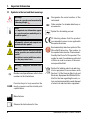
1. Important Information
1.1 Symbols in the text and their meanings
Warnings
appear in a gray box and are marked by
a warning triangle .
Notes
i.e. important user information appear
in a gray box and are marked by an information symbol .
Inflammable solvent and reagents are
marked with this symbol.
Instrument surfaces which become hot
during operation are marked with this
symbol.
Avoid direct contact with these surfaces - they may cause burns.
Warning – Dangerous electrical voltage.
(5)
Numbers and parentheses refer to item
numbers in the illustrations.
Function keys to be pressed on the
LOAD touch screen are written in bold-print
capital letters.
SN
Designates the serial number of the
instrument.
REF Order number for standard delivery or
accessories.
Symbol for alternating current
CE labeling shows that the product
corresponds to one or more applicable
European directives.
Environmental protection symbol of the
China RoHS directive. The number in
the symbol indicates the "Environmentfriendly Use Period" of the product. The
symbol is used if a substance restricted
in China is used in excess of the maximum permitted limit.
Symbol for labeling electrical and electronic equipment in accordance with
Section 7 of the German Electrical and
Electronic Equipment Act (ElektroG). ElektroG is the law regarding the sale, return and environmentally sound disposal
of electrical and electronic equipment.
Manufacturer
Observe the Instructions for Use.
6
Instructions for Use V 1.9 RevD - 05/2013
1. Important Information
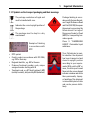
1.1.1Symbols on the transport packaging and their meanings
The package contents are fragile and
must be handled with care.
Indicates the correct upright position of
the package.
The package must be kept in a dry
environment.
Example of labeling
in accordance with
IPPC
• IPPC symbol
• Country code in accordance with ISO 3166,
e.g. DE for Germany
• Regional identifier, e.g. HE for Hessen
• Producer/treatment provider code, unique
assigned number starting with 49
• Treatment code, e.g. HT (heat treatment), MB
(methyl bromide), and possibly DB (debarked)
Leica IP S
Package labeling in accordance with German Hazardous Freight Ordinance Road
and Rail (GGVSE)/European
Agreement concerning the
International Carriage of
Dangerous Goods by Road
(ADR) for transporting hazardous goods.
Class 3: "FLAMMABLE
LIQUID" - Flammable liquid
substance.
Tip-n-Tell indicator to monitor whether the shipment
has been transported and
stored in upright position
according to your requirements. With a pitch of 60° or
more, the blue quartz sand
flows into the arrow-shaped
indicator window and sticks
there permanently. Improper handling of the shipment
is immediately detectable
and can be proven definitively.
7
1. Important Information
1.2 Qualification of personnel
1.4 Instrument type
• The Leica IP S may be operated by trained
laboratory personnel only.
• All laboratory personnel designated to operate
this instrument must read these Instructions
for Use carefully and must be familiar with all
technical features of the instrument before
attempting to operate it.
All information provided in these Instructions for
Use applies only to the instrument type indicated
on the cover page.
A name plate indicating the instrument serial
number is attached to the back of the instrument.
1.3 Intended use of instrument
Leica IP S printer system for standard specimen
slides.
• The instrument has been designed for use
in pathology, histology, cytology, toxicology
and similar laboratories, and there only for
standard specimen slides.
• Imprints of adequate quality and resistance
to subsequent processing in tissue processors can only be guaranteed when using the
specimen slides and reagents specified in
Chapter 3.3.
• The instrument must be used exclusively according to the instructions contained in these
Instructions for Use.
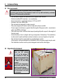
Fig. 1
Fig. 1 is provided as an example only
and shows a valid nameplate for this
instrument with the necessary information about instrument type and
power requirement. The precise data
for the various versions is specified in
Chapter 3.2, "Technical data".
Proper and intended use includes the
observance of all instructions in the
Instructions for Use and compliance
with all inspection and maintenance
instructions.
Any other use of the instrument is
considered improper!
8
Instructions for Use V 1.9 RevD - 05/2013
2. Safety
Make sure to comply with the safety instructions and warnings in this chapter.
Make sure to read these instructions, even if you are already familiar with the operation and
use of other products.
2.1 Safety instructions
These Instructions for Use include important
instructions and information related to the operating safety and maintenance of the instrument.
The Instructions for Use are an important part of
the product, and must be read carefully prior to
startup and use and must always be kept near
the instrument.
This instrument has been built and tested in accordance with the safety regulations for electrical measuring, control, regulating and laboratory
devices.
To maintain this condition and ensure safe
operation, the user must observe all notes and
warnings contained in these Instructions for Use.
These Instructions for Use must be appropriately supplemented as required by the existing regulations on accident prevention and environmental safety in the operator's country.
The protective devices on both instrument and accessories may neither be removed nor modified. Only authorized and qualified service personnel may access and repair the internal components of the instrument.
Use only the provided power cable - this must not be replaced with a different power cable. If
the power plug does not fit in your socket, contact our service.
Residual risks
The instrument has been designed and constructed with the latest state-of-the-art technology
and according to recognized standards and regulations with regard to safety technology. Operating or handling the instrument incorrectly can place the user or other personnel at risk of
injury or can cause damage to the instrument or other property. The machine may be used only
as intended and only if all of its safety features are in proper working condition. Malfunctions
that impede safety must be remedied immediately.
For current information about applicable guidelines, please refer to the CE declaration of conformity and on our Internet site at:
http://www.LeicaBiosystems.com
Leica IP S
9
2.Safety
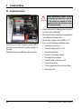
2.2Warnings
The safety devices installed in this instrument by the manufacturer only constitute the basis for
accident prevention. Primarily responsible for accident-free operation is above all the institution
which owns the instrument and, in addition, the designated personnel who operates, services
or repairs the instrument.
To ensure trouble-free operation of the instrument, make sure to comply with the following
instructions and warnings.
Warnings—Transport and Installation
• Once unpacked, the instrument may be transported only in an upright position.
• Do not expose the instrument to direct light (window, lamps with strong light)!
• Only connect the instrument to a grounded power socket. Do not interfere with the grounding
function by using an extension cord without a ground wire.
• Do not operate the instrument in rooms with explosion hazard.
• Condensation water may form in the instrument, if there is an extreme difference in temperature between the warehouse and the installation site and if air humidity is high at the same
time. If this is the case, wait at least two hours before switching on the instrument. Failure to
adhere to this waiting period may result in damage to the instrument.
Warnings—Markings on the instrument itself
• Markings on the instrument showing the warning triangle indicate that the correct operating
instructions (as defined in these Instructions for Use) must be followed when operating or
replacing the item marked.
• Failure to adhere to these instructions may lead to accidents causing personal injury and/or
damage to the instrument or accessories or destroyed, unusable slides.
• Some instrument surfaces become hot during operation. They are marked with this warning
label. Touching these surfaces may cause burns.
10
Instructions for Use V 1.9 RevD - 05/2013
2. Safety
Warnings—Instrument operation
• The instrument may be operated by trained laboratory personnel only. It must only be operated for the purpose of its designated use and according to the instructions contained in these
Instructions for Use.
• The instrument is de-energized after disconnection of the power supply through the power
cable (power supply circuit breaker) - in emergencies, disconnect the power plug.
• Do not touch the chute during operation. Risk of injury.
• Do not open the reflector flap of the flashlight while the instrument is ON—risk of burns and
blinding. • The device operator is obligated to conform to the local workplace limit values and to document them.
Warnings—Cleaning and maintenance
• Before any maintenance, switch off the instrument and unplug it from power supply.
• To clean the exterior surfaces, use a mild and ph-neutral commercial household cleaner.
You may NOT use: Alcohol, cleaning materials containing alcohol (glass cleaner!), abrasives, or solvents containing acetone or xylene!
• The painted surfaces and the control panel of the instrument are not resistant to xylene or
acetone!
• While working and during cleaning, no liquid may get into the interior of the instrument.
Leica IP S
11
3. Instrument Components and Specifications
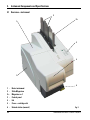
3.1Overview—instrument
2
1
2.1
3
4
5
6
1 - Basic instrument
2 - Slide Magazines
2.1- Magazine no. 1
3 - Control panel
4- Lid
5 - Cover—cartridge slot
6 - Unload station (manual)
12
Fig. 2
Instructions for Use V 1.9 RevD - 05/2013
3. Instrument Components and Specifications
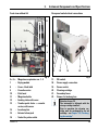
Front view without lid
Rear panel and electrical connections
12
2.1 -2.3
7
8
10
11
3
2
1
13
9
17
15
14
16
21
Fig. 3
2.1-2.3- Magazine receptacles nos. 1 - 3
7 - Drying module
8 - Cover—flash bulb
9 - Cassette carrier
10 - Print head
11 - Magazine holder
12 - Feeding chute with cover
13 -Transfer point: chute --> cassette
carrier, with sensor
14 - Location plate
15 - External alarm jack
16 - Socket for printer cable
Leica IP S
17 -
18 -
19 -
20 -
21 -
22 -
19
18
DIL switch
Power supply connection
Power switch
Cleaning cartridge
Secondary fuses
Drawer for broken glass
20
22
Fig. 4
Attention for pos. 20.
The instrument is delivered with the
storage cartridge installed!
Prior to operation, the cleaning cartridge must be exchanged for an ink
cartridge - see Chapter 4.10, "Exchanging the cartridge".
13
3. Instrument Components and Specifications
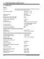
3.2 Technical data
General
Approvals:The instrument-specific approval marks are located at the rear panel
of the instrument, next to the name plate.
Nominal supply voltages:
100 to 120 V ~ +/- 10 %
200 to 240 V ~ +/- 10 %
Nominal frequency:
50 to 60 Hz
Power fuse:
2x T 3.15 A L250 V
Maximum power draw at 100 - 120 V:
4.0 A
Maximum power draw at 200 - 240 V:
2.8 A
Leakage current at 240 V/50 Hz:
ca. 2.4 mA
Nominal power:
700 VA
IEC 1010 classification:
Protection class 1, pollution degree 2
Overvoltage installation category II
Operating elevation:
up to max. 2000 m NN
A-weighted noise level:
< 70 dB (A)
IP protection class (IEC 60529)
IP20
Climatic conditions for the operation of the instrument:
Temperature:
+15 °C to +30 °C
Relative humidity:
20 - 80 % - non-condensing
Climatic conditions for the storage and transport of the packaged instrument:
Storage temperature range:
+5 °C to +40 °C
Transport temperature range:
-29 °C to +40 °C
Relative humidity:
10 - 85 % - non-condensing
Dimensions and weight
Dimensions of basic instrument
Width x depth:
Height with magazine:
Dimensions with unload station connected
Width x depth:
Height with magazine:
Basic instrument empty weight:
Weight, packed:
Unload station empty weight:
Weight, packed:
14
475 x 650 mm
560 mm
548 x 650 mm
655 mm
approx. 28 kg
approx. 65 kg
approx. 14 kg
approx. 32 kg
Instructions for Use V 1.9 RevD - 05/2013
3. Instrument Components and Specifications
Performance
Load capacity:
Printing speed 1:
Printing batch jobs:
Single-cassette printing:
Ink cartridge capacity 2:
Flash bulb lifetime:
14 slides/minute
(two-line printing)
10 s per slide
approx. 60,000 printouts or 3.5 months
approx. 150,000 flashes
Printing
Print resolution 3:
Printing medium:
Print format:
Pressure surfaces:
360 x 360 dpi / 180 x 180 dpi, adjustable
Glass specimen slide with coated field
76 x 26 mm, max. 1.2 mm thick
Slide
max. 25.4 x 18.0 mm
PC system requirements
IBM-compatible PC
Processor clock frequency: Main memory (RAM): Hard disk: CD-ROM drive
1 free serial port
Operating system: up to 3 magazines,
up to 150 slides per magazine
min. 800 Mhz
min. 256 MB
min. 6 GB
Windows NT, Windows 2000, Windows XP
Windows VISTA, Windows 7 (32 bit and
64 bit)
) Average value—exact speed in each individual case depending on system configuration and the
software used.
2
) Average value—exact number of cassettes in each individual case depending on quantity being
imprinted and on density of imprint.
3
) Measured in addressable dots per inch
1
Leica IP S
15
3. Instrument Components and Specifications
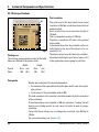
3.3 Print specifications
Only standard specimen slides with imprintable colored edges (23) can be imprinted in the
Leica IP S (see Fig. 5).
Printing directly onto the glass is not possible.
Specimen slides with the following dimensions
can be processed: 76 x 26 mm, max. 1.2 mm thick.
Specimen slides with a white printed surface
should be checked for print quality and ink resistance before purchase.
Some slides have been coated over the print
surface as well as the glass, which can create
problems with the adherence of the ink. These
slides should also be tested for print quality and
ink adherence before purchase.
3.3.1Requirements for specimen slides
23
Fig. 5
The texture of the slide print surface is extremely
important for optimal print quality and durability.
The print surface varies considerably between
manufacturers, color selection and coated (positively charged) versus uncoated surfaces.
They can even vary greatly from slide to slide in
the same lot. Colored print surfaces, other than
pure white, contain pigments that help the ink
spread evenly and adhere strongly.
16
• To reduce the amount of glass dust and the
risk of mechanical failures, use only clipped
corner slides (45° angle on each corner, Fig. 5).
• Slides to be used in the printers must be
stored appropriately in closed containers and
protected from dust and moisture.
• Positively charged slides are inherently sticky
so they require special handling to insure reliable mechanical handling by the instrument.
• When the print job is complete, the printed surface of the slide may be handled immediately.
Please be aware, however, that the special
ink is alcohol-based and exposure to alcohol
in combination with physical contact (rubbing) could cause the print quality to degrade
significantly.
Instructions for Use V 1.9 RevD - 05/2013
3. Instrument Components and Specifications
Tested and recommended print media for the Leica IP S ink jet printer
Important!
The use of other print media may result in unsatisfactory print quality and/or jamming of slides/
cassettes during the printing process!
If the specimen slides you are currently using are not listed above, please contact your local
Leica Biosystems representative.
Specimen slides recommended by Leica are:
• Leica Snowcoat ® Clipped Corner Slide
• Leica Clipped Corner X-tra ® Adhesive Slides
Caution!
Slides made by other manufacturers must be tested before use.
The test must include the following steps:
Mechanical compatibility with the instrument.
Imprint quality.
Chemical and mechanical resistance of the imprints against the reagents the slides will be
exposed to during the subsequent processing steps (see also Chapter 3.3.4).
Important!
Leica Biosystems assumes no responsibility whatsoever for any damages suffered as a consequence of imprints of poor quality or imprints made with non-reagent-resistant ink.
Leica IP S
17
3. Instrument Components and Specifications
3.3.2Print specifications
Print resolution
24
Fig. 6
Printing area
The printing area parameters listed in the table
below are defined in the printer driver.
Width
Format Dots mm
Slide
360 25.4
Print quality
18
The print head of the instrument has a preset
resolution of 360 dpi in both directions (vertical
and horizontal).
Each printed line has a maximum height of
128 dots.
This corresponds to a value of 9.03 mm.
Therefore, a maximum of 2 lines can be printed
on the slides.
In horizontal direction, the printable surface is
limited only by the size of the object to be imprinted (Fig. 6).
The above values must be taken into consideration when defining the print area ("paper size")
in the application you are going to print from.
Height
Dots mm
256
18.0
Quality and resolution of the imprints depend on:
• the material of the imprintable surface/the dyes used to color the imprintable surface.
• the structure of the imprintable surface (24).
The final resolution of the imprints is not determined only by the resolution
of the print head.
If the slide surface is not capable of 360 dpi resolution, "running" ink will
lead to poor printing results. In such cases it is better to work at a lower
resolution.
The printer driver allows you to change the resolution from 360 dpi to
180 dpi.
(For more information, see Chapter 5.4).
Instructions for Use V 1.9 RevD - 05/2013
3. Instrument Components and Specifications
3.3.3Printing bar code
Printer technology
Creating bar codes
Printing readable bar code depends on various factors that need to be
taken into consideration in order to achieve results suitable for reliable and
durable archiving. The main factors influencing the bar code results are:
• printer technology
• how the bar code is created
• the type of object being printed on
• the type of scanner used to read the bar code
• As a dot matrix printer, the IP S can handle information only in the form
of dots printed or not printed. It is not possible to transmit bar code data
or to select specific bar code types or use the printer to create and print
the bar code required.
• Since there is only limited printing space on the slides, the bar code
should not contain more information than necessary.
• You should use an error-checking code, which makes it easier for the
bar code scanners to recognize possible errors. Some codes even support error correction.
• When calculating and creating bar code, always bear in mind the resolution of the printer.
The module size is the width of the smallest element of a bar code. Wider
bars and spaces are calculated in multiples of the module size.
The module size always has to be an entire divisor of the printer resolution, as, due to the technology applied, only 'whole' dots can be printed.
Reading errors may occur (even if the print appears to be crisp and correct), if, due to conversion, module width and resolution do not match
any longer.
Data should never be printed as bar code only, but also as text
(line of optical characters above or below the bar code), to ensure
that no information is lost for the above reasons.
Leica IP S
19
3. Instrument Components and Specifications
Requirements for bar code printing
The quality and readability of printed bar codes will depend on several
factors that include:
• Texture and quality of the print surface on the selected surface of the
slide
• The color of the title block
• Bar code style (1D or 2D)
• Number and types of characters required in the bar code
• The quality and resolution capabilities of the bar code reader
As always, using Leica recommended print media will produce the highest
quality print. However, it is highly recommended that any bar code solution
be tested prior to implementation. Please check with your local representative for details on achieving the maximum number of characters with 2 D
bar codes.
Bar code scanners
The scanning results obtained not only depend on the correct bar code
creation and on the quality of the specimen slides, but also on the features
of the bar code scanner used.
Features to bear in mind are:
• Reading tolerance:
difference between actual bar width and nominal module size.
• Light color:
In order to obtain a high contrast with the specimen slides used.
• Optical resolution:
must be better than the module size.
Depending on the application, the following features should also be
considered:
• Maximum readable distance
• Maximum inclination angle
Leica has successfully tested the following readers:
Symbol DS 6707 Bar code Scanner
Fig. 7
20
Instructions for Use V 1.9 RevD - 05/2013
3. Instrument Components and Specifications
3.3.4Resistance against reagents
Caution!
All laboratories must perform their own tests to ensure that the ink is resistant against the various reagents the slides will subsequently be exposed to.
A wide range of factors beyond Leica's control can have negative effects on the results.
The test conditions stated below can therefore only serve as an outline for individual laboratory test specifications.
The laboratory operating the unit shall bear full responsibility for the legibility of the imprint
after processing with reagents.
Test conditions
Imprinted slides were tested with a variety of reagents in an environment
simulating the conditions present during tissue processing.
The following slide types were tested:
• Leica
– Snowcoat ® Clipped Corner Slide
• Leica
– Clipped Corner X-tra ® Adhesive Slides
• Erie Scientific – Superfrost (plain and plus)
• Knit tel GmbH – Printer slides, adhesive slides
• Marienfeld – Unimark
• Menzel
– Superfrost, Superfrost Plus
• Thermo
– Colorfrost Plus
A variety of colors of all of the above slide types (although not all colors
available of each slide type) were tested.
An influence of the slide color on the resistance of the imprint could not be
verified.
It cannot be guaranteed that the ink will be absolutely smudge-proof under all foreseeable laboratory conditions, as stability of the ink against wiping largely depends on the surface structure of the imprint field of the slide being imprinted.
Important!
The imprint field of imprinted slides should never be touched or wiped while damp.
Leica IP S
21
4. Instrument Setup
4.1 Site requirements
The instrument must not be operated in areas at risk of explosion.
To ensure proper function of the instrument, it must be set up while maintaining a minimum
distance of 10 cm from walls and furniture.
-
-
-
-
-
-
-
-
-
-
-
The instrument requires an installation area of approx. 650 x 550 mm.
Relative humidity 80 % maximum - non-condensing
Room temperature consistently between +15 °C and +35 °C
Elevation: up to max. 2000 m NN
The instrument is designed for indoor use only.
The power plug/circuit breaker must be freely and easily accessible.
Power supply at a distance no greater than the length of the power cable – an extension
cable must NOT be attached.
The bench must have a sufficient load capacity and rigidity with respect to the weight of
the instrument.
Avoid vibrations, direct sunlight, and large temperature fluctuations. The installation
location must be well ventilated, and must contain no sources of ignition of any kind.
The instrument must be connected to a grounded power socket.
Only a power cable provided which is intended for the local power supply may be used.
The installation location must be protected against electrostatic discharges.
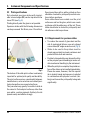
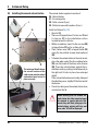
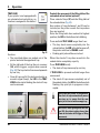
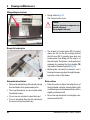
4.2 Unpacking the Instrument
When the instrument arrives,
check the tilt indicator
(1, Fig. 8) on the package. If
the arrowhead is blue, the
shipment was transported laying flat, was tilted at too great
an angle or fell over during
transport.
Note this on the shipping documents and check the shipment for possible damage.
Only personnel authorized by
Leica may unpack and install
the instrument.
2
1
3
3
Fig. 8
22
Instructions for Use V 1.9 - 08/2012
4. Instrument Setup
• Unscrew the 8 screws (2, Fig. 8) on the sides
of the wooden box and loosen the cover.
• Remove the accessory box (7, Fig. 9) including
accessories and packaging material) - directly
under the lid.
• Unscrew the 8 screws (3, Fig. 8) on the floor
of the wooden box on the exterior.
• Remove the interior carton around the instrument.
• Carefully remove the wooden box from the
baseplate.
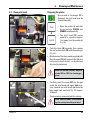
• The printer is secured with 4 plates (5) on
the wooden floor of the outside box. Loosen
the two screws (4, Fig. 10) on the base of the
instrument. Remove the plate from the bottom.
• Place the printer from the baseplate on a
stable laboratory bench - or, if present, on the
automated unload station. Make sure that the
stage is leveled!
When unpacking the printer, at least
two people (one person on each side
of the printer) are required to lift the
printer out of the box and place it onto
the laboratory bench.
5
4
5
Fig. 10
6
Fig. 11
• If the instrument was set up at its final area of
use, remove the blue foam transport anchor
(6, Fig. 11) (pull upwards).
7
Fig. 9
Leica IP S
23
4. Instrument Setup
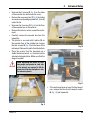
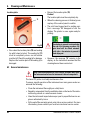
4.3 Installing the printer
When unpacking the printer, at least
two people (one person on each side
of the printer) are required to lift the
printer out of the box and place it onto
the laboratory bench.
27
Fig. 12
Carefully pull out the transport anchor (27) of
foam that protects the print head by pulling it to
the right.
Carefully remove any adhesive tape remnants.
24
• Check instrument for damage (do not switch
on in the case of damage!).
• Check delivered accessories for completeness
according to purchase order.
• Remove the transport anchor (27, Fig. 12).
• Carry out the following installation steps:
• Install the accessories.
• Insert shielding glass (Fig. 16).
• Insert the flash bulb.
• Connect to the power supply.
• Exchange the cartridges.
• Establish data connection to PC.
• Install printer driver.
• Fill the magazines with specimen slides.
• Run a test print.
Instructions for Use V 1.9 RevD - 05/2013
4. Instrument Setup
4.4 Standard delivery—packing list
The standard equipment of the Leica IP S includes the following parts:
1 Leica IP S, basic instrument without unload station
1 Cleaning cartridge (in the instrument)
1 UV ink cartridge Leica
1 Unload station S (manual), complete
1 Accessory kit consisting of:
1 Flash bulb
3 Magazines for slides, (1 pack of 3)
1 Set of power cords:
1 Power cord for UK ST/BU F-5A
1 Power cord for Germany
1 Power cord for USA/Canada/Japan
1 Printer cable, serial
1 Tool set, consisting of:
1 Slotted screwdriver 4 x 100
1 Allen key size 2.5
1 Leica brush
1 Set of replacement fuses:
2 Fuses 3.15 A T (5 x 20 mm)
1 Protecting block (in the instrument)
2 Shielding glass 2 Location plates 2 Transport plates
1 Cleaning swabs, pack of 25
1 Instructions for Use, english
1 Language CD (+ printer driver with documentation)
14 6943 03150
14 0601 39615
14 0601 42533
14 0601 40162
14 0601 40196
14 0601 39637
14 0601 85101
14 0602 80200
Optional accessories:
• Automated multi-level cassette unload station (for Leica IP S) • Set of slide trays for unload station S (pack of 10)
• Magazine holder "S" for 6 magazines
• Magazine loading help • Cartridge kit, 310 ml
14 0601 33225
14 0601 33252
14 0601 36940
14 0601 35979
14 0601 43506
Leica IP S
14 0601 33201
14 0601 42865
14 0601 42350
14 0601 35990
14 0601 38350
14 0601 37152
14 0601 36689
14 0411 36959
14 0411 36958
14 0411 36960
14 0601 37044
14 0601 37000
14 0170 38405
14 0222 04137
14 0183 30751
25
4. Instrument Setup
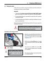
4.5 Installing the manual unload station
4
30
31
28
31
The enlarged detail shows
the correct location of the
collar screw once the unload
station has been locked in
place correctly.
26
32
27
The unload station supplied consists of:
26 - Unload station
27 - Screening plate
28 - Collar screws (3 pcs.)
29 - Slotted screws with washers (2 pcs.)
Install as follows (Fig. 13):
• Open lid (4).
• There are 5 tapped holes (2 x item no. 30 and
3 x item no. 31) in the installation surface
located below the reflector.
• With a screwdriver, insert 3 collar screws (28)
in tapped holes (31) as far as they will go.
• Then, fasten cover (27) in tapped holes (30)
using the two slotted screws (and washers)
(29).
• To fasten the unload station to the instrument,
place the wider end of the three oblong holes
(32) over the heads of the three collar screws
(28). Press the unload station against the installation surface, pushing it simultaneously to
the right until it locks in place (see enlarged
detail).
If the unload station does not easily slide past
the shielding cover, slightly lift the front end of
the device.
• Close lid, making sure the unload station does
not obstruct the lid.
When working with the manual unload station the slides imprinted must
be removed in regular intervals. Otherwise they will start piling up in the
unload station, printing will stop and
error code "44" will be displayed.
28
29
Fig. 13
26
Instructions for Use V 1.9 RevD - 05/2013
4. Instrument Setup
4.6 Automated unload station (optional)
Optionally available for the printer is an automated multi-level cassette unload station, where
the imprinted specimen slides are collected on
individually removable and stackable trays (40)
in the order in which they were printed.
The multi-cassette unload station comes complete with 10 trays, all of which can be inserted
simultaneously. Each tray holds up to 11 slides.
Installing the multi-cassette unload station:
• Unpack the unload station and place it on a
stable laboratory bench at the installation site.
40
39
38
36
35
36
37
Fig. 14
Leica IP S
Important!
Prior to installation, the printer must
be switched off and unplugged from
power supply.
The manual unload station (chapter 4.5)
The collar screws (30, Fig. 13) must also
be removed prior to placing the printer
onto the automated unload station.
• Place the instrument onto the unload station.
2 persons are required to do this!
• Hold the printer on both sides (right and left)
and first insert the two rear bolts (35, Fig. 14)
of the unload station into the openings in the
base plate of the printer.
Then carefully lower the front part of the
printer unto the third bolt (36) so that the plug
connection (37) locks into place in the printer
base plate and the printer remains securely
fastened on the unload station.
• Place the stack of trays (39) onto the lifting table
(38) of the automated unload station. See chapter 5.2 for details on the lifting table controls.
27
4. Instrument Setup
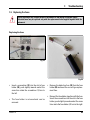
4.7 Installing/exchanging the flash bulb
41
49
42
Removing the old flash bulb
Switch the instrument off and unplug it
from power supply.
Allow the flash tube to cool before removing it. Do not handle the flash tube
with bare hands. Use a glove or tissue.
• Open the lid (4, Fig. 2) to gain access to the
reflector.
• Remove screw (49) (use screwdriver supplied
as part of tool set). Mind the washer (42).
Fig. 15
Caution!
To insert/remove, hold the flash
bulb as shown in Fig. 17 (right).
Do not take hold of the sides of
the flash bulb or compress it as
shown in Fig. 16.
Fig. 16
Fig. 17
• Swing the reflector (41) upwards.
43
• Carefully pull out the old flash bulb (43) straight
to the right, do not twist it. If the flash bulb
cannot be pulled out easily, gently rock it back
and forth to get it unseated from the socket.
• Make sure the contact spring (44) is removed
from the priming wire (45) of the lamp.
(See also Fig. 19 and 22)
44
Fig. 18
28
Instructions for Use V 1.9 RevD - 05/2013
4. Instrument Setup
Inserting the new flash bulb
86
44
46
85
86
47
Fig. 19
48
47
Fig. 21
45
Fig. 20
• Insert the shielding glass (85) in the two holders (86).
• Insert the new flash bulb into socket (46)
(Fig. 21); then push it carefully inwards as far
as it will go (Fig. 22) (the polarity marker (+)
must not be visible any longer). If necessary,
move flash bulb gently up and down.
• Important! Make sure that the new flash bulb
is inserted correctly – the lamp electrode
(47) marked with a + must be inserted into
the socket (46) that bears the same mark (48)
(Fig. 21).
Caution!
If the lamp electrodes are inserted the
wrong way, the flash bulb will still
work, but the lifetime will be significantly reduced.
45
• The contact spring (44) has to touch the ignition wire (45) of the lamp after being inserted.
• Swing the reflector downwards. Reinsert and
retighten screw (49).
• Close lid (4) of the instrument again.
44
Fig. 22
Leica IP S
29
4. Instrument Setup
4.8 Filling and inserting the magazines
48
51
50
49
52
Fig. 23
Fig. 24
Fig. 25
• Fill one of the magazines (48) with slides (49).
While doing so, ensure that the surface to be
imprinted (50) is on the left and facing upwards
(Fig. 23).
Fig. 26
• So that the specimen slides are ejected correctly, ensure that the specimen slides are
inserted into the magazine accurately aligned
above each other (Fig. 26) and at a right angle
to the aperture (Fig. 27).
• Hold magazine (48) at a slight angle (Fig. 24)
to prevent the specimen slides from falling
out of the magazine. Insert magazine into the
corresponding receptacle as shown. Both pins
(52) of the magazine need to lock into slot (51).
Fig. 27
30
Instructions for Use V 1.9 RevD - 05/2013
4. Instrument Setup
Filling and inserting the magazines (continued)
Filling capacities:
Each magazine can hold up to 150 slides
(depending on individual slide thickness).
The maximum filling height of a magazine is indicated by the "max." mark (74) and may not be
exceeded (Fig. 28).
48
74
Positively charged slides cling to each other so
much that they require special handling to ensure reliable mechanical handling of this type of
specimen slide by the printer.
If you are using positively charged slides, please
follow the recommendations below:
• Positively charged specimen slides must be
separated from each other before they are
loaded into the magazine.
• The magazine may be loaded with no more
than 72 specimen slides to prevent problems
during ejection. This corresponds to the lowest
mark (75).
• Even smaller loads will significantly improve
the ability of the instrument to eject positively
charged slides from the magazine.
75
Fig. 28
Leica IP S
31
4. Instrument Setup
4.9 Electrical connection
The instrument must be connected to a grounded power socket.
Of the set of power cords supplied, be sure to use only the one that is appropriate for the local
power supply (plug must fit on-site wall outlet).
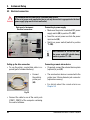
Connecting to power supply
• Make sure the printer is switched OFF, power
supply switch (62) in position "0" = OFF.
• Insert the correct power cord into the power
input socket (63).
• Switch on power switch (switch to position
"I"= ON).
Back panel of instrument
Electrical connections
62
61
63
60
Fig. 29
Setting up the data connection
• To use the printer, a serial data cable is required (part of standard delivery).
• Connect
the cable to
printer port
(60).
Once switched on for the first time,
the power switch (62) should always
remain in position "I" = ON.
Connecting a remote alarm device
• If required, connect the external alarm system
(optional) to jack (61).
• The remote alarm device is connected to the
printer via a 3.5 mm-diameter jack connector
(optional accessory).
• For details about the remote alarm see
Chapter 5.3.
Fig. 30
• Connect the cable to one of the serial ports
(COM 1, COM 2) of the computer containing
the control software.
32
Instructions for Use V 1.9 RevD - 05/2013
4. Instrument Setup
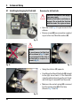
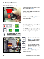
4.10 Exchanging the cartridge
4
5
85
64
Fig. 31
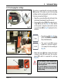
The printer is supplied with a cleaning cartridge
(64) inserted. To be able to print, the cleaning
cartridge must be exchanged for an ink cartridge.
To do so, proceed as follows:
• Open the cover plate (5) on the left side of the
instrument (pressing its top left corner).
• Unscrew the red cap (85) of the cleaning cartridge (64) by one turn (Fig. 31), then switch
on the printer using the main switch on the
rear side (item (62) in Fig. 23) and wait for it to
initialize.
72
73
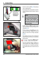
• Open the hood (4 in Fig. 31), then
press the CLEAN and LOADED
keys simultaneously.
• The print head (72) moves
upward to a position approx.
1 cm away from the sealing lip
(Fig. 32).
69
Fig. 32
73
• Raise the lever (69) then remove the black
transport plate (73) and insert the location
plate (70), which is required for printing
(Fig. 33).
Do not reinstall a used transport plate
(73), as it will no longer completely
seal the print head.
To prevent damage to the print head,
always use the red location plate (70)
when printing.
70
Fig. 33
Leica IP S
33
4. Instrument Setup
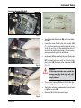
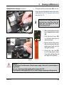
Exchanging the cartridge (continued)
ð
The last 30 seconds before the
head closes are
counted down.
Fig. 34
85
Caution!
If no key is pressed, the print head will
close automatically 150 seconds after
opening to prevent it from drying out.
An acoustic signal (5
beeps) will
sound after 120 seconds, after which
the final 30 seconds will be counted
down on the display.
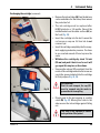
• Push the safety catch (86) forwards/to the right
(open), so that the cleaning cartridge can be
removed (Fig. 35).
86
• Pull the cleaning cartridge (64) approx. 3 cm
out of the instrument, retighten the red cap
(85), then remove the cartridge completely
(Fig. 36).
64
Fig. 35
64
• The activation of a sensor in the cartridge slot
blocks all functions so that no air is sucked into
the ink system.
The indicator LED "Ink Empty"
lights up and remains ON.
• Store the removed cleaning cartridge in a
sealed container. The cartridge is full and can
be used twice more to clean the print head.
The expiration date can be found on the red
label.
85
34
• Push the small lever (69, Fig. 32) back down
into its original position.
• Press any key of the control panel to reposition
the print head and make the printer ready to
operate.
Fig. 36
Instructions for Use V 1.9 RevD - 05/2013
4. Instrument Setup
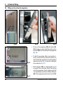
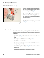
Exchanging the cartridge (continued)
66
Fig. 37
87
Fig. 38
65
Fig. 39
• Remove the ink cartridge (66) from the delivery
carton and shake it a few times, then remove
the protective foil.
• The ink cartridge must be replaced after
60,000 printouts or 3.5 months. Record the
installation date on the white surface (65) on
the front (Fig. 39).
• Insert the cartridge into the slot. Loosen the
red screw-on cap one full turn but do not
remove it yet.
• Insert the cartridge completely into the receptacle applying moderate pressure. You have
to use a certain amount of force to pierce the
seals.
• Withdraw the cartridge by about 1� inch
(30 mm) and push it back in as far as it will
go; repeat this step two or three times.
• Unscrew the red cap (87) completely from the
nozzle of the cartridge and store the screw-on
cap in the groove indented into the cartridge
for that purpose (Fig. 38, 39).
Very important!
Prior to each transport, the cap (87)
must be screwed onto the nozzle to
prevent the ink from spilling.
• Directly next to the slot opening is a safety
catch (86, Fig. 40). Moving this catch to the
side secures the ink cartridge against falling
out.
86
This step is very important to ensure
safe operation of the printer!
Fig. 40
Leica IP S
35
4. Instrument Setup
Exchanging the cartridge (continued) • The sensor in the cartridge slot recognizes the presence of a
new cartridge.
ð
• The indicator LED "Ink Empty" goes out, code "88" appears in
the display.
At this point, the instrument has to be "told" which type of cartridge has been
inserted.
There are three options:
1. New ink cartridge:
Press LOADED; the printer sets the ink level meter to 'full'.
2. Used ink cartridge:
Press ERROR; the printer resumes measuring at the ink level where it
previously left off.
CAUTION!
NEVER press CLEAN while an ink cartridge is in the instrument! The
entire contents of the ink cartridge will spill into the printer.
3. Used or new storage fluid cartridge:
Press the key CLEAN; the current ink level is stored.
The fill level of the cleaning cartridge is not monitored. Each use
should be noted on the cartridge. The cartridge can be used twice.
The cycle time when inserting a cleaning cartridge is 3.5 minutes
and is thus considerably longer than that of an ink cartridge.
ð
Running a test print
• After one of the three buttons has been pressed, the ink exchange software
routine starts; air is evacuated from the hoses and the system is refilled
with liquid.
• Display indication "88" is extinguished once the ink exchange has been
completed.
• Run a test print to verify whether the printing head works correctly.
• For that purpose, fill some specimen slides into a magazine and insert
the magazine into magazine position 1.
• Press and hold the CLEAN button until "00" is displayed, then release
the button. A specimen slide is imprinted with a test image stored in the
printer for that purpose. If the print result is not satisfactory, this step
can be repeated several times.
36
Instructions for Use V 1.9 RevD - 05/2013
4. Instrument Setup
4.11 Installing the printer driver
This printer driver only runs under the operating systems Microsoft Windows NT 4.0, Windows 2000 and Windows XP. Installation described is for Windows 2000. Any steps that need
to be carried out in a different way when installing under other Windows versions are also
explained below.
"Microsoft", "Windows NT", "Windows 2000", “Windows XP” and “Windows 7 (32 bit and
64 bit)” are registered trademarks of Microsoft Corporation.
You must have administrator rights to be able to install the printer driver.
Starting installation:
1. Open the printer folder:
START --> SETTINGS --> PRINTERS
2. Double-click the ADD PRINTER icon. The ADD PRINTER WIZARD, which
guides you through the rest of the installation, is started.
Add printer wizard
1. The printer is controlled by the computer to which it is connected; therefore, MY COMPUTER must be selected.
2. Insert the correct information—according to your current system—in
the dialog boxes that follow. Click NEXT to move on to the next dialog
box.
3. In the next dialog box, an available serial interface (COM 1, etc.) must be
selected, as the printer only works with RS 232 interfaces. Do not select
a parallel printer port (LPT ...)!
4. Next, select the printer manufacturer and model. Click HAVE DISK... to
open the INSTALL FROM DISK dialog box.
5. Insert the CD containing the printer driver (part of standard delivery) into
the CD-ROM drive and enter the following path in the input field:
X:\IP_Driver\IP_S\English (for English user interface) and confirm with OK. "X" is to be replaced by the letter corresponding to the drive
containing the CD.
Leica IP S
37
4. Instrument Setup
6. In the selection window, select PRINTERS IP-S (blue mark).
If no (or other) selectable options are displayed, click on "HAVE
DISK..." to return to the previous dialog box and repeat insertion of
the path.
7. If the message shown on the left is displayed, the driver has already
been installed on your PC on a previous occasion (e.g. interrupted installation or update).
In this case, be sure to select REPLACE EXISTING DRIVER.
8. In the PRINTER NAME: box, you can insert any printer name you wish—
the printer name you insert will subsequently be displayed in the printer
folder and in the PRINT menu of all other Windows applications.
To avoid erroneous printouts, select NO when asked whether you want
to use this printer as the default printer.
9. Two more on-screen prompts will be displayed:
• When prompted whether you wish to share the printer in a network,
select --> NOT SHARED, if the printer is used on a local host.
• When prompted whether you would like to print a test page,
select --> NO.
10.Click the FINISH button to complete the installation of the printer driver.
The printer name selected in step 8 (see above) will be displayed in the
printer folder and in all print menus.
When installing under Windows 2000 or Windows XP, at this point
the message "DIGITAL SIGNATURE NOT FOUND" will be displayed.
This message is displayed simply to inform you that the printer driver has not yet been certified by Microsoft. BE SURE to click YES to
continue installing.
11.Finish installation by restarting your computer.
38
Instructions for Use V 1.9 RevD - 05/2013
4. Instrument Setup
Configuring the serial port:
1. Open the printer folder:
START --> SETTINGS --> PRINTERS
2. If you right-click on the icon of the newly installed printer, a quick menu
opens up.
Click on PROPERTIES....
3.The PROPERTIES window contains several tabs; select the PORTS tab.
Caution!
Windows 2000 and XP do not
contain the PORTS page.
Fig. 41
4. The port selected during installation (COM 2 in the example here) must
be highlighted. Enable the button ENABLE BIDIRECTIONAL SUPPORT.
5. Click on CONFIGURE PORT... to open the Ports dialog box. Select the
corresponding port and click on SETTINGS.... The SETTINGS FOR... dialog box opens up. Set BAUD RATE to 57600. Leave all other settings as
shown in Fig. 41.
Leica IP S
39
5.Operation
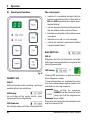
5.1 Control panel functions
The control panel
• consists of a membrane keyboard with six
pressure-sensitive keys (four of them with an
LED, two LED displays and a two-figure sevensegment display.
• controls the printer functions and the print jobs
that are defined via the control software.
• indicates current printer status and processes
in progress.
• indicates errors and / or error messages.
• controls the (optional) automated multilevel
cassette unload station.
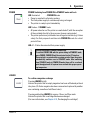
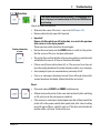
MAG. EMPTY LED
LED off:
Magazines are full or up to that point, no further
slides have been requested from a magazine that
has just been emptied.
LED flashing:
ð
Fig. 42
INK EMPTY LED
LED off:
Sufficient quantity of ink remaining—printing is
possible without any restrictions.
LED flashing:
Ink cartridge will be empty shortly—keep
replacement ink cartridge handy.
LED illuminates:
Ink cartridge empty, no further printing possible.
40
Flashing LED and number on display indicate
which magazine is empty.
If several magazines are emptied at the same
time, the corresponding magazine numbers are
indicated in a recurring sequence.
After refilling the magazine,
LOADED must be pressed to inform
the printer that the magazine has
been refilled.
The printer will resume the interrupted print job
where previously left off.
Instructions for Use V 1.9 RevD - 05/2013
5. Operation
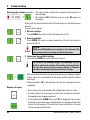
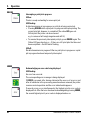
POWER
POWER Switching from POWER ON to STANDBY mode and back
LED illuminated
– POWER ON mode
• Power is supplied to all printer systems.
• The flash power supply is continuously being recharged.
• The printer is ready to print immediately.
LED flashes – STANDBY mode
• All power absorbers of the printer are switched off, with the exception
of those related directly to the processor (power saving mode).
• The printer performs a print head clean at regular intervals (e.g. 4 times
a day). For that purpose it switches into POWER ON mode for a short
period of time.
LED off – Printer disconnected from power supply
Printing is possible in POWER ON mode only.
To activate POWER ON with the printer being in STANDBY mode,
press POWER. POWER ON will be activated via the PC interface.
If no print job is received within a certain period of time, the printer
automatically switches over to STANDBY mode. After switching
from STANDBY mode to POWER ON mode, there will be a reduced
print throughput until all systems have reached their proper operating temperature.
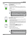
LOADED
To confirm a magazine exchange
Pressing LOADED briefly:
Informs the printer that an empty magazine has been refilled and put back
into place. (Or that a magazine has been removed and replaced by another
one containing cassettes of a different color).
Pressing and holding LOADED for approx. 10 sec. in offline mode:
Informs the printer that a cartridge has been exchanged.
(For more information, see Chapter 4.10, "Exchanging the cartridge").
Leica IP S
41
5.Operation
ONLINE
ERROR
42
Interrupting a print job in progress.
LED on:
Printer is ready and waiting for a new print job.
LED flashing:
A data transmission is in progress or a print job is being carried out.
• Pressing ONLINE while a print job is in progress interrupts printing. The
current print job, however, is completed. The online LED goes out.
At that point the printer can be accessed
e.g. to remove a half-empty magazine and refill it).
• To resume the previously interrupted print job, press ONLINE again. The
Online LED goes back on or—if there are still print jobs that have not
been completed—the LED starts flashing.
LED off:
No data transmission in progress. Either no print job is in progress or a print
job in progress has been temporarily interrupted.
Acknowledging an error code being displayed.
LED flashing:
An error has occurred.
The corresponding error message is being displayed.
If ERROR is pressed after having eliminated the source of an error and
after all obstacles in the processing areas have been removed, the printer
resumes normal operation and the error indication disappears.
If several errors occur simultaneously, the highest priority error code is
displayed first. After that error has been acknowledged by pressing ERROR,
the second highest priority error code is displayed and so on.
Instructions for Use V 1.9 RevD - 05/2013
5. Operation
CLEAN
Cleaning the print head and carrying out a print test
Pressing CLEAN briefly
While a print job is in progress:
• The print job is interrupted. "00" will appear in the display for about 2 s.
• A print head clean is carried out and subsequently the print job is
resumed.
If no print job is in progress:
• A print head clean is performed immediately after "00" has been
displayed.
Pressing the CLEAN button briefly and then releasing it starts a print
head clean (indicated by "00" being displayed). The total duration of
the cleaning procedure can be extended to 10 seconds, if CLEAN is
pressed once more as soon as "00" is displayed. Hold CLEAN for as
long you wish to continue cleaning (max. duration = 10 sec).
Pressing CLEAN for a longer period of time (minimum 3 seconds)
While a print job is in progress:
• The print job is interrupted. Printer switches to offline mode. "00" will
appear in the display for about 2 s.
• A print head clean is performed and subsequently a test print is carried
out on the cassette currently being processed. The printer then remains
in offline mode to enable the user to verify the print quality before resuming the current print job.
If necessary, an additional clean can be performed.
• To resume printing, press ONLINE to return to online mode.
• The print job is resumed where previously left off.
If no print job is in progress:
• The printer switches to offline mode.
• All steps are performed as described above.
When operating continuously, the printer pauses regularly for intermediate print head cleans. Printing is interrupted for approximately
10 seconds, after which time the instrument automatically resumes
operation.
Leica IP S
43
5.Operation
TRAY LOAD
If your printer is not equipped with
an automated unload station, no
function is assigned to this button!
Controls the movement of the lifting table of the
automated unload station (optional)
Place a stack of trays (37) onto the lifting table of
the unload station (Fig. 43).
Any number of trays between 1 and 10 can be
inserted, as the printer counts the trays when
they are inserted.
Once the lifting table has reached its highest
position, the LED in the button starts blinking.
37
Fig. 43
Function:
• The imprinted slides are pushed out of the
printer and onto the uppermost tray.
• At the right end of the tray there is a sensor
(59), which triggers a signal when covered
(Fig. 32). The tray stack is then moved upwards
by one tray.
• Once all trays are full, the instrument emits an
acoustic signal (beep), the LED in the TRAY
LOAD button starts blinking, the stack of trays
can be removed.
Press and hold TRAY LOAD longer than 1 sec:
• The tray stack moves completely into the
unload station, the LED in the button goes off,
the printer switches to ONLINE mode.
• Pending print jobs will be carried out.
When the stack of trays has moved into the
unload station completely or partly:
Press TRAY LOAD briefly
• The stack of trays moves up by one tray.
If TRAY LOAD is pressed and held longer than
one second:
• The stack of trays moves completely out of
the unload station, the LED in the button starts
flashing. Any print job in progress is interrupted.
Every time the printer is switched on,
the stack of trays automatically moves
one tray up, to ensure that the new
print job is started with an empty tray.
59
Be careful about getting near the sensor (59). Any object getting closer than
2 mm to the sensor will trigger a lifting
movement.
Fig. 44
44
Instructions for Use V 1.9 RevD - 05/2013
5. Operation
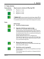
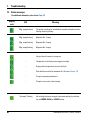
5.2 Display indications
Display indication
Magazine empty (in combination with "Mag. Empty" LED)
1 - Magazine no. 1 empty
2 - Magazine no. 2 empty
3 - Magazine no. 3 empty
If "MANUAL FEED" has been selected in the printer driver settings, "0" will
appear in the display after the print job has been sent. The printer will wait
for an individual specimen slide to be placed in the feeding chute for printing.
Display
Status messages
00 Ink print head cleaning in progress.
11 Temperature in the flash power supply is too high.
Printer is too hot—there will be a short cool-down period.
The print job will be resumed automatically after a short period of time.
To prevent frequent job interruptions due to heat build-up, make sure
the ventilation grids of the printer are unobstructed and keep the
printer away from other heat sources.
Consider operating the printer in an air-conditioned room.
If the temperature does not drop to a value within the allowed range
within 10 minutes, "55" is displayed. Switch the instrumentoff and let
it cool; check ambient temperature.
12 Drying module temperature too low/too high.
If the temperature does not drop to a value within the allowed range
within 6 minutes, "43" is displayed.
13 Flash bulb has reached its maximum life.
The flash lamp has reached the end of its specified service life and
must be replaced.
If this message is ignored, the resistance of subsequent printouts
can be affected.
Leica IP S
45
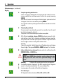
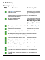
5.Operation
Status messages (continued)
Display
14
Prompt requesting maintenance
If this message is displayed, the instrument will be due for maintenance within the next few weeks. Confirm the prompt pressing
ERROR.
After about 3 weeks the message will be displayed again and will not
disappear from the screen when pressing ERROR.
You can still continue printing but maintenance must be carried out
urgently.
15
Cleaning the print head
Screen prompt requesting the operator to manually clean the print
head (cleaning swab + alcohol).
The printer is off-line. No new print jobs are accepted.
87After the last cartridge change, CLEAN has been pressed to indicate to the printer that a cleaning cartridge has been inserted.
The printer has received a print job but is unable to print because
the cartridge contains cleaning fluid instead of ink.
Remedy:
Cancel the print job. Switch the printer off and back on and change
the cartridge. Then press LOADED or ERROR and wait for 2 minutes.
88Ink cartridge has been changed, device waits for confirmation with
ERROR, CLEAN, or LOADED key.
Caution!
NEVER press LOADED after reinserting an ink cartridge which has
already been used. This could cause permanent damage to the
printer.
ð
Warning:
Problem with cassette ejection from a magazine
81The display consists of two parts: The "8" is a warning that a magazine
ejector is mechanically blocked. The second digit of the
83 message gives the number of the affected magazine.
46
Error messages
All displayed numbers between 20 and 78 and 89 and 93.
Instructions for Use V 1.9 RevD - 05/2013
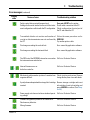
5. Operation
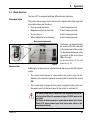
5.3 Alarm functions
The Leica IP S is equipped with two different alarm functions:
Instrument alarm
The printer has a beeper that emits acoustic signals indicating important
instrument states and functions.
• Upon pressing the button:
1 short beeping sound
• Magazine empty/tray stack full:
2 short beeping sounds
• In case of error:
5 short beeping sounds
• When ending the head cleaning:
5 short beeping sounds
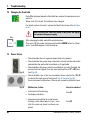
Back panel of instrument
ð
Remote alarm
60
56
Fig. 45
The beeper can be deactivated
by means of the DIL switches
at the back panel of the printer.
To deactivate the beeper, push
the switch at the very bottom
(60) to the right
(in the direction of the red
arrow in Fig. 45).
Additionally, an alarm can be installed outside the room in which the printer
works.
• The remote alarm device is connected to the printer via a 3.5 mm-
diameter jack connector (optional accessory) that is inserted into socket
(56).
• The remote alarm is triggered if no power is supplied to the printer or if
the power switch at the back panel of the printer is switched off.
The remote alarm device connected to the instrument must be rated at less than 100 mA. A maximum voltage of 24 V DC must not be
exceeded.
For details on how to connect a remote alarm device to the Leica
Printer IP S, please contact your local Leica sales office or the
manufacturer directly.
Leica IP S
47
5.Operation
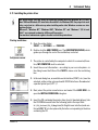
5.4 Printer driver settings
With the Leica IP S slide printer you can print slides from any Windows application allowing
the user to individually configure the printing parameters. The description below refers to Microsoft Wordpad, a program that is part of any Windows installation and therefore available on
all PCs supported by the printer driver. The dialog boxes to be accessed in other programs may
be named differently, but the driver parameters that need to be selected are named identically
in all programs.
Configure the printer in the application that will be used for imprinting the
slides.
1. Open the Print dialog box:
FILE --> PRINT
2. From the list of available printers, select Leica IP S (the name of that
printer was added when installing the printer driver, see Chapter 4.11)
and confirm by pressing the corresponding button.
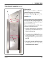
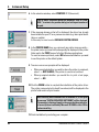
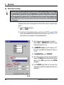
1. First, the page settings must be selected.
Click on FILE --> PAGE SETUP to open the Page
Setup dialog box (Fig. 46).
61
2.In MARGINS (inches), set all margins to "0"";
the print range (61) will change as shown in
Fig. 46.
3.In ORIENTATION, select PORTRAIT.
4. Once the printer has been set up as described
above, the SLIDE format will automatically be
shown in the SIZE input field in the PAPER
dialog box.
5. In the SOURCE input field you can select the
magazine(s) which will supply the slides to be
imprinted.
Fig. 46
48
Instructions for Use V 1.9 RevD - 05/2013
5. Operation
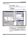
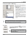
Selectable options in the PAPER --> SOURCE dialog box
When clicking on the Source input field, an alphabetical list of all cassette supply options from
all 6 magazines opens up.
• MANUAL FEED means that individual slides
will be placed onto the chute (12 in Fig. 3) and
imprinted. The printer will not start printing
until the sensor (13 in Fig. 3) reacts.
• Further options are magazines 1 through 6.
If a particular magazine has been selected
as supply source, printing will stop once that
magazine is empty.
• If a group of magazines is selected (such as
F (1|2|3)), printing will continue until the last
magazine of the group selected is empty, i.e.
printing will not stop when just one magazine
is empty.
Fig. 47
Working with magazine groups makes sense for large print jobs requiring more slides than fit
into one magazine or when several magazines have been filled with slides of the same type
(e.g. same color). The magazines will be processed in the indicated order.
Advanced Options
• To select advanced parameters, click on PRINTER... to access the printer
selection menu. Click on PROPERTIES... and ADVANCED... to access the
ADVANCED OPTIONS menu.
The ADVANCED... button does not exist under Windows NT 4.0.
Clicking on PROPERTIES... in Windows NT leads you directly into
the ADVANCED OPTIONS menu.
Leica IP S
49
5.Operation
"ADVANCED OPTIONS" menu
Clicking onto the individual menu items opens up
a pull-down menu to their right, where you can
select the desired parameters.
Any menu items not described here are of no importance for the printer. Therefore, the standard
settings of all menu items not described here
should remain unchanged.
• In the PAPER SIZE menu you select the size of
the imprintable zone of the
slide. Slide must be selected
in this menu, otherwise
printing will not be possible.
• Selectable print head RESOLUTION settings
are 360 and 180 dpi. With
slide surfaces not appropriate for 360 dpi resolution,
printing results will be poor.
For such cassettes, 180 dpi should be selected.
• The PAPER/OUTPUT menu item is important
above all for the multi-cassette unload station.
Fig. 48
• PRINT QUALITY menu item
In this menu, you can select
whether an imprint is to be
applied onto a specimen
slide once (NORMAL) or
twice (OVERSTRIKE).
UPSIDE DOWN imprints are rotated 180°. Here
again, OVERSTRIKE can be selected.
Due to the higher ink consumption and
the substantially poorer printed image,
the OVERSTRIKE setting may not be
used.
50
• SAME TRAY:
slides keep being deposited into a tray until
the tray is full.
• JOB IN NEW TRAY:
each print job starts with a new tray.
• NEW TRAY:
Only for special applications—do not select
this option under standard Windows programs.
When using the manual unloading
system, the values configured in the
PAPER/OUTPUT menu item are not
considered by the device.
Instructions for Use V 1.9 RevD - 05/2013
6. Cleaning and Maintenance
6.1 Cleaning the instrument
Prior to cleaning the instrument, always switch off power supply and unplug the power cord!
When handling cleaning detergents, follow the instructions of the manufacturer and make sure
all laboratory regulations in force in your country are complied with.
To clean the exterior surfaces, use a mild and ph-neutral commercial household cleaner.
You may NOT use: Alcohol, cleaning materials containing alcohol (glass cleaner!), abrasive,
and solvents containing acetone or xylene! The painted surfaces and the control panel of the
instrument are not resistant to xylene or acetone!
No liquid may come into contact with the electrical connections or spill into the interior of the
instrument!
During all cleaning procedures, puncture-resistant gloves and eye protection are to be worn to
protect against injury caused by debris (especially glass).
During vacuuming, direct the air stream generated by the vacuum away from yourself or anyone in the area to avoid possible injury from glass particles.
Slide guiding mechanisms
The IP S needs to be cleaned with a small vacuum daily in the case of heavy use (or weekly
in the case of light use) to remove any debris,
especially glass dust.
Cleaning of the following IP modules signed by
an arrow is of particular importance:
Fig. 49
• Loading station (Fig. 49)
The ejection unit of the magazines, magazine
holders and chute. Always ensure that the
sensor at the end of the chute is clean.
• Transport station (Fig. 50)
Remove dust and debris from the specimen
slide carrier.
Fig. 50
Leica IP S
51
6. Cleaning and Maintenance
Slide guiding mechanisms
• Drying station (Fig. 51)
The chute must be clean.
Caution!
Sensitive electronics components are
located in this area.
Use no liquid in this area!
Fig. 51
Drawer for broken glass
77
78
5
• The drawer for broken glass (77) is located
above the slot for the ink cartridge, behind
the left cover (5). It prevents glass dust and
broken glass from falling into the interior of
the instrument. The drawer can be pulled out
sideways by grasping the black handle (78)
and must be cleaned regularly (Fig. 52).
• Broken glass can easily be removed - use a
brush and remove any glass through the opening in the center of the drawer.
Fig. 52
Automated unload station
• Remove the unload trays; with a brush, remove
dust and debris from guides and ejector.
• The trays themselves can be cleaned with a
household cleaner.
• Do not use any solvents to clean the trays!
• Prior to reinserting them into the instrument,
the trays must be completely dry.
52
Outer surfaces
• Clean the outer surfaces (including those of
the automated cassette unload station) with
a mild detergent and subsequently dry with a
slightly moistened cloth.
• Do not use any solvents for cleaning the outer
surfaces and the lid!
Instructions for Use V 1.9 RevD - 05/2013
6. Cleaning and Maintenance
6.2 Clean print head
Preparing the printer
Once a week or if message "15" is
displayed, the print head must be
cleaned manually.
72
+
• Open the printer lid and then
press buttons CLEAN and
LOADED simultaneously.
• The print head (72) moves
upward to a position approx.
1 cm away from the sealing lip
(Fig. 53).
Fig. 53
• Push the lever (69) upwards, then remove
the red location plate (70) with the sealing lip
(Fig. 54).
• Moisten one of the foam swabs supplied with
the instrument (73) with some alcohol. Be sure
not to use too much alcohol—no alcohol may
drip into the instrument.
70
69
Never use acetone or xylene! Only use
alcohol 95 % or 100 % for cleaning purposes.
Fig. 54
• Carefully insert the swab (89) into the gap
under the print head and apply light pressure upwards (on print head) and move the
foam swab back and forth (Fig. 55) (approx.
10 times!).
This procedure removes dried ink residues.
89
Never rotate the swab—this can damage the nozzle plate of the print head.
Fig. 55
Leica IP S
53
6. Cleaning and Maintenance
Location plate
71
70
•
•
Reinsert the location plate (70).
Caution!
The location plate must be completely dry.
When the cleaning process is finished, press
any key of the control panel to confirm.
• The print head moves back to parking position—message "15" disappears from the
display. The printer is once again ready for
printing.
ð
Fig. 56
• Also clean the location plate (70) and sealing
lip with (clean) alcohol. The sealing lip (71)
must be completely clean—no ink residue
must be left. Check the sealing lip for damage.
Replace the location plate if the sealing lip is
damaged.
If no button is pressed to acknowledge
the end of the cleaning procedure, the
print head will be closed automatically after a few minutes to prevent it
from drying out.
• However, the message "15" remains in the
display, as the instrument assumes that the
cleaning has not been carried out.
6.3 General maintenance
Only authorized and qualified Leica service personnel may repair
the instrument and access the instrument's internal components.
The Leica IP S printer is virtually maintenance-free.
To ensure smooth operation of the instrument over many years we do recommend the following:
• Clean the instrument thoroughly on a daily basis.
• Regularly remove dust from the ventilation slots on the back of the instrument using a brush or a small vacuum cleaner.
• Have the instrument inspected once per year by a qualified service engineer authorized by Leica.
• At the end of the warranty period, enter into a service contract. For more
information, please contact your local Leica technical service center.
54
Instructions for Use V 1.9 RevD - 05/2013
6. Cleaning and Maintenance
6.4 Storing the printer
If the printer is not used for a long period of time (up to three months), the
following instructions are to be followed.
Important!
• If the instrument remains connected to the power supply with the power
on, the ink cartridge can remain in the printer up to its expiration date.
• The print head drying out is prevented, because the printer regularly
rinses the print head.
• You must absolutely ensure that the ink cartridge is switched out according to its expiration date.
If the instrument is switched off and separated from the power supply, the
following is to be done:
A printer may be stored for a maximum of three months after following the procedure described below. Storing the printer for longer periods may result in damage to the print head.
Instructions on the storage location
• Open the cover plate (5) on the left side of
the instrument by pressing its top left corner
(see Fig. 31). Then push the security latch (86)
forward (Fig. 57).
87
86
88
• Pull the ink cartridge (66) approx. 3 cm out
of the instrument so that the "Ink Empty" LED
lights.
66
Fig. 57
The ink cartridge cannot be used in
another printer, because the ink level
information is stored in the printer
itself.
Leica IP S
• Screw the red cap (87) to the shutter (88),
close it securely and take the ink cartridge
out completely.
• Store the ink cartridge in a horizontal position
in a sealed container.
55
6. Cleaning and Maintenance
Instructions for storage (continued)
• Push a (new) cleaning cartridge as far as it
will go into the shaft (Fig. 58).
64
• Unscrew the red cap (85) one turn and slide
the cartridge fully home.
• Push the security latch (86, Fig. 57) back in
front of the cartridge.
85
Fig. 58
ð
• The "Ink Empty" LED will go out and "88" will
appear on the display.
ð
• Press CLEAN to rinse the print head; "00" will
appear on the display. The display will go out
when the cleaning process is complete.
The cleaning process with solvent
takes approx. 3.5 minutes.
72
+
• Open the hood of the printer
(4 in Fig. 31), then press the
CLEAN and LOADED keys simultaneously.
• The print head (72) moves upward to a position approx. 1 cm
(1/2 inch) away from the sealing
lip (Fig. 59).
69
• Push the small lever (69, Fig. 59) upwards
under the print head.
Fig. 59
56
Instructions for Use V 1.9 RevD - 05/2013
6. Cleaning and Maintenance
• Then pull out the location plate (70), (Fig. 60).
Instructions for storage (continued)
• Clean the print head with a foam swab, as described in Chap. 6.2, "Cleaning the print head"
(see also Fig. 61).
70
Always use the cleaning swab for the
print head once only. Never rotate the
swab—this can damage the nozzle
plate of the print head.
Fig. 60
89
73
• After cleaning the print head,
insert a new transport plate
(73).
• Push the small lever (69,
Fig. 59) back down into its
original position.
• Reclose the lid of the printer
and press any key; the print
head moves back into the
rest (park) position.
• Screw the red cap (85,
Fig. 58) to the shutter, close
it securely, and take the ink
cartridge out completely.
Fig. 61
Important!
Turn the printer off and disconnect it from the power supply at this point to prevent damage to
the print head.
Never use a cleaning cartridge together with a location plate (70)!
Do not reinstall a used transport plate (73), as it will no longer completely seal the print head.
Leica IP S
57
6. Cleaning and Maintenance
Instructions for storage (continued)
• Likewise, clean the removed removable disk
(70) with the sealing lip with (clean) alcohol
and a cleaning swab (89) (Fig. 62).
70
71
• The sealing lip (71) must be completely free
of ink residue. Check the sealing lip for damage. Do not reuse a replacement plate with a
damaged sealing lip.
89
Fig. 62
• Clean the instrument completely, as described
in Chap. 6.1.
Transporting the printer
If the printer is to be shipped, the storage instructions described above
are to be carried out completely. Then, additionally make the following
preparations:
• Open the hood (4, Fig. 31) of the printer and loosen the screw of the flash
cover.
• Afterward, take out the flash bulb (refer to Chapter 4.7)
• Close the flash cover and the hood.
• Use original packaging and securely screw the printer to the baseplate
(see unpacking instructions).
• Reinsert the transport anchor (27) (see Fig. 12) and secure the hood with
adhesive tape.
• Make sure that the instrument is only transported upright.
58
Instructions for Use V 1.9 RevD - 05/2013
7. Troubleshooting
7.1Malfunctions
If the printer malfunctions during printing, a corresponding error
code is displayed and simultaneously the LED in the ERROR button
starts flashing.
+
How to eliminate the problem:
• Determine the cause of the error—see error list (Chapter 7.3).
• Remove obstruction(s); open lid if required.
Confirm elimination
of error
• Important!
Remove all slides which are still in the chute, in or next to the specimen
slide carrier or in the drying module!
These specimen slides should not be used again.
• Reclose the hood and press the ERROR button to confirm to the printer
that the source of the error has been eliminated.
• The printer then verifies whether all processing paths are unobstructed
and whether the source of the error has been eliminated.
• If there are still some obstructions left, or if the source of error has not
been thoroughly eliminated, the printer displays another error message.
• Interrupted print jobs are resumed where previously left off.
• If an error message is displayed several times although all possible
causes have been eliminated, a Reset should be carried out.
Reset:
• Press and release LOADED and ERROR simultaneously.
+
• A Reset restores the printer to the same state as directly after switching
on. All print jobs in the print queue are deleted.
• If the same error continues to be displayed even after a Reset, switch the
printer off via the power switch (back panel) and, after a short waiting
period of approx. 30 sec., switch it back on. If this does not eliminate the
problem either, call Leica Technical Service.
Leica IP S
59
7.Troubleshooting
7.2 Status messages
(For additional information, refer also to Chap. 5.2)
Display
code
"Mag. empty flashing"
The printer is waiting for an individual cassette to be placed in the
feeding chute for printing.
"Mag. empty flashing"
Magazine No. 1 empty
"Mag. empty flashing"
Magazine No. 2 empty
"Mag. empty flashing"
Magazine No. 3 empty
–
Ink print head cleaning is in progress.
–
Temperature in the flash power supply is too high.
–
Drying module temperature too low / too high.
–
Flash bulb has reached its maximum life. (See also Chapter 7.4)
–
Prompt requesting maintenance.
–
Prompt to carry out a head cleaning.
"Ink empty" flashing
60
Meaning
LED
Ink cartridge has been changed; instrument waiting for confirmation via ERROR, CLEAN, or LOADED button.
Instructions for Use V 1.9 RevD - 05/2013
7. Troubleshooting
7.3 Error messages
Display
code
Source of error
Troubleshooting solution
Magazine output mechanically blocked.
Remove the cause of the blockage.
Faulty ejection of a slide. Magazine output blocked.
Remove the slide.
Transfer of a slide from the chute to the specimen Remove the slide.
slide carrier failed. Horizontal motor either incorrectly
positioned or mechanically blocked.
Slide is stuck in the feeding chute.
Remove the slide.
Horizontal drive is mechanically blocked.
Remove the slide.
Vertical drive is mechanically blocked.
Remove the slide.
Rotational motion is mechanically blocked.
Remove the slide.
Slide not correctly clamped in specimen slide carrier. Remove the slide from the specimen
Slide did leave the feeding chute but did not reach the slide carrier.
specimen slide carrier.
Slide did not leave the specimen slide carrier or was Remove the slide from the specimen
still located in the specimen slide carrier during initial- slide carrier.
ization.
The ink print head is getting too hot.
Switch instrument off and let it cool off.
Ambient temperature too high or electronics defective. The instrument remains disabled until
the print head has cooled down to a
temperature value within the permissible range.
Check ambient temperature.
No or incorrect voltage at ink print head.
Leica IP S
Call Leica Technical Service.
61
7.Troubleshooting
Error messages (continued)
Display
code
Source of error
Cover (4 in Fig. 2) not closed properly.
Safety switch triggered.
Troubleshooting solution
Ensure that the cover is not blocked,
e.g. by the manual unload station.
Close cover completely.
Flash standby state not reached within the prescribed Call Leica Technical Service.
time. Charging electronics defective.
No flash or flash duration too short.
Flash bulb dirty or defective.
Check whether flash bulb works – to do
so, observe the stray light on the cover.
Never open the cover to check whether a flash is triggered!
No flash --> install a new flash bulb.
See Chapter 4.7.
The temperature in the drying module is not within the Carry out a RESET. See Chapter 7.1.
permissible temperature range.
Unload station mechanically blocked.
Remove the cause of the blockage.
Heater fan not running or running too slowly.
Call Leica Technical Service.
No slide in the drying module for flashing. Slide left the Remove the specimen slide.
specimen slide carrier, but did not reach the drying
module.
Slide not successfully ejected from drying module.
Remove the specimen slide.
Slide in the drying module during initialization or prior to Remove the cause of the blockage.
a print job being carried out.
The flap of the drying module either does not close or Remove the cause of the blockage.
does not open; flap is blocked (e.g. by a slide).
Lifting table end sensor does not switch.
Call Leica Technical Service.
Lifting table position sensor does not switch during Call Leica Technical Service.
positioning.
Flash power supply: Overtemperature for more than Call Leica Technical Service.
10 minutes.
62
Instructions for Use V 1.9 RevD - 05/2013
7. Troubleshooting
Error messages (continued)
Display
code
Source of error
Troubleshooting solution
Faulty control data received (program bug)
Carry out a RESET on the printer.
Settings for the serial interface incorrect or the instru- Check cable connection to the PC.
ment configuration conflicts with the PC configuration. Check configuration of serial port of
the PC and reboot the PC.
Transmitted data do not contain confirmation of Follow the same procedure as for
receipt or data transmission was not confirmed by ERROR 60.
the PC.
Try another printer cable.
Print image exceeding the vertical limit.
Error caused by application software.
Print image exceeding the horizontal limit.
Error caused by application software.
The CRC test of the EEPROM returned an error when Call Leica Technical Service.
the instrument was switched on.
...
Internal firmware error or
defective controller.
Call Leica Technical Service.
...
Mechanical problem makes ejection of cassettes from Check ejection mechanism. Remove
magazine difficult.
foreign bodies, then clean with brush.
A print job was attempted with a storage fluid cartridge Remove storage cartridge and insert
inserted.
ink cartridge. Insert ink cartridge and
press LOADED to confirm. (See Chapter 4.9)
Power supply unit does not achieve standard operat- Call Leica Technical Service.
ing voltage.
Leica IP S
Firmware only partially loaded or not loaded at all.
Flash memory defective.
Call Leica Technical Service.
Wrong firmware.
Call Leica Technical Service.
63
7.Troubleshooting
7.4 Changing the flash bulb
Code 13 is displayed when the flash bulb has reached its maximum serviceable life.
When code 13 is issued, the bulb has to be changed.
For details on how to insert / replace the flash bulb, please refer to Chapter 4.7.
Before replacing the flash bulb, switch off the printer and unplug
the instrument from power supply.
10 s
After changing the bulb, switch the printer back on.
Then go to Off-line mode and press and hold the ERROR button for 10 seconds - code 13 disappears from the display.
ð
7.5 Power failure
Fig. 63
Fig. 64
• Check whether there is a general power failure (no power).
• Check whether the power plug is inserted correctly into the wall outlet
and whether the wall outlet is switched on, if applicable.
• Check whether the power switch is switched on correctly. Possibly, the
primary fuse has tripped. If so, the main switch will be in "0" = OFF position (Fig. 63).
• Check whether one of the two secondary fuses is defective. (F1, F2
located at the back panel of instrument, Fig. 64, see also Fig. 65).
Some instrument malfunctions / failures are caused by defective fuses.
Malfunction / failure
Fuse to be checked
• Instrument not functioning.
• No display indication.
Fuse F1
• Instrument not working at normal speed.
Printing a slide takes approx. 8 sec., even
after the warm-up phase has been completed.
64
Fuse F2
Instructions for Use V 1.9 RevD - 05/2013
7. Troubleshooting
7.6 Replacing the fuses
Before replacing a fuse, always switch the instrument off and unplug from power supply.
Defective fuses may be replaced only with the replacement fuses supplied together with the
instrument.
Replacing the fuses
92
90
90
91
Fig. 65
Fig. 66
• Insert a screwdriver (91) into the slot in fuse
holder (90); push slightly inwards and at the
same time rotate the screwdriver 1/4 turn to
the left.
• The fuse holder is released and can be
removed.
Leica IP S
• Remove the defective fuse (92) from the fuse
holder (90) and insert the correct type replacement fuse.
• Reinsert the fuse holder together with the fuse.
Insert the screwdriver into the slot in the fuse
holder, push slightly inwards and at the same
time rotate the fuse holder 1/4 turn to the right.
65
8. Warranty and Service
Warranty
Leica Biosystems Nussloch GmbH guarantees that the contractual product
delivered has been subjected to a comprehensive quality control procedure based on the Leica in-house testing standards, and that the product
is faultless and complies with all technical specifications and/or agreed
characteristics warranted.
The scope of the warranty is based on the content of the concluded agreement. The warranty terms of your Leica sales organization or the organization from which you have purchased the contractual product shall apply
exclusively.
Technical service information
If you require technical service or replacement parts, please contact your
Leica sales representative or dealer who sold the product.
Please provide the following information:
•
•
•
•
Model name and serial number of the instrument.
Location of the instrument and name of the person to contact.
Reason for the service call.
Date of delivery.
Shutdown and disposal of the instrument
The instrument or parts of the instrument must be disposed of in compliance
with the local laws.
66
Instructions for Use V 1.9 RevD - 05/2013
www.LeicaBiosystems.com
Leica Biosystems Nussloch GmbH
Heidelberger Straße 17-19
D- 69226 Nussloch
Tel.: +49 - (0) 6224 - 143 0
Fax: +49 - (0) 6224 - 143 268
Web: www.LeicaBiosystems.com