1
`bob`=P
pÉêîáÅÉ=j~åì~ä
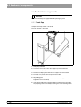
Additional requirements:
•
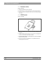
Spare parts list
Order No. 58 62 581
•
•
Circuit diagrams CEREC 3 / CEREC Scan
Acquisition unit:
Order No. 58 35 710
Milling unit:
Order No. 58 35 728
Tools
– Hexagonal screwdriver (90° offset): Sizes 1.5; 2; 2.5; 4; 6
– Fork wrench, sizes 5.5; 8; 10; 14
– Torque screw driver, sizes 5, 6, 20, 25, 40
– Philips-head screw driver Size 1
– Slot screw driver, insulated, Size 2, 3
– Socket wrench 8mm
– Cutting pliers
– Special tool for monitor nut
– Special tool for locking button: Order No.: 59 08 947
•
Accessories
– Digital multimeter, accuracy class: 1
– Soldering tool for repairing cables
– Side cutting pliers
– Cable ties
– Teflon tape
– PS2 mouse (recommended)
– PS2 keyboard (recommended)
– 3.5” disk
– Calibration piece and pins (recommended)
– Fuses (recommended):
F1/F2 (2 pcs.)
5AT,
Order No.: 20 33 111
F1/F2 (2 pcs) for acquisition unit starting with Ser. No.: 3300
6,3 AT, Order No.: 10 77 452
F3
1.25AL Order No.: 59 15 181
F4
2AT
Order No.: 10 80 522
General 1
Service Software 2
Trouble Shooting: Milling Unit 3
Trouble shooting: Acquisition Unit 4
Settings 5
Acquisition Unit: Repairs 6
Milling Unit: Repairs 7
Installing Software 8
List of Contents
1
General ................................................................................................................................... 1-1
1.1
2
Service Software .................................................................................................................... 2-1
2.1
2.2
2.3
3
General Notes .............................................................................................................. 2-3
Basic Structure of Test Dialogs .................................................................................... 2-5
Individual Test Points ................................................................................................. 2-10
Trouble Shooting: Milling Unit................................................................................................. 3-1
3.1
3.2
3.3
3.4
3.5
3.6
3.7
3.8
3.9
3.10
3.11
4
General Notes .............................................................................................................. 1-3
Device cannot be switched ON. Green LED (Ready for operation) not illuminated ... 3-5
No connection to PC / acquisition unit. Software cannot be installed .......................... 3-7
No air pressure............................................................................................................. 3-9
Fan not running. Unit shuts down completely after a short time ................................ 3-11
Water pump: Pressure too low ................................................................................... 3-13
Defective light barrier ................................................................................................. 3-15
Door switch. Please close milling chamber door........................................................ 3-17
Motor locking positions: Problems changing grinders ................................................ 3-19
Stepping motors (milling unit). Loss of steps.............................................................. 3-21
Touch errors ............................................................................................................... 3-23
Trouble shooting. Defective CCP board..................................................................... 3-25
Trouble shooting: Acquisition Unit .......................................................................................... 4-1
4.1
4.2
4.3
4.4
4.5
4.6
4.7
4.8
4.9
4.10
4.11
4.12
4.13
4.14
4.15
4.16
4.17
4.18
4.19
4.20
System cannot be switched ON ................................................................................... 4-7
PC not booting properly I.............................................................................................. 4-9
PC not booting properly II........................................................................................... 4-11
PC does not respond during switch-on, PC power supply does not start .................. 4-12
Further PC faults ........................................................................................................ 4-14
Monitor image flickering ............................................................................................. 4-15
No monitor display...................................................................................................... 4-17
Incorrect monitor display format size.......................................................................... 4-19
Monitor: Color shade/gray scale is too weak.............................................................. 4-21
Trackball not functioning ............................................................................................ 4-23
Trackball buttons not functioning................................................................................ 4-25
Pedal not functioning.................................................................................................. 4-27
Keyboard not functioning /defective ........................................................................... 4-29
No camera image ....................................................................................................... 4-31
Incorrect measuring sensor setting ............................................................................ 4-33
Camera calibration: messages................................................................................... 4-35
Interference at radio interface .................................................................................... 4-37
No sound or sound level too low ................................................................................ 4-41
No Sirocam camera image......................................................................................... 4-43
Sirocam camera image interference .......................................................................... 4-45
58 35 694 D 3344
D 3344.076.01.05.02 04.2012
V
List of Contents
4.21 SIROCAM camera: Incorrect image settings .............................................................. 4-47
4.22 Digital X-ray problems ................................................................................................. 4-49
5
Settings....................................................................................................................................5-1
5.1
5.2
5.3
5.4
5.5
6
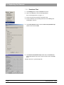
Acquisition Unit: Network Installation ............................................................................ 8-3
How to install an MO drive .......................................................................................... 8-25
Re-test .....................................................................................................................................9-1
9.1
9.2
9.3
9.4
VI
Milling Unit: General Activities....................................................................................... 7-3
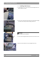
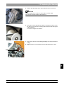
Replacing the Scanner.................................................................................................. 7-5
Replacing the Drive and/or Motor ............................................................................... 7-11
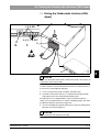
Checking / Adjusting Stop positions............................................................................ 7-13
Stepping Motors: Replacing / Adjustment ................................................................... 7-15
Installing Software ...................................................................................................................8-1
8.1
8.2
9
Electrical and Electromechanical Components ............................................................. 6-4
Mechanical components ............................................................................................. 6-30
Milling Unit: Repairs.................................................................................................................7-1
7.1
7.2
7.3
7.4
7.5
8
5-3
5-4
5-5
5-8
5-9
Acquisition Unit: Repairs .........................................................................................................6-1
6.1
6.2
7
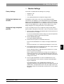
Monitor Settings ............................................................................................................
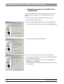
Calibrating the 3D camera ............................................................................................
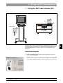
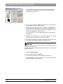
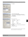
Pairing the DECT-radio interface (EU) ..........................................................................
Replacing a module of the DECT radio interface (EU) .................................................
Pairing the Futaba radio interface (USA/Japan) ...........................................................
When is the re-test carried out? ....................................................................................
Description of device type .............................................................................................
To be carried out on completion of the test...................................................................
What the test steps involve ...........................................................................................
9-1
9-1
9-1
9-1
58 35 694 D 3344
D 3344.076.01.05.02 04.2012
1 General
CEREC 3
List of Contents
General
List of Contents
1.1
1-2
General Notes .....................................................................................................................
1-3
58 35 694 D 3344
D 3344.076.01.05.02 04.2012
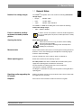
1.1 General Notes
Nominal line voltage ranges
The CEREC® 3 acquisition unit can be used in the following nominal line
voltage ranges:
•
Europe
230VAC / 50Hz
•
USA
115VAC / 60Hz
•
Japan
100VAC / 50Hz and 60Hz
The CEREC 3 / CEREC Scan milling unit can be used in the following
nominal line voltage ranges:
•
Faults in electronic medical
equipment caused by mobile
phones
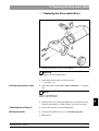
Opening the device
100V – 230VAC; 50/60Hz
In order to ensure safe operation of electronic medical equipment,
the use of mobile phones in practices and hospital areas is strictly
prohibited.
When opening the device:
Please observe the necessary precautions when handling
printed circuit boards (ESD).
Touch a ground point to discharge static electricity before
handling any components.
Measurements
Always switch OFF the device before connecting the measuring instrument.
Select the correct current/voltage type and adjust the measuring range to
match the expected readings.
Perform continuity tests only on devices which are switched off.
When replacing parts
Switch OFF the device before replacing any parts.
For safety reasons the device should be disconnected from the power
supply when replacing parts around the line transformer.
The item numbers for ordering spare parts can be found in the
spare parts list, Order No. 58 62 581.
The diagrams contained in the spare parts list provide a useful guide when
replacing parts.
Repairing and/or upgrading the
PC drawer
Replace the broken warranty seal on the bottom side of the PC drawer with
the supplied seal of conformity.
Disposal
Please observe the instructions found in the relevant user guide.
58 35 694 D 3344
D 3344.076.01.05.02
04.2012
1-3
1.1
1.1 General Notes
2 Service Software
CEREC 3
List of Contents
Service Software
List of Contents
2.1
2.2
2.3
2-2
General Notes ..................................................................................................................... 2-3
Basic Structure of Test Dialogs ........................................................................................... 2-5
Individual Test Points .......................................................................................................... 2-10
58 35 694 D 3344
D 3344.076.01.05.02 04.2012
2.1 General Notes
2.1 General Notes
Service Software Log File
Requirement for all tests:
•
PC / acquisition unit are switched on and ready for operation.
•
PC / acquisition unit and milling unit are interconnected (per interface cable or radio link)
•
The software has been loaded for the milling unit (see Operating Instructions for Milling Unit/Milling Unit Scan, Switching the units on, Initial
start-up).
•
The door of the milling chamber must remain closed as long as any motors or the water pump are running.
If the door of the milling chamber is opened during the test, all motors and
the water pump will switch off immediately (same function as pressing the
Stop button).
•
The tools (burs) must be installed already during operation of the water
pump.
•
During operation of the water pump, the air pump must always be running
to protect the gearing against water damage, i.e. the air pump is started
first. If the air pressure switch detects no air pressure, an error message
will appear and the test can not be performed.
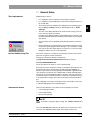
The service software is a component of the product software. This software
generates a log file for all tests performed.
This log file is located on delivery in the directory
c:\programme\Cerec\System\Service\Protocols and is named
Test file_XXXXXXXXXXXX.TXT
The Xs here denote the serial no. of the controller board.
Each time the service software is started, a confirmation query appears asking whether this file (if it already exists) should be deleted. If NO (do not
delete) is selected, the tests subsequently performed will be appended to the
ones previously saved. Each test is labeled with a starting and ending date.
The test file can be viewed with the editor at any time. If the user exits from a
test without saving it, he will be asked if he really wants to quit without saving.
If Yes (Quit without saving) is then selected, the data just measured will be
lost.
After completing a test section, the log file must be saved under a new name
to a diskette belonging to the corresponding unit.
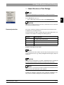
Assessment scores
There are three different scores which can be assigned to test results:
•
Passed fully (green label)
•
Passed (yellow label)
•
Not passed (red label)
i
NOTE
These assessment categories apply starting with software version V1.1
R600
The score Passed (yellow label) may be irrelevant for a specific test. In this
case n.a. (not applicable) will be written to the log file for this score.
58 35 694 D 3344
D 3344.076.01.05.02
04.2012
2-3
2.1
Test requirements
2.1 General Notes
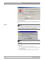
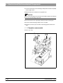
CAUTION
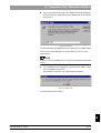
To ensure trouble-free operation of the system, all test results should be labeled "Passed fully".
If the test results are marked "Passed", uncritical changes have occurred at
this point of time.
If the test results are labeled "Not passed", you must find and correct the
fault(s)
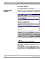
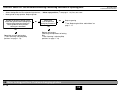
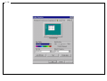
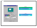
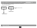
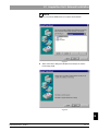
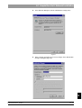
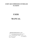
Example of test protocol:
Path: c:\programme\Cerec\System\Service\Protocols
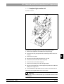
i
NOTE
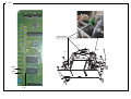
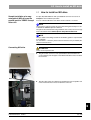
If the milling unit housing is left open, the temperature switch on the CC PC
board may cut out after a short time (T>90°C). The cooling fan can work properly only with the cover closed.
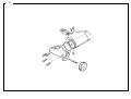
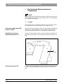
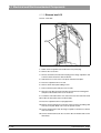
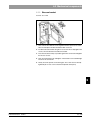
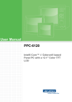
Overview of gearing unit:
Gearing 3
Gearing 1
Gearing 2
(without function)
2-4
58 35 694 D 3344
D 3344.076.01.05.02 04.2012
2.2 Basic Structure of Test Dialogs
2.2 Basic Structure of Test Dialogs
i
NOTE
For a functional description of the menu items, see the user’s manual.
•
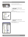
2.2
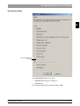
Via the Service menu you can ...
select a wide range of Service functions with Settings/Service...
CAUTION
The Service functions may be used only by authorized service technicians
who have been trained by Sirona.
Password protection
The service software test dialogs are protected by a password to prevent
manipulations by unauthorized users.
The password has four digits. It changes daily and is generated from the system date of the computer according to the following scheme:
Password
number
Generated from
1
2. number of the current month
2
1. number of the current month
3
2. number of the current day
4
1. number of the current day
Example: 24.05.2001 becomes 5042
i
NOTE
Since the password is thus valid for only one day, it may be passed on to the
user in exceptional cases, e.g. when providing him with emergency help over
the phone.
CAUTION
The password should always be treated confidentially. Before entering the
password, always determine the date as inconspicuously as possible.
i
NOTE
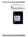
If you enter the correct password, and the commands are nevertheless not enabled, first check the system date of the computer.
The dialog for setting the system time can be called up in all Windows operating systems by double-clicking the time displayed in the status line.
58 35 694 D 3344
D 3344.076.01.05.02
04.2012
2-5
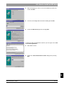
2.2 Basic Structure of Test Dialogs
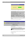
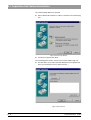
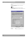
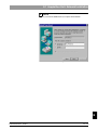
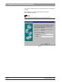
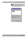
Now enter the password.
If you confirm this Service dialog with Yes, the Test selection dialog box will
open.
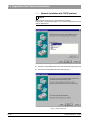
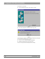
Log file
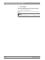
i
NOTE
If a log file named after the milling unit already exists at the time of the program
start, a confirmation query will appear asking if the data from the new test run
should be appended to the existing file or it should be deleted first.
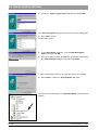
i
NOTE
If the display "…0000.txt" appears, this means that there is no connection to
the milling unit.
Possible causes:
2-6
•
The CEREC 3 program has been started more than once
•
There is no (cable or radio-link) connection between the milling unit and
the acquisition unit/PC
•
The software download to the milling unit has not been completed.
58 35 694 D 3344
D 3344.076.01.05.02 04.2012
2.2 Basic Structure of Test Dialogs
2.2
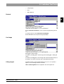
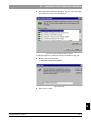
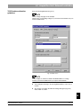
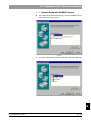
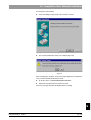
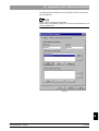
Test selection dialog
Tests performed only at
the factory
In the Test selection dialog you can select …
•
a Total test (default selection on delivery) or
•
an individual test.
The selected test dialog is then opened by clicking on OK.
58 35 694 D 3344
D 3344.076.01.05.02
04.2012
2-7
2.2 Basic Structure of Test Dialogs
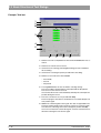
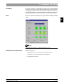
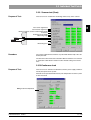
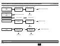
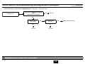
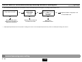
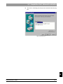
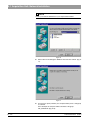
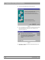
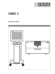
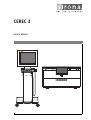
Example: Total test
1
2
10
3
4
5
6
7
9
8
1. Number of test runs completed since the last time the Start button was actuated.
2. Status bar for current state of test run.
3. Check boxes for selecting (activating/deactivating) the tests available in
this test dialog.
4. Check box for selecting the options possible in this test dialog.
5. Number of test results since the last Start:
– Passed fully
– Passed
– Not passed
6. Pressing Start initiates the test run with the selecting settings.
The test run will be repeated until it is interrupted with the Stop button.
The test run counter is then reset to 0.
Once started, the test run can be halted only with Stop. No other inputs are
possible during the test run.
7. The test is canceled as soon as possible with Stop.
The test in progress at the time of cancellation is not counted. All inputs are
now possible again.
8. Save stores all existing data to the log file. The data are appended to the
previously existing log file (if the current test run has not yet been saved).
If no data exist, a message to that effect will appear (confirm with OK).
Once a test run has been saved to the log file, a new test run must be started before selecting the save function again.
2-8
58 35 694 D 3344
D 3344.076.01.05.02 04.2012
2.2 Basic Structure of Test Dialogs
2.2
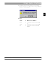
9. Press Back to quit the test dialog and return to the service dialog.
If any data exist and have not yet been saved, you will be queried whether
or not the test data should be saved.
10. Result:
58 35 694 D 3344
D 3344.076.01.05.02
04.2012
• No color
=>
No measurement available yet
• Green
=>
Measurement shows that test was Passed
fully
• Yellow
=>
Measurement shows that test was Passed
• Red
=>
Measurement shows that test was Not
passed
2-9
2.3 Individual Test Points
2.3 Individual Test Points
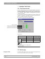
2.3.1 Serial Communication
The test is primarily used to measure the speed and quality of data transmission. This is especially important if the system is not operated through the
standard line (RS-232 max. 10 m), but via other types of connections instead
e.g. an infrared link, a DECT coupling or over longer distances via interface
converters e.g. RS-422.
The transmission time between the beginning of transmission and the end of
reception is calculated for a specific data record on the PC. A test run comprises one complete transmission in both directions.
The values thus measured are then saved to the log file.
Result of last test run
Minimum measured transmission time
Average measured transmission time
Maximum measured transmission time
Typical values:
COM1
Baud rate: 115200
Cable
Radio
i
COM1
Baud rate: 19200
400-500ms
Europe
USA/Japan
–
600-750ms
–
–
2-3s
NOTE
The limiting values and color coding refer to a
baud rate of 115200.
2.3.2 Media supply
Purpose of Test:
2 - 10
To check the media supply (air, water, fan) for proper functioning and test the
pressure switches and the run-up time of the pump.
58 35 694 D 3344
D 3344.076.01.05.02 04.2012
2.3 Individual Test Points
The pumps and the fan are switched on by nominal select control depending
on selection. The motor currents and the condition of the pressure switches
are registered. The points of time when the pressure detectors respond are
measured. After approx. 5 seconds the pumps are switched off and the time
required until the pressure switch responds is measured and evaluated.
Save
Save stores the measured values to the log file under the heading of Media
supply.
2.3
Procedure
i
NOTE
The limiting values apply to a completely filled water circuit.
Deviations of measurements
58 35 694 D 3344
D 3344.076.01.05.02
04.2012
Deviations may occur:
•
During the first test run (if any air is still in the water circuit)
•
If the amount of water in the water tank is insufficient
•
After filling the water tank.
2 - 11
2.3 Individual Test Points
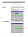
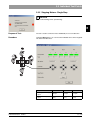
2.3.3 Light Barriers, Door Switch, Temperature
Sensor and Motor Stop Positions
Purpose of Test:
This test serves to evaluate the safe functioning of the light barriers and check
the door switch, the temperature sensor and the motor stop positions.
Light Barriers
When the end position is located, the slot of the gear is measured via the
width and height at which the stepping motor positions are registered with the
flanks.
The light barriers to be tested can be selected in all variations. If no light barrier is selected, the Start button is not active.
Default setting: All light barriers selected.
Door Switch/Control Keys
2 - 12
The current state of the door switch and control keys can be checked via a
status bar display.
58 35 694 D 3344
D 3344.076.01.05.02 04.2012
2.3 Individual Test Points
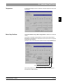
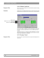
A temperature display has been realized to check the temperature of the milling machine.
Motor Stop Positions
In the Test selection dialog, Motor stop positions is defined as the default
setting.
2.3
Temperature
The motors are moved to these positions to test the motor stop positions.
Depending on which button is selected, the motors move to the corresponding position and stop there.
The motors can be reset to their home positions by pressing the Home button.
Stop position for tool change
Aux. position for replacing components
If the home position can not be reached or lost steps occur during motor
movement, this will be reported.
58 35 694 D 3344
D 3344.076.01.05.02
04.2012
2 - 13
2.3 Individual Test Points
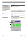
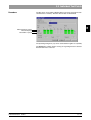
2.3.4 Stepping Motor Test
CAUTION
Observe the warnings in the Testpiece dialog.
Purpose of Test:
This test serves to evaluate the functioning of the stepping motors. The stepping motors are tested and evaluated for this purpose. The evaluation is made
based on a factor for the reserve capacity of each stepping motor. In addition,
this test can also be used for installation and adjustment purposes as well as
to break in the milling machine.
Procedure
It is possible to individually trigger and test the stepping motors in various
combinations.
The stepping motors are run at various speed settings via an acceleration
table and the resulting step losses are measured. The number of step loss
events is then registered and evaluated. Finally, a reserve capacity is
assigned to each motor based on this data.
Display of Test Results
In order to satisfy different requirements for adjustment and testing purposes,
this test also offers the option of choosing between data summation and display of the results for individual test runs.
Rotation
Longit. movement
Standard
Refers to Stage 2
2 - 14
58 35 694 D 3344
D 3344.076.01.05.02 04.2012
2.3 Individual Test Points
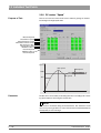
2.3.5 Stepping Motors - Single Step
CAUTION
2.3
Observe the warnings in the opened dialog.
Purpose of Test:
The test is used to control the motors individually in case of malfunction.
Procedure
Using the Move buttons, you can move the individual motors in the longitudinal and rotation directions.
Grind
58 35 694 D 3344
D 3344.076.01.05.02
04.2012
Block
Mill
One longitudinal step (L)
equals
12.5µm
12.5µm
12.5µm
One rotational step (R)
equals
approx. 0.04°
(2.5’)
approx. 0.13°
(7.7’)
approx. 0.04°
(2.5’)
2 - 15
2.3 Individual Test Points
2.3.6 DC Motors "Inlet/Load"
Purpose of Test:
This test serves to run in the DC motors and check them for proper functioning
under continuous load.
Procedure
The DC motors are tested through operation at a constant current. The resulting speed provides an indication of the running resistance of the gearing units.
Motor current
Always 0, since motor current preset
Actual speed
Measure of speed fluctuation
The two motors (Motor 1 and Motor 3) can be selected together or separately.
If no motor is selected, the Start button is not active. Default: Both motors
selected.
Test Run: The test runs in an endless loop until the Stop button is actuated.
The current measured values are displayed. A test run consists of one part
run time and one part pause for each motor.
2.3.7 DC motors "Touch"
Purpose of Test:
2 - 16
This test is used to check the two DC motors for proper functioning in the Lowspeed mode.
58 35 694 D 3344
D 3344.076.01.05.02 04.2012
2.3 Individual Test Points
Procedure
2.3
The DC motors are tested by adjusting them to the touch speed (in the relevant directions of rotation). Then the relevant data are determined.
Measured motor current
Measured speed
Fluctuation of speed
The possible gearing units (1,3) can be selected either together or separately.
The Start button remains inactive as long as no gearing has been selected.
Default: Both motors selected.
58 35 694 D 3344
D 3344.076.01.05.02
04.2012
2 - 17
2.3 Individual Test Points
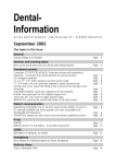
2.3.8 DC motors ”Speed”
Purpose of Test:
This test is used to check the two DC motors and their gearings for flawless
functioning in the High-speed mode.
Measured speed
Fluctuation of speed
Measured motor current
Fluctuation of motor current
Run-up time to 100%
Run-up time to 70%
Maximum value of
measured speed
Minimum value of
measured speed
n
(r.p.m.)
Max. speed
RMS speed
100%
Min. speed
70%
t (s)
Procedure
The DC motors are tested by accelerating them from a standing start to working speed and then measuring the relevant data.
i
NOTE
The current is monitored during all measurements. The maximum current
must not stop for longer than 2 seconds; otherwise the test will immediately be
interrupted by an error message.
2 - 18
58 35 694 D 3344
D 3344.076.01.05.02 04.2012
2.3 Individual Test Points
2.3.9 Scanner test (Scan)
Purpose of Test:
2.3
This test serves to evaluate the functioning and accuracy of the scanner.
Laser active signal level
Laser inactive signal level
Distance between scanner and measuring point
Focal size
Selection of laser diode
Measuring angle
scanner
Dimension of noise level
scanner
Measuring error
Procedure
The various required measurements are performed with the help of the calibration phantom.
The functions to be tested can be selected in different variations. If no function
is selected, the Start button remains inactive. Default setting: Test all functions.
2.3.10Continuous load
Purpose of Test:
This test serves to simulate a maximum load for the power supply and intentionally heat up the entire system.
All loads can be operated simultaneously. The temperature rise of the system
is then measured.
Milling machine temperature
58 35 694 D 3344
D 3344.076.01.05.02
04.2012
2 - 19
2.3 Individual Test Points
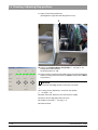
2.3.11Camera quick test
The camera quick test consists of a series of individual test steps, which can
be carried out both in the specified order and individually.
Experienced service
technicians!
Some test steps are made up of several partial steps, some of which can be
activated individually. These functions should only be used by trained technicians.
Operate by clicking the buttons in the bottom right-hand section of the screen.
When carrying out the test steps in the specified order, it is easier to use only
the Next button.
i
NOTE
In many cases "Next" is the same as pressing RETURN.
To select individual test steps, either mark the test step (by clicking it with the
left trackball button, to highlight it in blue) and then select Jump or double
click on the test step.
Test steps can also be selected by choosing Next, previous or repeat.
Select Stop to stop the process. After clicking Stop, the button remains highlighted until the sequence has actually stopped. Stop then returns to its normal shading and the sequence can be continued by selecting the corresponding buttons.
2 - 20
58 35 694 D 3344
D 3344.076.01.05.02 04.2012
2.3 Individual Test Points
Select Exit to exit the test run.
CAUTION
If a blue dialog box appears, you must select Next to continue the sequence
after following the instructions contained in the box.
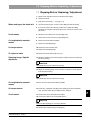
Calibration Set A
If Box A appears, please set Calibration Set A to the 3D camera.
A
Side A
Flat surface
Calibration Set B
If Box B appears, please set Calibration Set B to the 3D camera.
B
Side B
Surface with cross
58 35 694 D 3344
D 3344.076.01.05.02
04.2012
2 - 21
2.3
If you exit the test run without selecting the test step
• "Close Frame Grabber" or
• "Service/Protocol/ Save",
no protocol (log file) is saved.
2.3 Individual Test Points
If a yellow results box appears, select Next to continue the sequence.
The results of the completed test steps are shown in the LOG box during the
sequence.
The entire LOG box can be viewed by scrolling up/down.
Errors can occur while you are carrying out the test steps. Here, it is important
to follow the instructions.
The camera quick test also includes several Service functions, which can be
selected in the Service menu and in the pull-down menus.
i
NOTE
Service functions can only be selected when the test run is stopped.
To end a service function, select a button to continue the test run (e.g. Next).
Service functions consist of:
2 - 22
•
Protocol
•
Live image
58 35 694 D 3344
D 3344.076.01.05.02 04.2012
2.3 Individual Test Points
•
Lifting magnet
•
LED
•
Slide alignment
2.3
Protocol
Select Service/Protocol/Save to create a protocol (log file) during the test
run.
To view the protocol, select Service/Protocol/Display.
Select RETURN to close the protocol (log file) display.
Live image
Moving grid = Search image
Int. LED on (standing grid) = Search image with standing grid - visible grid
stripes
Int. LED off (standing grid) = Search image with internal LED deactivated, so
that objects can only be seen when they are illuminated externally.
Lifting magnet
The lifting magnet is attracted approximately every 3 sec. for a period of
approx. 1 sec. A clicking sound can be heard.
LED and Slide alignment are not required in the camera quick test.
58 35 694 D 3344
D 3344.076.01.05.02
04.2012
2 - 23
2.3 Individual Test Points
The camera quick test Sequence comprises the test steps (functions) listed
below.
Camera calibration data obtained from successfully completed tests are
saved and used in the following camera quick test. These data are not used
for camera operation outside the service program, so that the recording process is not affected by the program.
This also means that the camera must be calibrated before it is used in the
camera quick test. This enables the test steps to produce correct results.
Checking the RGB adjustment is the only test step which can produce correct results without the calibration process being completed.
The test results are indicated in three colors: Green = fully passed, Yellow =
passed, Red = not passed.
CAUTION
Failed tests may be due to a badly prepared calibration set. The uniformity of
the powder coating should then be checked.
It should also be noted that test failures may be the result of a faulty camera
cable or PC drawer (Refer to Chapter 4.14 - 4.16).
In the test step labelled Entry of the header data, a 4-6 figure number must
be entered for the serial number (card).
Carrying out the Closing the frame grabber test step involves generating a
protocol of the completed tests to be stored as a file in the \CEREC\SYSTEM\SERVICE\PROTOCOLS folder. The file name includes the date and
time of the test as well as the camera serial number, if this was entered in the
Entry of the header data test step. If a test step has been carried out several
times, the latest result is entered in the protocol.
2 - 24
58 35 694 D 3344
D 3344.076.01.05.02 04.2012
2.3 Individual Test Points
2.3.12 Info milling unit
2.3
This dialog box contains information on the connected milling unit and the
milling times of the burs.
58 35 694 D 3344
D 3344.076.01.05.02
04.2012
•
Serial number – Serial no. of CC PC board
•
Milling unit ID:
Identifier 0
= CEREC 3 milling unit / scanner (serial number <5000)
Identifier 1
= CEREC inLab milling unit (serial number >5000)
Identifier 2
= CEREC 3 milling unit / scanner (serial number >5000)
Identifier ??
= no milling machine connected
•
Parallel sided burr (min.): – elapsed milling time of parallel-sided bur
•
Cone Shaped (Tapered) burr (min.): – elapsed milling time of tapered
bur
•
Total milling time (min.): – elapsed milling time of milling unit
•
Total scan time (min.): – elapsed scanning time of milling unit
2 - 25
3 Trouble Shooting: Milling Unit
CEREC 3
List of Contents
Trouble Shooting: Milling Unit
List of Contents
3.1
3.2
3.3
3.4
3.5
3.6
3.7
3.8
3.9
3.10
3.11
3-2
Device cannot be switched ON. Green LED (Ready for operation) not illuminated ..........
No connection to PC / acquisition unit. Software cannot be installed..................................
No air pressure ....................................................................................................................
Fan not running. Unit shuts down completely after a short time..........................................
Water pump: Pressure too low ............................................................................................
Defective light barrier...........................................................................................................
Door switch. Please close milling chamber door .................................................................
Motor locking positions: Problems changing grinders .........................................................
Stepping motors (milling unit). Loss of steps.......................................................................
Touch errors ........................................................................................................................
Trouble shooting. Defective CCP board ..............................................................................
3-5
3-7
3-9
3-11
3-13
3-15
3-17
3-19
3-21
3-23
3-25
58 35 694 D 3344
D 3344.076.01.05.02 04.2012
Personal notes
58 35 694 D 3344
D 3344.076.01.05.02 04.2012
3-3
3 -4
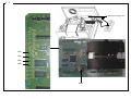
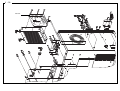
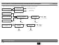
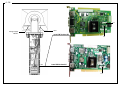
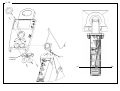
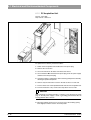
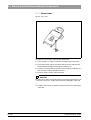
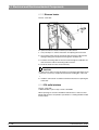
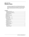
LED on power supply unit
V204
V205
V206
V200
Battery
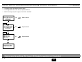
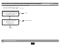
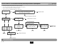
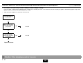
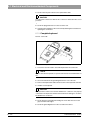
CAUTION: Switch OFF the unit before connecting a measuring instrument or replacing parts!
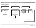
•
Line power supply connected to electric outlet?
•
Line voltage fuses OK? If not: Always replace both fuses.
•
Check line voltage on power supply unit terminal: 100-240V
Green LED on power
supply unit
illuminated?
No
Replace power
No
Replace board
No
Replace board
Yes
CC
CC
Turn ON main switch
Pos. IV204 (42V)
illuminated?
Yes
CC
Lamps
V200 (5V) and
V205 (24V) and
V206 (12V)?
Yes
Board battery
defective/run down
Replacebattery
3.1 Device cannot be switched ON. Green LED (Ready for operation) not illuminated
3-5
3.1
58 35 694 D 3344
D 3344.076.01.05.02 04.2012
3 -6
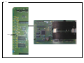
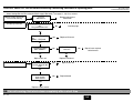
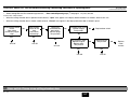
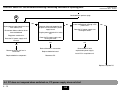
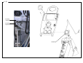
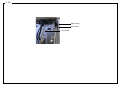
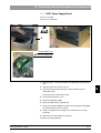
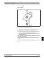
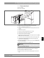
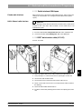
V292
CAUTION: Switch OFF the unit before connecting a measuring instrument or replacing parts!
• CAUTION: Fault may also be on PC/acquisition unit.
•
Check configuration in the Communication menu.
1. Cable version
Connection
OK
Check:
No
•
Serial connecting cable
•
Interface settings on PC / acquisition Unit
Replace board
Replace cable harness
Connection OK?
Yes
Yes
Unit OK
Unit OK
2. Radio controlled version
NOTE: When updating software, it may be necessary
to make several (2-3) attempts at starting.
Connect up using the
cable:
Connection OK?
No
No
Replace board
Connection OK?
Check:
•
Interface settings on PC / acquisition unit
No
Replace cable harness
Yes
Yes
Unit OK
Connect radio module
V 292 (10V)
illuminated?
No
Replace board
Yes
Replace radio module
3.2 No connection to PC / acquisition unit. Software cannot be installed
3-7
3.2
58 35 694 D 3344
D 3344.076.01.05.02 04.2012
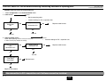
3 -8
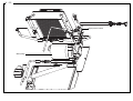
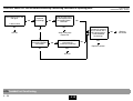
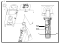
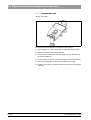
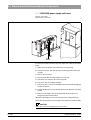
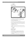
Air pressure switch
Air pump
CAUTION: Switch OFF the unit before connecting a measuring instrument or replacing parts!
•
Select Settings/Service/Test selection/Media supply/Air pump ( see page 2 - 10) Carry out test
Run-up time too short
(0.00)
and
Run-on time too long (0.49)
Check plug
connections on air
pressure switch.
Connect plugs.
Test passed?
Replace air pressure switch
No
Yes
Run-up time too long (4.50)
and
Run-on time too short
(0.00)
Run-on time too long
Current draw too low (0.00)
Replace air pressure switch
Check air hoses
Device OK
Eliminate fault
Check plug
connections on air
pump
Connect plugs.
Test passed?
No
Replace air pump
Yes
Device OK
Current draw too high
(>0.60)
Replace air pump
Test passed?
Yes
Device OK
No
Replace board
Test passed?
No
Replace cable harness
Yes
Device OK
3.3 No air pressure
3-9
3.3
58 35 694 D 3344
D 3344.076.01.05.02 04.2012
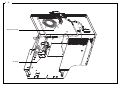
3 - 10
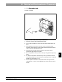
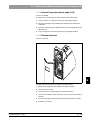
Fan unit
CAUTION: Switch OFF the unit before connecting a measuring instrument or replacing parts!
•
Select Settings/Service/Test selection/Media supply/Fan unit ( see page 2 - 10) Carry out test
Normal current input level,
Fan unit not running
Current input too low
Fan unit
Mechanical
Remove mechanical
obstruction
Check plug connections on fan
unit.
Plug connections OK?
Connect plugs
No
Yes
Are the following LEDs
on?
V320 (L_FAN) and
No
Replace CC board
No
Check line L8.
Line OK?
Yes
Is42VDC applied at
X8.1 and X8.2 ?
Current draw too high
Yes
Yes
Replace fan unit
Replace CC board
Disconnect X8.
Current draw still too
high?
No
No
Repair line or replace
cable harness
Replace fan unit
Yes
Check X8.1 & X8.2 for
short circuits.
Short circuit?
No
Replace board
Yes
Replace cable harness
3.4 Fan not running. Unit shuts down completely after a short time
3 - 11
3.4
58 35 694 D 3344
D 3344.076.01.05.02 04.2012
3 - 12
Water pressure switch
Water pump
CAUTION: Switch OFF the unit before connecting a measuring instrument or replacing parts!
•
Preliminary test: Water tank full. Tank connection button locked in place
•
Select Settings/Service/Test selection/Media supply/Water pump ( see page 2 - 10) Carry out test
time
too short
If theRun-up
test is not
passed,
a "damping box upgrade Check
kit" mustplug
be ordered. Order No.: 58Connect
85 673 plugs.
(0.00)
and
Run-on time too long (0.49)
connections on water
pressure switch
Test passed?
Replace water pressure switch
No
Yes
Run-up time too long (4.50)
and
Run-on time too short
(0.00)
Run-on time too long
and / or
current input too high
Run-up time too long
and
Current input too low
Current input too low (0.00)
Replace water pressure switch
Device OK
Check nozzles on
gearing units and water
water hoses
Remove clogging
Check water hoses
(suction end)
Remove clogging
Check connection:
Tank connector Æ tank
Replace tank connector
Connect plugs.
Test passed?
Check plug
connections on water
pump
Replace water pump
No
Yes
Device OK
Current input too high
Replace water pump
Test passed?
Yes
Device OK
No
Replace board
Test passed?
No
Replace cable
Yes
Device OK
3.5 Water pump: Pressure too low
3 - 13
3.5
58 35 694 D 3344
D 3344.076.01.05.02 04.2012
3 - 14
Light barriers
L_B
L_M
L_G
V503
L_B
V703
L_G
V503
L_M
58 35 694 D 3344
D 3344.076.01.05.02 04.2012
CAUTION: Switch OFF the unit before connecting a measuring instrument or replacing parts!
•
Select Settings/Service/Test selection/Light barriers, …/Light barriers ( see page 2 - 12) Carry out test.
Light barriers defective
V703 (L_G) illuminated?
V503 (L_B) illuminated?
V603 (L_M) illuminated?
Light barriers
contaminated?
Remove contamination
Check plug connections
Connect plugs
No
Replace corresponding
light barrier in G / B/ M axis.
Test passed?
No
Replace board
Test passed?
No
Yes
No
Yes
Unit OK
CAUTION: May be due to
stepping motors Total
failure!
Check all plug
connections
Test passed?
Yes
Unit OK
No
Unit OK
No
Replace board
Test passed?
No
Replace
cable
harness
Yes
Unit OK
3.6 Defective light barrier
3 - 15
3.6
Replace
cable
harness
3 - 16
Slide door switch to upper stop
Door switch
58 35 694 D 3344
D 3344.076.01.05.02 04.2012
CAUTION: Switch OFF the unit before connecting a measuring instrument or replacing parts!
•
Select Settings/Service/Test selection/Light barriers, …/Door switch/Operating keys ( see page 2 - 12) Carry out test
Test the door switch function:
•
When the milling chamber door is opened at both contacts, "Open" must appear in the display before the door has moved a distance of 5 mm.
•
When the milling chamber door is closed at both contacts, "Closed" must appear in the display before the door is locked in place.
Check position of door
switch.
Door switch
positioned at upper
stop?
Yes
No
Slide the door
switch to the
stop.
Door switch
functioning?
No
Check plug
connections on
door switch.
Connect plugs.
Test passed?
Test door switch using
another magnet
Test passed?
Unit OK
Unit OK
Replace door switch
No
Replace board
Test passed?
Yes
Test magnet in door.
Replace magnet.
Replace door.
Test passed?
Yes
Yes
Unit OK
Unit OK
3.7 Door switch. Please close milling chamber door
3 - 17
No
Yes
Yes
Unit OK
No
3.7
No
Replace
cable
harness
3 - 18
Locking pins
CAUTION: Switch OFF the unit before connecting a measuring instrument or replacing parts!
•
Select Settings/Service/Test selection/Light barriers, …/Motor stop positions ( see page 2 - 13) Carry out a test.
•
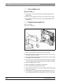
Move grinder to stop position. Replace grinder
Grinder not locked in position (drive
rotates with grinder when attempting to
release the grinder from the drive).
Move grinder to home position.
Locking pins loosened?
No
Check drive.
Can the pressure
spring be pressed in?
No
Replace gearing
see “Replacing the Drive and/or Motor” on
page 7 - 11
Yes
Yes
Reposition and seal locking pins
( see “Checking / Adjusting Stop
positions” on page 7 - 13)
Replace locking pins
(Checking and adjustment of locking
pins
see “Checking / Adjusting Stop
positions” on page 7 - 13)
3.8 Motor locking positions: Problems changing grinders
3 - 19
3.8
58 35 694 D 3344
D 3344.076.01.05.02 04.2012
3 - 20
CAUTION: Switch OFF the unit before connecting a measuring instrument or replacing parts!
•
58 35 694 D 3344
D 3344.076.01.05.02 04.2012
Select Settings/Service/Test selection/Stepping motors ( see page 2 - 14) Carry out test
If step losses occur
in stages 1 to 3
Replace the corresponding stepping
motor
Step losses still indicated?
No
Unit OK
Yes
Replace board
Test passed?
Yes
Unit OK
No
Replace cable
harness
No
Yes
Unit OK
3.9 Stepping motors (milling unit). Loss of steps
3 - 21
3.9
Replace milling machine
3 - 22
CAUTION: Switch OFF the unit before connecting a measuring instrument or replacing parts!
•
Select Settings/Service/Test selection/DC Motors “Touch” ( see page 2 - 16) Carry out test
RMS speed too high,
severe speed fluctuations,
low current (< 0.20)
Current too high (> 0.10)
and motor not turning.
Replace gearing
Check locking
position.
Movement?
No
Replace gearing
Yes
Replace DC motor
Current too low (0.00)
Check plug
connections on
DC motor
Connect plugs.
Test passed?
No
Replace DC motor
Yes
Unit OK
3.10Touch errors
3 - 23
3.10
58 35 694 D 3344
D 3344.076.01.05.02 04.2012
3 - 24
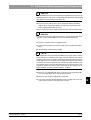
CAUTION: Switch OFF the unit before connecting a measuring instrument or replacing parts!
NOTE: If a CCP board is defective, it must be assumed that this is due to a defective motor rather than a fault on the CCP board.
The motors must therefore be checked first of all.
Do the following:
1. Remove the milling machine PE conductor connector from the bus point.
2. Connect the measuring device between the milling machine PE conductor connector and the PE conductor bus point (DC voltage > 50 V).
NOTE: In all the following tests:
– No fault:
U: < 3 V
– Fault:
U: > 3 V
3. Install a new CCP board.
4. Switch on the unit.
Carry out a stepping motor test
5. Defective motor test (interwinding fault to ground). Adjust voltage to approx. 39V.
DC motor test (run-in / load)
6. If the defective motor (interwinding fault to ground) is tested, a voltage of approx. 22V results.
Other causes
7. If approx. 5V is registered, this indicates a defective light barrier, milling chamber lighting or Hall sensor on one of the DC motors.
8. Locate the cause by disconnecting the individual leads.
9. Switch off the unit. Disconnect from the line power supply.
10. Replace the corresponding part and repeat the test.
11. CAUTION: After repairing the PE conductor - milling machine connection to PE conductor - reconnect the bus point.
3.11Trouble shooting. Defective CCP board
3 - 25
3.11
58 35 694 D 3344
D 3344.076.01.05.02 04.2012
4 Trouble shooting: Acquisition Unit
CEREC 3
List of Contents
Trouble shooting: Acquisition Unit
List of Contents
4.1
4.2
4.3
4.4
4.5
4.6
4.7
4.8
4.9
4.10
4.11
4.12
4.13
4.14
4.15
4.16
4-2
System cannot be switched ON ..........................................................................................
PC not booting properly I.....................................................................................................
PC not booting properly II....................................................................................................
PC does not respond during switch-on, PC power supply does not start............................
Further PC faults .................................................................................................................
Monitor image flickering.......................................................................................................
No monitor display...............................................................................................................
Incorrect monitor display format size...................................................................................
Monitor: Color shade/gray scale is too weak.......................................................................
Trackball not functioning......................................................................................................
Trackball buttons not functioning.........................................................................................
Pedal not functioning ...........................................................................................................
Keyboard not functioning /defective ....................................................................................
No camera image ................................................................................................................
Incorrect measuring sensor setting .....................................................................................
Camera calibration: messages ............................................................................................
4-7
4-9
4-11
4-12
4-14
4-15
4-17
4-19
4-21
4-23
4-25
4-27
4-29
4-31
4-33
4-35
58 35 694 D 3344
D 3344.076.01.05.02 04.2012
4.17
4.18
4.19
4.20
4.21
4.22
Interference at radio interface.............................................................................................
No sound or sound level too low ........................................................................................
No Sirocam camera image .................................................................................................
Sirocam camera image interference...................................................................................
SIROCAM camera: Incorrect image settings......................................................................
Digital X-ray problems ........................................................................................................
58 35 694 D 3344
D 3344.076.01.05.01
04.2012
4-37
4-41
4-43
4-45
4-47
4-49
4-3
Personal notes
58 35 694 D 3344
D 3344.076.01.05.02
04.2012
4-5
4-6
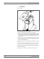
Main switch on rear
of device
LED
L3
Supply line
Keyboard board
X4
DV
DECT supply board
F1/F2
F3
58 35 694D 3344
D 3344.076.01.05.01 04.2012
CAUTION: Switch OFF the unit before connecting a measuring instrument or replacing parts!
•
Line power supply connected to socket?
•
Power plug connected?
•
Power switch on rear of unit switched ON?
•
Power cable attached to PC drawer?
•
Keyboard board cable plug X4 connected to DECT power supply board (DV)?
LED above ON
pushbutton is yellow?
No
Check F1, F2 and F3
fuses. Replace if
necessary.
Is the LED green
when the ON button
Yes
Yes
No
Disconnect the plug on
the keyboard board
lead and check for 5V
on socket X4
(between pins 1 & 6).
5V present?
Yes
Device OK
Is the LED
green
when the ON button
is pressed?
Replace keyboard board TT
No
Replace keyboard board TT
Yes
Unit OK
4.1 System cannot be switched ON
4-7
4.1
No
Check fuse F4
(on DV).
OK?
Yes
Replace DECT power
supply board DV
No
Replace fuse F4
4-8
VGA
CAUTION: Switch OFF the unit before connecting a measuring instrument or replacing parts!
•
Are the keyboard, trackball and VGA cable connected to the monitor on the PC drawer?
•
Is there a disk in the disk drive? If there is, remove it.
•
Is the LED above the ON button yellow or green? – see page 4 - 7
Is the boot-up process interrupted when you try
to access the hard disk during the BIOS startup
or
does a "blue screen" error message appear
when Windows is started?
No
Unit OK
Yes
Boot with restore disk (from PC hardware version
BA) or with bootable image CD-ROM.
No
Replace PC drawer
(CAUTION, loss of data!).
PC booting correctly?
Yes
Unit OK
4.2 PC not booting properly I
4-9
4.2
58 35 694D 3344
D 3344.076.01.05.01 04.2012
4 - 10
Table 1:
List of beep-tone error codes
Table 2:
Error messages during boot-up and possible causes of errors:
Beep tone sequence
Cause of error
Error message
Cause of error
1x short
OK beep following graphics card test.
Floppy disk(s) fail (40):
Voltage supply or data cable to floppy not correctly
plugged in or defective. If the cable is OK, the floppy
disk drive may be defective.
Disk Boot Failure, insert System
Disk and press Enter:
If the primary master disk was not found: Check the
data cable and voltage supply of the hard disk and the
CD/DVD drive.
Press a key to reboot:
Boot sector of hard disk can not be found. Boot with
restore disk (from PC HW version BA) or with bootable
image CD-ROM. If this fails, replace the PC.
If no image is visible yet, check the following points:
Is the monitor switched on and the control LED
illuminated?
If not:
Check the monitor voltage supply.
If the red control LED is illuminated, check the VGA
cable connecting the graphics card to the monitor.
If the green control LED is illuminated (monitor
detects an input signal), check the brightness and
contrast settings of the monitor.
1x long and 3x short
The graphics card is defective or not correctly plugged
in to the motherboard.
Repeatedly long
The memory module on the motherboard is defective
or not correctly plugged in.
58 35 694D 3344
D 3344.076.01.05.01 04.2012
CAUTION: Switch OFF the unit before connecting a measuring instrument or replacing parts!
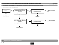
PC power supply starts. PC
begins boot-up procedure.
Boot-up procedure not
correctly completed.
Does the system detect the graphic
card and display it on the monitor?
Are the beep tones audible?
No
Yes
Is a short beep emitted?
No
-->
Yes
No
Next, see page 4 - 13 -->
a
Next,
see page 4 - 13
a
Eliminate errors as outlined in
Table 1,
"List of beep-tone error codes".
Yes
Does the memory test run without
errors?
No
Yes
Does one of the error messages from
the error list appear?
Remove memory module, clean
contact strip
(e.g. rubber eraser).
Plug memory module
in again.
No
Is the PC now functioning
perfectly again?
Is the PC now functioning perfectly?
Yes
Yes
Correct error as specified in Table 2,
"Error messages during boot-up".
Unit OK.
Yes
Unit OK.
4.3 PC not booting properly II
4 - 11
Copying a new image
(CAUTION, loss of data!).
4.3
No
Replace
PC
4 - 12
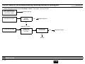
4.4 PC does not respond during switch-on, PC power supply does not start
PC does not respond during switchon, PC power supply does not start.
Is the yellow Standby LED at the top
right of the keyboard illuminated?
No
Yes
Test: Briefly connect pin5 and pin9
to X4 on the DECT power supply
board.
Is a voltage of 230VAC present at the
power input of the PC?
Keyboard, lead L3 or
lead L4 defective.
Replacement of the defective
component.
Check the fuses, connectors and
main switch.
Yes
No
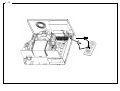
Remove and open the PC drawer.
Check the plug connections of the
boards, the memory banks and the
CPU.
Does the PC boot now?
Yes
No
ATTENTION! Do not press against
the CPU fan. Temporarily connect the
PC power supply and leads L1, L2
and L3.
No
Is the blue
cable between
the motherboard
and the DECT
power supply
board plugged in
at both ends?
No
Connect the
cable. Can the PC
be booted now?
No
Yes
Can the PC now be booted by
pressing the ON key on the
keyboard?
Yes
Yes
Device OK.
Unit OK
Reassemble the PC, slide it into the
acquisition unit and connect the
cables.
Reassemble the PC, slide it into the
acquisition unit and connect the
cables.
Continued on next page
CAUTION: Switch OFF the unit before connecting a measuring instrument or replacing parts!
58 35 694 D 3344
D 3344.076.01.05.02 04.2012
58 35 694D 3344
D 3344.076.01.05.01 04.2012
CAUTION: Switch OFF the unit before connecting a measuring instrument or replacing parts!
Continued from previous page
a
Disconnect power cord from PC.
Unplug power supply from drives and
from auxiliary fan.
Disconnect ribbon cable for drives
from motherboard
No
Disconnect power cable from PC.
Remove all boards except for the
graphic card and the DECT power
supply board.
No
Connect a replacement power supply
to the motherboard and plug in the
power cord.
No
Does the PC power supply start
running this time?
Plug the power cable back in to the
PC.
Plug power cord back in.
Does the PC power supply start?
running?
Does the PC power supply start
running this time?
Yes
Yes
Reinstall boards in succession.
Reassemble PC with
replacement power supply.
Yes
Reconnect drives and fans in
succession.
Replace defective board.
Replace defective component
Reconnect PC.
Install PC in acquisition unit.
Replace complete PC.
4.4 PC does not respond when switched on, PC power supply does not start
4 - 13
4.4
4 - 14
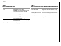
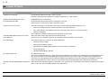
4.5 Further PC faults
Case of defect/fault
How to detect / measure to take
COM port not functioning
Try replacing the radio interface with a cable connection.
If this fails, check whether the COM port is enabled in the BIOS. If it is, replace the PC.
No mouse pointer displayed on screen
Trackball defective or not connected.
No keyboard input possible
Keyboard (keyboard controller) defective or improperly connected.
Check to make sure this fault is not due to bent plug contacts.
Network can not be accessed
LED "10" or LED "100" on the slot plate of the network card must always be illuminated green. If not:
•
The network cable between the network card and the hub / switch is defective.
•
Hub / switch defective (check whether other PCs connected to hub / switch can access the network).
• Network card defective
The "TX Data Act" LED flashes during data communication via the network.
CD-ROM / DVD-ROM missing in list of system
drives (Explorer)
Data cable and/or voltage supply disconnected and/or defective.
If this is not the case, the drive is defective. Test via BIOS: It must be possible to select the drive.
No audio playback
Only a musical CD or only a wave file can not be played back:
No audio playback at all:
•
Check the software settings.
•
Wrong sound card driver installed.
•
Cable between CD-ROM / DVD-ROM drive and sound card loose or defective.
•
Sound card defective.
•
CD-ROM / DVD-ROM drive defective.
No audio playback at all:
Test: Connect loudspeaker directly to sound card without the amplifiers on the DECT power supply board. If an audio playback occurs
then, check the cables to and from the DECT power supply board. Then replace these cables or the DECT power supply board if
necessary. If the sound playback functions without the DECT power supply board: Then the loudspeakers (including the lead) or the
sound card are/is defective, or there is an error in the software setting, or the wrong driver was installed for the sound card.
Warning on monitor indicating that fan RPM is too Check whether the fan brushes against an obstruction. If not, replace the fan. If replacement of the fan does not eliminate fault, replace
low
thePC. In this case, there is probably a defect on the motherboard.
58 35 694 D 3344
D 3344.076.01.05.02 04.2012
58 35 694D 3344
D 3344.076.01.05.01 04.2012
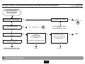
If the image on the monitor flickers, a distinction must be made between two causes:
a) Flickering of the image brightness and
b) Flickering of the image due to incorrectly set monitor parameters
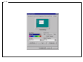
Adjustment of monitor parameters (all types except PV751)
Start Exit
•
Select the mode
in Windows.
•
Press the SELECT/AUTO monitor button twice in succession while in this mode.
The monitor then automatically sets the adjustment parameters.
•
Then exit the "Quit Windows" window with "Cancel".
The monitor is now correctly adjusted.
For type PV751 monitors only (see name plate on rear side of monitor):
•
Set image brightness to maximum value of 130
•
Set contrast to maximum value of 140
If the monitor still flickers following both of these checks, you must then replace
•
the monitor (if monitor type PV751 is not involved) and/or
•
the assembly "power supply, complete" REF 58 09 889, Rep 58 65 550 (see Chapter ‘6.1.5 Complete power supply unit” ).
4.6 Monitor image flickering
4 - 15
4.6
4 - 16
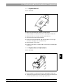
F2
VGA
Voltage supply
Monitor
up to HW Version AB
F4
DV
from HW Version AC
F4
58 35 694D 3344
D 3344.076.01.05.01 04.2012
CAUTION: Switch OFF the unit before connecting a measuring instrument or replacing parts!
•
Are the power supply and the VGA cable connected to the monitor?
•
Is the monitor switched on (LED to the right of the ON switch is red or green)?
•
Is the PC switched on (LED above the ON button is green)?
•
Switch off the monitor and switch it on again after a few moments.
Monitor dark?
Switch off the monitor and disconnect the VGA cable.
Press the "Y" and "S" keys to switch on the monitor.
Does monitor carry out a self-test?
No
No
Replace monitor
Yes
Yes
Device OK. Reconnect VGA cable
Is the LED on the
monitor green or red?
No
Is the monitor switched
ON ?
No
from HW Version AC
Yes
Yes
Switch monitor on. Unit OK.
Yes
to Hardware Version
Is the LED
on the
monitor
green?
Yes
Replace
monitor
Is the LED
on the
monitor
red?
Disconnect the power
supply cable and check
for 12V.
12V present?
Yes
Check VGA cable.
OK?
No
Check and replace F2 fuse on
DP p.c.b. (DECT supply board).
Monitor screen ON?
Yes
Yes
Yes
Replace monitor
Unit OK
Unit OK
No
Replace VGA cable.
Yes
Replace PC drawer
4.7 No monitor display
4 - 17
No
Replace DECT DP
power supply board.
Monitor screen ON?
4.7
No
Replace PC
power supply
4 - 18
CAUTION: Switch OFF the unit before connecting a measuring instrument or replacing parts!
58 35 694D 3344
D 3344.076.01.05.01 04.2012
•
In Windows, select START -> SETTINGS-> CONTROL PANEL> DISPLAY-> SETTINGS to check that the resolution is not set to above 1024X768 (VESA XGA) and that the refresh rate
is set to between 56Hz and 75Hz.
•
When the resolution is set to exactly 1024x768 (VESA XGA), press the SELECT/AUTO button twice to automatically adjust the monitor to the correct setting.
If this does not happen, replace the monitor.
•
When using screen resolutions lower than 1024x768 (VESA XGA): Press the MENU button.
Then press the SELECT/AUTO key once. Select S for Full screen mode.
If this is not possible, replace the monitor.
4.8 Incorrect monitor display format size
4 - 19
4.8
4 - 20
Brightness
Contrast
CAUTION: Switch OFF the unit before connecting a measuring instrument or replacing parts!
58 35 694D 3344
D 3344.076.01.05.01 04.2012
•
Check Windows color pallet setting in the Start -> Settings -> Control -> Display -> settings.
In the color pallet, a setting between 16Bit (High Color = 65536 colors) and 24Bit (True Color = 16777216 colors) must be selected (only applies to 3dfx Voodoo3 graphics card). If other
graphics cards are used, the color pallet setting must be > 16Bit.
•
Adjust the monitor brightness to 140 and the contrast to 130.
Poor color shading/
gray scale?
Yes
Replace VGA cable.
Poor color shading/
gray scale?
No
Unit OK
No
Unit OK
Yes
Replace monitor.
Poor color shading/
gray scale?
Yes
Replace PC drawer.
4.9 Monitor: Color shade/gray scale is too weak
4 - 21
4.9
4 - 22
PS/2 plug
Trackball
PS/2 plug
Keyboard
Trackball
58 35 694D 3344
D 3344.076.01.05.01 04.2012
CAUTION: Switch OFF the unit before connecting a measuring instrument or replacing parts!
Switch device OFF and
ON again.
No
Keyboard
functioning?
Have the PS/2 plugs
for the keyboard and
the trackball been
switched?
No
No
Is the trackball
Attach replacement
trackball or mouse to
the PC drawer with a
PS/2 plug and test.
Trackball/Mouse
functioning?
Yes
Yes
Yes
Unit OK
Swap PS/2 plugs.
Device OK.
Is the PS/2 plug for
the trackball properly
connected?
No
Connect trackball PS/2
plug correctly.
Trackball functioning?
Yes
No
Replace trackball
Yes
Yes
Unit OK
4.10Trackball not functioning
4 - 23
4.10
No
Replace
PC drawer
4 - 24
Keyboard
board TT
L7
L3
DP
58 35 694D 3344
D 3344.076.01.05.01 04.2012
CAUTION: Switch OFF the unit before connecting a measuring instrument or replacing parts!
•
Check whether trackball is functioning
•
Disconnect the pedal and reboot the PC.
•
Check continuity of keyboard board lead L3 (between DECT supply board DP and keyboard board TT).
•
Check trackball power supply.
Check for short circuits of the two pedal
sockets and the pedal
Check continuity on L7 keyboard cable
between trackball and keyboard board.
No
No
Short circuit occurred?
OK?
Yes
Yes
Replace keyboard board TT
Replace pedal or lead L3 between DECT
supply board DP and keyboard board TT .
Trackball buttons functioning?
No
Replace keyboard board TT
Yes
Unit OK
4.11Trackball buttons not functioning
4 - 25
4.11
Repair lead L7 or
Replace trackball
4 - 26
Right-handed
Left-handed
Pedal lead L8
CAUTION: Switch OFF the unit before connecting a measuring instrument or replacing parts!
•
Refer to "Changing from Right-Handed to Left-Handed Operation" in the Operating Instructions for the Acquisition Unit.
Software changeover via Start -> Settings -> Control -> Mouse.
•
Is the plug of pedal lead L8 connected properly?
•
Is the pedal not mechanically obstructed?
Pull off the plug L8.
Both trackball buttons
functioning?
No
Both trackball buttons
functioning?
No
Replace keyboard board (TT)
Yes
Yes
Repair/replace pedal lead
(Microswitch, compl.)
Repair/replace pedal lead
(Microswitch, compl.)
4.12Pedal not functioning
4 - 27
4.12
58 35 694D 3344
D 3344.076.01.05.01 04.2012
4 - 28
Keyboard
PS/2 plug
Trackball
PS/2 plug
Keyboard
L3
DECT
58 35 694D 3344
D 3344.076.01.05.01 04.2012
CAUTION: Switch OFF the unit before connecting a measuring instrument or replacing parts!
•
Check whether the trackball and keyboard PS/2 plugs are properly connected to the PC drawer and not in the wrong sockets (switched).
•
Check continuity on L3 cable to the keyboard board.
LED above ON button
green?
Yes
Replace keyboard
No
Check the supply voltages at the
output socket of the DECT power
supply board (X4.1: +5V and
X4.2:+12V).
No
Replace DECT power supply board
No
Replace keyboard
No
Replace keyboard
Keyboard functioning?
Supply voltage OK?
Yes
Yes
Device OK
Check the supply voltages at the
PS/2 output socket
(PIN 4: +5V and PIN 3: GND) on the
PC drawer.
Replace PC drawer.
No
Keyboard functioning?
Supply voltage OK?
Yes
Yes
Unit OK
Replace keyboard
4.13Keyboard not functioning /defective
4 - 29
4.13
4 - 30
CAUTION: Switch OFF the unit before connecting a measuring instrument or replacing parts!
58 35 694D 3344
D 3344.076.01.05.01 04.2012
1. Is the camera cable properly connected to the camera and the image acquisition (Frame Grabber) card in the PC drawer?
2. For versions up to IDS 2001 only:
Recorded image displayed without camera live image?
If YES, check Windows color pallet setting via Start -> Settings -> Control -> Display -> Settings. In the color pallet, a setting between 16Bit (High Color = 65536 colors) and 24Bit (True
Color = 16777216 colors) must be selected. Change the setting if necessary. It is permissible to select 32Bit on Pentium® III systems.
3. Only for versions up to IDS 2001:
If there is still no live image, check whether the screensaver was activated.
If the answer is YES, select Settings -> Control -> Display -> Screensaver (None). Then accept this setting and reboot the PC if necessary.
4. Carry out camera quick test ( see page 2 - 20).
5. Connect replacement camera cable.
If this fails, connect a replacement camera.
If this also fails, install new software.
If there is still no camera image, the image acquisition (Frame Grabber) card in the PC drawer is probably defective. Replace the Frame Grabber card.
6. CEREC fault message appears when the camera should be activated? YES: install new software.
If no camera image appears, replace the Frame Grabber card.
4.14No camera image
4 - 31
4.14
4 - 32
CAUTION: Switch OFF the unit before connecting a measuring instrument or replacing parts!
•
Check whether the lifting magnet in the 3D camera is briefly activated during the measuring phase. A clicking sound should be heard.
Lifting magnet activated?
Yes
Recalibrate 3D camera
(Refer to the acquisition unit
operating instructions)
•
58 35 694D 3344
D 3344.076.01.05.01 04.2012
No
Connect replacement
camera cable.
Lifting magnet
activated?
No
Connect the
replacement camera to
test it.
Lifting magnet
activated?
Yes
Replace camera cable and
recalibrate 3D camera
No
Replace Grabcer* image acqn. card
*Frame Grabber card
Yes
Replace and
recalibrate 3D camera
Badly adjusted optical impressions may be due to shaking of the camera. The stored optical impression may, however, be OK despite shaking of the camera.
4.15Incorrect measuring sensor setting
4 - 33
4.15
4 - 34
CAUTION: Switch OFF the unit before connecting a measuring instrument or replacing parts!
58 35 694D 3344
D 3344.076.01.05.01 04.2012
There are two types of error messages which can occur during camera calibration:
–
Type 1 are warnings which should be treated seriously. It is possible to temporarily accept these errors by selecting OK and then continue with the calibration process.
–
Type 2 are errors which force the calibration process to stop without the calibration data being saved.
The texts of the error messages give instructions on what to do. Observe the following:
•
Prepare the calibration set properly.
•
Slide the calibration set up to the stop.
•
Ensure that the camera is kept clean (see acquisition unit operating instructions and 3D camera calibration instructions).
If "Image too small.. " is displayed, try to reposition the prism tube in relation to the camera in order to avoid any possible image loss.
If it is not possible to prevent errors from occurring by carrying out the suggested measures, the 3D camera, camera cable or PC drawer may be defective.
First, test the replacement 3D camera. If this does not help, test a replacement camera cable. If this still does not help, test a replacement PC drawer.
The Service program can also be used for diagnosis and documentation purposes.
Select Settings / Service / Camera quick test to test the camera and to record the results in a protocol ( see page 2 - 20 and ff.).
4.16Camera calibration: messages
4 - 35
4.16
4 - 36
Milling Unit
Radio module
CAUTION: Switch OFF the unit before connecting a measuring instrument or replacing parts!
58 35 694D 3344
D 3344.076.01.05.01 04.2012
•
First check the power supplies and cable connections.
•
If no LEDs are illuminated, this indicates that there is a problem with the power supply.
•
Replace the connection cable to determine whether this is the cause of the problem.
•
The serial cable connection on the DECT radio interface basically consists of two null modem cables (There is a 1:1 connection between the pins at either end. Check continuity).
•
The serial cable connection on the Futaba radio interface comprises:
–
A null modem cable with two sockets linking the PC to the radio interface.
–
A serial terminal cable linking the radio interface and milling unit (pins 2 & 3, 4 & 6, 7 & 8 at one end are each reverse-linked to the pins at the other end. Check continuity).
It is important to observe the following in serial links:
•
The baud rate setting in the Cerec program must always be matched to the transmission channel connected. Always select 19200 baud for the Futaba radio interface. For the DECT radio
interface, the configured value (usually 115200 baud) must be selected. Baud rates between 19200 and 115200 can be used for the cable connection between the PC and the milling unit.
115200 baud is normally used. For longer cables (>10m) or when using additional plug connections along the cable route, it may be necessary to reduce the baud rate.
•
The milling unit checks the baud rate at which the software was installed. Should the baud rate be changed, the milling unit must be reinstalled.
•
When the Cerec program is started, it only checks whether a suitable milling unit has been connected to the selected PC serial socket. If a downloaded milling unit is detected, it is then
transferred. If this serial socket is being used by a different application (e.g. Sidexis/Videxis or a program which has already started and is running with the milling unit), the milling unit is
of course not available.
•
If the milling unit is accessed manually from the Cerec program (e. g. when calibrating the scanner, scanning, calibrating the milling unit, milling, changing instruments, carrying out
maintenance or servicing) the milling unit software version is checked automatically. If this serial socket is being used by a different application (e.g. Sidexis/Videxis or a program which has
already started and is running with the milling unit), the milling unit is of course not available.
•
The milling unit status display is only checked at the start of the program and when accessing the milling unit manually. If the milling unit is released by another application (e.g. after
completion of milling), the milling unit can be accessed manually again and the status display is updated in the current program. Only individual status displays are changed. Status displays
in other applications in current use are not changed!
4.17Interference at radio interface
4 - 37
4.17
4 - 38
Left LED
LED
CO/SD/RD
CAUTION: Switch OFF the unit before connecting a measuring instrument or replacing parts!
58 35 694D 3344
D 3344.076.01.05.01 04.2012
4.17.1 DECT radio interface (EU)
The following problems can occur:
•
Radio interfaces are not properly paired or configured. If they are incorrectly paired, the radio interfaces cannot be linked (Left LED flashes and fails to remain illuminated).
•
If several radio interfaces are in use, this increases the load on the DECT frequency band. Due to the component tolerances, the available DECT band frequency range can only
accommodate approx. 8 CEREC3 devices. This can be seen when it takes longer (up to 2 minutes) for the pairs of DECT radio signals to link up. It is not possible to connect the PC to the
milling unit until the DECT pairs are linked (left LED remains illuminated),
•
When using several pairs of radio interfaces, do not position them close together. Place them 1m apart where possible. Interference occurs if the radio modules are too close.
•
If the original Siemens program is used to check the GIGASET M101 data setting, the radio interfaces may block the PC/Milling unit link after exiting the program. This is a common fault
in Siemens software used in radio interfaces. To remedy this problem, interrupt the power supply to both radio modules for few seconds. Then switch on the power again and wait until the
DECT radio pairs link up.
•
Should communication errors occur (Error messages: "Communication interference" or "Milling unit not ready"), this problem can also be remedied by interrupting the power supply to both
radio modules for few seconds. Then switch on the power again and wait until the DECT radio pairs link up.
4.17.2 Futaba radio interface (USA/Japan)
The following problems can occur:
•
Radio interfaces are not correctly adjusted or are defective. Here, no link is made between the two radio interfaces and the LED CO (left) fails to change from red to green.
•
Cable is not properly connected. Here, the CEREC program cannot link up and the data remain in the radio interface buffer for approx. 1 minute. Following an attempted link-up at one of
the radio interfaces, this is indicated when the SD or RD LED is illuminated for approx. 1 minute and does not extinguish immediately afterwards.
4.17Interference at radio interface
4 - 39
4.17
4 - 40
Sound card
L5
CAUTION: Switch OFF the unit before connecting a measuring instrument or replacing parts!
•
Check whether the jack connector on the loudspeaker lead is connected to the green socket for the sound card on the PC drawer.
•
Check the volume level in Windows.
•
Check the L3 lead to the keyboard board.
•
Check the L5 lead connecting the keyboard board to the loudspeakers.
•
Check whether the loudspeakers are installed in the specified positions.
•
Replace the loudspeakers if necessary.
4.18No sound or sound level too low
4 - 41
4.18
58 35 694D 3344
D 3344.076.01.05.01 04.2012
4 - 42
F4
CAUTION: Switch OFF the unit before connecting a measuring instrument or replacing parts!
58 35 694D 3344
D 3344.076.01.05.01 04.2012
Is the fan inside the Sirocam drawer unit running? If not, check the F4 fuse (T2AH) in the base of the device. Check the Sirocam connection lead. Check the F1 (5AT) and F2 (1AT) fuses on
the Sirocam power supply unit plug-in board (Part No. 5854992) in the Sirocam drawer.
Open the SIDEXIS/VIDEXIS application.
Does an error message appear when trying to open the image acquisition window for the live image display as described in the user manual (SIDEXIS/VIDEXIS)? If this happens, check
whether there is another PC application running which operates using the Sirocam or CEREC 3D camera. Close this application and retest the Sirocam camera. If another error message
appears when trying to open the acquisition window for the live image display, then the Frame Grabber card must be replaced.
Check whether the Sirocam camera is properly connected to the Sirocam drawer.
Does the halogen lamp light up when the Sirocam camera is removed from its bracket? If not, replace the halogen lamp (refer to the operating instructions for the acquisition unit).
If the acquisition window for the live image display in the Videxis/Sidexis application is open when the Sirocam camera is removed from its position and the halogen lamp is illuminated, and
there is still no image is displayed, then you must check the lead from the Sirocam module to the PC image acquisition card together with the lead to the camera socket throughout the Sirocam
module. If these cable connections are in fault-free condition, then one of the two plug-in printed circuit boards on the Sirocam module (camera board or SIROCAM power supply unit board)
is defective. First replace the camera board. If the error persists, replace the SIROCAM power supply unit board.
4.19No Sirocam camera image
4 - 43
4.19
4 - 44
Power supply
Camera board
Ferrite core
Camera socket,
compl.
CAUTION: Switch OFF the unit before connecting a measuring instrument or replacing parts!
58 35 694D 3344
D 3344.076.01.05.01 04.2012
If interference occurs during live image displays when using the Sirocam camera, the following steps should be taken in the suggested order:
1. The Sirocam module could be incorrectly connected. Remove the Sirocam module once and then reconnect it. Recheck the camera image.
2. Does the screen interference increase/decrease by shaking the camera cable (at camera end or plug end)? If so, replace the Sirocam camera together with the camera socket lead (Part No.
5811232).
3. Check the continuity in the lead connecting the Sirocam module to the image acquisition (Frame Grabber) card in the PC (compare with circuit diagram specifications). If the interference
increases/decreases by shaking the cable, replace the Sirocam lead (Part No. 5832865).
4. If the screen interference forms horizontal lines, this is probably due to a fault on the image acquisition card in the PC drawer. Replace the image acquisition (Frame Grabber) card.
5. Diagonal lines running across the screen, as opposed to localized interference, are probably due to a fault in the camera electronics on the camera board (Part No. 5864629) or in the camera
socket* leads (Part No. 5811232) and the Sirocam lead (Part No. 5832865). These components must be replaced one after another until the fault has been remedied.
* Check whether the ferrite core is fitted.
4.20Sirocam camera image interference
4 - 45
4.20
4 - 46
Power supply
Camera board
Ferrite core
Camera socket,
compl.
CAUTION: Switch OFF the unit before connecting a measuring instrument or replacing parts!
58 35 694D 3344
D 3344.076.01.05.01 04.2012
•
If only a black/white image appears, it is necessary to check the color intensity and tone settings in SIDEXIS/VIDEXIS. The tone should be set to 0 and the color intensity to approx. 80. If
these settings are correct, the fault is probably caused by a defective Sirocam lead (Part No. 5832865). If a replacement lead fails to remedy the fault, the Frame Grabber card must be
replaced.
•
If the image is too weak, too dark or the colors are too faint, it is necessary to check and possibly change the brightness, contrast, intensity and tone settings in SIDEXIS/VIDEXIS. If changes
are made, make sure you exit the Settings window by selecting OK so that the new values are permanently saved. The recommended default control settings are: BRIGHTNESS=110,
CONTRAST=70, TONE=0, COLOR INTENSITY=80.
•
If the image is still poor, the SIROCAM camera and/or camera board must be replaced.
4.21SIROCAM camera: Incorrect image settings
4 - 47
4.21
4 - 48
CAUTION: Switch OFF the unit before connecting a measuring instrument or replacing parts!
58 35 694D 3344
D 3344.076.01.05.01 04.2012
Should you encounter problems with the digital X-ray box in the acquisition unit, the following procedure is recommended:
1. Is the PC switched on and can an image be seen on the monitor?
2. Check the supply voltage to the X-ray box. Is the X-Ray lead (Part No. 5832832) properly attached? Can approx 5.2 V be measured at the 9-pin D-SUB plug between Pins 7 (+5.2V) and 8
(GND)?
3. Is the X-ray box connected to the practice network and directly linked to the PC ethernet card in the acquisition unit?
If points 1-3 can be confirmed, the faults must be localized with the aid of the SIDEXIS Intraoral service handbook.
4.22Digital X-ray problems
4 - 49
4.22
5 Settings
CEREC 3
List of Contents
Settings
List of Contents
5.1
5.2
5.3
5.4
5.5
5-2
Monitor Settings...................................................................................................................
Calibrating the 3D camera...................................................................................................
Pairing the DECT-radio interface (EU) ................................................................................
Replacing a module of the DECT radio interface (EU)........................................................
Pairing the Futaba radio interface (USA/Japan)..................................................................
5-3
5-4
5-5
5-8
5-9
58 35 694 D 3344
D 3344.076.01.05.02 04.2012
5.1 Monitor Settings
5.1 Monitor Settings
Factory Settings
The monitor is supplied with the following factory settings:
•
Brightness: 140
•
Contrast: 130
•
Press SELECT/AUTO twice to adjust the image position.
Setting the brightness and
contrast
The brightness and contrast can be set to match individual working
environments. The brightness can be adjusted without pressing the MENU
button by using the Yand Sbuttons. To adjust the contrast, first press the
MENU button. Provided that the on-screen display can be seen, it is possible
to press the Yand Sbuttons to adjust the contrast. When the on-screen
display disappears, the setting entered last is stored automatically.
Setting the image and phase
position
It may occasionally be necessary to readjust the image position and the
phase position of the pixels on the monitor. In this case, proceed as follows:
1. First, boot your PC. Next, press the SELECT/AUTO monitor button twice to
allow the monitor to self adjust.
If you are not satisfied with the monitor settings, more precise adjustments
can be made by carrying out the instructions below.
2. Start the NTEST.EXE program
(C:\Programs\NTEST\NTEST.EXE).
3. Position the mouse pointer on the RESOLUTION icon.
Press the left trackball button once and press the right trackball button
once.
4. Press the Menu button on the monitor twice (main menu, page 2) and then
press SELECT/AUTO twice ("FREQUENCY").
Use the Yand S buttons to adjust the monitor until there is no vertical
interference visible in the display.
There is still fine horizontal interference running across the display. To
minimize this interference, press the SELECT/AUTO button again and
select "TRACKING". Use the Yand Sbuttons to optimize the horizontal
settings on the monitor.
5. Press the right trackball button to return to the NTEST main screen.
Press the Menu button on the monitor several times until "Main Menu
Page 2" is displayed.
Press SELECT/AUTO, select "HORIZONTAL POSITION" and
"VERTICAL POSITION" and adjust the position of the display using the Y
and Sbuttons. It is important that each of the outer edges can be seen.
The monitor settings are automatically saved when the on-screen display
disappears.
58 35 694 D 3344
D 3344.076.01.05.02
04.2012
5-3
5.1
Fine black vertical lines over a white background appear on the screen.
5.2 Calibrating the 3D camera
5.2 Calibrating the 3D camera
Refer to the Section with the same title in the acquisition unit instructions.
5-4
58 35 694 D 3344
D 3344.076.01.05.02 04.2012
5.3 Pairing the DECT-radio interface (EU)
5.3 Pairing the DECT-radio interface (EU)
BASE
A
MOBILE PART
The DECT radio interface is paired using the original Siemens program on the
CD supplied with every DECT pair. A standard handbook containing clearly
presented explanations of all the procedures is also supplied with every
DECT pair.
Quick reference guide:
1. Install the original Siemens program from the original CD or from the
directory C:\sirona\gigaset.
However, make sure that you select the latest program version displayed
in the "Gigaset M100 Data SETUP" window following each system start.
58 35 694 D 3344
D 3344.076.01.05.02
04.2012
5-5
5.3
A
5.3 Pairing the DECT-radio interface (EU)
The old program which appears in the "Gigaset M101 Data SETUP"
window should no longer be used, since it fails to recognize modules
equipped with new firmware.
2. If you are not sure whether both DECT radio interfaces are adjusted to the
default settings, reset to the default settings.
For this, take each of the radio interfaces, hold down the black button A
and plug the power supply unit into the electric outlet. Hold the button
down for 30 seconds.! No LEDs should be illuminated during the first 10
seconds. The right LED should then come on.
The radio interface is set to the default settings after the right LED has
extinguished.
3. Disconnect both radio interfaces from the power supply for a few seconds.
Reconnect the two radio interfaces to the power supply.
4. Now attach one radio interface to the COM1 socket on the PC. Place the
other radio interface beside it, without connecting it in series.
CAUTION
The radio interface connected to the PC will be used as the MOBILE UNIT and
integrated in the PC later on.
The other radio interface will be used as the BASE. It will be attached to the
milling unit later on.
5. Start the Siemens program
6. Click on Install and then Local Station.
7. Hold down the black A button on the BASE for more than 10s.
The flashing LED on the left should flash for 10 seconds, and then both
LEDs should begin to flash alternately.
5-6
58 35 694 D 3344
D 3344.076.01.05.02 04.2012
5.3 Pairing the DECT-radio interface (EU)
8. Click Register.
Confirm the following window with OK.
9. After a few seconds, the MOBILE UNIT detects the BASE and this is
indicated in the program. Click Remote adapter to view the BASE which
has been logged on.
10. Click Operating mode
– Operating mode
"Direct connection",
– Bits per second
"115200",
– Data bits
"8",
– Parity
"None (N)",
– Stop bits
"1" and
– Data flow control
"Hardware (RTS/CTS)".
5.3
11. Select the following settings:
12. Click Apply.
The two radio interfaces are now configured using the specified baud rate
and flow control.
13. Click OK to exit the program.
14. Disconnect both radio interfaces from the power supply for a few seconds.
Restart. The radio interfaces are now ready for operation.
58 35 694 D 3344
D 3344.076.01.05.02
04.2012
5-7
5.4 Replacing a module of the DECT radio interface (EU)
5.4 Replacing a module of the DECT radio
interface (EU)
If one of the two radio interfaces must be replaced by a new module, first
make sure that both modules have been programmed with the same
firmware.
To do this, proceed as follows for both modules one after the other:
1. Connect module to COM1 port of PC.
.
2. Insert the CD-ROM supplied with the spare part in the CD-ROM drive.
After starting the Siemens program, press the "Firmware Update" button
3. Confirm the Identification window with Next.
The current version of the firmware in the module is then displayed.
4. If the current version and the latest version on the CD-ROM are identical,
you can terminate the program.
5. If the current version and the latest version on the CD-ROM are not
identical, press the Next button.
The module will then be programmed with the latest firmware (this takes
about 5 minutes).
5-8
58 35 694 D 3344
D 3344.076.01.05.02 04.2012
5.5 Pairing the Futaba radio interface (USA/Japan)
5.5 Pairing the Futaba radio interface (USA/
Japan)
1, 2, 6, ON
2.
1.
3, 4, 5, 7, 8, OFF
D
3.
1.
C
5.5
A
CAUTION
Do not use the Futaba radio interface without the aerial! It must always be
connected to aerial connection A.
In order to provide a communication link between the two radio interfaces, it
is necessary to check/adjust the following:
1. Loosen cover C using a small screwdriver and slide it open.
2. On the DIL switch panel, switches 1, 2 and 6 must be pointing upwards
(ON) and the others must be pointing downwards (OFF).
All radio interfaces are supplied with the same transmission frequency
setting. If several radio interfaces are used in overlapping ranges, they must
be adjusted to different transmission frequencies.
3. On each of the two pairs of linked radio interfaces, the rotary coding switch
D must be set to between 0 and 7.
CAUTION
Switch positions 8 to15 (F) must not be used.
58 35 694 D 3344
D 3344.076.01.05.02
04.2012
5-9
5.5 Pairing the Futaba radio interface (USA/Japan)
Different switch settings must be used on all pairs of radio interfaces in
operation in the same area. This limits the number of radio links which can be
used in one area to a maximum of 8 pairs.
If the settings are changed, interrupt the power supply for a few seconds to
make sure that the new switch positions are registered in the internal logic
elements.
The Futaba radio interface is now automatically set to a baud rate of 19200
and the hardware flow control is configured.
5 - 10
58 35 694 D 3344
D 3344.076.01.05.02 04.2012
6 Acquisition Unit: Repairs
CEREC 3
List of Contents
Acquisition Unit: Repairs
List of Contents
6.1
6.2
6-2
Electrical and Electromechanical Components ................................................................... 6-4
Mechanical components...................................................................................................... 6-30
58 35 694 D 3344
D 3344.076.01.05.02 04.2012
Personal notes
58 35 694 D 3344
D 3344.076.01.05.02
04.2012
6-3
6.1 Electrical and Electromechanical Components
6.1 Electrical and Electromechanical
Components
i
NOTE
When replacing electrical and electromechanical components, please refer to
the wiring diagrams of the exposure unit to determine the correct designations
for fuses, leads and PC boards.
6.1.1 Fuses
Fuses generally may be replaced only with fuses of the same type and size.
The following fuses can be replaced by a service engineer on site:
Line power supply input filter
fuses F1 and F2
Replacement of the F1 (T5AH/from Series No. 3300: T6.3AH) and F2 (T5AH/
from Series No. 3300: T6.3AH)fuses in the line power supply input filter is
explained in the Section "Main fuses" in the acquisition unit instructions.
Secondary circuit fuse,
isolating transformer F3
In order to change fuse F3 (T1.25AL), you must first place the acquisition unit
on its side. The fuse holder for F3 is mounted on the bottom side of the unit
base.
F4
T2AH
F3
T1.25AL
Sirocam heater fuse F4
6-4
In order to change fuse F4 (T2AH), you must first place the acquisition unit on
its side. The fuse holder for F4 is mounted on the bottom side of the base
plate.
58 35 694 D 3344
D 3344.076.01.05.02 04.2012
6.1 Electrical and Electromechanical Components
Fuses on the video power
supply unit board
A
XS1
XS3
A
The Sirocam module must be pulled out of the acquisition unit in order to
change the fuse on the power supply unit PC board. Proceed as follows:
1. Disconnect connectors XS1 and XS3 from the camera board.
2. Remove the four screws A from the shield plate.
3. Fold out the shield plate from the side. The power supply board can now be
seen.
4. Now replace fuses F1 (T5AH) and F2 (T1AL) on the video power supply
unit board.
5. Reinstall and screw on the shield using the 4 screws (A).
6. Plug connectors XS1 and XS3 back in.
Make absolutely sure that two-pin connector XS3 is plugged in to the left edge
of the video board as shown.
7. Slide the Sirocam module into the acquisition unit and connect the
Sirocam camera.
58 35 694 D 3344
D 3344.076.01.05.02
04.2012
6-5
6.1
CAUTION
6.1 Electrical and Electromechanical Components
6.1.2 PC Acquisition Unit
Part No.: 58 73 042
Rep. Part No.: 58 65 519
B
To replace the PC drawer, proceed as follows:
1. Switch off the acquisition unit and disconnect the power plug.
2. Remove the rear section.
3. Unscrew and remove all cables from the back of the PC.
4. Unscrew bracket B located above the power plug on the PC power supply
and disconnect the power plug.
5. Open the front door, pull apart the Velcro fastening and open the door fully,
allowing the pedal to drop down.
6. Remove only the two bottom screws in the side sections on each side.
7. The PC drawer can now be pulled forwards and out of the acquisition unit.
8. To fit the PC drawer, carry out the same steps but in reverse order.
CAUTION
Make absolutely sure that bracket B is screwed on correctly above the power
plug on the PC power supply. It forms a grounding point between the PC
housing and the device chassis.
9. Move the pedal up and secure. If necessary, press the retaining spring
back slightly to make it easier to insert the pedal.
6-6
58 35 694 D 3344
D 3344.076.01.05.02 04.2012
6.1 Electrical and Electromechanical Components
6.1.3 DECT Power Supply Board
Part No.: 58 73 083
Rep. Part No.: 58 65 584
A
Frame Grabber card
DECT power supply board
1. Perform points 1 to 7 in the instructions for replacing the PC Acquisition
Unit.
6.1
2. Undo the strap on the bottom of the PC.
3. Unlock housing catch A und pull front section with drive forward
(CAUTION: leads).
Lift off foam plastic shell and lay it aside.
4. Unscrew and remove the screw.
5. Disconnect plugs X1 and X2.
6. Remove the DECT power supply board.
7. Plug connectors X1 and X2 into the DECT power supply board supplied
Insert the board and screw it on firmly.
8. Position foam plastic shell, making sure that the drives are correctly
positioned.
9. Slide on the front part until it locks into place.
10. Attach the strap and tighten.
58 35 694 D 3344
D 3344.076.01.05.02
04.2012
6-7
6.1 Electrical and Electromechanical Components
6.1.4 Frame Grabber card
Part No.: 58 73 091
Rep. Part No.: 58 65 592
1. Perform points 1 to 4 of the instructions for replacing the DECT Power
Supply Board.
2. Remove the frame grabber card, insert a new card and screw on firmly.
3. Perform points 8 to 10 of the instructions for replacing the DECT Power
Supply Board.
6.1.5 Complete power supply unit
Part No.: 58 09 889
Rep. Part No.: 58 65 550
SIROCAM
To replace the power supply unit, proceed as follows:
1. Switch off the acquisition unit and disconnect its power plug.
2. Remove the rear section, unscrew and remove the three screws on the
cover plate and remove the plate.
3. Unscrew the bracket located above the power plug on the PC power supply
unit and disconnect the power plug.
4. If necessary, disconnect the plug connection of the monitor power supply
(if a power supply unit with a separate monitor power supply is installed).
5. Place the acquisition unit on its side.
6. Remove all holding screws attached to the base plate.
7. Take out the base plate and place it to one side.
8. Disconnect the power cable to the PC power supply unit and the grounding
cable on the cover plate.
9. If the acquisition unit is equipped with the SIROCAM option, disconnect
lead L12 (SIROCAM lead) at the isolating point to the Sirocam transformer.
6-8
58 35 694 D 3344
D 3344.076.01.05.02 04.2012
6.1 Electrical and Electromechanical Components
CAUTION
The SIROCAM transformer, the fuse holder and the 56W series resistor for the
SIROCAM heater as well as the corresponding leads all must be removed and
reinstalled in the replacement power supply unit.
10. Insert the power cable to the PC power supply unit and the grounding
cable for the cover plate through the rear side of the unit and reconnect
lead L12 (SIROCAM lead) if necessary.
11. Insert replacement power supply unit into the base and screw down firmly.
CAUTION
It is important to make sure that the leads are not crushed and that they do not
come into contact with the 56W series resistor for the Sirocam heater.
12. Place the acquisition unit in an upright position.
13. Connect power plug to the PC power supply and screw down the bracket
firmly.
14. Connect plugs of monitor power supply.
i
NOTE
If the LCD monitor was powered by the DECT power supply board of the PC
drawer before the complete power supply unit was replaced, this will be
changed. In the future the monitor will be powered by the separate monitor
power supply unit of the "complete power supply unit" module. To perform this
conversion, the monitor lead previously used must be replaced with the new
one supplied. The procedure for dismantling the front and rear housing covers
required to replace the monitor lead is described in the chapters ‘6.2.10
Monitor adapter” and ‘6.2.11 Monitor support, complete” .
15. Screw on cover plate tight with three screws. Also screw grounding cable
on to cover plate. Make sure to use the special washer.
17. If necessary, attach a label specifying the new fuse ratings to the rear side
of the unit base. Affix the new label over the old one.
58 35 694 D 3344
D 3344.076.01.05.02
04.2012
6-9
6.1
16. Attach the rear section and plug in the power cord.
6.1 Electrical and Electromechanical Components
6.1.6 Control unit
Part No.: 58 10 853
C
To replace the control unit, proceed as follows:
1. Switch off the acquisition unit and disconnect its power plug.
2. Remove the rear section, detach the VGA lead on the graphics card and
the power supply lead to the monitor at the DECT supply point. Remove
the star knob screws of the monitor mounting and lift the monitor off of the
acquisition unit.
3. Disconnect the cameras from the acquisition unit and keep in a safe place.
4. Unscrew the control unit at the rear end of the handle and at the monitor
support. Unscrew and remove C.
5. Disconnect the keyboard and trackball leads from the PS/2 sockets on the
PC.
6. Unscrew and remove the grounding band from the rear side of the unit.
7. Lift the control unit off the acquisition unit and open the cable fasteners.
8. Disconnect leads L3, L10/L20, L13 and HP1 from the keyboard board.
9. Remove the control unit.
10. To install the new control unit, carry out Steps 1-8 in reverse order.
6 - 10
58 35 694 D 3344
D 3344.076.01.05.02 04.2012
6.1 Electrical and Electromechanical Components
6.1.7 Keyboard board
Part No.: 58 09 954
To replace the keyboard board, follow the procedure below:
1. Carry out Steps 1 to 9 in the instructions for replacing the Control unit.
2. Disconnect leads L4, L5 and L7 from the keyboard board.
3. Unscrew and remove the keyboard board.
4. Position the new keyboard board, align (ensuring there is an even gap
around the side edges) and screw down firmly.
5. Reconnect leads L4, L5 and L7.
6. Install the control unit in accordance with the instructions for replacing the
Control unit.
6.1.8 Keyboard board (L3) lead (L3)
6.1
Part No.: 58 10 044
L3
To replace lead L3 on the keyboard board, follow the instructions below:
1. Carry out Steps 1 to 9 in the instructions for replacing the Control unit.
2. »Remove the plug panel on the rear of the device and unscrew the two jack
sockets in the panel used for connecting the pedal cable.«
58 35 694 D 3344
D 3344.076.01.05.02
04.2012
6 - 11
6.1 Electrical and Electromechanical Components
3. Screw in the two jack sockets for the replacement cable.
CAUTION
It is important to make sure that the two sockets are attached in the correct
positions!
4. Screw the plug panel back on to the rear of the unit.
5. Complete the installation of the control unit by following the instructions for
replacing the control unit.
6.1.9 Complete keyboard
Part No.: 58 10 796
To replace the keyboard board, follow the procedure below:
1. Loosen the four nuts used to attach the keyboard to the control unit.
i
NOTE
If a Sirocam camera is present, a special screw must be loosened instead of a
nut.
2. Unscrew and remove the grounding band on the rear of the unit.
3. Take out the keyboard and disconnect lead L4 on the keyboard controller.
4. Install the new keyboard.
CAUTION
It is important to make sure that the flexible track conductors are properly
connected to the keyboard controller board and that no damage is caused to
the flexible track conductors.
5. Screw down the new keyboard and align to ensure that there is an even
gap around the side edges.
6. Screw the grounding band on to the rear side of the device.
6 - 12
58 35 694 D 3344
D 3344.076.01.05.02 04.2012
6.1 Electrical and Electromechanical Components
6.1.10Trackball
Part No.: 58 33 053
To replace the trackball, follow the procedure below:
1. Unscrew and remove the ring around the ball.
2. Carry out Steps 1 to 9 in the instructions for replacing the Control unit.
3. Disconnect lead L7 from connector X4 of the keyboard board.
4. Undo the screw connection between the trackball and the control unit and
remove the trackball from the upper side of the control unit.
5. Position the new trackball on the underside of the control unit and screw in
place from the upper side.
7. To install the control unit, follow the instructions for replacing the control
unit.
8. Insert the trackball and screw on the outer ring again.
The ease of action of the trackball can be set by selecting the stop position of
the ring.
58 35 694 D 3344
D 3344.076.01.05.02
04.2012
6 - 13
6.1
6. Reconnect lead L7. Route the lead from the trackball to plug PS/2 on the
PC at the rear of the device.
6.1 Electrical and Electromechanical Components
6.1.11 Loudspeaker unit
Part No.: 58 32 808
To replace the entire loudspeaker, follow the procedure below:
1. Carry out Steps 1 to 7 in the instructions for replacing the Control unit.
2. Disconnect lead L5 from the keyboard board.
3. Release the two loudspeakers from the spring locks (e.g. with the aid of
two small screwdrivers).
4. Connect lead L5 on the new pair of loudspeakers to the keyboard board.
5. Insert each loudspeaker into the side hole indicated by its cable.
6. Install the control unit in accordance with the instructions for replacing the
control unit.
6 - 14
58 35 694 D 3344
D 3344.076.01.05.02 04.2012
6.1 Electrical and Electromechanical Components
6.1.12 Microswitch unit
Part No.: 58 10 739
To replace the microswitch, follow the procedure below:
1. Place the unit on its side and fold away the pedal.
2. Use a torque screwdriver to remove the entire microswitch from the unit
base.
3. Before fitting the new switch, loosen the screws on the microswitch
mounting and then push the switch together inside the elongated slots in
order to avoid any damage beforehand.
5. Move the pedal to its release position at the stop using adhesive tape or by
hand.
6. It is important to push the microswitch up as far as possible to allow the
microswitch plunger to be held back by the spring clip, without completely
bending (or over-bending - see 3.).
7. After the pedal is activated or released, the switch must open from its
resting position so that it can be triggered from all sides when the door is
closed.
58 35 694 D 3344
D 3344.076.01.05.02
04.2012
6 - 15
6.1
4. Screw the new microswitch into the unit base and ensure that it is
positioned at right angles to the pedal.
6.1 Electrical and Electromechanical Components
6.1.13 LCD monitor unit
Part No.: 58 10 143
Rep. Part No.: 58 65 535
D
L1
L2
To replace the LCD monitor unit, follow the procedure below:
1. Switch off and unplug the acquisition unit.
2. Take off the back section and disconnect the VGA lead (L1) on the
graphics card and the power supply lead to the monitor (L2) at the DECT
supply point. Remove the three star grip screws D on the monitor mounting
and lift the monitor off the acquisition unit.
3. Install the new monitor from above. Here you must feed the VGA lead and
the power supply cable for the monitor (L2) through the opening on the
monitor support and through to the rear of the unit.
4. Attach the monitor firmly using the 3 start grip screws D, starting with one
screw at the rear. Screw the VGA lead on to the graphics card and connect
the power supply lead for the monitor to the DECT supply.
6.1.14VGA lead
1. For instructions on how to remove the front and rear monitor panels, see
‘6.2.10 Monitor adapter” and ‘6.2.11 Monitor support, complete” .
2. Replace the VGA lead and reinstall the monitor panels.
6 - 16
58 35 694 D 3344
D 3344.076.01.05.02 04.2012
6.1 Electrical and Electromechanical Components
6.1.15 3D camera
Part No.: 58 09 863
Rep. Part No.: 58 65 543
To replace the 3D camera, follow the procedure below:
1. Disconnect the old 3D camera from the camera cable and attach the new
3D camera.
2. Calibrate the 3D camera with the aid of the CEREC application (see 3D
Camera calibration in the acquisition unit operating instructions).
6.1.16Cerec camera lead
Part No.: 5832873
To replace the Cerec camera lead, follow the procedure below:
1. Carry out Steps 1 to 9 in the instructions for replacing the Control unit.
2. Disconnect the Cerec camera lead from the image processing board in the
PC drawer.
3. Remove the right-hand side section. Here you must remove the three side
screws and the rear connecting screw between the side section and the
control unit.
4. Remove the old camera lead and install a new one.
CAUTION
It is important to ensure that the exposed cable between the reinforcing sleeve
affixed to the side and the camera plug is exactly the same length as the
previous camera cable. It may be necessary to reposition the sleeve on the
cable.
5. Connect a new camera lead to the image acquisition card in the PC drawer
and screw in place.
7. Insert the side section from the rear of the unit and attach it to the control
unit using the three side screws and the connecting screw.
CAUTION
It is important to make sure that the side section fits snugly into the rear
guideways!
58 35 694 D 3344
D 3344.076.01.05.02
04.2012
6 - 17
6.1
6. Install the control unit in accordance with the instructions for replacing the
control unit.
6.1 Electrical and Electromechanical Components
6.1.17 Cerec heater
Part No.: 58 11 190
To replace the Cerec heater, follow the procedure below:
1. Carry out Steps 1 to 9 in the instructions for replacing the Control unit.
2. Unscrew the heater from the control unit. Disconnect the cable from the
keyboard board and pull it out through the ventilation slot.
3. Feed the connecting cable for the new heater through the ventilation slot
and connect the cable to the keyboard board.
4. Screw the heater on to the control unit firmly.
CAUTION
It is important to make sure that the heater is positioned at right angles to the
control unit. If necessary, readjust the heater after installing the control unit.
5. Install the control unit in accordance with the instructions for replacing the
control unit.
6 - 18
58 35 694 D 3344
D 3344.076.01.05.02 04.2012
6.1 Electrical and Electromechanical Components
6.1.18 Cerec camera board
Part No.: 58 64 629
Rep. Part No.: 58 65 568
XS1
XS3
To replace the Cerec camera board, follow the procedure below:
1. Switch off and unplug the acquisition unit.
2. Open the front door, pull apart the Velcro fastening and take off the door
carefully.
3. Remove the cover plate.
4. Disconnect the Sirocam plug and place it to one side.
5. Pull out the lock and turn it 90° to the left (CCW).
6. Pull out the Sirocam module completely.
7. Disconnect the two plugs on the lead of the complete camera socket (XS1,
XS3) from the Cerec camera board.
9. Connect the new camera board to the Sirocam power supply cable,
position and screw together firmly.
10. Connect the two plugs on the complete camera socket lead (XS1, XS3) to
the Cerec camera board.
11. Slide the Sirocam module into the acquisition unit.
CAUTION
Make sure that the plug at the end of the rear module is properly inserted into
the socket on the matching component!
12. Turn the lock 90° to the right (CW) and then position the locking bar.
13. Plug in the Sirocam and put on the cover plate.
14. Raise the front door, press the Velcro fastening together and close the
door.
58 35 694 D 3344
D 3344.076.01.05.02
04.2012
6 - 19
6.1
8. Unscrew the camera board and pull off the Sirocam power supply cable.
6.1 Electrical and Electromechanical Components
6.1.19SIROCAM power supply unit board
Part No.: 58 72 549
Rep. Part No.: 58 72 556
XS1
XS3
To replace the board on the Sirocam power supply unit, follow the procedure
below:
1. Switch off the acquisition unit and disconnect its power plug.
2. Open the front door, pull apart the Velcro fastening and take off the door
carefully.
3. Remove the cover plate.
4. Disconnect the Sirocam plug and place it to one side.
5. Pull out the lock and turn it 90° to the left (CCW).
6. Pull out the Sirocam module completely.
7. Remove the four screws on the shield plate for the two boards belonging to
the Sirocam drawer.
8. Pull the shield plate out of the Sirocam drawer in the direction of the lamp
module.
9. Disconnect the cable to the camera board and also the leads to the
halogen lamp, thermostat and fan.
10. Remove the holding screws on the Sirocam power supply unit board.
11. Position the new Sirocam power supply unit board and screw it down firmly.
CAUTION
Attach the screws on the 25-pin plug connector first!
6 - 20
58 35 694 D 3344
D 3344.076.01.05.02 04.2012
6.1 Electrical and Electromechanical Components
12. Connect the leads to the halogen lamp, thermostat, fan and camera board.
13. Position the shield plate with the attached boards and screw it down firmly.
14. Slide the Sirocam module into the acquisition unit.
CAUTION
Make sure that the plug at the end of the rear module is properly inserted into
the socket on the matching component! It may be necessary to unscrew the
matching component from the Sirocam lead and to reconnect it after sliding in
the Sirocam module.
15. Turn the lock 90° to the right (CW) and then position the locking bar.
16. Connect the Sirocam plug and put on the cover plate.
6.1
17. Raise the front door, press the Velcro fastening together and close the
door.
58 35 694 D 3344
D 3344.076.01.05.02
04.2012
6 - 21
6.1 Electrical and Electromechanical Components
6.1.20 Sirocam lead L12
Part No.: 58 32 865
L12
To replace the SIROCAM lead, follow the procedure below:
1. Switch off the acquisition unit and disconnect its power plug.
2. Remove the rear section.
3. Release and remove the Sirocam lead plug on the image acquisition card
of the PC drawer and on the Sirocam drawer.
4. Undo the three screws on the cover plate and remove the plate.
5. Place the acquisition unit on its side.
6. Remove all the base plate holding screws.
7. Take out the base plate and place it to one side.
8. Disconnect the Sirocam lead at the Sirocam transformer isolating point
and pull out the lead from the rear of the device.
9. Feed in the new lead from the rear and connect it to the transformer lead.
10. Position the base plate and screw down firmly.
11. Place the acquisition unit in an upright position.
12. Replace and screw down the cover plate. Then screw the grounding cable
onto the cover plate. Make sure to use the special washer.
13. Connect the Sirocam lead to the image acquisition card in the PC drawer
and screw it down.
14. Connect the Sirocam lead to the rear of the Sirocam module and screw it
down firmly.
6 - 22
58 35 694 D 3344
D 3344.076.01.05.02 04.2012
6.1 Electrical and Electromechanical Components
6.1.21Complete light module unit
Part No.: 58 55 114
A
NSB
To replace the entire light module unit, follow the procedure below:
2. Open the front door, pull apart the Velcro fastening and take off the door
carefully.
3. Remove the cover plate.
4. Disconnect the Sirocam plug and place it to one side.
5. Pull out the lock and turn it 90° to the left (CCW).
6. Pull out the Sirocam module completely.
7. Remove the four fixing screws A on the light module.
8. Disconnect the thermostat, fan and halogen lamp leads from the Sirocam
(NSB) power supply board.
9. Gently withdraw the light module from the camera socket and remove it.
10. Position the new light module and screw it in place.
CAUTION
It is important to make sure that the fiber-optic rod inside the camera socket is
not damaged!
58 35 694 D 3344
D 3344.076.01.05.02
04.2012
6 - 23
6.1
1. Switch off the acquisition unit and disconnect its power plug.
6.1 Electrical and Electromechanical Components
11. Connect the thermostat, fan and halogen lamp leads to the Sirocam (NSB)
power supply board.
12. Slide the Sirocam module into the acquisition unit.
CAUTION
Make sure that the plug at the rear end of the module is properly inserted into
the socket on the matching component!
13. Turn the lock 90° to the right (CW) and then position the locking bar.
14. Connect the Sirocam plug and put on the cover plate.
15. Raise the front door, press the Velcro fastening together and close the
door.
6.1.22Complete camera socket
Part No.: 58 11 232
A
6 - 24
NSB
58 35 694 D 3344
D 3344.076.01.05.02 04.2012
6.1 Electrical and Electromechanical Components
To replace the camera socket, follow the procedure below:
1. Switch off the acquisition unit and disconnect its power plug.
2. Open the front door, pull apart the Velcro fastening and take off the door
carefully.
3. Remove the cover plate.
4. Disconnect the Sirocam plug and place it to one side.
5. Pull out the lock and turn it 90° to the left (CCW).
6. Pull out the Sirocam module completely.
7. Remove the four holding screws from the light module.
8. Disconnect the thermostat, fan and halogen lamp leads from the Sirocam
power supply board.
9. Gently withdraw the light module from the camera socket and remove it.
10. Remove the camera socket fastening screws.
11. Completely disconnect the two plugs on the camera socket lead from the
Cerec camera board.
12. Press the lead grommet out of the partition plate and take it off the lead.
13. Release the ferrite piece from the drawer plate and remove the entire
camera socket lead.
14. Screw in the camera socket attached to the new lead.
15. Position and attach the ferrite piece belonging to the new lead.
16. Place the grommet on the lead and press it into the partition plate.
17. Connect the two plugs on the camera socket lead to the Cerec camera
board.
18. Position the light module and screw it in place.
CAUTION
19. Connect the thermostat, fan and halogen lamp leads to the Sirocam power
supply board.
20. Slide the Sirocam module into the acquisition unit.
CAUTION
Make sure that the plug at the rear end of the module is properly inserted into
the socket on the matching component!
21. Turn the lock 90° to the right (CW) and then position the locking bar.
22. Connect the Sirocam plug and put on the cover plate.
23. Raise the front door, press the Velcro fastening together and close the
door.
58 35 694 D 3344
D 3344.076.01.05.02
04.2012
6 - 25
6.1
It is important to make sure that the fiber-optic rod inside the camera socket is
not damaged!
6.1 Electrical and Electromechanical Components
6.1.23 Sirocam heater
Part No.: 58 32 907
To replace the Sirocam heater, follow the procedure below:
1. Carry out Steps 1 to 9 in the instructions for replacing the Control unit.
2. Unscrew the heater from the control unit. Disconnect the cable from the
floating isolating point and pull it out through the ventilation slot.
3. Feed the connecting cable for the new heater through the ventilation slot
and connect the cable to the floating cable connector.
4. Screw the heater onto the control unit firmly.
CAUTION
It is important to make sure that the heater is positioned at right angles to the
control unit. If necessary, readjust the heater after installing the control unit.
5. Install the control unit in accordance with the instructions for replacing the
control unit.
6.1.24EU radio interface
Part No.: 58 32 998
or DECT module, 1-piece. Rep. Part No.: 58 65 600
When replacing one or both of the DECT radio interfaces, make sure that
linked radio interfaces are paired as specified in ‘5.3 Pairing the DECT-radio
interface (EU)” .
6 - 26
58 35 694 D 3344
D 3344.076.01.05.02 04.2012
6.1 Electrical and Electromechanical Components
6.1.25 Radio interface USA/Japan
Futaba radio interface
When replacing one or both of the Futaba radio interfaces, make sure that the
settings are as specified in ‘5.5 Pairing the Futaba radio interface (USA/
Japan)” .
Höft & Wessel radio interface
CAUTION
When replacing a Höft & Wessel radio interface module, always replace both
modules at the same time. These modules can be mated only at the
manufacturer’s plant.
1. Insert the module labeled Acquisition Unit „FT“ in the acquisition unit.
2. Connect the module labeled Milling Unit „PT“ to the milling unit.
6.1.26DECT data transfer cable (L11/L21)
Part No.: 58 57 367
L21
To replace the DECT data transfer cable, follow the procedure below:
1. Carry out Steps 1 to 9 in the instructions for replacing the Control unit.
2. Unscrew the radio module bracket.
3. Unscrew, disconnect and remove data transfer cable L11/L21.
4. Route, connect and screw on new L11/L21 data transfer cable as shown in
the drawing.
5. Screw the radio module bracket back on.
6. Install the control unit by following the instructions for replacing the control
unit.
58 35 694 D 3344
D 3344.076.01.05.02
04.2012
6 - 27
6.1
L11
6.1 Electrical and Electromechanical Components
6.1.27 XAB IO
Spare Part No.: 51 68 427
Rep. Part No.: 51 68 435
XAB D
XAB IO
C
B
L14
To replace the XAB IO, follow the procedure below:
1. Carry out Steps 1 to 9 in the instructions for replacing the Control unit.
2. Disconnect plug of network lead L14. Unscrew and remove plug B.
3. Unscrew the radio module bracket.
4. Remove screw C and take out the X-ray module.
5. Unscrew the 2 screws on the X-ray module and take off the cover panels.
6. Disconnect all plugs from the XAB IO PC board and unscrew the board.
7. Screw on the new XAB IO PC board and reconnect the plugs previously
disconnected.
8. Screw the cover panels back on.
9. Insert the X-ray module and attach with screw C and the radio module
bracket.
10. Reconnect plug B and screw it on firmly. Connect plug of network lead L14.
6.1.28XAB D
Spare Part No.: 51 68 443
Rep. Part No.: 51 68 450
To replace the XAB D:
1. Carry out Steps 1 to 5 in the instructions for replacing the XAB IO.
2. Disconnect all plugs from the XAB D board and unscrew the board.
3. Screw on the new XAB D board and reconnect the plugs previously
disconnected.
4. Carry out Steps 8 to 10 in the instructions for replacing the XAB IO.
6 - 28
58 35 694 D 3344
D 3344.076.01.05.02 04.2012
6.1 Electrical and Electromechanical Components
6.1.29Internal X-ray data transfer cable (L13)
Part No.: 58 32 840
To replace the X-ray data transfer cable, follow the procedure below:
1. Carry out Steps 1 to 5 in the instructions for replacing the XAB IO.
2. Disconnect all plugs from the XAB IO board and take out data transfer
cable L13.
3. Insert the new data transfer cable L13 and reconnect the plugs previously
disconnected.
4. Carry out Steps 8 to 10 in the instructions for replacing the XAB IO.
6.1.30External interface
6.1
Part No.: 58 57 375
To replace the external interface, follow the procedure below:
1. Switch off the acquisition unit and disconnect its power plug.
2. Remove the rear section.
3. Unscrew and remove all the plugs on the external interface.
4. Unscrew the external interface (3 screws) and screw on the new external
interface.
5. Reconnect the plugs previously disconnected and screw them on firmly.
6. Install the rear section.
58 35 694 D 3344
D 3344.076.01.05.02
04.2012
6 - 29
6.2 Mechanical components
6.2 Mechanical components
CAUTION
Disconnect the line power supply BEFORE replacing any parts.
6.2.1 Front flap
Complete front flap, Part No.: 58 10 762
Front flap, Part No.: 58 10 838
1. Swing the pedal down.
2. Loosen the L/R screws on the door support (screws need not be
unscrewed completely).
3. Turn the front flap together with the door support and remove both.
4. To install, carry out the same steps in reverse order.
5. Door adjustment:
Adjust the gap between the control unit and the door to approx. 1.5 - 2 mm.
Tighten the L/R screws firmly.
6. It must be possible to close the door without scraping on the left or right.
Any scraping can be corrected by loosening one of the fastening screws.
6 - 30
58 35 694 D 3344
D 3344.076.01.05.02 04.2012
6.2 Mechanical components
6.2.2 Side section
Side section - right, Part No.: 58 10 812
Side section - left, Part No.: 58 10 804
1. Take off the rear section.
2. Remove the top rear screw on the control unit.
6.2
3. Remove the 3 screws on the front.
4. Slide the side section out towards the rear.
58 35 694 D 3344
D 3344.076.01.05.02
04.2012
6 - 31
6.2 Mechanical components
6.2.3 Attaching the rear section
Part no.: 58 55 049
1. Remove the leads from the external interface.
2. To remove the rear section, place a finger or thumb in the top cut-away,
press downwards and pull back.
3. Place your thumb in the top cut-away. Using your hand, guide the lower
section of the back into the side sections and push down, turning the rear
section towards the control unit.
4. Push the lower bolts down and attach the rear section to the control unit.
6 - 32
58 35 694 D 3344
D 3344.076.01.05.02 04.2012
6.2 Mechanical components
6.2.4 Unit base
Part No.: 58 10 952
1. Remove the Sirocam camera and unscrew the CEREC.
2. Take off the rear section, side sections and front flap.
3. Unscrew the cable grip at the rear of the base. Then loosen and disconnect
all the leads coming from below.
4. Position the unit on its side. Place a support underneath the unit so that the
base is not in contact with the floor.
5. Remove the 6 screws on the bottom and take off the base.
6. Install the rollers, power supply plate, microswitch, filter, filter cover etc. on
the new base.
7. Install the base and make sure that there is an even gap between all sides
of the base and the drawer plate.
6.2
6.2.5 Castors
Roller, Part No.: 41 82 395
Castor with parking brake, Part No.: 41 82 403
1. Place the unit on its side.
2. Replace defective castor with a replacement castor.
6.2.6 Filter mat
Part No.: 58 33 046
1. To remove the filter cover on the bottom side, place your hand under the
right-hand side and press the locking hook.
2. Replace the old filter mats with new ones and insert them in the filter cover.
3. Attach the filter mats and the filter cover to the base and push up to lock in
place.
58 35 694 D 3344
D 3344.076.01.05.02
04.2012
6 - 33
6.2 Mechanical components
6.2.7 Pedal (foot switch)
Part No.: 58 10 877
1. Swing the pedal down past the stop spring.
2. Bend the pedal to one side and then slide it out in the opposite direction.
3. Attach one side of the new pedal and attach the other side by bending its
arm section.
6.2.8 CEREC bracket
Part No.: 58 10 069
1. Remove the 3 bottom screws, take off the Cerec bracket and replace it with
a new one.
2. Install the CEREC bracket using the 2 rear screws. Do not fully tighten the
screws, since the bracket must still be moveable.
3. Press the bracket as firmly as possible against the control unit and tighten
the two rear screws firmly.
4. Then insert the third screw and tighten so as to gently pretension the
bracket against the control unit.
6 - 34
58 35 694 D 3344
D 3344.076.01.05.02 04.2012
6.2 Mechanical components
6.2.9 Sirocam bracket
Part No.: 58 11 216
1. First, remove the 3 bottom screws together with the special screw. Then
take off and replace the Sirocam bracket with a new one.
2. Install the Sirocam bracket using the 2 rear screws. Do not fully tighten the
screws, since the bracket must still be moveable.
3. Press the bracket as firmly as possible against the control unit and tighten
the two rear screws.
4. Then insert the third screw and tighten. The bracket is now held with light
tension to the control unit.
6.2
5. Finally, insert the special screw until it grips. The screw must not be fully
tightened (do not use a nut to attach the keyboard at this point).
58 35 694 D 3344
D 3344.076.01.05.02
04.2012
6 - 35
6.2 Mechanical components
6.2.10 Monitor adapter
Part No.: 58 10 242
A
1. Remove the monitor as explained
(‘6.1.13 LCD monitor unit” ).
2. Undo screw A for the rear enclosure of the monitor stand by inserting a tool
in the slot on the monitor front panel.
3. At a height of approx. 5cm, press the rear enclosure of the monitor stand
together with one hand and remove it from the rear (if necessary, this can
be made easier by inserting a screwdriver into the slot and pressing
against the top of the screw hole).
4. A special tool is now used to remove the monitor nut and replace the
monitor adapter.
5. Install the new monitor adapter. Do not fully tighten the monitor nut. The
adapter must still be able to rotate without any play.
6. Clip the monitor enclosure into place and attach the screws.
7. Install the monitor as explained in (‘6.1.13 LCD monitor unit” ).
6 - 36
58 35 694 D 3344
D 3344.076.01.05.02 04.2012
6.2 Mechanical components
6.2.11 Monitor support, complete
Part No.: 58 33 079
1. Remove the monitor rear panel as explained in ‘6.2.10 Monitor adapter” .
2. Remove the 4 screws holding the monitor front panel as well as the 4
screws holding the LCD monitor.
3. A special tool is now used to remove the monitor nut and replace the
monitor support.
4. Install in accordance with the above instructions.
6.2.12Monitor nut
Part No.: 58 32 931
Refer to ‘6.2.10 Monitor adapter” .
6.2.13Monitor panels
Monitor panel - front, Part No.: 5811265
Monitor panel - rear, Part No.: 5811273
Refer to ‘6.2.10 Monitor adapter” and ‘6.2.11 Monitor support, complete” .
6.2.14DECT holder
6.2
Part No.: 58 10 309
1. Remove the left and right side sections and the rear section.
2. Remove control unit. Undo the two DECT holder screws
3. To replace and install the radio interface, repeat these steps in reverse
order.
58 35 694 D 3344
D 3344.076.01.05.02
04.2012
6 - 37
6.2 Mechanical components
6.2.15 Plug-in board
Part No.: 58 06 885
1. Remove the back section and the left side section (front view).
2. The two stamped indents on the side section can be punched out using a
screwdriver. The existing holes can be used for installing replacement
parts.
6 - 38
58 35 694 D 3344
D 3344.076.01.05.02 04.2012
7 Milling Unit: Repairs
CEREC 3
List of Contents
Milling Unit: Repairs
List of Contents
7.1
7.2
7.3
7.4
7.5
7-2
Milling Unit: General Activities ............................................................................................. 7-3
Replacing the Scanner ........................................................................................................ 7-5
Replacing the Drive and/or Motor........................................................................................ 7-11
Checking / Adjusting Stop positions .................................................................................... 7-13
Stepping Motors: Replacing / Adjustment ........................................................................... 7-15
58 35 694 D 3344
D 3344.076.01.05.02 04.2012
7.1 Milling Unit: General Activities
7.1 Milling Unit: General Activities
7.1.1 Removing the front panel
1. Pull out the tank.
2. Loosen the two side screws.
3. Open the milling chamber door slightly (catch must be open).
4. Pull out the front panel approx. 10 cm.
5. Disconnect the cables (door lock, sealed keypad).
6. Remove the front panel completely, pressing the tank connector upwards.
7.1.2 Installing the front panel
1. Close the milling chamber door.
2. Slide in the front panel slightly while raising the tank connector.
3. Connect the cables (door lock, sealed keypad).
4. Slide in the front panel completely, opening the milling chamber door
slightly.
CAUTION
Do not insert the front panel into the seal.
5. Lift the front panel over the seal and screw it on at the side again.
7.1
6. Insert the tank.
58 35 694 D 3344
D 3344.076.01.05.02
04.2012
7-3
7.1 Milling Unit: General Activities
7-4
58 35 694 D 3344
D 3344.076.01.05.02 04.2012
7.2 Replacing the Scanner
7.2 Replacing the Scanner
7.2.1 Safety
Scanning Milling Unit
The unit corresponds to a CLASS 1 LASER PRODUCT.
The scanner contains a CLASS 2 laser source.
CAUTION
– Laser radiation
– Do not stare into the beam
– Class 2 Laser Product
CAUTION
–The laser beam emerges at right angles to the window of the scanner!
– Power:< 1mW
– Wave length:670nm
– Aperture angle:> 10mrad
CAUTION
Check the scanner for visible damage before every scanning operation!
CAUTION
The scanner may be installed and removed only by service engineers.
CAUTION
7.2
Before opening the milling unit, switch the unit OFF and disconnect it from the
power supply.
CAUTION
UNDER NO CIRCUMSTANCES may the plugs of the scanner be plugged in
before the scanner is installed.
58 35 694 D 3344
D 3344.076.01.05.02
04.2012
7-5
7.2 Replacing the Scanner
7.2.2 Preparations
1. In the Settings menu item call up the Service menu item.
2. Click on the Yes button in the two following windows.
See “Password protection” on page 2 - 5.
3. In the Test selection window select the Light barriers, … subitem and
confirm with OK.
4. In the Switch window select the Motor stop positions subitem and click
on Home.
The unit moves into the starting position.
CAUTION
Switch the unit OFF and disconnect it from the power supply.
i
NOTE
Remove the milling burrs and ceramic block (if present).
7-6
58 35 694 D 3344
D 3344.076.01.05.02 04.2012
7.2 Replacing the Scanner
7.2.3 Removing the Scanner
1. Unscrew 5 screws A from the cover and remove the cover to the rear.
A
A
A
A
A
2. Pull off plug X5.
Cut through the two cable ties on the scanner cable.
X5
3. Turn the left drive by hand, unscrew the 2 screws and detach the scanner
from the carrier.
7.2
4. Pry out the sealing collar with the block changing tool.
Pull the two plugs through the hole one after the other and remove the
scanner with cable.
58 35 694 D 3344
D 3344.076.01.05.02
04.2012
7-7
7.2 Replacing the Scanner
7.2.4 Installing a New Scanner
1. Push both plugs of the scanner one after the other through the hole and
pull out cable in the cast part.
2. First insert the sealing collar below and then press with the block changing
tool until the collar is fully flush with the milling chamber wall.
CAUTION
The surface B must be free of impurities.
B
C
3. Insert scanner locating pin C and loosely fasten the scanner with 2 screws.
4. Align the scanner parallel to the carrier and tighten both screws.
7-8
58 35 694 D 3344
D 3344.076.01.05.02 04.2012
7.2 Replacing the Scanner
5. Turn the drive by hand up to the stops and make sure it moves freely.
CAUTION
The block axle must not come into contact with the scanner cable.
The scanner cable must lie above the water hose.
6. Fasten the scanner cable with the cable tie on the adhesive base so that
the cable curves away from the sealing collar and does not lie in the region
of the gearwheels.
Cut off excess length of the cable tie.
7. Run scanner cable as shown and plug both plugs onto X5 (pay attention to
coding).
8. Slightly raise the cover at the back, mount it and fasten with 5 screws.
7.2
X5
58 35 694 D 3344
D 3344.076.01.05.02
04.2012
7-9
7.2 Replacing the Scanner
7.2.5 Functional Test
1. In the Settings menu call up the Service menu item.
2. Click on the Yes button in the two following windows.
See “Password protection” on page 2 - 5.
3. Connect the unit to the power line and switch it ON.
4. Perform calibration. See Operating Instructions for the Milling Unit,
Calibrating the Scanner.
5. In the Test selection window select the Sensor test (Scanner test)
subitem and confirm with OK.
6. In the Sensor test (Scanner test) window click on the Start button.
When approximately 10 test runs have been made, click on the Stop
button.
All fields must have a green background.
7 - 10
58 35 694 D 3344
D 3344.076.01.05.02 04.2012
7.3 Replacing the Drive and/or Motor
7.3 Replacing the Drive and/or Motor
1. Change the drive/motor as shown in the diagram.
CAUTION
Pay attention to the enclosed data sheet.
2. Check stop positions. Adjust if necessary. Refer to
(see page 7 - 13).
Running up the motor / drive
3. Select /Service/Test selection/DC - motors "Inlet/Load" (see page 2 16).
i
NOTE
4. Allow the motor to run until the speed indicator has reached at least the
yellow level (the indicator is usually red at the start of the run-up time).
Calibrating the milling unit
5. Refer to the instructions for using the milling unit.
Milling test pieces
6. Load restoration: Select Cerec - Test, Patient/Mini Lego Cube.
7. Mill test pieces.
58 35 694 D 3344
D 3344.076.01.05.02
04.2012
7 - 11
7.3
Motor ½ = DC milling motor;
Motor 3 = DC sensor motor.
7.3 Replacing the Drive and/or Motor
Motor / drive testing
8. Select Settings/Service/Test selection/DC - Motors "Speed"(see
page 2 - 18).
9. Select Settings/Service/Test selection/DC - Motors "Touch" (see
page 2 - 16).
If not all the displays have a green background, mill another test piece and
repeat the test.
7 - 12
58 35 694 D 3344
D 3344.076.01.05.02 04.2012
7.4 Checking / Adjusting Stop positions
7.4 Checking / Adjusting Stop positions
When carrying out some servicing tasks, it may be necessary to adjust the
stop positions on milling units, especially when replacing:
•
Drive units
•
DC motors
•
Light barriers
7.4.1 Checking the stop position
1. Select Settings/Service/Test selection/Light barriers , Motor stop
positions
(see page 2 - 13).
2. Call up Stop position 1 or 3 of the corresponding motor.
3. Check whether the installed grinder can be removed and screwed back
into place with the grinder changer (see operating instructions for the
milling unit and changing grinders).
If this is not the case, the stop position must be adjusted.
7.4.2 Adjusting the stop position
1. Switch off the device.
2. Remove the hood.
3. Take off the front panel (see page 7 - 3).
Adjustment
CAUTION
The connector is still energized.
4. Switch on the device.
5. Start the CEREC 3 program.
6. Simulate door locking using a shorting plug.
7. Call up stop position adjustment by selecting: Settings/Service/Test
selection/Light barriers , Motor stop positions
(see page 2 - 13).
7.4
8. Call up Stop position 1 or 3 of the corresponding motor.
58 35 694 D 3344
D 3344.076.01.05.02
04.2012
7 - 13
7.4 Checking / Adjusting Stop positions
9. Adjust screw A using an Allen key.
(latching button on gear box flush with gear box cover).
A
4 mm
10. Call the test "Stepping Motors - Single Step" (see page 2 - 15):
Settings/Service/Test selection.
Set the Speed factor to "10".
11. Check to make sure that the locking button moves past the latching button
without contacting it when the motors run (Grind for stop position 3, Mill for
stop position 1).
CAUTION
0
Do not reach into the milling machine or leave any tools inside.
After carrying out the adjustments, recheck the stop position
( see page 7 - 13).
12. Switch off the unit. Disconnect from the line power supply!
13. Remove the shorting plug from the door lock.
14. Install the front panel (see page 7 - 3).
15. Attach the hood.
7 - 14
58 35 694 D 3344
D 3344.076.01.05.02 04.2012
7.5 Stepping Motors: Replacing / Adjustment
7.5 Stepping Motors: Replacing / Adjustment
1. Switch off the unit. Disconnect from the line power supply!
2. Remove the hood.
3. Take off the front panel (see page 7 - 3).
When working on the block axis
4. Unscrew and remove the 4 screws on the milling machine mounting.
5. If necessary remove the cable ties and hoses to enable the milling
machine to be turned in order to provide access to the motor screws on the
block axle.
On all motors
6. Disconnect the cable for the corresponding motor.
7. Remove the screws from the corresponding motor.
On longitudinally mounted
motors
8. Remove the motor with the spindle.
On torque motors
10. Pull out the motor with the shaft.
9. Release the clamping flange.
11. Release the clamping flange.
To replace a motor
12. Remove the motor and install a new one.
Clamping flange / Spindle
adjustment
13. Adjust the spindle / shaft so that it is kept at a distance of max. 0.5 mm from
the motor housing.
CAUTION
The spindle must not touch the motor housing.
14. Adjust the clamping flange so that it is kept at a distance of max. 0.5mm
from the motor housing.
CAUTION
The spindle must not touch the motor housing.
15. Push the motor into position with the spindle.
On torque motors
16. Tension the cogwheels according to the markings (3 teeth on the block
axle, 4 teeth on other axles) and fit the motor and shaft.
On all motors
17. Screw on the motor (must still be moveable).
7.5
On longitudinally mounted
motors
18. Connect the cable for the corresponding motor.
CAUTION
Make sure that the plugs are correctly positioned.
19. Simulate door locking using a shorting plug.
58 35 694 D 3344
D 3344.076.01.05.02
04.2012
7 - 15
7.5 Stepping Motors: Replacing / Adjustment
CAUTION
The connector is still energized.
20. Switch on the device.
21. Start the CEREC 3 program.
22. Select Settings/Service/Test selection/Stepping motors (see page 2 13).
23. Select the corresponding motor and Stage 3.
CAUTION
Do not reach into the milling machine or leave any tools inside.
24. Gently tighten the screws while the motor is running.
25. If the corresponding display is green after another test run, finish
tightening the screws.
26. Test the other motor on the same axle (Stage 3).
27. Readjust if necessary.
CAUTION
Switch off the unit! Disconnect from the line power supply!
28. Remove the shorting plug from the door lock.
When working on the block axle
29. Screw down the milling machine firmly (attach protective ground
conductor!).
30. Replace cable ties and connect hoses if necessary.
31. Mount the front panel (see page 7 - 3).
32. Attach the hood.
7 - 16
58 35 694 D 3344
D 3344.076.01.05.02 04.2012
8 Installing Software
CEREC 3
List of Contents
Installing Software
List of Contents
8.1
8.2
8-2
Acquisition Unit: Network Installation .................................................................................. 8-3
How to install an MO drive................................................................................................... 8-25
58 35 694 D 3344
D 3344.076.01.05.02 04.2012
8.1 Acquisition Unit: Network Installation
8.1 Acquisition Unit: Network Installation
The network installation is described using a direct network link via a Network
Interface Card (NIC) as an example. The installation procedure for
TCP/IP and NetBEUI protocols is described.
i
NOTE
All the settings shown here are only intended as examples!
Different settings must be used in other network environments!
Contact your network administrator for further information.
S To carry out a network installation, select the network environment icon on
your desktop and click the right mouse button.
S In the dialog box displayed (Fig. 8-1), select "Properties".
Fig. 8-1 Properties
S Confirm the "Network Configuration" dialog box (Fig. 8-2) by clicking
8.1
"Yes".
Fig. 8-2 Network Configuration
58 35 694 D 3344
D 3344.076.01.05.02
04.2012
8-3
8.1 Acquisition Unit: Network Installation
The "Network Setup Wizard" is activated.
S Select "Wired to the network" for a direct connection to the network (Fig.
8-3).
Fig. 8-3 Network Setup Wizard
S Confirm your selection with "Next".
The next dialog box is used to search for the network adapter (Fig. 8-4).
S The NIC drivers are stored on the hard disk drive in the acquisition unit.
Here you must therefore choose "Select from list...".
Fig. 8-4 Select from list
8-4
58 35 694 D 3344
D 3344.076.01.05.02 04.2012
8.1 Acquisition Unit: Network Installation
S In the "Select Network Adapter" dialog box: (Fig. 8-5), select "Have Disk"
to install the drivers from your hard disk drive.
Fig. 8-5 Select Network Adapter: Network adapter
A dialog box appears for entering the path of your NIC drivers (Fig. 8-6).
S Enter the path for the driver data:
"C:\SIRONA\3COM\3C905CTX\DISK1".
Fig. 8-6 Enter path
8.1
S Select "OK" to confirm.
58 35 694 D 3344
D 3344.076.01.05.02
04.2012
8-5
8.1 Acquisition Unit: Network Installation
S In the "Select OEM Option" dialog box, select " 3Com EtherLink PCI NIC"
and confirm with "OK" (Fig. 8-7).
Fig. 8-7 Select OEM option
S In the "Network Setup wizard" dialog box, select the "3Com EtherLink PCI
NIC" network adapter and confirm with "Next" (Fig. 8-8).
Fig. 8-8 Select network adapter
In the "Network Setup Wizard" dialog box (Fig. 8-9), you must now select the
protocol to be installed.
S To install a network with a "NetBEUI" protocol, refer to point “Network
Setup with NetBEUI Protocol” on page 8 - 15.
8-6
58 35 694 D 3344
D 3344.076.01.05.02 04.2012
8.1 Acquisition Unit: Network Installation
S For "TCP/IP”" networking, select the protocol and confirm with "Next" (Fig.
8-9).
8.1
Fig. 8-9 Select protocol
58 35 694 D 3344
D 3344.076.01.05.02
04.2012
8-7
8.1 Acquisition Unit: Network Installation
8.1.1 Network installation with TCP/IP protocol
i
NOTE
All the settings shown here are only intended as examples!
Request the corresponding settings for your network environment from your
network administrator.
Fig. 8-10 Select Network Services
S Accept the selected Network Services and confirm with "Next" (Fig. 8-10).
S Confirm the following dialog box with "Next" (Fig. 8-11).
Fig. 8-11 Install components
8-8
58 35 694 D 3344
D 3344.076.01.05.02 04.2012
8.1 Acquisition Unit: Network Installation
S If you are prompted to enter path in the "Windows NT Setup" dialog box,
enter the path for the "i386" directory in the Windows NT 4.0 workstation
CD (Fig. 8-12).
Fig. 8-12 Copy files
The files contained in the "i386" directory are copied onto your hard disk drive.
In the "TCP/IP-Setup" dialog box you are queried if you want to use the
"DHCP Server".
i
NOTE
Contact your network administrator if you require further details on the DHCP
Server.
S If your administrator has assigned you a specific TCP/IP address, select
"No" in the dialog box (Fig. 8-13).
The installation shown here uses a specified TCP/IP address.
Fig. 8-13 TCP/IP setup
8.1
The network will now be installed.
58 35 694 D 3344
D 3344.076.01.05.02
04.2012
8-9
8.1 Acquisition Unit: Network Installation
Various settings must now be selected in the "Microsoft TCP/IP Properties"
dialog box.
First, enter the IP and default gateway addresses and specify the
Subnet Mask setting (Fig. 8-14).
i
NOTE
These address settings and the mask only apply to this example.
Request the corresponding settings for your network environment from your
network administrator!
Fig. 8-14 IP address
8 - 10
Device type
TCP
Workstations
192.168.15.10 to 192.168.15.99 (max. 89 PCs)
58 35 694 D 3344
D 3344.076.01.05.02 04.2012
8.1 Acquisition Unit: Network Installation
TCP/IP address allocation
guidelines
Enter the following DNS data (Fig. 8-15):
i
NOTE
These settings only apply to this example.
Request the corresponding settings for your network environment from your
network administrator!
Fig. 8-15 DNS service
i
NOTE
In this example, no entries are made in the WINS address or routing!
Contact your network administrator if you require further details!
S In the dialog box referring to the missing WINS address, select "Yes" to
confirm.
S No changes are made in the Network Linkings dialog box (Fig. 8-16).
8.1
Select "Next" to confirm.
58 35 694 D 3344
D 3344.076.01.05.02
04.2012
8 - 11
8.1 Acquisition Unit: Network Installation
i
NOTE
Contact your network administrator if you require further details!
Fig. 8-16
S Select "Next" in the dialog box. Windows then starts the network (Fig. 817).
Fig. 8-17
S You must now specify whether your computer will be part of a workgroup
or a domain.
In this example, the computer will be a member of the group
"MY_PRACTICE" (Fig. 8-18).
8 - 12
58 35 694 D 3344
D 3344.076.01.05.02 04.2012
8.1 Acquisition Unit: Network Installation
i
NOTE
Contact your network administrator if you require further details!
8.1
Fig. 8-18
58 35 694 D 3344
D 3344.076.01.05.02
04.2012
8 - 13
8.1 Acquisition Unit: Network Installation
The network is now installed.
S In the next dialog box (Fig. 8-19), select "Finish" to confirm.
Fig. 8-19
S You are then prompted to restart your computer (Fig. 8-20).
Fig. 8-20
After restarting your computer, an error message is displayed. To remedy this
error you must reinstall ServicePack 5 for NT.
S To do this, select "C:\SIRONA\NT4Sp5\SP5I386.EXE".
S Follow the setup instructions for the Service Pack
This error message should not be displayed after restarting.
8 - 14
58 35 694 D 3344
D 3344.076.01.05.02 04.2012
8.1 Acquisition Unit: Network Installation
8.1.2 Network Setup with NetBEUI Protocol
S In the "Network Setup Wizard" dialog box, select the "NetBEUIProtocol"
and confirm with "Next" (Fig. 8-21).
Fig. 8-21
S Accept the selected Network Services and confirm with "Next" (Fig. 8-22).
8.1
Fig. 8-22
58 35 694 D 3344
D 3344.076.01.05.02
04.2012
8 - 15
8.1 Acquisition Unit: Network Installation
S Confirm the following dialog box with "Next" (Fig. 8-23).
Fig. 8-23
S If you are prompted to enter the path in the "Windows NT Setup" dialog
box, enter the path for the "i386" directory in the Windows NT 4.0
workstation CD (Fig. 8-24).
Fig. 8-24
S No changes are made in the Network Linkings dialog box (Fig. 8-25).
Select "Next" to confirm.
8 - 16
58 35 694 D 3344
D 3344.076.01.05.02 04.2012
8.1 Acquisition Unit: Network Installation
i
NOTE
Contact your network administrator if you require further details!
Fig. 8-25
S Select "Next" in the dialog box. Windows then attempts to start the
network (Fig. 8-26).
8.1
Fig. 8-26
58 35 694 D 3344
D 3344.076.01.05.02
04.2012
8 - 17
8.1 Acquisition Unit: Network Installation
You must now specify whether your computer will be part of a workgroup or
a domain.
In this example, the computer will be a member of the group
"MY_PRACTICE" (Fig. 8-27).
i
NOTE
Contact your network administrator if you require further details!
Fig. 8-27
8 - 18
58 35 694 D 3344
D 3344.076.01.05.02 04.2012
8.1 Acquisition Unit: Network Installation
The network is now installed.
S In the next dialog box (Fig. 8-28), select "Finish" to confirm.
Fig. 8-28
S You are then prompted to restart your computer (Fig. 8-29).
Fig. 8-29
After restarting your computer, an error message is displayed. To remedy this
error you must reinstall ServicePack 5 for NT.
S To do this, select "C:\SIRONA\NT4Sp5\SP5I386.EXE".
S Follow the setup instructions for the Service Pack
8.1
This error message should not be displayed after restarting.
58 35 694 D 3344
D 3344.076.01.05.02
04.2012
8 - 19
8.1 Acquisition Unit: Network Installation
8.1.3 Change computer name
If you wish to integrate the acquisition unit into an existing network, it may be
necessary to make changes to the computer name and workgroup / domain.
i
NOTE
Contact your network administrator if you require further details!
S To change the computer name or workgroup / domain, click the network
environment icon on your desktop with the right mouse button.
S In the dialog box displayed (Fig. 8-30), select "Properties".
Fig. 8-30
8 - 20
58 35 694 D 3344
D 3344.076.01.05.02 04.2012
8.1 Acquisition Unit: Network Installation
S In the "Network" dialog box, click the “Identification” tab (Fig. 8-31).
Fig. 8-31
S Select "Change" and make any necessary changes in the “Identification
8.1
Changes” dialog box (Fig. 8-32).
Fig. 8-32
58 35 694 D 3344
D 3344.076.01.05.02
04.2012
8 - 21
8.1 Acquisition Unit: Network Installation
i
NOTE
Contact your network administrator if you require further details!
S In the “Network” dialog box, click the "Protocols" tab.
Select TCP/IP Protocol and click "Properties" (Fig. 8-33).
Fig. 8-33
8 - 22
58 35 694 D 3344
D 3344.076.01.05.02 04.2012
8.1 Acquisition Unit: Network Installation
The "Microsoft TCP/IP Properties" box (Fig. 8-34) is used to enter the host
name and domain.
i
NOTE
These settings only apply to this example.
Request the corresponding settings for your network environment from your
network administrator!
8.1
Fig. 8-34
58 35 694 D 3344
D 3344.076.01.05.02
04.2012
8 - 23
8.1 Acquisition Unit: Network Installation
8.1.4 User settings
The default user setting and password, "Cerec" (use correct upper/lower
case), are automatically logged in when the acquisition unit is started.
This user belongs to the administrator group.
Autologin can be used by entering the necessary data in the registration
database.
i
NOTE
Contact your network administrator for advice on changing the user settings.
8 - 24
58 35 694 D 3344
D 3344.076.01.05.02 04.2012
8.2 How to install an MO drive
8.2 How to install an MO drive
Sample installation of a magneto-optical (MO) drive on the
parallel port of a CEREC 3 acquisition unit.
A Fujitsu DynaMO 640 drive with a parallel/SCSI converter is used as an
example for the installation procedure.
You can order this MO drive from Sirona under Order No.: 41 82 981.
i
NOTE
The proper procedures for data relocation and running data backups are described in the SIDEXIS Operator’s Manual.
The path for the external data storage medium can be set by the service engineer in the Sidexis menu Utilities/System Setup/Service/Relocate.
i
NOTE
The procedures and settings used in this installation guide are only intended
as an example!
For other drives / converters, please observe the instructions provided by the
respective manufacturer!
Connecting MO-drive
ATTENTION
Switch off the acquisition unit.
S Plug the smaller connector of the parallel/SCSI cable included in the
scope of delivery into the upper socket A of the MO drive and screw down
the connector.
A
ON / OFF
S Plug the other end of the cable into the parallel port of the acquisition unit
8.2
or the external interface and screw down the connector.
58 35 694 D 3344
D 3344.076.01.05.02
04.2012
8 - 25
8.2 How to install an MO drive
S Connect the power supply of the MO drive.
S Switch on the MO drive first and then the acquisition unit.
8.2.1 Installing the driver software under
Windows 2000
S Connect the MO drive to the USB port of the acquisition unit or the external interface.
The MO drive logs on by itself.
The drive then appears as “Removable Disk (F:)” in the Windows Explorer.
8.2.2 Installing the driver software under
Windows NT
S To install the driver software, insert the first floppy disk into the floppy disk
drive of the acquisition unit.
S Run the setup program (“A:\Setup.exe”).
8 - 26
58 35 694 D 3344
D 3344.076.01.05.02 04.2012
8.2 How to install an MO drive
S Select the language you wish to use for the installation procedure and
confirm with Next.
S Insert the second floppy disk and confirm the dialog box with OK.
S Confirm the Welcome dialog box by selecting Next.
In order to be able to install the driver software, you must agree to the “Software License Agreement”.
S Select Yes to confirm.
S Confirm the “Choose Destination Location” dialog box by selecting
8.2
Next.
58 35 694 D 3344
D 3344.076.01.05.02
04.2012
8 - 27
8.2 How to install an MO drive
S Confirm the “Select Program Folder” dialog box by selecting Next.
The “Start Copying Files” dialog box shows you the current settings again.
S Select Next to confirm.
The files will be copied.
S In the “Select Device” dialog box, select “Parallel SCSI Adapter EPST” and confirm with OK.
S If you do not wish to view the “README” file, deactivate the check box in
the “Setup Complete” dialog box and confirm with Finish.
In order to load the driver software, the acquisition unit must be rebooted.
S Select Finish to confirm the “Setup Complete” dialog box.
After the restart, the drive appears as “Removable Disk (F:)” in the Windows
Explorer.
8 - 28
58 35 694 D 3344
D 3344.076.01.05.02 04.2012
8.2
8.2 How to install an MO drive
58 35 694 D 3344
D 3344.076.01.05.02
04.2012
8 - 29
Sirona Dental Systems GmbH
Service Manual CEREC 3
9
Re-test
Re-test
9.1 When is the re-test carried out?
When is the re-test carried out?
The acquisition unit CEREC 3 must be re-tested every time repair/
retrofitting work affecting one of the following components is completed:
● PC
● PC power supply
● Isolating transformer
● Camera
● Camera cable
A re-test must always be carried out at least every 36 months.
9.2 Description of device type
Description of device type
The acquisition unit CEREC 3 is a class I device with a detachable power
supply cord. The camera is a type BF applied part.
9.3 To be carried out on completion of the test
To be carried out on completion of the test
1. Visual inspection
2. Protective ground wire resistance
3. Device leakage current
4. Insulation resistance
5. Functional test
9.4 What the test steps involve
What the test steps involve
9.4.1
Visual inspection
Visual inspection
● Check that the device labels are present and legible
● Do the fuses inserted comply with the prescribed rated fuse current
and fuse type?
● Are all covers intact? There must be no visible gaps between the
covers that could result in injuries or via which contact could be made
with electrical components located inside the device.
● There must be no visible damage to any of the cables.
● There must be no scratches penetrating the surface of the display
screen.
● There must be no cracks or chips on the prism.
9-1
58 35 694 D 3344
D 3344.076.01.05.02 04.2012
Sirona Dental Systems GmbH
Service Manual CEREC 3
9.4.2
Protective ground wire resistance
Protective ground wire resistance
The protective ground wire resistance of the power cable (measured from
plug to socket) must be ≤ 100 mΩ.
The protective ground wire resistance from the power input of the
acquisition unit CEREC 3 to the PC rear panel must be ≤ 200 mΩ.
The protective ground wire resistance from the power cable plug to the
PC rear panel must be ≤ 300 mΩ.
9.4.3
Device leakage current
Device leakage current
The device leakage current must be measured in relation to the PC rear
panel. In the case of direct measurement under normal conditions it must
be ≤ 0.1 mA. In the case of a first fault (protective ground wire
disconnected), it must be ≤ 0.5 mA.
9.4.4
Insulation resistance
Insulation resistance
Since the camera is an applied part and does not have a patient
connection, when re-testing is carried out, the insulation resistance is
measured instead of the patient leakage current. An instrument able to
provide a test voltage of 500 VDC must be used to take the measurement.
The insulation resistance is measured between:
● Protective ground and PC power supply unit housing
● Protective ground and metal part at the front of the camera lens
In both cases, the insulation resistance must be ≥ 0.1 MΩ.
58 35 694 D 3344
D 3344.076.01.05.02
04.2012
9-2
Sirona Dental Systems GmbH
Service Manual CEREC 3
9.4.5
Functional test
Functional test
1. Once the above test steps have been completed, restore the
acquisition unit CEREC 3 to normal operating conditions.
2. Switch the acquisition unit CEREC 3 on for the functional test.
3. Once booting is complete, start the CEREC application.
4. Take a camera shot of the calibration piece suspended from the
camera.
The resulting image must not exhibit any surface defects.
The re-test is now complete.
If any of the test criteria have not been met, the acquisition unit CEREC
3 must be repaired accordingly.
➢ Record the completion of the test steps in the test report. The test
reports are recorded in a separate document in the relevant national
language and can be accessed via the partner portal by quoting the
material numbers listed below.
9-3
Language
Material number
German
6392364
English
6392372
French
6392380
Spanish
6392398
Italian
6392406
Swedish
6392505
Russian
6392414
Danish
6392422
Norwegian
6392430
Dutch
6392448
Finnish
6392455
Japanese
6392463
Portuguese
6392471
Korean
6392489
Chinese
6392497
58 35 694 D 3344
D 3344.076.01.05.02 04.2012
tÉ=êÉëÉêîÉ=íÜÉ=êáÖÜí=íç=ã~âÉ=~åó=~äíÉê~íáçåë=ïÜáÅÜ=ã~ó=ÄÉ=ÇìÉ=íç=íÉÅÜåáÅ~ä=áãéêçîÉãÉåíëK
«=páêçå~=aÉåí~ä=póëíÉãë=dãÄe=OMMM
a=PPQQKMTSKMNKMRKMO===MQKOMNO
péê~ÅÜÉW=ÉåÖäáëÅÜ=
ûKJkêKW= NNR=RVM
mêáåíÉÇ=áå=dÉêã~åó
fãéêáã¨=Éå=^ääÉã~ÖåÉ
páêçå~=aÉåí~ä=póëíÉãë=dãÄe
áå=íÜÉ=rp^W
c~Äêáâëíê~≈É=PN
SQSOR=_ÉåëÜÉáã
dÉêã~åó
ïïïKëáêçå~KÅçã
páêçå~=aÉåí~ä=póëíÉãë=ii`
QUPR=páêçå~=aêáîÉI=pìáíÉ=NMM
`Ü~êäçííÉI=k`=OUOTP
rp^
lêÇÉê=kç
RU=PR=SVQ=a=PPQQ