1
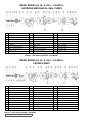
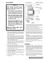
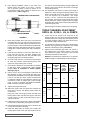
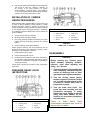
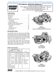
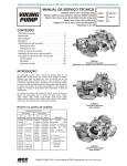
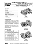
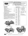
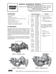
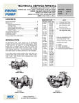
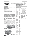
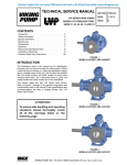
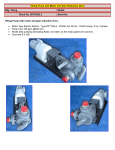
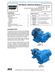
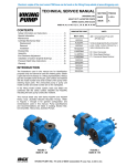
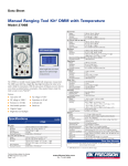
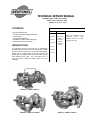
TECHNICAL SERVICE MANUAL
UNIVERSAL SEAL HEAVY DUTY PUMPS
SERIES 124A, 4124A CAST IRON
SIZES H, HL, K, KK, L, LQ, LL
CONTENTS
Mechanical Seal Pumps
Cartridge Type Optional Stuffing Box Seal
Packed Pumps
Thrust Bearing Adjustment
Installation of Carbon Graphite Bushings
Pressure Relief Valve Instructions
UNMOUNTED PUMP
PACKED
H4124A
HL124A
HL4124A
K4124A
KK4124A
L4124A
LQ4124A
LL414A
K124A
KK124A
INTRODUCTION
The illustrations used in this manual are for identification
purposes only and cannot be used for ordering parts. Obtain
a parts list from the factory or a Sentinel representative.
Always give a complete name of part, part number and
material with the model number and serial number of pump
when ordering repair parts. The unmounted pump or
pump unit model number and serial number are on the
nameplate.
MECH. SEAL
H124A
UNITS
A = Universal Seal Pump
Units are designated by the
unmounted
pump
model
numbers followed by a letter
indicating drive style.
L124A
LQ124A
LL124A
FIGURE 1 - SIZES H AND HL
FIGURE 2 - SIZES K, KK AND L
FIGURE 3 - SIZES LQ AND LL
REPAIR: MODELS H, HL, K, KK, L, LQ AND LL
CARTRIDGE MECHANICAL SEAL PUMPS
ITEM
NAME Of PART
ITEM
NAME Of PART
ITEM
NAME Of PART
1
Locknut
10
Cartridge Seal
19
Idler and Bushing Assembly
2
Lockwasher
11
Capscrew for Bracket
20
Idler Bushing
3
End Cap
12
Grease Fitting
21
Head Gasket
4
Lip Seal
13
Bracket and Bushing Assembly
22
Idler Pin
5
Bearing Spacer Collar (Outer)
14
Bracket Bushing
23
Head and Idler Pin Assembly
6
Ball Bearing
15
Bracket Gasket
24
Capscrew for Head
7
Bearing Spacer Collar (Inner)
16
Pipe Plug
25
Relief Valve Gasket
8
Ring, Half Round (Not H, HL)
17
Casing (Tapped or Flanged)
26
Internal Relief Valve
9
Bearing Housing
18
Rotor and Shaft Assembly
27
Capscrew for Valve
FIGURE 4 - EXPLODED VIEW SERIE 4124A MODEL
REPAIR: MODELS H, HL, K, KK, L, LQ AND LL
PACKED PUMPS
ITEM
NAME Of PART
ITEM
NAME Of PART
ITEM
NAME Of PART
1
Locknut
12
Packing Gland Capscrew
23
Idler and Bushing Assembly
2
Lockwasher
13
Packing
24
Idler Bushing
3
End Cap
14
Packing Retainer Washer
25
Head Gasket
4
Lip Seal
15
Capscrew for Bracket
26
Idler Pin
5
Bearing Spacer Collar (Outer)
16
Grease Fitting
27
Head and Idler Pin Assembly
6
Ball Bearing
17
Bracket and Bushing Assembly
28
Capscrew for Head
7
Bearing Spacer Collar (Inner)
18
Bracket Bushing
29
Relief Valve Gasket
8
Ring, Half Round (Not H, HL)
19
Bracket Gasket
30
Internal Relief Valve
9
Bearing Housing
20
Pipe Plug
31
Capscrew for Valve
10
Packing Gland
21
Casing (Tapped or Flanged)
11
Packing Gland Nut
22
Rotor and Shaft Assembly
FIGURE 7 - EXPLODED VIEW SERIE, 124A MODEL
G
BALL BEARING
DISASSEMBLY
BEARING HOUSING
SETSCREW
DANGER !
Before opening any Sentinel pump
liquid chamber (pumping chamber,
reservoir, relief valve adjusting cap
fitting, etc.) Be sure:
SPACER COLLAR
SHAFT
1. That any pressure in the chamber has
been completely vented through the
suction or discharge lines or other
appropriate openings or connections.
2. That the driving means (motor,
turbine, engine, etc.) has been “locked
out” or made non-operational so that
it cannot be started while work is
being done on pump.
3. That you know what liquid the
pump has been handling and the
precautions necessary to safely
handle the liquid. Obtain a material
safety data sheet (MSDS) for the
liquid to be sure these precautions
are understood.
failure
to
follow
above
listed
precautionary measures may result in
serious injury or death.
1.
SETSCREW
HALF
ROUND
RINGS
FIGURE
10
7.
Loosen two radial setscrews in flange of bearing housing
and with a spanner wrench remove the outer end cap
with closure and outer bearing spacer collar.
8.
Remove the double row ball bearing, closure and inner
bearing spacer collar from the bearing housing.
9.
Remove the rotary member of the mechanical seal from
the rotor shaft. Remove the seal seat from the bracket.
10. Clean all parts thoroughly and examine for wear and
damage. Check lip seals, ball bearing, bushings, and
idler pin and replace if necessary. Check all other
parts for nicks, burrs, excessive wear and replace if
necessary.
Remove head from pump. Do not allow idler to fall from
idler pin. Tilt top of head back when removing to prevent
this. Avoid damaging head gasket. If pump is furnished
with pressure relief valve, it need not be removed from
head or disassembled at this point. Refer to Pressure
Relief Valve Instructions, page 11.
Wash bearings in clean solvent. Blow out bearings with
compressed air. Do not allow bearings to spin; turn them
slowly by hand. Spinning bearings will damage race and
balls. Make sure bearings are clean, then lubricate with
light oil and check for roughness. Roughness can be
determined by turning outer race by hand.
If pump has jacketed head plate, it will separate from
head when it is removed. The gasket between head and
jacket head plate must be totally removed. Use new
gasket when assembling pump.
11. Casing can be checked for wear or damage while
mounted on bracket.
Remove idler and bushing assembly.
3.
Insert length of hardwood or brass through port opening
between rotor teeth to keep shaft from turning. Bend up
tang of lockwasher and with a spanner wrench, remove
locknut and lockwasher from shaft.
4.
Loosen two setscrews in the face of the bearing housing
and remove the bearing housing assembly from the
bracket. Refer to figure 10.
6.
END CAP
Mark head and casing before disassembly to insure
proper reassembly. The idler pin, which is offset in pump
head, must be positioned toward and equal distance
between port connections to allow for proper flow of
liquid through the pump.
2.
5.
LIPSEAL
Remove pair of half round rings under the inner spacer
collar from the shaft. There are no half round rings on
the “H” and “HL” size pumps.
Carefully remove rotor and shaft to avoid damaging
bracket bushing.
ASSEMBLY
1.
Install bracket bushing. If bracket bushing has a
lubrication groove, install bushing with groove at 6.00
o’clock position in bracket. If carbon graphite, Refer to
Installation of Carbon graphite Bushings, page 11.
Make sure slots in the face of the bushing are towards
rotor end of the bracket.
2.
Clean rotor shaft and seal housing bore. Make sure they
are free of dirt, grit and scratches. Gently radius leading
edge of shaft diameter over which seal is to be placed.
Never touch mechanical seal faces with anything except
clean hands or clean cloth. Minute particles can scratch
the seal faces and cause leakage.
.
3.
Place tapered installation sleeve on the shaft. Coat
tapered sleeve and inside of the rotary member
with a generous quantity of light oil. Grease is not
recommended. Start rotary member on shaft and over
tapered sleeve. Refer to figure 11.
TAPERED INSTALLATION SLEEVE
end cap into the bearing housing until tight against the
bearing. Lock in place with two set screws in the flange
of the bearing housing.
14. Put lockwasher and locknut on shaft. Insert length of
hardwood or brass through port opening between rotor
teeth to keep shaft from turning. Tighten locknut to 5070 ft.– lbs. Torque (H, HL) or 100-130 ft. – lbs. Torque
(K, KK, L, LQ, LL) . Bend one tang of lockwasher into
slot of locknut. If tang does not line up with slot, tighten
locknut until it does. Failure to tighten locknut or engage
lockwasher tang could result in early bearing failure and
cause damage to pump.
Remove length of hardwood or brass from port opening.
MECHANICAL SEAL
ROTARY MEMBER
SHAfT
THRUST BEARING ADJUSTMENT
SIZE H, HL, K, KK, L, LQ, LL PUMPS
1.
Loosen the two set screws in the outer face of the
bearing housing and turn this thrust bearing assembly
clockwise until it can no longer be turned by hand. Back
off counter-clockwise until the rotor shaft can be turned
by hand with a slight noticeable drag.
2.
For standard end clearance, back off the thrust bearing
assembly the required length measured on the outside
diameter of the bearing housing. See Table 1.
3.
Tighten the two self-locking type “Allen” set screws, in
the outboard face of the bearing housing, with equal
force against the bracket. Your pump is now set with
standard end clearances and locked.
FIGURE 11
4.
5.
Move rotary member all the way on the rotor shaft until
it is against the rotor hub. If the seal uses setscrews to
secure the seal to the shaft, tighten the setsecrews once
the seal is in place. Some PTFE seals are equipped with
holding clips which compress the seal springs. Remove
holding clips to release springs after seal is installed on
shaft.
Lubricate outer diameter of seal seat gasket with oil.
Press seal seat into bore until back, unlapped face
bottoms in bore. Make sure the seat anti-rotation pins
are aligned with slots in the bracket bushing.
6.
Coat rotor shaft and face of mechanical seal with light
oil. Start end of shaft in bracket bushing turning from
right to left, slowly pushing rotor in casing.
7.
Coat idler pin with light oil and place idler and bushing
on idler pin in head. If replacing with carbon graphite
bushing, Refer to installation of Carbon graphite
Bushings, page 11.
8.
9.
Using a .010 to .015 inch head gasket, install head and
idler assembly on pump. Pump head and casing were
marked before disassembly to insure proper reassembly.
If not, be sure idler pin, which is offset in pump head,
is positioned toward the equal distance between port
connections to allow for proper flow of liquid through
pump. If pump is equipped with jacketed headplate,
install at this time along with new gasket.
NOTE: Be sure the shaft can rotate freely. If not, back off
additional length on outside diameter and check again.
PUMP
SIZE
MODEL
TURN
BRG.
HOUSING
C.C.W.
LENGTH
ON O.D.
(Inch)
ADDITIONAL
LENGTH ON
O.D. BRG.
HOUSING
FOR
.001” END CL.
(Inch)
0.003
.75
.22
0.005
1.25
.25
STANDARD
END
CLEARANCE
(Inch)
124A
4124A
H
HL
Tighten head capscrews evenly.
10. Slide inner spacer collar over shaft with recessed end
facing rotor. H and HL size bearing spacer collars are
not recessed.
Place pair of half round rings on shaft and slide inner
bearing spacer collar over half round rings to lock them
in place. There is no pair of half round rings on the H
and HL size pumps.
11. Install the lip seal (lip toward end of shaft) in the bearing
housing and turn the bearing housing into the bracket.
12. Pack the ball bearing with grease, place on the shaft and
push or drive into place in housing.
13. Install the lipseal (with lip toward end of shaft) and
bearing spacer collar in the outer end cap and turn the
124A
4124A
K,KK
L,LQ
LL
TABLE 1
4.
High viscosity liquids required additional end clearances.
The amount of extra end clearance depends on
the viscosity of the liquid pumped. For specific
recommendations, consult the factory. Each additional
¼” turn on the outside diameter of the bearing housing is
equivalent to an extra end clearance of .001”.
INSTALLATION OF CARBON
GRAPHITE BUSHINGS
When installing carbon graphite bushings, extreme care must
be taken to prevent breaking. Carbon graphite is a brittle
material and easily cracked. If cracked, the bushing will
quickly disintegrate. Using a lubricant and adding a chamfer
on the bushing and the mating part will help in installation.
The additional precautions listed below must be followed for
proper installation.
1.
A press must be used for installation.
2.
Be certain bushing is started straight.
3.
Do not stop pressing operation until bushing is in proper
position. Starting and stopping will result in a cracked
bushing.
4.
Check bushing for cracks after installation.
VALVE - LIST Of PARTS
1.
Valve Cap
6. Valve Body
2.
Adjusting Screw
7. Valve Spring
3.
Lock Nut
8. Poppet
4.
Spring Guide
5.
Bonnet
9. Cap Gasket
10. Bonnet Gasket
FIGURE 13
SIZES K, KK, L, LQ AND LL
Carbon graphite bushings with extra interference fits are
frequently furnished for high temperature operation. These
bushings must be installed by a shrink fit.
1.
Heat bracket for idler to 750ºF.
2.
Install cool bushing with a press.
3.
If facilities are not available to reach 750ºF. temperature,
it is possible to install with 450ºF. temperature; however
the lower the temperature the greater the possibility of
cracking the bushing.
Consult factory with specific questions on high temperature
applications.
PRESSURE RELIEF VALVE
INSTRUCTIONS
DISASSEMBLY
DANGER !
Before opening any Sentinel pump
liquid chamber (pumping chamber,
reservoir, relief valve adjusting cap
fitting, etc.) Be sure:
1. That any pressure in the chamber has
been completely vented through the
suction or discharge lines or other
appropriate openings or connections.
2. That the driving means (motor,
turbine, engine, etc.) has been “locked
out” or made non-operational so that
it cannot be started while work is
being done on pump.
VALVE - LIST Of PARTS
1.
Valve Cap
2.
Adjusting Screw
6. Valve Body
7. Valve Spring
3. Lock Nut
8. Poppet
4. Spring Guide
9. Cap Gasket
5. Bonnet
3. That you know what liquid the
pump has been handling and the
precautions necessary to safely
handle the liquid. Obtain a material
safety data sheet (MSDS) for the
liquid to be sure these precautions
are understood.
Failure
to
follow
above
listed
precautionary measures may result in
serious injury or death.