1
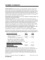
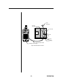
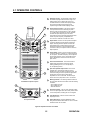
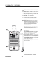
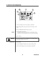
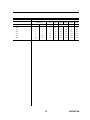
INVERTER
ARC
WELDER
MODEL 130/150/190 GTS CC/TIG
• STICK
• TIG - HIGH FREQUENCY
- LIFT START
Operating Manual
February 15, 1996
Manual No. 0-2491
TABLE OF CONTENTS
Introduction
Notes Cautions and Warnings ...................................................................... 2
Important Safety Precautions ....................................................................... 3
Publications ................................................................................................... 6
Declaration of Conformity ........................................................................... 7
Statement of Warranty .................................................................................. 8
General Information
1.1 Specifications ....................................................................................... 9
Operation
1.2
1.3
2.1
2.2
2.3
Appendix
3.0 Remote 8-Pin Connections ................................................................ 26
Transporting Methods ........................................................................ 11
Electrical Input Connections ............................................................. 12
Operator Controls ............................................................................... 15
Setup For Operation ........................................................................... 17
Operation Troubleshooting ................................................................ 24
Thermal Arc™ Model 130GTS CC/TIG, Model 150GTS CC/TIG, and
Model 190GTS CC/TIG Inverter Arc Welders
Instruction Manual Number 0-2491
Published by:
Thermal Dynamics Corporation
Industrial Park #2
West Lebanon, New Hampshire, USA 03784
© Copyright 1995
Thermal Dynamics Corporation
All rights reserved.
Reproduction of this work, in whole or in part, without written permission
of the publisher is prohibited.
While the information contained in this instruction manual represents our
best judgement, Thermal Dynamics Corporation assumes no liability for
its use.
1
INTRODUCTION
NOTES, CAUTIONS AND WARNINGS
Throughout this manual, notes, cautions, and warnings are used to
highlight important information. These highlights are categorized as
follows:
NOTE
CAUTION
WARNING
INTRODUCTION
An operation, procedure, or background information which requires
additional emphasis or is helpful in efficient operation of the system.
A procedure which, if not properly followed, may cause damage to the
equipment.
A procedure which, if not properly followed, may cause injury to the
operator or others in the operating area.
2
WARNING
IMPORTANT SAFETY PRECAUTIONS
OPERATION AND MAINTENANCE OF PLASMA ARC EQUIPMENT CAN BE
DANGEROUS AND HAZARDOUS TO YOUR HEALTH.
Operators and personnel should be alerted to ALL possible hazards. To prevent possible injury,
read, understand and follow all warnings, safety precautions and instructions before using the
equipment. Call 1-603-298-5711 or your local distributor if you have any questions.
FUMES and GASES
Fumes and Gases produced from the plasma process can be dangerous
and hazardous to your health.
• Keep all fumes and gases from your breathing area. Keep your head out
of the welding fume plume.
• Use an air-supplied respirator if available ventilation cannot remove all
fumes and gases.
• The kinds of fumes and gases from the plasma arc depend on the kind
of metal being used, coatings on the metal, and the different processes.
You must be very careful when cutting or welding any metals which may
contain one or more of the following:
Antimony
Arsenic
Barium
Beryllium
Cadmium
Chromium
Cobalt
Copper
Lead
Manganese
Mercury
Nickel
Selenium
Silver
Vanadium
• Always read the Material Safety Data Sheets (MSDS) that should be
supplied with the material you are using. These MSDS’s will give you the
information regarding the kind and amount of fumes and gases that may
be dangerous to your health.
• For information on how to test for fumes and gases in your workplace,
refer to item #1 and related publictions on page 6.
• Use special equipment, such as water or down draft cutting tables, to
capture fumes and gases.
• Do not use the plasma torch in an area where combustible or explosive
gases or materials are located.
• Phosgene, a toxic gas, is generated from the vapors of chlorinated
solvents and cleansers. Remove all sources of these vapors.
3
INTRODUCTION
IMPORTANT SAFETY PRECUATIONS (CONTINUED)
ELECRTIC SHOCK
Electric Shock can injure or kill. The plasma arc process uses and produces high
voltage electrical energy. This electric energy can cause severe or fatal shock to
the operator or others in the workplace.
• Never touch any parts that are electrically “live” or “hot”, wear dry gloves
and clothing. Insulate yourself from the work piece or other parts of the
welding circuit.
• Repair or replace all worn or damaged parts.
• Extra care must be taken when the workplace is moist or damp.
• Install and maintain equipment according to NEC code, see page iv, item 9.
• Disconnect power source before performing any service or repairs.
• Read and follow all the instructions in the Operators Manual.
FIRE AND EXPLOSION
Fire and Explosions can be caused by hot slag, sparks, or the plasma arc. The
plasma arc process produces hot sparks, slag and metal which can ignite
combustible material, or cause flammable vapors to explode.
• Be sure there is no combustible or flammable material in the workplace. Any
material that cannot be removed must be protected.
• Ventilate all flammable or explosive vapors from the workplace.
• Do not cut or weld on containers that may have held combustibles.
• Provide a fire watch when working in an area where fire hazards may exist.
PLASMA ARC RAYS
Plasma Arc Rays can injure your eyes and burn your skin. The plasma arc
process produces very bright ultra violet and infra red light. These arc rays will
damage your eyes and burn your skin if you are not properly protected.
• To protect your eyes, always wear a welding helmet or shield. Also always
wear safety glasses with side shields, goggles or other protective eye wear.
• Wear welding gloves and suitable clothing to protect your skin from the arc
rays and sparks.
• Keep helmet and safety glasses in good condition. Replace lenses when
cracked, chipped or dirty.
• Protect others in the work area from the arc rays. Use protective booths,
screens or shields.
• Use the shade of lens as recommended in the operators manual.
INTRODUCTION
4
IMPORTANT SAFETY PRECAUTIONS (CONTINUED)
NOISE
Noise can cause permanent hearing loss. Plasma arc processes can cause noise
levels to exceed safe limits. You must protect your ears from loud noise to
prevent permanent loss of hearing.
• To protect your hearing from loud noise, wear protective ear plugs and/or
ear muffs. Protect others in the workplace.
• Noise levels should be measured to be sure the decibels (sound) do not
exceed safe levels.
• For information on how to test for noise, see item 1, page 6.
5
INTRODUCTION
PUBLICATIONS
Refer to the following standards or their latest revisions for more information:
1.
OSHA, SAFETY AND HEALTH STANDARDS, 29CFR 1910, obtainable from the Superintendent of
Documents, U.S. Government Printing Office, Washington, D.C. 20402
2.
ANSI Standard Z49.1, SAFETY IN WELDING AND CUTTING, obtainable from the American
Welding Society, 550 N.W. LeJeune Rd, Miami, FL 33126
3.
NIOSH, SAFETY AND HEALTH IN ARC WELDING AND GAS WELDING AND CUTTING,
obtainable from the Superintendent of Documents, U.S. Government Printing Office, Washington,
D.C. 20402
4.
ANSI Standard Z87.1, SAFE PRACTICES FOR OCCUPATION AND EDUCATIONAL EYE AND
FACE PROTECTION, obtainable from American National Standards Institute, 1430 Broadway,
New York, NY 10018
5.
ANSI Standard Z41.1, STANDARD FOR MEN’S SAFETY-TOE FOOTWEAR, obtainable from the
American National Standards Institute, 1430 Broadway, New York, NY 10018
6.
ANSI Standard Z49.2, FIRE PREVENTION IN THE USE OF CUTTING AND WELDING
PROCESSES, obtainable from American National Standards Institute, 1430 Broadway, New York,
NY 10018
7.
AWS Standard A6.0, WELDING AND CUTTING CONTAINERS WHICH HAVE HELD
COMBUSTIBLES, obtainable from American Welding Society, 550 N.W. LeJeune Rd, Miami, FL
33126
8.
NFPA Standard 51, OXYGEN-FUEL GAS SYSTEMS FOR WELDING, CUTTING AND ALLIED
PROCESSES, obtainable from the National Fire Protection Association, Batterymarch Park, Quincy,
MA 02269
9.
NFPA Standard 70, NATIONAL ELECTRICAL CODE, obtainable from the National Fire Protection
Association, Batterymarch Park, Quincy, MA 02269
10. NFPA Standard 51B, CUTTING AND WELDING PROCESSES, obtainable from the National Fire
Protection Association, Batterymarch Park, Quincy, MA 02269
11. CGA Pamphlet P-1, SAFE HANDLING OF COMPRESSED GASES IN CYLINDERS, obtainable
from the Compressed Gas Association, 1235 Jefferson Davis Highway, Suite 501, Arlington, VA
22202
12. CSA Standard W117.2, CODE FOR SAFETY IN WELDING AND CUTTING, obtainable from the
Canadian Standards Association, Standards Sales, 178 Rexdale Boulevard, Rexdale, Ontario,
Canada M9W 1R3
13. NWSA booklet, WELDING SAFETY BIBLIOGRAPHY obtainable from the National Welding
Supply Association, 1900 Arch Street, Philadelphia, PA 19103
14. American Welding Society Standard AWSF4.1, RECOMMENDED SAFE PRACTICES FOR THE
PREPARATION FOR WELDING AND CUTTING OF CONTAINERS AND PIPING THAT HAVE
HELD HAZARDOUS SUBSTANCES, obtainable from the American Welding Society, 550 N.W.
LeJeune Rd, Miami, FL 33126
15. ANSI Standard Z88.2, PRACTICE FOR RESPIRATORY PROTECTION, obtainable from American
National Standards Institute, 1430 Broadway, New York, NY 10018
INTRODUCTION
6
DECLARATION OF CONFORMITY
Manufacturer: Thermal Dynamics Corporation
Address:
Industrial Park #2
West Lebanon, New Hampshire 03784
USA
The equipment described in this manual conforms to all applicable aspects and regulations of the
‘Low Voltage Directive’ (European Council Directive 73/23/EU, as recently changed in Directive
93/63/EU) and to the National legislation for the enforcement of this Directive.
The equipment described in this manual conforms to all applicable aspects and regulations of the
“EMC Directive” (European Council Directive 89/336/EEC) and to the National legislation for
the enforcement of this Directive.
Serial numbers are unique with each individual piece of equipment and details description, parts
used to manufacture a unit and date of manufacture.
National Standard and Technical Specifications
The product is designed and manufactured to a number of standards and technical requirements
among them are:
* CSA (Canadian Standards Association) standard C22.2 number 60-M1990 for Arc welding
equipment.
* UL (Underwriters Laboratory) rating 94VO flammability testing for all printed-circuit boards
used.
* CENELEC EN50199 EMC Product Standard for Arc Welding Equipment March 1995.
* IEC 974-1 (BS 638-PT10) (EN 60 974-1) applicable to welding equipment and associated
accessories.
* Extensive product design verification is conducted at the manufacturing facility as part of the
routine design and manufacturing process, to ensure the product is safe and performs as
specified. Rigorous testing is incorporated into the manufacturing process to ensure the
manufactured product meets or exceeds all design specifications.
Thermal Dynamics has been manufacturing products that perform in a safe manner for more
than 30 years and will continue to achieve excellence in our area of manufacture.
Manufacturers responsible representative: David Ashworth
Vice President & Managing Director
Thermadyne Europe
Chorley England
7
INTRODUCTION
STATEMENT OF WARRANTY
LIMITED WARRANTY: Thermal Dynamics Corporation (hereinafter “Thermal”) warrants that its
products will be free of defects in workmanship or material. Should any failure to conform to this
warranty appear within the time period applicable to the Thermal products as stated below, Thermal
shall, upon notification thereof and substantiation that the product has been stored, installed, operated,
and maintained in accordance with Thermal’s specifications, instructions, recommen dations and
recognized standard industry practice, and not subject to misuse, repair, neglect, alteration, or accident,
correct such defects by suitable repair or replacement, at Thermal’s sole option, of any components or
parts of the product determined by Thermal to be defective.
THIS WARRANTY IS EXCLUSIVE AND IS IN LIEU OF ANY WARRANTY OF MERCHANTABILITY OR
FITNESS FOR A PARTICULAR PURPOSE.
LIMITATION OF LIABILITY: Thermal shall not under any circumstances be liable for special or
consequential damages, such as, but not limited to, damage or loss of purchased or replacement goods,
or claims of customers of distributor (hereinafter “Purchaser”) for service interruption. The remedies of
the Purchaser set forth herein are exclusive and the liability of Thermal with respect to any contract, or
anything done in connection therewith such as the performance or breach thereof, or from the
manufacture, sale, delivery, resale, or use of any goods covered by or furnished by Thermal whether
arising out of contract, negligence, strict tort, or under any warranty, or otherwise, shall not, except as
expressly provided herein, exceed the price of the goods upon which such liability is based.
THIS WARRANTY BECOMES INVALID IF REPLACEMENT PARTS OR ACCESSORIES ARE USED
WHICH MAY IMPAIR THE SAFETY OR PERFORMANCE OF ANY THERMAL PRODUCT.
THIS WARRANTY IS INVALID IF THE PRODUCT IS SOLD BY NON-AUTHORIZED PERSONS.
The limited warranty periods for Thermal products shall be as follows: A maximum of three (3) years
from date of sale to an authorized distributor and a maximum of two (2) years from date of sale by such
distributor to the Purchaser, and with the following further limitations on such two (2) year period:
PAK UNITS, POWER SUPPLIES
PARTS
LABOR
MAIN POWER MAGNETICS ....................................... 2 YEARS .................. 1 YEAR
ORIGINAL MAIN POWER RECTIFIER ...................... 2 YEARS .................. 1 YEAR
CONTROL PC BOARD .................................................. 2 YEARS .................. 1 YEAR
ALL OTHER CIRCUITS AND COMPONENTS .......... 1 YEAR ................... 1 YEAR
INCLUDING, BUT NOT LIMITED TO, STARTING
CIRCUIT, CONTACTORS, RELAYS, SOLENOIDS,
PUMPS, POWER SWITCHING SEMI-CONDUCTORS
CONSOLES, CONTROL EQUIPMENT, HEAT ................. 1 YEAR ................... 1 YEAR
EXCHANGES, AND ACCESSORY EQUIPMENT
TORCH AND LEADS ..................................................... 180 DAYS ................ 180 DAYS
REPAIR/REPLACEMENT PARTS ....................................... 90 DAYS .................. 90 DAYS
Warranty repairs or replacement claims under this limited warranty must be submitted by an
authorized Thermal Arc® repair facility within thirty (30) days of the repair. Authorized Thermal Arc®
repair facilities are authorized distributors and authorized Thermal Arc® Service Centers. No
transportation costs of any kind will be paid under this warranty. Transportation charges to send
products to an authorized warranty repair facility shall be the responsibility of the customer. All
returned goods shall be at the customer’s risk and expense. This warranty supersedes all previous
Thermal warranties.
Thermal Arc® is a Registered Trademark of Thermal Dynamics
8
INFORMATION
Effective January 18, 1991
1.1 SPECIFICATIONS
Description
The Thermal Arc™ Model 130GTS, Model 150GTS, and Model 190GTS are
single-phase DC arc welding power sources with Constant Current (CC)
output charactaeristics. Each unit is equipped with a gas control solenoid,
lift start TIG, and high-frequency arc starter for use with Gas Tungsten Arc
Welding (GTAW). These units are designed for use with Shielded Metal
Arc Welding (SMAW), Gas Tungsten Arc Welding -Lift Start (GTAW-LS)
and Gas Tungsten Arc Welding -Pulsed (GTAW-P) -Sloped (GTAW-S)
processes.
Arc Characteristics
"CURRENT" Control
VOLTS
19
5
AMPS
A-00032
130
Figure 1. Model 130 GTS CC/TIG Volt-Ampere Curves
Arc Characteristics
"CURRENT" Control
VOLTS
19
5
A-00032
AMPS
150
Figure 2. Model 150 GTS CC/TIG Volt-Ampere Curves
Arc Characteristics
"CURRENT" Control
VOLTS
19
5
A-00032
AMPS
190
Figure 3. Model 190 GTS CC/TIG Volt-Ampere Curves
NOTE
Volt-Ampere curves show the voltage and Amperage output capabilities
of the welding power source. Curves of other settings will fall between the
curves shown.
9
GENERAL INFORMATION
1.1 SPECIFICATIONS
Parameter/Model
Rated Output
Amperes
Volts
Duty Cycle
@ 230 V Input
@ 115 V Input
Range (Min. - Max.)
Amperes
@ 230 V Input
@ 115 V Input
Volts
Over Current Voltage
Maximum OCV
Input Data
Dimensions/Weight
Width
Height
Length
Weight (with Cable)
Output At Rated Load
Input data 50/60 Hz/Duty Cycle
208 VAC 1-Phase
230 VAC 1-Phase
115 VAC 1-Phase
Output At No Load
Input data 50/60 Hz/Duty Cycle
208 VAC 1-Phase
230 VAC 1-Phase
115 VAC 1-Phase
Model 130 GTS CC/TIG
@ 230 V
@ 115V
130
85
15
Model 150 GTS CC/TIG
@ 230 V
@ 115V
150
85
13
16
13
Model 190 GTS CC/TIG
@ 230 V
@ 115V
190
95
18
13
40% at 130 A/15 V
25% at 100 A/25 V
40% at 85 A/13 V
25% at 85 A/23 V
40% at 150 A/16 V
25% at 200 A/25 V
40% at 85 A/13 V
25% at 85 A/23 V
25% at 190 A/17 V
25% at 150 A/26V
40% at 95 A/14 V
25% at 95 A/24 V
5-130
5-85
10-25
5-150
5-85
10-26
5-190
5-95
10-28
64 V
50/60 Hz
64 V
50/60 Hz
64 V
50/60 Hz
5.1 in (130mm)
9.5 in (240mm)
11.8 in (300mm)
18.7 lb.(8.5 kg.)
5.1 in (130mm)
9.5 in (240mm)
11.8 in (300mm)
18.7 lb.(8.5 kg.)
5.1 in (130mm)
9.5 in (240mm)
11.8 in (300mm)
18.7 lb.(8.5 kg.)
40% at 130 A/15 V
17.5 A / 3.6 KVA / 2.3 KV
40% at 150 A/16 V
21.5 A / 4.5 KVA / 2.8 KV
40% at 150A/17V
29.0 A / 6.0 KVA / 3.8 KV
25% at 100 A/24 V
21.5 A / 4.5 KVA / 2.8 KV
25% at 120 A/25 V
27.0 A / 5.6 KVA / 3.5 KV
25% at 150 A/26 V
35.0 A / 7.3 KVA / 3.5 KV
40% at 130 A/15 V
16.0 A / 3.6 KVA / 2.3 KV
40% at 150 A/16 V
19.5 A / 4.5 KVA / 2.8 KV
40% at 150A/17V
26.0 A / 6.0 KVA / 2.8 KV
25% at 100 A/24 V
19.5 A / 4.5 KVA / 2.8 KV
25% at 120 A/25 V
27.0 A / 5.6 KVA / 3.5 KV
25% at 150 A/26 V
32.0 A / 7.3 KVA / 4.6 KV
40% at 85 A/13 V
18.0 A / 2.1 KVA / 1.3 KV
40% at 85 A/13 V
18.0 A / 2.1 KVA / 1.3 KV
40% at 85 A/14 V
21.5 A / 2.5 KVA / 1.6 KV
25% at 85 A/23 V
32.0 A / 3.6 KVA / 2.3 KV
25% at 85 A/23 V
32.0 A / 3.6 KVA / 2.3 KV
25% at 95 A/24 V
37.0 A / 4.2 KVA / 2.7 KV
40% at 130 A/15 V
2.5 A / 0.5 KVA / 0.3 KV
40% at 150 A/16 V
2.5 A / 0.5 KVA / 0.3 KV
40% at 150 A/17 V
2.5 A / 0.5 KVA / 0.3 KV
25% at 100 A/24 V
2.5 A / 0.5 KVA / 0.3 KV
25% at 120 A/25 V
2.5 A / 0.5 KVA / 0.3 KV
25% at 150 A/26 V
2.5 A / 0.5 KVA / 0.3 KV
40% at 130 A/15 V
2.0 A / 0.5 KVA / 0.3 KV
40% at 150 A/16 V
2.0 A / 0.5 KVA / 0.3 KV
40% at 150 A/17 V
1.0 A / 0.5 KVA / 0.3 KV
25% at 100 A/24 V
2.0 A / 0.5 KVA / 0.3 KV
25% at 120 A/25 V
1.0 A / 0.5 KVA / 0.3 KV
25% at 150 A/26 V
1.0 A / 0.5 KVA / 0.3 KV
40% at 85 A/13 V
1.0 A / 0.5 KVA / 0.3 KV
40% at 85 A/13 V
1.0 A / 0.5 KVA / 0.3 KV
40% at 85 A/14 V
1.0 A / 0.5 KVA / 0.3 KV
25% at 85 A/23 V
1.0 A / 0.5 KVA / 0.3 KV
25% at 85 A/23 V
1.0 A / 0.5 KVA / 0.3 KV
25% at 95 A/24 V
1.0 A / 0.5 KVA / 0.3 KV
GENERAL INFORMATION
10
1.2 TRANSPORTING METHODS
These units are equipped with one handle and a shoulder strap for
carrying purposes.
WARNING
ELECTRIC SHOCK can kill.
• DO NOT TOUCH live electrical parts.
• Disconnect input power conductors from de-energized supply line
before moving welding power source.
WARNING
FALLING EQUIPMENT can cause serious personal injury and equipment
damage.
• Lift unit with handle or shoulder strap on top of case.
• Use hand cart or similar device of adequate capacity.
• If using a fork lift vehicle, place and secure unit on a proper skid
before transporting.
• This unit has a built-in handle and shoulder strap on top of case for
lifting. Be sure unit is lifted and transported safely and securly.
11
OPERATION
1.3 ELECTRICAL INPUT CONNECTIONS
WARNING
ELECTRIC SHOCK can kill; SIGNIFICANT DC VOLTAGE is present after
removal of input power.
• DO NOT TOUCH live electrical parts.
• SHUT DOWN welding power source, disconnect input power
employing lockout/tagging procedures, wait 60-80 seconds, and
measure voltage on input capacitors according to instruction manual
before touching any parts. Lockout/tagging procedures consist of
padlocking line disconnect switch in open position, removing fuses
from fuse box, or shutting off and red-tagging circuit breaker or
other disconnecting device.
Electrical Input
Requirements
Operate the welding power source from a single-phase 50/60 Hz, AC
power supply. The input voltage must match one of the electrical input
voltages shown on the input data label on the unit nameplate. Contact the
local electric utility for information about the type of electrical service
available, how proper connections should be made, and inspection
required.
The line disconnect switch provides a safe and convenient means to
completely remove all electrical power from the welding power supply
whenever necessary to inspect or sevice the unit.
NOTE
These units are equipped with a two-conductor with earth power cable
that is connected at the welding power source end for single-phase
electrical input power.
• Do not connect an input conductor to the ground terminal.
European models have brown (line 1) and blue (line 2) conductors,
all others have white (line 2) and black (line 1).
• Do not connect the ground conductor to an input line terminal.
European models have yellow/green ground conductor, all others
have green.
Refer to Figure 4 and:
1) Connect end of ground conductor to a suitable ground. Use a
grounding method that complies with all applicable electrical codes.
2) Connect ends of line 1 and line 2 input conductors to a de-energized
line disconnect switch.
3) Use Table 1 on Page 20 as a guide to select line fuses for the
disconnect switch.
OPERATION
12
Earth
Conductor
Ground
Terminal
Line Fuse
Line
Disconnect
Switch
Line 1
Line 2
Ground
Primary Power Cable
Welding Power Supply
Figure 4. Electrical Input Connections
13
OPERATION
Voltage Selection
The input voltage must match one of the electrical input voltages shown
on the input data label on the unit nameplate.
This power source incorporates a control circuit which automatically links
the power source to the primary input voltage and adjusts it to allow for
operation of the unit within the input rating on the input data tag. It is not
necessary to manually switch (terminals or links) if the unit is moved to a
new location and a different input power is selected.
• The surge current prevention circuit becomes activated when the
PRIMARY POWER switch is turned ON.
• About two seconds after power on, the control circuit detects the
input voltage and automatically selects the correct circuits for
operation.
• The welding power source is ready for operation within five seconds
after power is turned on.
OPERATION
14
2.1 OPERATOR CONTROLS
16
1
Amperage Control - The Amperage Control selects
the desired amperage within the entire range of the
welding power source. Rotating this control in a
clockwise direction increases the amperage output.
The scale surrounding the amperage control
represents approximate actual amperage values.
2
Pulse Frequency Control - The Pulse Frequency
control provides a means of selecting the pulse
frequency when the Pulse switch is in the H (HIGH)
or L (LOW) position. Rotating the control clockwise
increases the pulse frequency.The two scales
surrounding the control represent approximate actual
values.The pulse frequency is adjustable from
0.5 to 25 Hz in LOW and 10 to 500 Hz in HIGH.
3
Sloper Switch - When in the OFF position the Sloper
is inactive. Selecting the ON position activates the
Sloper. Selecting the SPOT position activates the
spot welding timer. The Slope sequence and spot
modes are activated by a remote ON/OFFswitch
connected to the 8-pin receptacle. See the section on
Slope sequence.
4
Pulser Switch - When in the OFF position the Pulser
is inactive. Selecting H (HIGH) or L (LOW) will activate
the TIG pulser. The Pulse Frequency can be adjusted
by the Pulse Frequency control. Pulse width is fixed
at 50%. Background current is fixed at 1/5th of the
peak current.
5
Process Selector Switch - The Process Selector
Switch allows the operator to select the STICK
welding (SMAW) process, LIFT TIG (GTAW) or
HF TIG (GTAW) process.
6
Spot Time Up/Down Slope Control - This control
provides Spot, Up and Down slope time control.
Rotating the control clockwise increases the time. The
scale surrounding the control represents approximate
actual values. The Spot and Up slope time is
adjustable from 0.5 to 5 seconds. The Down slope
time is twice the Up slope time at 0.5 to 10 seconds.
7
Warning Indicator - The Warning Indicator located on
the front panel will become activated under the following
conditions:
• Input voltage is too low
• Input voltage too high
• Thermal overload
8
AC Power Indicator - The AC Power Indicator located
on the front panel lights when the Primary Power Switch
is in the ON position, indicating the unit is energized.
9
8-pin Receptacle - Used for remote contactor and
amperage controls.
6
1
2
1
20
50
20
0
0.5
50
25
5
50
0
13
STICK/TIG
HOT START
A
sec
UP SLOPE
SPOT TIME
DOWN SLOPE (x2)
SLOPER
PULSER
H
8
ON
WARNING
OFF
L
5
A
230V INPUT
OFF
LIFT
START
4
115V INPUT
10
0
0.5
10
TIG
7
3
80
STICK
HF
START
2
120
L
H
HZ
PULSE FREQ
0
5
50
4
50
40
50
20
400
5
80
50
40
15
10
100
60
300
0
20
0
10
3
8
9
SPOT
POWER
R
130GTS
10
11
GAS OUTPUT
12
All Models Except European
10
11
GAS OUTPUT
12
European Models
10
Output Gas Fitting - European Model Gas output
fitting size 3/8" BSP for Monocable TIG Torch. All other
models have 5/8"-18 unf female.
Figure 5a. Operator Controls -Front Panel
15
OPERATION
2.1 OPERATOR CONTROLS
11
Positive Terminal - 25mm DIN-style female receptacle.
12
Negative Terminal - 25mm DIN-style female receptacle.
13
Primary Power Switch - Placing the Primary Power
Switch (circuit breaker) located on the rear panel to the
ON position energizes the welding power source.
14
Input Cable - 10 feet; size 12/3 cable
15
Input Gas Fitting - The input gas connection is located
on the bottom center of the rear panel. European
models have 3/8" BSP fitting, all others have 5/8" -18
unf female.
16
Hot Start Control - The Hot Start Control operates in
the STICK and HF TIG modes. The Hot Start time is
approximately 0.01 seconds in TIG and 0.06 seconds
in STICK. The current value is adjusted from 0 to 100
Amps over the determined weld current set by the
Amperage Control. Rotating the control clockwise
increases Hot Start current.
Gas Solenoid - The pre-flow is fixed at 150 ms. Postflow is automatically adjusted from 1 to 15 seconds by
the position of the welding Amperage Control.
13
14
PRIMARY POWER
OFF
1
f1
f2
ON
Sloper Sequence A. Remote ON/OFF switch closed - Pre-flow starts to
flow. In HF TIG mode HF and initial current is present
after pre-flow. (In LIFT TIG mode HF is not present.)
Initial current is 1/5th of the welding current.
PRIMARY CABLE
IEC974
B. Remote ON/OFF switch opened - Current increases
to welding current at the rate set by the UP/DOWN Slope
control. Welding current is set by the Amperage Control.
5A/10V - 130A/25V
U
V
64
U
40%
25%
40%
25%
I
130A
100A
85A
85A
15V
24V
13V
23V
N/A
17.5A
N/A
21.5A
19.5A
18A
N/A
N/A
32A
N/A
N/A
THERMADYNE
Thermal Dynamics
WEST LEBANON, NEW HAMPSHIRE USA 03784
MADE IN JAPAN
130GTS
V
115V
208V
1
X
U
230V
50/60 Hz
16A
3.6 kVA 4.5 kVA 2.1 kVA 3.6 kVA
S
IP 23S
TURN OFF YOUR MAIN POWER SOURCE AND
CIRCUIT BREAKER OF THIS WELDER BEFORE
MAINTENANCE OR INSPECTION
C. Remote ON/OFF switch closed - Current decreases
to final current at twice the rate set for UP Slope. Final
current is 1/5th of welding current.
D. Remote ON/OFF switch opened - Arc shuts off and
post-flow time initiated.
15
GAS INPUT
E
Figure 5b. Operator Controls -Rear Panel
OPERATION
16
2.2 SETUP FOR OPERATION
Shielded Metal Arc Welding (SMAW)
Read and follow all safety precautions on pages 2-3 of this manual before
preceeding with operation.
1. Install and connect unit according to the installation instructions in
section 1.3 of this manual.
2. Wear dry insulating gloves and clothing.
3. Connect work clamp to clean, bare metal at workpiece.
4. Select propor electrode.
5. Refer to Operator Control section and set the controls per the
following:
a. PROCESS SELECTOR switch [5] to STICK position.
b. Rotate the AMPERAGE control [1] to output current level
desired.
1
40
1
20
50
20
0
0.5
50
25
5
50
0
STICK/TIG
HOT START
A
sec
UP SLOPE
SPOT TIME
DOWN SLOPE (x2)
SLOPER
PULSER
H
8
ON
WARNING
OFF
L
5
A
230V INPUT
OFF
LIFT
START
4
0.5
10
TIG
115V INPUT
10
0
0
STICK
HF
START
3
80
L
H
HZ
PULSE FREQ
2
120
50
5
50
40
50
20
400
5
80
50
0
10
15
10
100
60
300
0
20
13
WARNING
SPOT
POWER
R
130GTS
6. Insert electrode into electrode holder.
7. Wear welding helmet with proper filter lens according to ANSI
Z49.1.
8. Place the PRIMARY POWER switch [13] to ON.
9. Begin welding.
17
OPERATION
2.2 SETUP FOR OPERATION
Gas Tungsten Arc Welding (GTAW) High Frequency/Lift Start
WARNING
Read and follow all safety precautions on pages 2-3 of this manual before
preceeding with operation.
1. Install and connect unit according to the installation instructions in
section 1.3 of this manual.
2. Connect TIG torch to proper output receptacle.
3. Select proper tungsten electrode (refer to Electrode Selection Table 2,
Page 22).
4. Prepare tungsten electrode and insert into torch.
5. Wear dry insulating gloves and clothing.
6. Connect remote control device to 8-Pin receptacle.
7. Connect work clamp to clean, bare metal at workpiece.
8. Refer to Operator Control section and set the controls per the
following:
a. PROCESS SELECTOR switch [5] to desired Gas Tungsten Arc
Welding position. (LIFT or HF Start)
b. Rotate the AMPERAGE control [1] to output current level
desired.
2
1
40
1
20
50
20
3
0
SLOPER
PULSER
H
sec
UP SLOPE
SPOT TIME
DOWN SLOPE (x2)
8
ON
WARNING
OFF
L
0.5
50
25
5
50
13
STICK/TIG
HOT START
A
5
A
230V INPUT
OFF
LIFT
START
4
115V INPUT
10
0
0.5
10
TIG
80
0
STICK
HF
START
3
120
L
H
HZ
PULSE FREQ
2
0
50
5
50
40
50
20
400
5
80
50
10
15
10
100
60
300
0
20
0
4
6
SPOT
POWER
R
130GTS
9. Turn on shielding gas.
10. Wear welding helmet with proper filter lens according to ANSI
Z49.1.
OPERATION
18
11. Place the PRIMARY POWER switch [13] to ON.
NOTES
12. Activate remote control device.
a. In LIFT TIG mode, touch electrode to work and lift to start arc.
b. In HF TIG mode, high frequency will start, followed by welding
arc.
13. Begin welding.
WARNING
HIGH CONCENTRATION OF SHIELDING GAS can impair health or
kill. Shut off gas supply when not in use.
19
OPERATION
2.2 SETUP FOR OPERATION
Gas Tungsten Arc Welding -Pulsed (GTAW-P) -Sloped (GTAW-S) -TIG Spot
WARNING
Read and follow all safety precautions on pages 2-3 of this manual before
preceeding with operation.
1. Install and connect unit according to the installation instructions in
section 1.3 of this manual.
2. Select proper tungsten electrode (refer to Electrode Selection Table 2,
Page 22).
3. Prepare tungsten electrode and insert into torch.
4. Wear dry insulating gloves and clothing.
5. Connect remote control device to 8-Pin receptacle.
6. Connect work clamp to clean, bare metal at workpiece.
7. Refer to Operator Control section and set the controls per the
following:
I. PROCESS SELECTOR switch [5] to desired gas tungsten arc
welding position. LIFT or HF TIG.
A. PULSE TIG welding
1. PULSER SELECTOR switch [4] to desired frequency pulse
of high or low.
2. Rotate the AMPERAGE control [1] to desired output
current level.
3. Rotate PULSE FREQUENCY control [2] to desired
frequency position.
B. SLOPE TIG welding
1. SLOPER switch [3] to SLOPE position.
2. Rotate AMPERAGE control [1] to desire welding current
level.
3. Rotate SPOT TIME UP/DOWN SLOPE control [6] to
desired UP/DOWN slope time.
NOTE: Use a remote ON/OFF switch to control SLOPE
sequence. See Operator Control section page 15.
C. SPOT TIG welding
1. SLOPER switch [3] to SPOT position.
2. Rotate AMPERAGE control [1] to desired spot welding
current level.
3. Rotate SPOT TIME UP/DOWN SLOPE control [6] to
desired SPOT welding time.
OPERATION
20
2.2 SETUP FOR OPERATION
2
1
40
1
20
50
20
3
0
SLOPER
PULSER
H
sec
UP SLOPE
SPOT TIME
DOWN SLOPE (x2)
8
ON
WARNING
OFF
L
0.5
50
25
5
50
13
STICK/TIG
HOT START
A
5
A
230V INPUT
OFF
LIFT
START
4
115V INPUT
10
0
0.5
10
TIG
80
0
STICK
HF
START
3
120
L
H
HZ
PULSE FREQ
2
0
50
5
50
40
50
20
400
5
80
50
10
15
10
100
60
300
0
20
0
4
6
SPOT
POWER
R
130GTS
8. Turn on shielding gas and water supplies as applicable.
9. Wear welding helmet with proper filter lens according to ANSI
Z49.1.
10. Place the PRIMARY POWER switch [13] to ON.
NOTES
11. Activate remote control device.
a. In LIFT TIG mode, touch electrode to work and lift to start arc.
b. In HF TIG mode, high frequency will start, followed by welding
arc.
12. Begin welding.
WARNING
Shutting Down
HIGH CONCENTRATION OF SHIELDING GAS can impair health or
kill. Shut off gas supply when not in use.
13. Stop welding.
14. Move the PRIMARY POWER switch [13] to the OFF position.
15. Turn off the shielding gas and water supplies if applicable.
21
OPERATION
Table 1 Fuse Size Selection
Input Power/Input Voltage
Single-Phase
208-230 VAC
115 VAC
NOTE
NOTE
Model 130GTS
30
Fuse Size (Amperes)
Model 150GTS
30
Model 190GTS
40
25
25
30
Continuous output on 115VAC/20 Amp circuit breaker for fuse: 92 Amps/
13 Vdc (TIG), 51 Amps/23 Vdc (Stick)
Fuse size is based on not more than 200 percent of the rated input
amperage of the welding power source (Based on Article 630, National
Electrical Code)
Table 2 Electrode Selection Table
Electrode/Diameter
Amperage Range
DC-Argon Electrode
Negative/Straight Polarity
DC-Argon Electrode
Positive/ReversePolarity
Pure Tungsten
(Green Band)
0.010 in. (0.25mm)
1-15
—
0.020 in. (0.51mm)
5-20
—
0.040 in. (1.02mm)
15-80
—
1/16 in. (1.59mm)
70-150
10-20
3/32 in. (2.38mm)
125-225
15-20
1/8 in. (3.18mm)
225-360
25-40
5/32 in. (3.97mm)
360-450
40-55
3/16 in. (4.76mm)
450-720
55-80
1/4 in. (6.35mm)
720-950
80-125
1-25
—
15-40
—
2% Thorium Alloyed Tungsten
(Red Band)
0.010 in. (0.25mm)
0.020 in. (0.51mm)
0.040 in. (1.02mm)
25-85
—
1/16 in. (1.59mm)
50-160
10-20
3/32 in. (2.38mm)
135-235
15-30
1/8 in. (3.18mm)
250-400
25-40
5/32 in. (3.97mm)
400-500
40-55
3/16 in. (4.76mm)
500-750
55-80
1/4 in. (6.35mm)
750-1,000
80-125
OPERATION
22
Table 3 Weld Cable Size
Duty Cycle
Welding Amperes
100
Maximum Total Cable Length in Weld Circuit
Under 100 ft.
150 ft.
200 ft.
250 ft.
300 ft.
(Under 30m)
(45m)
(60m)
(70m)
(90m)
100-60%
60-100%
10-100%
350 ft.
(105m)
400 ft.
(120m)
1/0
4
4
4
3
2
1
1/0
150
3
3
2
1
1/0
2/0
3/0
3/0
200
3
2
1
1/0
2/0
3/0
4/0
4/0
250
2
1
1/0
2/0
3/0
4/0
2-2/0
2-2/0
300
1
1/0
2/0
3/0
4/0
2-2/0
2-3/0
2-3/0
400
1/0
2/0
3/0
4/0
2-2/0
2-3/0
2-4/0
2-4/0
23
OPERATION
2.3 OPERATION TROUBLESHOOTING
General
WARNING
Basic Troubleshooting
Troubleshooting and repairing this unit is a process which should be
undertaken only by those familiar with high voltage, high power electronic
equipment.
There are extremely dangerous voltage and power levels present inside
this unit. Do not attempt to diagnose or repair unless you have had train–
ing in power electronics measurement and troubleshooting techniques.
This manual covers a basic level of troubleshooting that requires limited
disassembly and measurements. It is helpful for solving many of the
common problems that can arise with the Inverter Arc Welder system.
If major complex subassemblies are faulty, the unit must be returned to an
authorized sevice center for repair.
Follow all instructions as listed and complete each section in the order
presented.
NOTE
For major troubleshooting and parts replacement procedures, please refer
to the appropriate Inverter Arc Welder Service Manual:
Model 130GTS CC/TIG
Model 150GTS CC/TIG
Model 190GTS CC/TIG
How to Use This Guide
Service Manual 0-2493
Service Manual 0-2493
Service Manual 0-2493
The following information is a guide to help you determine the most likely
causes for various symptoms.
This guide is set up in the following manner:
A. Symptom (Bold Type)
Any special instructions (Text Type)
1. Cause (Italic Type)
a. Check/Remedy (Text Type)
Locate your symptom, check the cause(s) (the simplest or most likely is
listed first), then perform the remedy given. Repair as needed being sure
to verify that the unit is fully operational after any repairs.
Specific Problems
OPERATION
A. No weld output; unit is completely inoperative
1. Line disconnect switch is in OFF position
a. Place line disconnect switch in ON position.
2. Line fuse(s) open
a. Check and replace line fuse(s).
3. Improper electrical input connections
a. See Section 1.3 Electrical Input Requirements for proper
input connections
4. PRIMARY POWER switch Main Circuit Breaker in OFF
position
a. Check and reset Main Circuit Breaker if necessary.
24
2.3 OPERATION TROUBLESHOOTING
B. WARNING indicator is ON
1. Unit is in thermal shutdown mode
a. Allow cooling period of approximately five (5) minutes.
C. Erratic or improper weld output
1. Loose welding cable connections
a. Tighten all welding cable connections.
2. Incorrect welding cable size
a. Use proper size and type of cable (see Table 3, Page 23)
3. Improper input connections
a. Refer to Section 1.3 Electrical Input Requirements
4. Poor electrode condition
a. Replace electrode.
D. Wandering arc, poor control of arc direction
1. Wrong size tungsten electrode, typically larger than
recommended
a. Use proper size electrode for amperage selected (see Table
2, Page 22)
2. Improperly prepared tungsten electrode
a. Prepare tungsten properly
3. Gas flow rate too high
a. Reduce flow rate.
4. Drafts blowing shielding gas away from tungsten electrode
a. Shield weld zone from drafts.
5. Loose gas fitting on regulator or gas line drawing air into weld zone
a. Check and tighten all gas fittings.
6. Water in torch
a.Refer to torch parts list in Service Manual for part(s)
requiring replacement and repair torch as necessary.
E. No high frequency
1. PROCESS SELECTOR switch is not in the HF TIG position
a. Place switch in HF TIG position.
2. Drafts blowing shielding gas away from tungsten electrode
a. Shield weld zone from drafts
3. Insufficient postflow time
a. Increase postflow time.
4. Loose gas fitting on regulator or gas line drawing air into weld zone
a. Check and tighten all gas fittings.
5. Water in torch
a. Refer to torch parts list in Service Manual for part(s)
requiring replacement and repair torch as necessary.
6. Tungsten condition is poor
a. Replace electrode.
F. Lack of high frequency; difficulty in establishing an arc
1. Dissipation of high frequency from torch cable or conductive
gas hose
a. Be sure that the torch cable is not near any grounded metal.
Do not use conductive gas hose.
2. Weld cable leakage
a. Check cables and torch fro cracked or deteriorated
insulation or bad connections. Repair or replace necessary
parts.
25
OPERATION
2.4 REMOTE 8-PIN CONNECTIONS
The REMOTE 8-Pin receptable is used to connect any of the following
equipment to the welding power source circuitry:
•
•
•
•
Remote Hand Pendant
Remote Foot Control
Remote Contactor Control
Remote Amperage Control
To make connections, align keyway, insert plug, and rotate threaded collar
fully clockwise. The socket information is included in the event the suplied
cord is not suitable and it is necessary to wire a plug or cord to interface
with the REMOTE 8-Pin receptacle.
8
1
2
5
4
8
7
3
6
Function
Chassis common
Remote contactor control when
contact closure is provided between
sockets 2 and 3 (GND)
Remote contactor control when
contact closure is provided between
sockets 2 and 3 (+24 V DC)
Remote amperage control when
contact closure is provided between
sockets 4 and 8 (+12 V DC)
Amperage remote control (MINIMUM);
PC board common; use as return for
remote control inputs/outputs
Amperage remote control (MAXIMUM)
input command signal; +4 volts for maximum
Remote amperage reference signal (WIPER);
0 volts to +4 volts (peak current set by main
rheostat)
Remote amperage control when
contact closure is provided between
sockets 4 and 8 (SIGNAL)
Socket
1
2
3
4
5
6
7
8
Figure 6. REMOTE 8-Pin Connections
APPENDIX
26


![PDF [1] - Dep SAE Soudage, Automatismes et Electronique location](http://vs1.manualzilla.com/store/data/005888267_1-8c649f384f0a877ffbc023ff9f75566c-150x150.png)