1
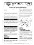
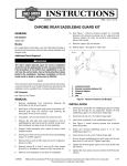
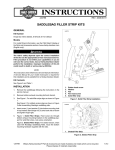
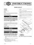
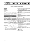
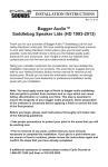
-J05068
REV. 2012-11-14
HERITAGE FLAT TOP AND LOCK KIT
GENERAL
is06603
Kit Number
1
90300010, 88373-10A
Models
For model fitment information, see the P&A Retail Catalog or
the Parts and Accessories section of www.harley-davidson.com
(English only).
Additional Parts Required
3M™ Scotch-Grip™ Plastic Adhesive 4693H, 5 ounce tube
Pop rivet gun
1. Backing board
Figure 1. Install Backing Board
The rider's safety depends upon the correct installation
of this kit. Use the appropriate service manual procedures.
If the procedure is not within your capabilities or you do
not have the correct tools, have a Harley-Davidson dealer
perform the installation. Improper installation of this kit
could result in death or serious injury. (00333a)
is06612a
1
Kit Contents
See Figure 6 and Table 1.
INSTALLATION
1.
Remove the saddlebags from the motorcycle.
2.
Lay saddlebag inner support board on lid up against lid
seam and trace marker line on leather. Adhesive is applied
to the area inside the marker line and to the support board.
1. Anti-rotation ring
NOTE
Textured side of the support board faces out.
3.
See Figure 1. Apply the adhesive. Ambient temperature
should be no lower than 65° F. (18° C). Flow an even coat
of adhesive to cover both saddlebag lid and the support
board and bond together while adhesive is tacky using
firm pressure. Allow one hour for the adhesive to set.
-J05068
Figure 2. Cut Hole for Lock Assembly
4.
Remove center chrome stud from saddlebag lid.
5.
See Figure 2. Locate the anti-rotation ring (the ring with
prongs) (1) on inside of lid opposite where chrome stud
was removed. Use a marker to draw a circle on the inside
of the anti-rotation ring where the lock will be installed.
6.
Use a hobby knife to cut out the marked circle.
7.
See Figure 6 and Table 1. Install flat washer (3) to lock
assembly (2).
8.
Insert lock assembly through the hole in the lid and install
anti-rotation ring (4), with prongs to the leather side, on
the inside of the lid.
9.
Install nut (5) over anti-rotation ring and tighten with 7/8
inch wrench or socket.
Many Harley-Davidson® Parts & Accessories are made of plastics and metals which can be recycled.
Please dispose of materials responsibly.
1 of 3
10. Install cam plate (6), T-bar (7) and screw (8). Tighten
screw to lock assembly. Use the key to work the lock
assembly to see if the cam is installed correctly.
is07460a
5
11. See Figure 3. Install saddlebag inner supports, left (1 )
and right (2). Use 5/16-18 temporary bolts (3), nuts (4)
and washers (5) (not provided in kit) to mount the frame
which will assist in the installation of the lock plate.
4
3
12. See Figure 5. Place lock plate (1) in a horizontal position
on outside of the saddlebag tub. Close the lid to center
the lock plate with the lock assembly (2) with T-bar (not
shown, under lid) in horizontal position and carefully lift lid
and mark location of lock plate.
13. Maintain position of lock plate and with a wood block inside
the saddlebag, drill 3/16 inch holes using the lock plate
as a template.
14. See Figure 6 and Table 1. Use a pop rivet gun and blind
rivets (9) and washers (11) to fasten lock plate to the
saddlebag tub. Washers will be placed on the inside of
the saddlebag tub over the head of the pop rivet.
15. Repeat steps for opposite saddlebag and install saddlebags to motorcycle.
16. If installing this kit with Detachable Saddlebag Conversion
Kit 90200641: Use hardware provided in that kit to attach
Flat Top inner brackets to saddlebag. Note: large washers
from Detachable Saddlebag kit should be discarded when
installing with Flat Top and Lock kit.
1
1.
2.
3.
4.
5.
2
Saddlebag inner support (left side, not shown)
Saddlebag inner support (right side)
Bolt (2)
Nut (2)
Flat washer (2)
Figure 4. Temporary frame installation with quick detach
saddlebag conversion kit (90200641)
is06530
2
is06529b
1
5
4
3
1.
2.
3.
4.
5.
1
2
1. Lock plate
2. Lock assembly
Figure 5. Positioning lock plate
Saddlebag inner support (left side, not shown)
Saddlebag inner support (right side)
Bolt (2)
Nut (2)
Flat washer (2)
Figure 3. Temporary frame installation without quick
detach saddlebag conversion kit (90200641)
-J05068
2 of 3
SERVICE PARTS
is06526a
A
1a
1a
9
11 10
6
8
B
5
4
3
7
2
1b
12 13
14
10
9 11
Figure 6. Service Parts: Heritage Bags Flat Top and Lock Kit
Table 1. Service Parts Table
Item
1a
Description (Quantity)
Lock assembly
Part Number
90300010
Lock assembly components
1b
•
Key (2)
71452-91A
2
•
Cam lock (2)
Not sold separately
3
•
Washer
Not sold separately
4
•
Anti-rotation ring
Not sold separately
5
•
Nut
Not sold separately
6
•
Cam plate
Not sold separately
7
•
T-bar
Not sold separately
8
•
Screw
Not sold separately
9
Rivet, blind (8)
Not sold separately
10
Lock plate (2)
90200063
11
Plain washer, Type A (8)
6717
12
Inner support, right side (not shown)
Not sold separately
13
Inner support, left side
Not sold separately
14
Inner saddlebag lid (2)
Not sold separately
Items mentioned in text, but not included in kit:
A
Saddlebag lid
B
Saddlebag tub
C
Detachable Saddlebag Conversion Kit
-J05068
3 of 3