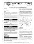
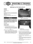
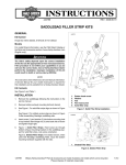
1
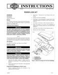
-J04656
REV. 2011-12-12
CHROME REAR SADDLEBAG GUARD KIT
49282-09B
10. See Figure 1. Remove antenna bracket (1), mounting
fasteners (2), antenna mounting nut (5), washer (4) and
antenna adapter (3). Save the antenna and hardware,
discard the bracket.
Models
11. Remove support (D) and discard.
For model fitment information, see the P&A Retail Catalog or
the Parts and Accessories section of www.harley-davidson.com
(English only).
12. Repeat Steps 1 through 9 for other side.
GENERAL
Kit Number
is05488
1
Additional Parts Required
3
The rider's safety depends upon the correct installation
of this kit. Use the appropriate service manual procedures.
If the procedure is not within your capabilities or you do
not have the correct tools, have a Harley-Davidson dealer
perform the installation. Improper installation of this kit
could result in death or serious injury. (00333a)
4
2
5
NOTE
This instruction sheet references service manual information.
A service manual for your model motorcycle is required for this
installation and is available from a Harley-Davidson dealer.
1.
2.
3.
4.
5.
Kit Contents
See Figure 3 and Table 1.
REMOVAL
Antenna bracket
Bracket mounting fastener (2)
Antenna adapter
Washer
Nut
Figure 1. Remove Antenna and Bracket
1.
Remove saddlebags from motorcycle following the
instructions in the service manual.
2.
See Figure 3. Remove grab strap screw and washer (G).
Remove grab strap (H). Remove seat following the
instructions in the service manual.
1.
See Figure 3. Install the rear saddlebag support mounting
screw (B) through the air suspension bracket (A) and
saddlebag support (7). Install screw finger-tight.
3.
If equipped, remove seat bumper (O) and screw (N).
2.
Install bolt (J) and nut (10). Tighten finger-tight.
4.
Remove left and right side covers (located in front of
saddlebags) by removing screw from bottom of side cover.
Save hardware and side covers for final assembly.
3.
Install stud receptacle (I) into saddlebag support (7).
4.
See Figure 2. Install antenna bracket with hardware
(removed earlier).
5.
Support muffler assembly with a block of wood or other
suitable method.
5.
Install new forward saddlebag guard (1 or 2) onto
saddlebag support (7).
6.
See Figure 3. Remove the screws (F) securing saddlebag
support to muffler supports.
6.
Install screw (4) and nut (3). Tighten finger-tight.
7.
7.
Remove bolt (J) and nut (M). Save bolt (J) for installation.
Discard nut (M).
Secure forward saddlebag guard with upper bolt (5) and
lower bolt (C) with nut (6). Tighten finger-tight.
8.
8.
Remove screws (B, K and C) and nut (E). Save screws
(B and C) for installation. Discard nut (E) and screw (K).
Tighten the forward guard upper screw (5) to 32-36 ft-lbs
(43-49 Nm).
9.
9.
Remove stud receptacle (I) and save for installation.
Tighten the lower screw (C) and nut (6) to 32-36 ft-lbs (4349 Nm).
-J04656
INSTALLATION
Many Harley-Davidson® Parts & Accessories are made of plastics and metals which can be recycled.
Please dispose of materials responsibly.
1 of 4
10. Tighten saddlebag support screw (4) and nut (3) to 70-100
in-lbs (8-11 Nm).
is05486
2
3
11. Tighten the rear saddlebag support mounting screw (B)
to 15-20 ft-lbs (20-27 Nm).
4
3
12. Tighten fender bracket screw (J) and nut (10) to 15-20 ftlbs (20-27 Nm).
1
13. Install muffler with screws (F) and remove wooden support.
Tighten screws to 96-144 in-lbs (10.8-16.3 Nm).
14. Repeat all steps for opposite side of vehicle.
7
15. Install seat and grab strap (H). Tighten grab strap screw
(G) to 12-15 ft-lbs (16.3-20.3 Nm).
16. Install left and right side covers with original hardware.
5
17. Install saddlebags with the original hardware following the
instructions in the service manual.
The front and/or rear guard(s) can provide limited leg and
cosmetic vehicle protection under unique circumstances.
(Fall over while stopped, very slow speed slide.) It is not
made or intended to provide protection from bodily injury
in a collision with another vehicle or any other object.
(00022a)
6
1.
2.
3.
4.
5.
Antenna base assembly
Antenna mast
Locknut (2)
Lockwasher
Antenna mounting bracket (purchased separately)
6. TORX screw (2)
7. Saddlebag rear support bracket
Figure 2. Antenna Mounting Bracket
-J04656
2 of 4
SERVICE PARTS
is07220
N
O
H
I
L
A
J
G
B
6
5
E
K
10
M
1
2
7
8
3
B
F
4
D
C
Figure 3. Service Parts: Saddlebag Guard Kit (Left Side Shown)
Table 1. Service Parts Table
Item
Description (Quantity)
Part Number
1
Forward guard, right
49176-09
2
Forward guard, left
49187-09
3
Locknut, 1/4-20
7686
4
Screw, 1/4-20
3601
5
Screw, TORX
4924
6
Locknut, 3/8-16
7601
7
Saddlebag support, left
49194-09
8
Saddlebag support, right
90781-09
9
Antenna bracket (not shown)
76516-09
10
Nut
7531
-J04656
3 of 4
Table 1. Service Parts Table
Item
Description (Quantity)
Part Number
Items mentioned in text, but not included in kit:
A
Air suspension mounting bracket
B
Rear saddlebag support mounting screw
C
Lower saddlebag guard screw
D
Saddlebag support
E
Lower saddlebag guard nut
F
Muffler screw (2)
G
Grab strap mounting hardware
H
Grab strap
I
Stud receptacle
J
Stock screw
K
Stock screw
L
Stock fender bracket
M
Nut
N
Screw (2)
O
Seat bumper (2)
-J04656
4 of 4