1
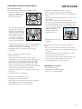
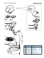
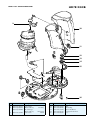
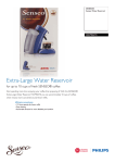
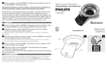
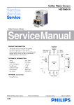
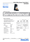
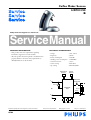
Coffee Maker Senseo
HD7812/50
/B
Philips Domestic Appliances and Personal Care
Service Manual
PRODUCT INFORMATION
TECHNICAL INFORMATION
- This product meets the requirements regarding
interference suppression on radio and TV.
- After the product has been repaired, it should function
properly and has to meet the safety requirements as
officially laid down at this moment.
-
Voltage
Frequency
Power consumption
Standby power consumption
Contents reservoir
Colour setting
Sap coding
Waterlevel
Sensor
:
:
:
:
:
:
:
220 - 230 V
50 Hz
1450 W
0.002 kWh
755 cc
Rich Silver
HD7812/50/B
Temp.
Sensor
Automatic
thermostat
L
Pump M
CONTROL
PCB
Boiler
Fuse
N
Push buttons
Published by Philips Domestic Appliances and Personal Care
05/09
Printed in the Netherlands
© Copyright reserved
Subject to modification
DISASSEMBLY- AND RE-ASSEMBLY ADVISE
Disassembly information
To remove the brew chamber lid cover handle as follows:
- Place the screwdriver on the
positions (see picture 1) and
lift the cover over the snap
locks on both positions.
picture 1
- The cover lid can now be lifted
up a little and to remove the
complete cover including lever
and push rod squeeze strongly
with two fingers both legs of
the push rod (see picture 2)
to each other, so that the two
pins will get out of the hinge
position on the brew chamber.
picture 2
- To remove lever from lid cover, take a screwdriver and bend
carefully the two lips/ribs in the lid cover outwards and
push the lever with force out of the hinge.
- Reassemble follow steps backwards, without using a
screwdriver.
To remove the back cover handle as follows:
- Remove valve outlet.
- Start at the upper side of the back cover and stick a
screwdriver into the 2 snap locks positions and gently pull
the back cover from the appliance so that a little chink
between back cover and brew chamber becomes visible.
- Put the screwdriver in to the 4 rectangular holes (snap
locks) at the back and gently pull the screwdriver such away
that the lips of the snap locks are bent outwards.
- If all clicks positions are loose, it is possible to remove the
back cover.
- Reassemble follow steps backwards.
HD7812/50/B
Removing Brew chamber head handle as follows:
- Back cover and 3-way valve must be disassembled!
- Place the appliance such a way that you are looking at the
boiler.
- First remove the boiler from the snap lock position of the
brew chamber.
(there were the boiler is fixed to the brew chamber)
- To do so use a screwdriver and bend slightly the both ribs to
the outer side and pull the boiler out of the fixation point.
- To remove the brew chamber, use your both thumbs (see
picture 3) and push strongly
with a little distortion
(rotation) until the brew
chamber comes loose.
- Reassemble follow above steps
backwards.
picture 3
To reach the components placed on the base handle as
follows:
- First remove back cover, brew chamber and 3-way valve.
- Remove both Torx T15 screws see exploded view in the near
of position A.
- Bend the 2 click snap locks with a screwdriver (see base),
and the housing can now be removed.
- To remove the rest of the housing unlock the last 4 snap
locks at the base and gently pull of the front cover.
- To reassemble follow above steps backwards.
OPTIONAL (accessories)
- XL watertank (10 Cups)
Commercial type number HD7982
Service code : 4222 259 20100
Removing 3-way valve handle as follows:
- Unsnap boiler out of brew chamber.
- Rotate the 3-way valve a quarter (90°) counter clockwise.
- Gently pull the 3-way valve out of the boiler.
- Reassemble follow the above steps backwards.
2-5
REPAIR INSTRUCTION
HD7812/50/B
Descaling
Regular descaling will prolong the life of your appliance and
will guarantee optimal brewing results for a long time.
• Follow the steps in the section headed “Preparing the
appliance for use” see DFU (Direction for Use manual)
• Instead of only water use a mix of water and Lemon sour.
• For the best result leave the mix of water and Lemon sour
for about 30 minutes in the appliance, before you start with
flushing the appliance.
• To get the best results repeat above-mentioned step once or
twice.
• When finished, flush the appliance twice by repeating the
above-mentioned steps only use water instead.
Volume adjustment
The new PCB circuit board makes it possible to adjust the
volume output by means of pushing the one-cup and two-cup
user controls.
How to adjust the volume output:
1. Be sure the boiler is filled properly, other wise perform fill
procedure see DFU for instructions.
2. Switch appliance on and wait until the unit is ready to
brew.
3. Be sure a pod holder is placed, but without a Coffee
POD. (Only adjusting with plain water)
4. Place a cup on the drip tray cover and push the one-cup
button.
5. When the appliance has finished it is stabilized to perform
the volume adjustment.
6. Empty the cup and push again for one cup setting,
measure the volume output with a graduated beaker.
In the table you can find the requirements for the
minimum / maximum volume output cc/mL values
depending from the country version:
One-cup setting, Including Pod holder, water spec.
(Without Coffee pod)
Min. water cc/mL
Max. water cc/mL
France version
104
120
General version
127
143
7. Unplug the appliance from the mains.
8. Press the 1- and 2 cup button simultaneously and plug the
mains on.
9. When above step succeeded the led will turn on
continuously.
10. Depending if the volume has to de- or increase you have
to push the 1- or 2 cup button.
Every time you push the 1- or 2 cup button the LED
will turn off for 0.5 second (feedback to user) and the
pump time will be shorten or lengthen for 0.5 seconds
depending which button was pushed.
Pushing 1 cup button pump, time will be shorten with
0.5 sec is approximately − 3.5 cc/mL (less coffee)
Pushing 2 cup button pump, time will be lengthen with
0.5 sec is approximately + 3.5 cc/mL (more coffee)
When the volume has to increase with 10 cc for example,
push the 2 cup button 3 times.
The new value will be stored when you switch the
appliance off by pushing the main switch. (LED will turn
off )
11. Turn appliance on again and brew one cup, measure the
volume. In case the volume is not within specification
repeat steps 6 - 11.
12. End.
Automatic filling procedure:
The Senseo PCB contains a new automatic filling procedure
software.
This filling procedure functions as follows:
First the consumer has to fill the water container and has to
plug the appliance on the mains.
When the Senseo main switch has been pushed and the
consumer pushes the one or two cup button, the Senseo will
start automatically the pump to fill the boiler.
When the boiler is filled the pump stops pumping.
When the filling procedure has been successful the software
will clear a Boiler_empty_flag in the EEPROM.
By means of this Boiler_empty_flag the system knows the
boiler is filled or not!
When the Senseo is switched off or disconnected from the
mains, the value of the Boiler_empty_flag is stored in the
EEPROM chip.
The old way of filling the Boiler by pushing the 1 and 2
cup button at the same time is still possible with this new
software.
Restoring the Boiler_empty_flag to production default:
Some times it is needed that the boiler of the Senseo have to
be emptied.
This for instance in wintertime were the possibility exists that
the boiler becomes frozen during transport e.g.
For those occasions it is handy to restore the Boiler_empty_
flag again to production default in the EEPROM.
Bringing the Senseo back into production status, has the
benefit the flush routine will be activated automatically
when installed by the consumer, see topic Automatic filling
procedure.
To SET the Boiler_empty_flag can be done by:
Keep the 1-cup button pressed while plugging in the power
cord of the appliance.
To check if the Boiler_empty_flag is really set, you should
reconnect the power cord a second time to the net (do not
push any buttons).
The LED should blink very fast for 0.5 seconds at the
moment the power cord was connected to the net.
3-5
PARTS LIST & EXPLODED VIEW
HD7812/50/B
1
2
3
7
4
8
5
6
Pos
Service code
1
2
3
4
5
6
7
8
4222 259 34690
4222 259 34740
4222 247 39540
4222 247 37140
4222 240 06670
4222 247 35790
4222 247 06810
4222 259 06890
Description
Pad holder single
Pad holder Double
Foam Chamber
Foam chamber cover
Drip Tray Cover
Drip Tray
Brew chamber radial seal
Distributor assy
Black
Black
Black
A
4-5
PARTS LIST & EXPLODED VIEW
HD7812/50/B
9
10
11
12
13
14
15
A
16
Pos
Service code
9
10
4222 259 15890
4222 259 06580
4222 259 20100
11
4222 247 37200
Description
Valve (3way)
Water tank assy
XL (10 Cups)
Water tank assy
Valve outlet
Soft Grey
Silent blue
Black
Pos
Service code
12
13
14
15
16
4222 247 35870
4222 247 05100
4222 247 39890
4222 247 05110
4213 247 05250
Description
Filter
WC Sealing
WC socket Hard
Corrugated tube/hose
Foot
5-5