1
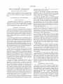
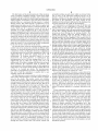
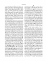
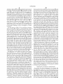
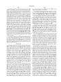
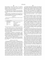
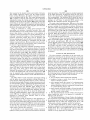
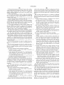
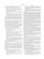
US005934904A
Ulllted States Patent [19]
[11] Patent Number:
Elrod et al.
[45]
[54]
DENTAL INSTRUMENT AND PROCESSES
Date of Patent:
3413277 10/1985
[75] Inventors: DeLynn Roy Elrod; Joseph Mark
Aug. 10, 1999
Germany ............................. .. 433/101
OTHER PUBLICATIONS
Forehand; Vernon Klm Kutsch> an of
.
5,934,904
Rosenberg, Stewart; Air Abrasion: The New Standard of
A1bany> Oreg'} Bryan G‘ M00re>
Care; Dentistry Today, Jul. 1996.
Carlsbad’ Cahf'
Kehoe, Bob; Assessing Air Abrasion; Dental Practice &
_
.
.
.
Finance; Mar./Apr. 1997.
[73] Asslgnee' Kreatlv’ Inc" San Dlego’ Cahf'
Reality Now; The Ratings: Air Abrasion Units, Updated
[21] Appl' NO‘: 08/975’438
Rosenberg, Stewart; Air—Abrasive Microdentistry—A New
[22]
Filed;
[60]
Related US. Application Data
Provisional application No. 60/062,406, Oct. 14, 1997.
Standard of Care; Focus.
Kreativ, Inc.; Mach 4.0 Air Abrasion Operator’s Manual,
Service Manual, Site Preparation Guide.
Kreativ, Inc.; Mach 4.1 Advertising Flyer, Sep. 1996.
[51]
Int. Cl? ..................................................... .. A61C 3/02
Rosenbergsl DDRT§A1Y Abrasion Takes Oi 1997
Commentary, Oct. 1996.
[52]
Nov_ 21, 1997
_
[58]
433/88; 433/27; 433/84
Primary Examiner—John J. Wilson
Fleld of Search .............................. .. 433/88, 101, 98,
Assistant Examiner_patrick A_ H?smier
433/80> 84> 27; 451/75> 78; 601/162
[56]
Attorney, Agent, or Firm—Lori M. Friedman
References Cited
[57]
U.S. PATENT DOCUMENTS
ABSTRACT
A dental instrument includes a handpiece having a noZZle
3,487,828 1/1970 Troy ...................................... .. 601/162
3 989 952 “A976 Hohmann
433/1O1
471147275 9/1978 Jones et
433/101
from Whlch 1S elected a Stream of abraswe pamcles’ and
valves operated under the control of a microprocessor WhlCh
regulate, as selected by a user, the stream of abrasive
4,446,456
4,635,897
433/101
______ __ 251/5
particles either as a continuous ?owing stream or a pulsed
?owing stream. The microprocessor enables the valves to be
433/101
operated at a plurality of different pulse durations. Aremote
- - - - -- 406/75
control unit, small enough to ?t into the palm of a hand of
4,676,750
4,708,534
4,733,503
5/1984 Beier _______ __
1/1987 Gallant ,,
6/1987 Mason
11/1987
3/1988 Gallant etaL
‘1V
5’
’
Gallant - - - - - - - - - -
'''
a user, provides control of the basic parameters of the
''''"
/
placed and allowing ?ngertip control of the instrument
433/88
without having to move away from the patient. The hand
5’636’983
6/1997 ShOJ-i et
433/88
piece is integrated with a main dental unit foot control for a
5,752,829
5/1998 Goldsmith et al. ..................... .. 433/88
8/1994
a am?”
instrument, allowing the instrument to be conveniently
4/1997 Abbott
,334,016
5 618 177
/
gnllleger
51/410
Goldsmith et al.
433/88
.
.
.
dental drill, so that the main Olenta1 unit foot Control Operates
both the dental drill and the handpiece.
FOREIGN PATENT DOCUMENTS
3243294
5/1984
Germany ............................. .. 433/101
54
64°
100° 1oo\
48 Claims, 11 Drawing Sheets
1
102T
(
.991o CHAMBER
mmgwlz
1001:
éQQESSURE
10%
SE CONTROL
illgbULl-l 104
10b
w
104A105
I
g
REGULATOR
107
1045
1050
10%
(107
EXHAUST
CH AMBER
CB
5,110
AIR
12
10c-1 6).,
11%
112
E111-A
MICROPROCESSOR
lNCLUDlNG
“1H3
EEPROM
'1 09b
112-1
113A
J——[_ 113B
|——*(
J
“SC
R
1180
125
_
f 24bf
PNEUMATICALLY
CONTROLLED
PRESSURE SWITCH
:
“1C
112-
N}
ELECTROMAGNETIC
1124)
PNEUMATIC CONTROL
0.0.
MODULE
24
A.C.
,
HAND PIECE
SAFETY SWITCH
117
U.S. Patent
Aug. 10,1999
Sheet 1 0f 11
5,934,904
U S. Patent
Aug. 10,1999
5,934,904
Sheet 3 0f 11
58
5o\
51
52°
Ttss
RE
->
SYgEI-JEQTED
'
-.
52
-_"./
AIR
PULSE
P
CONTROL
\
F. f
5A
PINCH VALVE
W
3A
’-~1-#‘-’~‘~'*
103
101
FIG. 3
102
H
. .
VIBRA?ON
PLATFORM
so
P
M K62
FIG. 3A
540
“A
I‘ -_O_- t: 155i
\“T I
52
5
54
ORIFICE PLATE
SECTION A— A
R
VIBRATOR
g
DPIECE
U.S. Patent
Aug. 10,1999
Sheet 5 0f 11
5,934,904
71‘
m2.
w
2
N
mo?
_.|/_.N
,
Wd
:
m
a?m:E/\ Q
am
F/\
_,
m
0 no
/miN/5 %
12
2.521
f@l
NM: \
.v
0E
U.S. Patent
Aug. 10,1999
Sheet 6 0f 11
5,934,904
FIG. 5
1160
FIG. 6
Z
U.S. Patent
mmm
Aug. 10,1999
Sheet 9 0f 11
5,934,904
U.S. Patent
Aug. 10,1999
Sheet 10 0f 11
5,934,904
0E
m
KPH
19
5,934,904
1
2
DENTAL INSTRUMENT AND PROCESSES
suriZed gas stream. The stream is used to perform various
RELATED PATENT APPLICATIONS
procedures under uniform pressure.
The use of high pressure in abrasive jet machining is
This is a utility patent application based on a United States
provisional patent application Ser. No. 60/062406, ?led,
Oct. 14, 1997, and entitled “Air Abrasion Dental Instru
ment.”
BACKGROUND OF THE INVENTION
10
of the instant invention is microprocessor controlled. The
entire operation of the unit of this invention is regulated by
the microprocessor. US. Pat. No. 5,618,177 to Abbott
Field of the Invention
The present invention is directed to a microprocessor
controlled dental instrument. More speci?cally, this instru
ment may be used in various dental treatments including
removing areas of decay from a tooth structure, preparing a
discloses an arrangement for feeding pressuriZed particulate
15
the suggested improvements.
These prior examples of pressure use in air abrasion
Background of the Invention
20
several years. Rosenberg, in the July, 1996 issue of Dentistry
abrasion including increased patient comfort, alleviation of
and dentists.
Air abrasion instruments have been available for use by
dentists for treating patients With an abrasive-laden ?uid for
many years. Such ?uids include abrasive-laden air directed
dentistry neither mention nor suggest the use of
microprocessor-controlled pulsed mechanism for improved
cutting ef?ciency and control of the instrument. Neither do
they mention or suggest other methods of increasing particle
speed besides the use of high pressure.
Today refers to air abrasion as the neW standard in dental
care. This article enumerates many advantages realiZed in air
patient anxiety, decreased use of anesthesia, increase of
dentists’ productivity, and decreased costs to both patients
material Which overcomes several draWbacks of earlier air
abrasion equipment. Microprocessor control is not one of
tooth for resurfacing, cleaning teeth, and the like.
The use of air abrasion in dentistry has been knoWn for
mentioned in U. S. Pat. No. 4,733,503 and US. Pat. No.
4,893,440 to Gallant et al. Disclosed herein is the use of high
pressure using abrasive-laden gas streams. Pressures of
several hundred psi up to 2,000 psi are disclosed.
US. Pat. No. 4,635,897 relates to a tube ?oW shut-off
device. This shut-off device is for a tube formed of ?exible
material and adapted to carry a ?uid. Control of ?uid ?oW
25
In an article in the March/April 1997 issue of Dental
Practice & Finance, Bob Kehoe authored an article entitled
“Assessing Air Abrasion”. This article, Which is intended to
provide advice on the use of air abrasion dentistry, states that
air abrasion is “designed to conservatively cut virgin teeth,
30
remove sealants and composite restoration, not amalgam or
other metals.” In light of this recent assessment, the results
onto the patient’s teeth for removal of decay, preparing the
of the applicant in removing amalgam With air abrasion
teeth to receive ?llings, prophylactic treatment, and so on.
Such abrasion instruments provide advantages over conven
techniques and the unit of the instant invention is a signi?
cant improvement.
tional dental drills. These include eliminating the heat, noise,
and vibration produced by conventional high-speed drills.
Also eliminated in many cases is the need for anesthesia as
Well as the need to cool the drill With ?uid.
There are, hoWever, issues of concern involved With the
use of air abrasion. One of the desired improvements in this
technology is to cut ef?ciently at moderate or loW air
pressures, While avoiding the use of potentially dangerous
high pressure. Higher pressure (ranging from about 100—160
psi) increases the cutting speed of the air abrasion dental
instrument, but this pressure level can be injurious for the
patient causing such injury as air emphysema. Rosenberg, in
the reference above, suggests using the loWest air pressure
possible. Reasons cited include patient comfort and better
control and visibility for the dentist.
Another disadvantage of using high pressures is that as
35
October, 1996 issue. In its ratings and updated commentary
on air abrasion units, it lists amalgam removal as a con
traindication for the use of air abrasive. Again, the results of
40
the applicants in removing amalgam With air abrasion tech
niques and the unit of the instant invention is quite surprising
and remarkable.
In another dental industry publication, DDRT (Dentists’
Desktop Reference to Technology), Rosenberg mentions
45
amalgam removal using air abrasion. He states that a super
sonic noZZle employed in the instrument Mach 4.0 manu
factured by Kreativ, Inc., the assignee of this invention, is
key to successful amalgam removal using air abrasion. This
50
the abrasive air ?uid exhausts from the air abrasion
instrument, an immediate drop in pressure occurs. This
pressure drop causes the ?uid to decrease in temperature.
The static temperature of the ?uid can decrease to, for
instance, about 20 degrees Fahrenheit. At this temperature,
Another publication doubting the possibility of amalgam
removal With air abrasion appears in Reality NOW in the
article not does mention the unique features of the air
abrasion unit of this invention, such as pulsing and micro
processor control thereof, and their importance to successful
amalgam removal.
SUMMARY OF THE INVENTION
55
This invention has several features, no single one of
air ?oW against a patient’s tooth can cause extreme discom
fort. In order to compensate for this, a heater may be needed.
Which is solely responsible for its desirable attributes. With
out limiting the scope of this invention as expressed by the
Another alternative to compensate for the coldness of the air
stream Would be to employ anesthetic, requiring the use of
a hypodermic needle. Patient discomfort, the need for
be discussed brie?y. After considering this discussion, and
particularly after reading the section entitled, “DETAILED
claims Which folloW, its more prominent features Will noW
60
anesthetics, and the use of needles are contrary to the use of
DESCRIPTION
OF
THE
PREFERRED
EMBODIMENTS,” one Will understand hoW the features of
air abrasion dentistry. Since the lessening of patient anxiety
and discomfort are basic tenets of air abrasion, these rem
edies for high pressure use are not acceptable.
In the past, various methods of feeding particulate abra
sive have been attempted. Gallant in US. Pat. No. 4,708,534
discusses the use of particulate abrasive material in a pres
this invention provide its bene?ts, Which include improved
65
patient care in that less time is required to conduct
procedures, in many cases Without anesthetic, and increased
versatility in controlling parameters of the particle laden
stream during treatment of a patient.
5,934,904
3
4
The ?rst feature of the dental instrument of this invention
is that it includes a handpiece having a noZZle from Which
is ejected a stream of abrasive particles, and a control valve
operated under the control of a main central microprocessor
Which regulates, as selected by a user, the stream of abrasive
optionally includes an audio alarm Which is activated When
one or more of the folloWing conditions prevail: an air
pressure selected by the user eXceeds the limits of the
instrument, an abrasive loading selected by the user exceeds
the limits of the instrument, the safety sWitch for the
handpiece for the instrument indicates that the handpiece has
not been lifted from the cradle for the handpiece.
particles either as a continuous ?owing stream or a pulsed
?oWing stream. The pulsed stream is produced by an air
supply system having an on-off valve Which is opened and
closed rapidly to bring the stream to a selected pressure. The
noZZle, Which may be a supersonic noZZle, is held in an
assembly at an angle ranging from 45° to 90°, and has a
10
diameter ranging betWeen 0.01 and 0.03 inch. Preferably, the
handpiece is integrated With a main dental unit foot control
enables gas pressure Within the miXing chamber to be
increased incrementally. The second valve is betWeen the
15
A collection canister may be provided into Which abrasive
particles in the handpiece are collected When the How of the
miXing chamber and the handpiece. This second valve is
operated at a ?rst operational mode that provides the pulsed
stream of particle laden gas or at a second operational mode
stream is discontinued. Preferably, the handpiece is operated
that provides the continuous stream of particle laden gas. A
under the control of a foot control pedal Which is depressed
by the user to turn on the How of the stream.
and a closed position, and in the open position it permits gas
to How into a miXing chamber and in the closed position
prevents gas from ?oWing into the miXing chamber. This
for a dental drill, so that the main dental unit foot control
selectively operates both the dental drill and the handpiece.
The instrument is a combination of some of the these and
other features. In one combination of features, ?rst and
second valves are used. The ?rst valve has an open position
pressure sensor detects the pressure of the gas Within the
20
miXing chamber and provides a control signal indicating the
The second feature is that the microprocessor enables the
control valve to be operated at a plurality of different pulse
pressure detected. The remote control unit enables the user
durations. To facilitate amalgam removal, the handpiece has
a supersonic noZZle, and the pulse duration, as adjusted by
chamber and (b) the operational mode. The microprocessor
the microprocessor, has an ON time ranging from 190 to 250
milliseconds and an OFF time ranging from 80 to 140
to select (a) the pressure of the gas Within the miXing
25
milliseconds. To facilitate precision control for cavity
preparation, the pulse duration, as adjusted by the
microprocessor, has an ON time ranging from 235 to 295
milliseconds and an OFF time ranging from 30 to 80
30
milliseconds. To facilitate cleaning, stain removal, and small
lesion treatment, the continuous mode is selected. The
stream pressure in the continuous mode for this application
ranges from 15 to 120 psi, and the abrasive particle ?oW rate
is from 2 to 3 grams per minute. The microprocessor
preferably is programmed to provide a self-diagnostic rou
pressure of the miXing chamber is increased incrementally
by selectively opening and closing the ?rst valve. The ?rst
operational mode is achieved by selectively opening and
closing the second valve to create the pulsed stream and the
second operational mode is achieved by maintaining the
35
tine and to hold the instrument at standby until a user
second valve continuously open to create the continuous
stream. The pulsed stream of the ?rst operational mode is at
different pulse durations as selected by a user.
In a second combination of features, a sensor detects the
manually actuates the instrument.
pressure of the stream of abrasive particles, and an air supply
system employs the on-off valve Which is opened and closed
The third feature is a remote control unit Which signals the
main central microprocessor to provide control of param
controls the operation of the ?rst valve to turn this ?rst valve
on and off until the gas pressure of the stream corresponds
to the gas pressure selected by the user actuating the remote
control unit. The remote control unit also enables the user to
select the concentration of particles in the gas steam. The
40
rapidly to bring the stream of abrasive particles to a selected
eters for the stream. This remote control unit includes
pressure. The microprocessor controls the operation of the
another microprocessor Which is coupled to the main central
microprocessor. Preferably, the remote control unit is small
on-off valve in response to the pressure detected by the
sensor to regulate the pressure of the stream of abrasive
particles. The remote control unit, operated manually by the
enough to ?t into the palm of a hand of the user. The use of
the remote control unit alloWs the larger and bulky compo
45
nents of the instrument to be housed in a central unit
remotely located from the patient. Nevertheless, the remote
control unit provides ?ngertip control of the instrument
Without having to move aWay from the patient. When not in
use, the handpiece is seated in a cradle on the remote control
unit having a safety sWitch Which is engaged by the hand
piece When seated in the cradle to enable the microprocessor
to recogniZe When the user is holding the handpiece. The
remote control unit includes a Warning system having indi
cators Which, in response to the self-diagnostic routine, alert
user.
In one embodiment of the invention, a system is provided
Which delivers to a plurality of different operatories, under
50
the control of a user in each individual operatory, separate
streams of abrasive particles provided by a remote miXing
chamber in Which abrasive particles are miXed With gas.
This miXing chamber is part of a central unit Which also
55
the user that one or more of the folloWing defective condi
tions prevail: a valve is defective, that the instrument needs
service, that the collection canister needs to be emptied, that
an adequate supply level of abrasive poWder is not available,
and that an operating system error eXists. The operating
system error may be inadequate available pressure, leaking
?uid supply lines, or the inability to reach or sustain desired
voltages for the instrument’s operation. A non-volatile read/
Write memory connected to the microprocessor retains the
last selected values of predetermined parameters of the
stream of abrasive particles as manually selected by the user
through the remote control unit. The remote control unit
user, signals the microprocessor to set the pressure of the
stream of abrasive particles to a pressure selected by the
contains the main central microprocessor. Each individual
operatory includes a handpiece from Which is ejected a
stream of abrasive particles. Each handpiece has a ?rst
operational mode that provides a pulsed stream of particle
laden gas and a second operational mode that provides a
continuous stream of particle laden gas. In each operatory is
60
a remote control unit Which each user uses to signal the main
central microprocessor to provide control of the parameters
for the stream being ejected from each handpiece in each
65
operatory. The remote control unit in each operatory is under
the common but separate control of the main central micro
processor Which alloWs each user at each individual opera
tory to select the operational mode of the handpiece at such
individual operatory.
5,934,904
6
5
FIG. 3C is a schematic diagram depicting the character of
a alternating current (A. C.) Which is recti?ed and applied to
This invention also includes a dental process Wherein a
pulsed stream of abrasive particles is directed at a tooth
structure. The pulsed stream is created by opening and
closing a valve operated by a microprocessor Which
the vibrator for the feeding abrasive poWder into the miXing
chamber.
FIG. 4 is schematic diagram of the manner in Which the
handpiece used in the instrument of the present invention is
integrated With a main dental unit foot control for a dental
drill.
FIG. 5 is a side elevational vieW of a handpiece using a
responds to command signals from a remote control unit
including a selector control Which enables a user to select
Wether the stream should be a pulsed or continuous stream.
Pulse duration may also be selected. The abrasive particles
are at a relatively high particle speed ranging from 110 to
160 meters per second and at an abrasive particle ?oW rate
ranging from 1 to 10 grams per minute. The stream is at a
10
handpiece shoWn in FIG. 5.
from the tooth structure, the stream is directed at the tooth
structure through a supersonic noZZle, With the stream being
in the form of pulses and the pressure of the stream eXceed
ing 40 psi and the abrasive particle ?oW rate ranging from
FIG. 7 is a schematic block diagram of the main central
15
1 to 10 grams per minute. To prepare a tooth structure for
veneer restoration, facing restoration, pit and ?ssure
sealants, partial or complete removal of composite
restorations, or repair of restoration failure sites, the stream
20
is directed as a pulsed stream at the tooth structure at a
pressure of from 40 to 80 psi and the abrasive particle ?oW
rate is up to 5 grams per minute. A supersonic noZZle may
be used. To prepare a tooth structure for etching metal,
porcelain, or composite restorations prior to repair, the
25
stream is directed at the tooth structure as a continuous,
non-pulsed stream at a pressure of less than about 80 psi,
30
35
ranging from 110 to 160 meters per second and at an
abrasive particle ?oW rate ranging from 1 to 10 grams per
minute. The stream is preferably at a pressure ranging from
15 to 120 psi. The diameter of the noZZle may be selected for
particular dental procedures including a 0.018 inch diameter
FIG. 9 is a block diagram of the individual remote control
units at separate operatories, With the individual remote
control units being control by a remote central control unit
of the program for the remote microprocessor housed in the
remote control unit.
DETAILED DESCRIPTION OF PREFERRED
EMBODIMENTS OF THE INVENTION
per minute. The abrasive particles are selected from the
group consisting of aluminum oxide, dolomite, and sodium
bicarbonate, and they are at a relatively high particle speed
microprocessor circuit used in the instrument of the present
invention.
FIG. 8 is a logic ?oW diagram depicting the main routines
of the program for the main central microprocessor used to
control the operation of the instrument of the present inven
tion.
FIG. 8A is a logic ?oW diagram depicting the sub-routines
routines of the program for the main central microprocessor
for controlling the audio alarm of the present invention.
including the main central microprocessor.
FIG. 10 is logic ?oW diagram depicting the main routines
preferably about 60—80 psi, and the abrasive particle ?oW
rate is up to 5 grams per minute. To clean a tooth structure,
the stream is directed at the tooth structure as a continuous,
non-pulsed stream at a pressure of from 20 to 40 psi and the
abrasive particle ?oW rate ranges from about 2 to 3 grams
supersonic noZZle.
FIG. 6 is a cross-sectional vieW of the noZZle end of the
pressure ranging from 15 to 120 psi. To remove amalgam
As schematically illustrated in FIGS. 1 through 6, the
major components of the dental instrument 1 of this inven
tion include an air pressure regulator 100, an abrasive
miXing chamber 102, a main central microprocessor 110, a
40
handpiece 116, Which sits in a cradle 115 of a remote control
unit 118. The remote control unit 118 includes a remote
microprocessor 123 for controlling the internal operations of
noZZle to remove large lesions and eXisting restorations, a
0.014 inch diameter noZZle for most small lesions, a 0.011
this unit. Both these microprocessors 110 and 123 are
inch diameter noZZle for very precise cutting, diagnosis of
programmed in accordance With conventional techniques
occlusal pits and ?ssures, incipient Class II and III lesions or
for placing ?ne retention in Class IV and V restorations.
45
DESCRIPTION OF THE DRAWING
The preferred embodiments of this invention, illustrating
all its features, Will noW be discussed in detail. These
embodiments depict the novel and non-obvious dental
instrument and process of this invention as shoWn in the
50
accompanying draWing, Which is for illustrative purposes
pressure of this stream at Which the dentist desires to
conduct the treatment of a tooth structure may be either
only. This draWing includes the folloWing ?gures (FIGS.),
With like numerals indicating like parts:
FIG. 1 is a schematic diagram illustrating the major
components of the preferred embodiment of the instrument
of the present invention.
increased or decreased, the loading of abrasive particles in
55
FIG. 2 is a diagram of the remote control unit of the
instrument of the present invention.
FIG. 3 is a side vieW, partially in cross section, of the
abrasive delivery system used in the dental instrument of
present invention.
FIG. 3A is a cross sectional vieW taken along line 3A—3A
of FIG. 3.
FIG. 3B is a schematic diagram depicting the manner in
Which the vibrator of the abrasive delivery system is actu
ated.
and the How diagram of the program for the main central
microprocessor 110 is shoWn in FIGS. 8 and 8A and the How
diagram of the program for remote control unit 118 is shoWn
in FIG. 10. Both these programs are discussed subsequently
in greater detail.
Using the remote control unit 118, a dentist adjusts the
parameters of an abrasive particle laden stream being ejected
from a noZZle 116a of the handpiece 116. Speci?cally, the
60
the stream may be either increased or decreased, the stream
may be either a continuous or pulsed stream, and the
duration of the pulses in the pulsed stream may be either
increased or decreased. The particle laden stream, either
continuous or pulsed, removes from the tooth being treated
undesirable dental material. This stream performs cutting,
abrading, deburring, peening, and polishing of tooth struc
tures. There is minimal disturbance of healthy enamel or
healthy dentin during removal of these undesirable materi
65
als.
The pressure of the particle laden stream may be varied
over a Wide range of pressure values ranging from a high
pressure corresponding to a maXimum inlet line pressure not
5,934,904
7
8
to exceed about 120 psi (pounds per square inch) to a loW
pressure of about 20 psi. The dentist may incrementally vary
central microprocessor 110 controls the pressure of the air
stream in response to both (a) the control signal from the
sensor 10 and (b) a control signal provided by the remote
control unit 118.
The remote control unit 118 includes all Warning indica
tors and parameter selection controls required to operate the
pressure one psi at a time Within this range. The pulsed
particle laden stream is at one of tWo different pulsed
conditions, namely, a PoWer PulseTM mode or a Micro
PulseTM mode. In the Continuous mode, a non-pulsed,
continuous particle laden stream exits the noZZle 116a of the
dental instrument 1 after the dentist actuates a main poWer
handpiece 116. In the pulsed mode, a pulsed particle laden
stream exits the noZZle end of the handpiece. The duration
of the pulse is longer in the PoWer PulseTM setting, typically
10
sWitch 24. The remote control unit 118 is small enough to ?t
into the palm of the hand of the dentist. As shoWn in FIG.
2, a control panel 22 of the remote control unit 118 serves
having an ON time ranging from 235 to 295 milliseconds
and an OFF time ranging from 30 to 80 milliseconds than in
as the user interface that alloWs the dentist to choose the
the Micro PulseTM setting, typically having an ON time
or she is conducting. It also alloWs the dentist While the
dental instrument is in operation to set the loading of
abrasive material in the stream (Beam Intensity) and to set
appropriate parameter settings for the desired procedure he
ranging from 190 to 250 milliseconds and an OFF time
ranging from 80 to 140 milliseconds. If, for example, the
15
dentist selects a pressure or particle loading Which exceeds
the pressure of the stream (Particle Energy). Without having
the limits of the instrument 1, an audio alarm, for example
a beeper 118a, is activated.
to move aWay from the patient, remote operation provides
the dentist With ?ngertip control of the variable parameters.
The dental instrument 1 is made ready for operation by
depressing the “Air” button 208. By depressing the “Mode”
button 212 on the panel 22, the dentist selects either a pulsed
or continuous stream. A number of lights 217, 218, and 219
Air under pressure from an air source, typically at about
80 psi (although higher or loWer pressure air may be used,
With a maximum of about 120 psi), is introduced through a
master valve 64 and tube 64a into an inlet 100a of an air
are illuminated to indicate the operational mode of the dental
instrument, and lights 207 and 209 are, respectively, illumi
air source is usually a compressor in the dentist’s of?ce or,
in the case of an alternate embodiment of the dental instru 25 nated to indicate if the dental instrument is in “on” or
“standby.” The “on” light 207 is illuminated When the foot
ment 1, the compressor is a component of the instrument
pressure regulator 100, including an “on/off” valve 99. The
pedal 68 is depressed, otherWise the “standby” light 209 is
itself. The “on/off” valve 99 in the regulator 100 is operated
by a solenoid 18 energiZed under the control of the main
central microprocessor 110 Which transmits a control signal
illuminated.
There are Warning indicators comprising a series of
over a line 20 to the solenoid. There is a sensor 10a in the
triangular lights 210, 211, 213, 214, and 216 along the
tube 64a betWeen the master valve 64 and the inlet 100a of
bottom of the panel 22 Which are illuminated under the
control of the main central microprocessor 110 under dif
the regulator 100 Which provides a control signal to the
central microprocessor 110 When the inlet pressure is inad
equate (typically less than about 20 psi) to operated the
instrument 1. An outlet 100b of the air pressure regulator
35
100 is connected through a tube 120 to a pressure sensor 10
Which detects the internal pressure of the dental instrument
1 and provides a control signal via a line 12 to the central
microprocessor 110. The outlet 100b of the air pressure
regulator 100 is also connected through a tube 101 to a
that a collection canister 109b needs to be emptied, the light
211 When lit indicates a loW level of abrasive poWder P in
the abrasive delivery system 50 (FIG. 3), and the light 210
When lit indicates a fatal operating system error such as, for
mixing chamber 102 of an abrasive delivery system 50
shoWn in FIGS. 3, 3A, and 3B through a branched tube 106
to a dump pinch valve 104-C of a pulse control module 104.
In the mixing chamber 102 abrasive poWder P (FIG. 3) is
mixed With the pressuriZed air from the regulator 100.
The pulse control module 104 regulates the pulse duration
When the dental instrument 1 is in the pulsed mode and
discontinues pulsing When in the continuous mode. It
includes, in addition to the dump pinch valve 104-C, an
abrasive pinch valve 104-A and a bleed pinch valve 104-B.
Under the control of the central microprocessor 110, via an
ferent problematic conditions. The light 216 When lit indi
cates that the abrasive pinch valve 104A has malfunctioned,
the light 215 When lit indicates that the dump pinch valve
104B has malfunctioned, the light 214 When lit indicates that
the instrument needs service, the light 213 When lit indicates
example, inadequate available pressure, leaking ?uid supply
45
lines, and the inability to reach or sustain desired voltages
for the instrument’s operation.
One self-monitoring safety feature of this invention is the
pinch valve failure circuit. The abrasive pinch valve 104A
and the bleed pinch valve 104-B are automatically moni
tored for operating failures by sensors 10b and 10c, respec
tively connected to these valves. If either one of these valves
104A or 104B develops a leak, the leaking pressure Will
cause an air pressure sWitch to close. These sWitches are the
sensors 10a and 10b and they are electrically connected to
the central microprocessor 110 over lines 10b-1 and 10c-1,
electromagnetic pneumatic control module 112, the pinch
valves 104A, 104B, and 104C are opened and closed. Each
of these valves 104A, 104B, and 104C has a piston-type
pinches to close the tube it engages. To open any one of these
respectively. The central microprocessor 110 Will sense the
closure and send a signal to the remote control unit 118,
Which Will then latch the appropriate pinch valve error light
pinch valves 104A, 104B, and 104C, the piston-type mecha
nism is exposed to atmospheric pressure (14.7 psi) and to
216 or 215. In order to reset the latched condition, the air
mode must be sWitched from “standby” to “on.”
mechanism (not shoWn) Which, in the closed position,
close any one of these pinch valves, the piston-type mecha
nism is exposed to the internal pressure of the dental
instrument 1, Which exceeds 20 psi When the dental instru
ment has been sWitched to “on” by depressing a button 208
on the remote control unit 118. As the pinch valve 104A is
opened and closed rapidly it creates a pulsed stream. Or, the
pinch valve 104A may simply be set in an open condition to
create the continuous stream. The pressure of each indi
vidual pulse typically ranges from about 20 to 120 psi. The
55
A LED (light emitting diode) seven-segment display 201
indicates abrasive particle loading in the stream (Beam
Intensity) and a LED seven-segment display 204 indicates
stream pressure (Particle Energy). The Beam Intensity may
be adjusted from 0 to 10 in increments of 1.0. The amount
of abrasive in the air stream may be adjusted upWard by
65
pushing a button 202 or doWnWard by pushing a button 203
to accommodate different particle loading according to the
needs and Wants of the dentist. The Particle Energy
5,934,904
9
10
adjustment, buttons 205 and 206, controls the air pressure of
the stream. When the air sWitch 208 is depressed to sWitch
to “standby,” and the handpiece 116 is removed from the
cradle 115 so that the safety sWitch 117 is disengaged, the
dental instrument is ready for use and is operated by
depressing the foot pedal 64 With actuates a pneumatically
shoWn seated in their cradles 2a so that a foot pedal 68 used
by the dentist for operation of these conventional handpieces
may also be used to operate the handpiece 116. The hand
piece 116 may be placed either in the empty cradle 2a‘ or the
cradle 115 on the remote control unit 118, Which is posi
tioned adjacent the roW of cradles 2a. When the foot pedal
68 is depressed, air is supplied through a conventional
controlled sWitch 121. The instrument 1 is thus sWitched to
“on.” An electrical foot sWitch 124 may also be provided as
operatory pneumatic system 4 supplying air under pressure
to all the dental handpieces, including the handpiece 116.
an optional feature. The digital display 204 shoWs the air
pressure setting selected by the dentist. Adjustments to the
dental instrument air pressure may be made by using the
“up” push button 205 or the “doWn” push button 206 to
The handpiece Which is lifted out of its cradle Will receive
air. The dentist has the option of placing the handpiece 116
in the cradle 2a‘ or the cradle 115. The pneumatic pressure
sWitch 121 of the the dental instrument 1 is connected
either increase or decrease this pressure, except it cannot
exceed the air pressure at the inlet 100a. The dentist may
simply glance at the control panel 22, and manipulate the
15
various control buttons, to monitor and control the operation
of the dental instrument With no interruption of dental
through the tube 122 to the operatory pneumatic system 4.
When the foot pedal 68 is depressed, the pneumatic pressure
sWitch 121 closes the electrical connection that is sent to the
central microprocessor 110 through line 125 (FIG. 1). When
operations.
the central microprocessor 110 senses that the pressure
sWitch 121 has been depressed, a signal sent to the remote
control unit 118 through line 119 to determine if the hand
As best shoWn in FIGS. 3, 3A, and 3B, the abrasive
delivery system 50 comprises a container 52 With a lid 51
that may be removed to add abrasive particles to the interior
of the container. At the bottom of the container 52 is an
piece 116 is in its cradle 115. If the handpiece is in the cradle
115, a handpiece safety sWitch 117 Will be closed and the
ori?ce plate 54 With a holloW cylinder 56 extending upWard
central microprocessor 110 Will ignore the activity of the
from the center of the plate. There is an outlet 58 at the top
of the cylinder 56 and an inlet at the bottom of the cylinder
56 Which is in communication With the mixing chamber 102
sWitch 121. If the dentist is using the cradle 2a‘ for the
handpiece 116, the same result occurs. Similarly, if the
handpiece 116 is not in the cradle, either the cradle 2a‘ or the
25
Which is directly beloW the ori?ce plate 54. A vibration
cradle 115, foot pedal depression Will initiate How of the
abrasive stream. Preferably, the central microprocessor 110
is programmed so that the handpiece 116 Will only operate
platform 60 mounted on a vibrator 62 is rigidly attached to
the chamber 52. Air under pressure from tube 101 enters the
mixing chamber 102 and ?oWs upWard through the cylinder
if all the other conventional handpieces 2 are in their cradles
56 to pressuriZe the interior of the container 52 While the
vibrator shakes the platform 60 and attached container.
Simultaneously, air rushes past the the ori?ce plate 54 With
the abrasive poWder P passing through holes 54a in the
ori?ce plate to enter the stream of air exiting the mixing
chamber 102 through the tube 103. This abrasive delivery
system 50 relies primarily on gravity to feed particles into
the air stream ?oWing through the mixing chamber 102.
2a, and the other handpieces 2 Will only be operable if the
handpiece 116 is in the cradle 2a‘ or the cradle 115.
FIGS. 5 and 6 illustrate a supersonic noZZle 116a for the
handpiece 116. This noZZle 116a is disclosed in US. patent
35
application Ser. No. 08/821,976, ?led Mar. 13, 1997, and
entitled Supersonic Converging-Diverging NoZZle For Use
On Biological Organisms, Which is incorporated herein by
reference and made a part of this application and Which is
When the level of abrasive material in the container 52 is at
a loW level, a photoelectric eye type sensor 52a provides a
oWned by Kreativ, Inc., the assignee of the present applica
control signal to the main central microprocessor 110.
FIG. 3B shoWs a circuit 70 for the control of the vibrator
application, the noZZle 116a is connected to an outlet in a
head assembly 20, and it includes a passageWay 38 With a
drive 71 (FIG. 1). A. C. current is recti?ed using a diode 72
and resistor 73 connected in series. The recti?ed signal 77 is
depicted in FIG. 3C. An isolator 74 couples the recti?ed
signal to the central microprocessor 110. As depicted in FIG.
be oriented at several different angles F With respect to the
tion. As discussed in detail in this co-pending patent
converging-diverging internal shape. This noZZle 116a may
45
3C, a square Wave X at the output of the isolator 74 indicates
to the microprocessor 110 the timing of the Zero crossing of
the recti?ed A. C. signal. The microprocessor 110 forWards
to a thyristor sWitch 75, through an isolator 75a, a spike
timing signal 76 Which is delayed relative to the leading
edge of the square Wave X to regulate the vibrator drive 71.
The spike signal 76 turns on the thyristor sWitch 75. A. C.
current passes through the thyristor sWitch 75 to the coil (not
shoWn) of the vibrator 62 to vibrate the platform 60. The
axis Z of the head assembly 20. NoZZle angles F of 45°, 67°,
or 90° have been used successfully. As discussed in greater
detail in connection With the EXAMPLES, the diameter d of
the outlet end of the noZZle 116a typically ranges from about
0.01 inch to about 0.03 inch. For example, the diameter d
may be 0.018 inch diameter noZZle to remove large lesions
and existing restorations, a 0.014 inch diameter noZZle for
most small lesions, or a 0.011 inch diameter noZZle for very
precise cutting, diagnosis of occlusal pits and ?ssures,
55
incipient Class II and III lesions or for placing ?ne retention
in Class IV and V restorations.
recti?ed A.C. current may be modi?ed to either increase or
OPERATION OF DENTAL INSTRUMENT
decrease the amount of vibration, and therefore, regulate the
amount of abrasive poWder P being fed into the air stream
passing through the mixing chamber 102. If the spike timing
signal 76 is synchronous With the recti?ed A.C. current, all
the recti?ed A.C. current Q is applied to the vibrator 62. If
the spike timing signal 76 is delayed slightly, a partial
recti?ed A.C. current R is applied to the vibrator 62. If the
spike timing signal 76 is greatly delayed, a greatly truncated
recti?ed A.C. current S is applied to the vibrator 62.
As illustrated in FIG. 4, the control of the handpiece 116
is integrated With the control for conventional handpieces 2
65
To operate the dental instrument 1, the dentist ?rst
sWitches on the main poWer sWitch 24 and depresses the
button 208. This applies poWer to the central microprocessor
110 through a D. C poWer supply 24a. The dental instrument
1 is noW in “standby” and the light 209 is illuminated. The
last pressure selected by the dentist is displayed on the
display 204, and the last abrasive loading of the stream
selected by the dentist is displayed on the display 201. If the
dentist Wishes to make changes in either of these parameters,
he or she manipulates the suitable control buttons 202, 203,
5,934,904
11
12
205 and 206. Depressing the foot pedal 68 actuates the
switch 121 and illumination of the “standby” 209 is discon
tinued and the “on” light 207 is illuminated. Prior to
switching to “on,” the valves 104A, 104B and 104C are all
closed as determined by the central microprocessor 110
internal instrument pressure and (b) to energiZe the solenoid
112-2 Which opens its valve (not shoWn) to connect the tube
113B to ambient air pressure. This actuates the valve 104A,
closing it, and actuates the valve 104B, opening it, to place
the tube 107 in communication With a collection cannister
109b having at its inlet an exhaust chamber 109 connected
to the line 107. Since ambient pressure is loWer than the
instrument’s pressure, air and particulates in the tube 105 are
providing appropriate control signals over the lines 111-A,
111-B, and 111-C to the appropriate solenoids 112-1, 112-2,
and 112-3 in the electromagnetic pneumatic control module
112, so that the system pressure is applied to the valves
104A, 104B and 104C. Each solenoid 112-1, 112-2, and
112-3 controls a valve (not shoWn) respectively in the tubes
10
113A, 113B, and 113C. With any one of these solenoid
controlled valves open, the pressure in the tube it is con
nected to Will be at atmospheric pressure. When the solenoid
controlled pneumatic valves are closed, the tubes 113A,
mouth are draWn into the noZZle 116a. This back ?oW of air
15
113B, and 113C are at the internal pressure of the dental
instrument 1. The central microprocessor 110 in response to
the normal ?uctuations of internal system pressure caused
by the valve 104A opening and closing When in one of the
116. The valve 104C remains closed to maintain the instru
ment’s pressure at the pressure selected by the dentist.
If the dental instrument 1 is (1) shut doWn by the dentist
turning the poWer sWitch 24 “off,” or (2) the pressure of the
instrument is reduced by the dentist pushing the button 206,
both the valves 104B and 104C are opened. As discussed
above, the opening of valve 104B is controlled and functions
achieve and maintain the selected stream pressure as air
leaves the system each time the foot pedal 68 is depressed.
as before under these conditions. When the poWer sWitch 24
25
central microprocessor 110 then provides a control signal
over the line 111-C to the solenoid 112-3 that sWitches its
valve (not shoWn) to ambient pressure Which is applied
through the tube 113C to the valve 104C to open this valve.
Opening the valve 104C vents the instrument of pressuriZed
air Which escapes through the tubes 106,108 and 107 out the
exhaust chamber 109. The internal pressure of the dental
button 205 until the display 204 shoWs 100. As soon as the
dentist sWitches to “standby” by pressing the button 208, the
instrument 1 is noW at ambient pressure and must again be
35
energiZed by the program for the main central microproces
sor 110.
The dentist may noW operate the handpiece 116 lifted
from the cradle 115 by stepping on the foot pedal 68. As long
as the foot pedal 68 is held doWn, a stream of particle laden
air exits the noZZle 116a of the handpiece 116. If the dentist
has selected either the PoWer Pulse or Micro Pulse mode, the
is turned “off,” the central microprocessor 110 detects this
condition by a signal forWarded over the line 24b. The
pressure of 100 psi, he or she Will repeatedly depress the
central microprocessor 110, in response to the pressure
sensed by the sensor 10, energiZes the solenoid 18 in short
electrical bursts to open and close the “on/off” valve 99 of
the air regulator 100 rapidly until the internal system pres
sure of the dental instrument 1 is equal to 100 psi. If the
limits of the instrument ar exceeded, the beeper 118a is
through tubes 105 and 105a prevents undesired burping
(extraneous eruptions of abrasive ?uid) from the handpiece
pulsed modes, or remaining open in the continuous mode,
operates the “on/off” valve 99 in the air regulator 100 to
The dental instrument 1 is an open looped system and the
pressure of the system is not preset, but returns to ambient
air pressure each time the instrument is turned off. Thus,
When the dental instrument 1 is sWitch to “standby,” the
internal pressure of the system must be increased from
ambient pressure to the pressure selected by the dentist. If,
for example, the dentist Wishes to operate at a stream
draWn through the branched tube 105a and tube 107, into
and through the exhaust chamber 109, With any particles in
the air collecting in the canister 109b. Asensor 109a detects
the level of poWder in the canister 109b, and provides a
control signal to the central microprocessor 110 When the
canister needs to be dumped. No materials from the patient’s
45
stream Will be pulsed by the valve 104A opening and closing
at the selected pulse duration. If the dentist has selected the
Continuous mode, the valve 104A remains constantly open
and the stream is continuous as long as the foot pedal 68 is
depressed. The stream exits the valve 104A and ?oWs
through the tube 105 to the handpiece 116 and out the noZZle
116a. In the dental instrument 1, the dentist may selectively
pressuriZed upon starting the instrument.
When the pressure of the stream is reduced by depressing
the button 206, the valve 104C is opened. The sensor 10
detects that the internal pressure is above the pressure
selected by the dentist, and this provides a signal to the
central microprocessor 110 to open valve 104C as discussed
above. As air escapes from the instrument, the valve 104C
remains open until the instrument’s pressure equals that
selected by the dentist. When this selected reduced pressure
is reached, the valve 104C is closed by the central micro
processor 110 signalling the solenoid 112-3 to position its
internal valve (not shoWn) so that the pressure applied to the
valve 104C is the reduced internal pressure, thus closing this
valve 104C. The central microprocessor 110 then in
response to the normal ?uctuations of pressure caused by the
valve 104A opening and closing When in one of the pulsed
modes, or being opened constantly in the continuous mode,
operates the “on/off” valve 99 of the regulator 100 to
maintain the reduced stream pressure.
increase or decrease the stream pressure as desired, or sWitch
from pulsed to continuous and vice versa, as desired. The
internal pressure of the instrument 1 is sensed by the sensor
55
MICROPROCESSOR
The central microprocessor 110 provides digital control
10 and the central microprocessor 110 takes the necessary
signals as opposed to analog control signals and is pro
grammed in accordance With conventional programming
techniques With the routines to be preformed illustrated in
measures to accommodate the changes called for as dis
cussed subsequently.
When the dentist releases the foot pedal 68, the sWitch
FIGS. 8 and 8A. These routines Will be discussed in greater
121 changes states and this condition is sensed and a control
signal is forWarded to the central microprocessor 110 over
the line 125. Signals are then forWarded by the central
microprocessor 110 over the lines 111A and 111B to the
detail subsequently. The preferred microprocessor is manu
factured by Microchip Technology, Inc. and identi?ed as
PIC16C74A. One advantage in using the central micropro
electromagnetic pneumatic control module 112,
cessor 110 to control the instrument 1 is that it may be
65
readily replaced With another microprocessor for repair of
respectively, (a) to deenergiZe the solenoid 112-1 Which
the instrument or for even reprogramming the instrument to
closes its valve (not shoWn) to connect the tube 113A to
preform differently than the original program.
5,934,904
14
13
As illustrated in FIG. 7, the central microprocessor 110
sure of the instrument 1 and signals the valve 104C to open
if the pressure needs to be loWered.
The multiple functions of the control panel 22 are under
the control of the routine 504. Included among these are the
includes a bus 83 to Which are electrically connected the
major components of the microprocessor, including program
storage memory 80 having memory components such as a
PROM, EPROM, ROM, FLASH, etc. (not shoWn), data
abrasive loading and the stream pressure set by manipulation
of the buttons 202, 203, 205, and 206, the desired Mode set
by the button 212, and standby set by the button 209.
The routine 505 responds to the conditions detected by the
storage memory 81 including various registers, a program
counter 82, utility timers and counters 83, con?guration
registers 84, instruction decoder 85, arithmetic unit 86, serial
communication port 87, an analog to digital converter 88,
sensor 10 to open and close the valve 99 in the air pressure
and input-output circuits 89. There is an external crystal
regulator 100 to establish the pressure selected by the user
manipulating the buttons 205 and 206. If stream pressure
resonator 81a connected to an internal oscillator 82a Which
determines the rate of execution of instructions for the
program. The oscillator 82a further provides the time base
required by the utility timers and counters 83, serial com
munication port 87, and analog to digital converter 88. An
EEPROM 90, Which provides a non-volatile read-Write
memory, is connected betWeen the input-output circuits 89
(Particle Energy), abrasive loading (Beam Intensity), or
operating Modes (pulsed or continuous) have been changed
15
In accordance With the routine 507, the foot sWitch 124,
the pressure sensor 10, and the safety sWitch 117 on the
cradle 115 for the handpiece 116 are tested, and the buttons
and the remote microprocessor 123 in the remote control
unit 118. Intermediate settings are forWarded to the data
202, 203, 205, 206, 212, and 208 are released. If the
storage memory 81 When manipulating the buttons 202, 203,
operating conditions are valid and a demand for abrasive
205, and 206 to vary the abrasive loading and pressure of the
stream and these intermediate settings are eventually erased.
How 507 is made by depressing the foot pedal 68, the routine
508 starts abrasive ?oW through the routine 509. If operating
As the user manipulates the buttons 202, 203, 205, and 206,
the last setting is stored in the EEPROM 90, so that When the
instrument 1 is turned off and then turned on again, this last
25
to prepare conditions for stream ?oW. The How Will be either
continuous or pulsed according to the user’s selection of
control unit 118.
The remote microprocessor 123 is substantially similar to
parameters through the remote control unit 118. Routine 511
Will monitor and regulate pressure according to the user
settings in accordance With the routines 504 and 506. The
routine 512 monitors the instrument’s safety conditions. It
the main central microprocessor 110. The principal differ
ence is that it is physically smaller, since it does not include
the analog to digital converter 88. Therefore, it conveniently
?ts Within the compact remote unit 118. This microprocessor
Will exit to the error handler routine 517 in the event that the
123 is also manufactured by Microchip Technology, Inc. and
identi?ed as PIC16C62A.
35
The program routines for the main central microprocessor
110 are represented by the logic ?oW diagrams of FIGS. 8
and 8A. In the start-up routine 500, the central micropro
cessor 110 poWers up several registers (not shoWn) and
latches (not shoWn) Which are set to standard settings
Routine 513 opens and closes the valve 104A as deter
513 When the valve 104A is open. Routine 514 senses the
completion of the start-up routine 500, the program, in
accordance With the routine 501, con?gures input/output
45
50/60 HZ line frequency for the vibrator 62, enables the
signals from the remote control unit 118, and continually
updates the signals being provided if the user changes a
setting While operating the instrument 1. Thus, the user may
change, for example, the abrasive loading or stream pressure
using the the remote control unit 118, and the appropriate
changes Will be made to adjust for the neW settings. Routine
514 also detects failures of pinch valve 104A and 104B. If
the user does not depress the foot pedal 68 Within a prede
pressure sensor 10, and recalls the last setting of the remote
control unit 118 from the EEPROM 90. A diagnostic check
is also preformed to con?rm that the instrument 1 is set for
termined time, for example, 2 minutes, the instrument Will
be sWitched to “standby.” Routine 514 Will also check to
determine if air valve 99 is still on, the handpiece 116 has
been returned to cradle 115, and Will cause the “loW air”
operations, and if not, the triangular error light 210 is
illuminated. A message Will be shoWn on the display 204 to
indicate the type of error occurring.
To complete the start-up, the main central microprocessor
voltage supply is outside the desired range, excess pressure,
closure of the safety sWitch 117, a disconnect occurs
betWeen the central microprocessor 110 and the remote
control unit 118, or other problems.
mined by the user setting the parameters using the remote
control unit 118. The vibrator 62 is energiZed by this routine
determined by the microprocessor’s manufacturer. Upon
circuits 89 and timer circuits of the data storage memory 81
as needed to respond to the sensors 10, 10a, 10b, 10c, 52a,
and 109a, enables the remote control unit 118, checks the
conditions are not valid or the foot pedal is not depressed,
the idle state is continued.
The routine 510 calls upon the central microprocessor 110
setting Will be automatically programmed in the remote
PROGRAM
during the routine 505, the neW values are Written to the
EEPROM 90 in accordance With the routine 506.
message to light the displays 201 and 204, if necessary.
55
Routine 515 senses if the footsWitch 121 is activated.
110 enters a main loop to monitor idle conditions and
respond to the commands of the routine 502. In the routine
502, the signals from the remote control unit 118 are
Routines 511 through 515 are repeated about 2000 times per
second during the instrument’s operation. With the release of
received, the information to be displayed on the the displays
201 and 204 is forWarded to the remote control unit 118, and
the remote control unit 118 is sWitched to “standby” if the
The air pressure regulator 100 is controlled by the rou
tines 520, 521, 522, 523, and 524, and 525. The pressure as
monitored by the sensor 10 is compared to the desired
setting through the routines 520, 521 and 522. If the desired
the foot pedal 68, abrasive feeding is stopped by routine 516.
foot pedal is not engaged for several minutes, for example,
2 minutes. The pinch valve sensors 10b and 10c and poWder
pressure is reached, no action is taken by routine 523. As
these routines 520, 521, and 522 are repeated at a high rate
level sensors 52a and 109a are monitored in accordance
provides intermittent control signals. The central micropro
of speed, the valve 99 in the regulator 100, opening and
closing rapidly, remaining open for a duration ranging
cessor 110 through the sensor 10 detects the internal pres
betWeen 0.3 to 0.6 milliseconds, Will remain closed When the
With the routine 503 and the central microprocessor 110
65
5,934,904
15
16
desired pressure is reached as called for by routine 524. As
and identi?es the error condition as a number Which is
hoWever, and the beep has not yet been signaled in accor
dance With a test of the beeped-?ag in routine 566, then the
beeper 118a is beeped, and the beeped ?ag is set. This use
of the beeped-?ag prevents a continuous beep from being
heard if the user persists in operating at loW pressure.
Whether the beeper 118a is activated or not, the message
“Lo Air” is sent to the displays 201 and 204 in accordance
With instructions from the central microprocessor 110 Which
shoWn on the display 204 of the remote control unit 118. If
are forWarded to the remote microprocessor 123. The regu
called for by the routine 525, the abrasive delivery system 50
remains idle or resumes delivering abrasive particles in
accordance With the routines 510 through 515.
The error handler routine 517 shuts off all the valves 64,
99, 104A, 104B, and 104C through routine 518,
de-energiZes the vibrator 62, illuminates the error light 210,
the error is not a severe, the routine 519 exits to idle state. 10 lator valve pattern is again examined in accordance With
routine 568. If the regulator valve 99 is operating on and off,
For severe errors, poWer is discontinued to the instrument 1.
Severe errors include, for example, poWer supply
malfunction, the microprocessor timer cannot be set, the
pressure sensor 10 malfunctions, or the vibrator drive 71
malfunctions. Non-severe errors include, for example,
inability to recall settings from the EEPROM 90, accidental
disconnection from the main central microprocessor 110 of
15
the remote control unit 118, or the remote control unit 118
or one of the valves 104A—104C is leaking.
the beeped-?ag is cleared in accordance With routine 563. If
the regulator valve 99 remains off in accordance With routine
523, the pressure is compared to the setting in accordance
With routine 570. If the pressure is Within the pressure
setting in accordance With buttons 205 and 206, subroutine
525 ends and the ready state (routines 502—508) or stream
?oW state (routines 511—515) resumes. OtherWise the ready
or stream ?oW state of the instrument is determined in
accordance With routine 572. If in stream ?oW mode, then
The control of the audio alarm, beeper 118a, is achieved
through the sub-routines illustrated in FIG. 8A. Routine 504
includes the sub-routines 550, 552, and 554. The sub-routine
the regulator 100 has been passing more air than required by
the stream resulting in the excess Which transfers control to
the error handler 517, shuts off master air valve 64, and
issues an error message. If the instrument is in ready mode
550 determines if any one of the buttons 202, 203, 205, or
206 is being depressed by the user. If not, the buttons are in
the reset state and the program advances to the next routine 25 (no stream ?oWing) pressure is relieved by opening valve
104c in accordance With routine 574 for a ?xed period of
505. If yes, the program advances to the next sub-routine
100—500 milliseconds. If the valve 104c failed to relieve
552, Which determines if the user has selected a value Which
pressure, the pressure sensor 10 Will still have an excessive
exceeds the limits of the instrument. For example, if the
value as determined by routine 576, transferring control of
dentist depresses the buttons 205 or 206 so that the air
the program to the error handler 517, shutting off the master
pressure is outside the range of 20 to 120 psi, the sub-routine
air valve 64, and issuing an error message.
552 Would provide a signal to energiZe the beeper 118a and
illuminate the error light 210. The same Would be true if the
The program routines for the remote microprocessor are
button 202 Was used to set the particle loading above 10, the
maximum of 10 grams per minute. If not, the program
advances to the next sub-routine 554, Which alloWs the
settings of the air pressure to be changed either one unit at
represented by the logic ?oW diagram of FIG. 10, and they
are designed to signal the central microprocessor 110 in
35
Individual segments of the displays 201 and 204 and the
a time or in units of ?ve When one of the buttons is 205 and
triangular Warning lights 210, 211, 213, 214, 215 and 216 are
206 are held doWn by the user. Upon reaching the selected
setting, the sub-routine 554 advances to the routine 505.
Routine 507 includes the sub-routines 556, 558, and 560
illuminated in accordance With instructions from the pro
gram from the central microprocessor 110 Which are for
Warded to the remote microprocessor 123.
The program routines for the remote microprocessor are
for activating the beeper 118a When the safety sWitch 117
has not been released by lifting the handpiece 116 from its
cradle 115. If the sub-routine 556 indicates that the foot
pedal 68 has not been depressed, the program advances to
the routines 508 through 502. If yes, it advances to the
sub-routine 558 Which checks to determine if the air is
available and the air indicator light 207 is “on.” If no, the
program advances to the routines 508 through 502. If yes, it
represented by the logic ?oW diagram of FIG. 10. The
routine 600 con?gures output ports for the LED display
45
drivers (not shoWn), and input ports for safety sWitch 117
and the buttons 202, 203, 205, 206, 208, 212. The routine
600 further sets the timing functions (a) for serial commu
nication With the microprocessor 110, and (b) for the rate at
Which display digits are multiplexed and button states are
advances to the sub-routine 560, Which checks to see if the
handpiece 116 has been lifted from the cradle 115 to release
the safety sWitch 117. If not, the beeper 118a is activated and
the error light 210 illuminated. If yes, the program advances
to the routines 508 through 509.
Routine 525 consists of the sub-routines 562 through 576
for con?rming proper operation of the regulator 100 Warning
accordance With the operation of the handpiece safety sWitch
117 and push buttons 202, 203, 205, 206, 208, and 212.
sampled. In routine 600 all the LEDs are enabled and lit for
one second so that the user may observe that they are
functional. The beeper 118a is also brie?y activated so that
the user may observe that it is functional and that poWer has
been turned on.
55
The routine 602 compares the current state of the buttons
the user of loW pressure, and protecting the patient from
202, 203, 205, 206, 208, 212 to a previous state sampled
excessive pressure. If the user has selected a pressure using
several milliseconds earlier, preferably from about 10 to
buttons 205 and 206 higher than that Which is available at
the master valve 64 or Which Will pass through the air tubes,
the regulator routine 525 Will continue to energiZe the
regulator 100, so that its continuous operation is detected in
accordance With routine 562 a?er Which the air pressure
sensor 10 is compared to the desired setting in accordance
With routine 564. It may be that the supply pressure or tube
pressure is just adequate in Which case no error condition is 65
to occur, and a beeped-?ag is cleared in accordance With
routine 563. If the delivery pressure is indeed too low,
about 20 milliseconds. Likewise the current state of the
safety sWitch 117 is compared to a previous state sampled
several milliseconds earlier. If there is a change in the button
state, a predetermined numeric code identifying Which indi
vidual button has changed state and Whether the the button
is activated or deactivated. This information concerning the
state of the buttons is transmitted to the microprocessor 110.
The state of the sWitch 117b is similarly tested and its state
of activation is transmitted to the central microprocessor
110. Signals from the central microprocessor 110 are for