1
Return to CD-ROM Collection Menu
Kodak DryView 8100 LASER IMAGER
Service Manual, Rev. C
Revision History
Warnings and Cautions / Safety and Agency Compliance
Section 1 – Specifications
Section 2 – Installation
Section 3 – Adjustments
Section 4 – Disassembly/Reassembly
Section 5 – Tools/Preventive Maintenance/Cleaning
Section 6 – Theory of Operation
Section 7 – Troubleshooting
Section 8 – QuickSheets
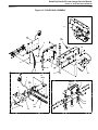
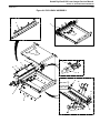
Section 9 – Illustrated Parts Breakdown
158-4010
96-0000-0211-1
Section 10 – Diagrams
Kodak DryView 8100 Laser Imager Service Manual
Revision History
2000 Rev. C
Revision History
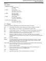
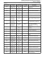
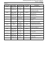
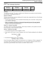
The original issue and revisions of this 8100 Service Manual are identified as follows:
Issue date (Rev. A): 10/99. Rev. B: 3/00. Rev. C: 11/00
All pages were dated October, 1999 in the Revision A issue. Subsequent changes have resulted in the
following Section by Section revision configuration:
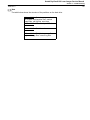
Section
Title/a
TOC
Rev.
–
Warnings –
Text
Rev.
C
Pages Changed in
Current Revision (C)*
Title and a pages
C
i, ii, iv
TOC
–
C
vi
1
A
C
1-2, -3
2
C
C
2-i, 2-ii, 2-1 thru -3, -6,
-7, -13 thru -26, -29
thru -46
3
A
C
3-5, -10
4
A
B
–
5
B
B
–
6
C
C
6-9, -10, -11,
7
C
C
7-i, 7-1, -22 thru -32,
-38, -39, -45 thru -54,
-62, -66
8
C
C
All pages
9
C
C
10
C
C
9-3, -7, -17 thru -19,
-23
All pages
* New and revised text is marked by a change
bar in the page margin. A mere change in text
location (e.g., rollover of unchanged text to the
next page caused by a text addition) is not
marked by a change bar. If all pages in a section
are revised or new, change bars are not used in
that section.
Kodak DryView 8100 Laser Imager Service Manual
Warnings and Cautions
2000 Rev. C
i
Warnings and Cautions
Read and understand all instructions before using.
!
WARNING
This equipment is operated with hazardous voltage which can shock, burn, or cause
death.
Remove wall plug before servicing equipment. Never pull on cord to remove from outlet. Grasp plug and
pull to disconnect.
Do not operate equipment with a damaged power cord.
Do not use an extension cord to power this equipment.
Use only the power cord supplied with this equipment.
Position the power cord so it will not be tripped over or pulled.
Connect this equipment to a grounded outlet.
Do not place a portable multiple socket outlet (power strip) on the floor. Mount the power strip on a wall or
on the underside of a table.
!
WARNING
For continued protection against fire, replace fuses only with fuses of the same type and fuse rating.
!
WARNING
This equipment contains moving parts that may be accessible to the user. Loose clothing, jewelry, or long
hair may cause minor personal injury or damage to the equipment. Do not operate equipment with the
covers open. Do not operate equipment with any of the safety interlocks overridden
!
WARNING
Not protected against ingress of liquids, including bodily fluids.
!
CAUTION
Do not use in the presence of flammable anesthetics, oxygen or nitrous oxide. This equipment dos not
have a gas sealed electronics enclosure and could ignite any flammable or explosive gases present in its
environment.
!
CAUTION
This equipment is intended to connect to other medical devices. Installation and service maintenance are
to be performed only by qualified service personnel. The laser in the equipment is not a patient device.
Therefore the equipment must be installed no closer than 1.83 meters from a patient bed or chair.
!
CAUTION
U.S. Federal law restricts this device to sale by or on the order of a licensed health care practitioner.
Kodak DryView 8100 Laser Imager Service Manual
Warnings and Cautions
2000 Rev. C
ii
Read and understand all instructions before using.
!
CAUTION
This equipment has been tested and found to comply with the limits for a Class B digital device, pursuant
to part 15 of the FCC rules. Those limits are designed to provide reasonable protection against harmful
interference in a residential installation. This equipment generates, uses, and can radiate radio frequency
energy and, if not installed and used in accordance with the instructions, may cause harmful interference
to radio communications. However, there is no guarantee that interference will not occur in a particular
installation. If this equipment does cause harmful interference to radio or television reception, which can
be determined by turning the equipment off and on, the user is encouraged to try to correct the
interference by one or more of the following measures:
• Reorient or relocate the receiving antenna.
• Increase the separation between the equipment and the receiver.
• Connect the equipment into an outlet on a circuit different from that to which the receiver is connected.
• Consult the dealer or an experienced radio/TV technician for help.
!
CAUTION
Do not substitute or modify any part of this equipment without approval of Eastman Kodak Company.
8100–38L
Kodak DryView 8100 Laser Imager Service Manual
Warnings and Cautions
2000 Rev. C
iii
Read and understand all instructions before using.
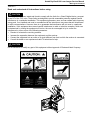
!
CAUTION
The equipment employs a 50 milliwatt laser. Laser radiation may be present when the machine operates
without the rear cover installed.
Use of controls or adjustments, or performance of procedures other than those specified herein, may
result in eye damage.
The rear cover shall be removed by authorized service personnel only.
CAUTION
Bypassing interlocks (other than the Service Interlock above)
will allow the system to run with the laser energized.
Exposure to the laser may result in permanent eye damage.
Class 1 Laser
Laser de catégorie 1
Laser-Klasse 1
Laser di Classe 1
Klass 1 Laser
! WARNING
Hazardous Voltage.
Can cause severe injury or death.
Disconnect power supply
before servicing machine.
! CAUTION
DISCONNECT AC POWER
BEFORE SERVICING
8100–39L
Note
General External Cleaning. This equipment may be cleaned with a damp cloth using water with
mild detergent, or commercial electronic equipment cleaner.
Kodak DryView 8100 Laser Imager Service Manual
Safety, Regulatory, EMC and CE Marking Compliance
2000 Rev. C
Safety, Regulatory, EMC and CE Marking Compliance
All safety, regulatory, EMC and CE marking information may be found in the User Guide for this device.
iv
Kodak DryView 8100 Laser Imager Service Manual
Section 1 – Specifications
2000 Rev. C
1-1
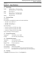
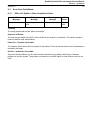
Section 1 – Specifications
1-1.
Dimensions
Height:
1168 mm (46 in.) – Top Cover closed
1581 mm (62-1/4 in.) – Top Cover open
Width:
635 mm (25 in.)
Depth:
660 mm (26 in.) – Front Door closed
1245 mm (49 in.) – Front Door open
Weight:
188 kg (414 lbs)
1-2.
Electrical Power
Input Voltage:
Line-matching is accomplished by jumpers on the power transformer.
•
100 VAC ± 10%, 50/60 Hz ± 3
•
120 VAC ± 10%. 60 Hz ± 3
•
230 VAC ± 10%, 50 Hz ± 3
Input Current Draw:
•
Less than 12 Amps at 100 VAC input voltage
•
Less than 10 Amps at 120 VAC input voltage
•
Less than 5.3 Amps at 230 VAC input voltage
Power Consumption: 700 watts maximum
1-3.
Storage Environment
Temperature:
–35° to 60°C (–31° to 140°F)
Humidity:
10% to 90% RH, Noncondensing
1-4.
Operating Environment
Temperature:
15° to 35°C (59° to 95°F)
Humidity:
15% to 85% RH, Noncondensing
Magnetic Field:
50 Gauss (maximum)
1-5.
Environmental Effects
Heat Dissipation:
3000 BTU/Hr (average)
Acoustical Noise:
Less than 55 dB at one meter (less than 70 dB momentarily)
Less than 80 dB, for non-repetitive tasks such as door open/close
1-6.
Film Size
The DryView 8100 will process 14 inch x 17 inch DryView Film.
Kodak DryView 8100 Laser Imager Service Manual
Section 1 – Specifications
2000 Rev. C
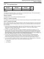
1-7.
Film Throughput
55 films per hour, assuming images of 1024 by 1024 pixels and a direct connect input
1-8.
Image Input Options
Note
The DryView 8100 can accept input from only one image source at a time: either digital or analog.
Digital Interface (standard):
•
3M Protocol Standard
•
One parallel RS-422 input
•
Copper input cable, up to 60 meters long
Video Interface (optional):
•
One RS-170 compatible input
•
Real-time frame grab
•
Interlaced or non-interlaced
•
Input for optional external clock
•
Copper input cable
DICOM Network Interface (optional):
•
Hardware – Input from customer’s DICOM network into the Kodak PACS Link 9410 Acquisition
System. Output from the 9410 is standard digital into the DryView 8100.
•
Interface Control – 3M 952 Host Protocol, to accommodate output from the PACS Link 9410
Acquisition system.
1-9.
Control Source Options
Host Control:
•
Use is dependent on modality source.
•
RS232 or RS422 connection directly to the imager.
•
Host can be located up to 60 meters (198 feet) from imager.
DryView V2 Keypad:
•
Available image formats include 1:1, 2:1, 4:1, 6:1, 9:1, 12:1, 15:1, 16:1 and 20:1.
•
Images can be acquired and stored in random or sequential order.
•
Can be located up to 3 meters (10 feet) from imager if connected directly.
•
Can be located up to 60 meters (198 feet) from imager if a UKEIB is used (copper cable only).
1-2
Kodak DryView 8100 Laser Imager Service Manual
Section 1 – Specifications
2000 Rev. C
1-3
1-10. Cables
•
DryView V2 keypad:
Not plenum rated
3 m (10 ft.)
•
UKEIB:
Plenum rated
3 m (10 ft.), 10 m (33 ft.)
30 m (98 ft.), 60 m (197 ft.)
•
RS232:
Not plenum rated
15 ft., 25 ft., 50 ft.
Host adapter cable
•
Digital:
Plenum rated
3 m (10 ft.), 10 m (33 ft.)
30 m (98 ft.), 60 m (197 ft.)
•
Analog (video): Plenum rated
3 m (10 ft.), 10 m (33 ft.)
30 m (98 ft.), 60 m (197 ft.)
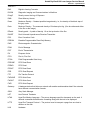
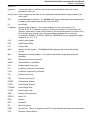
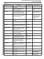
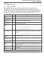
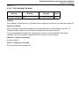
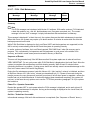
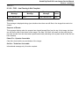
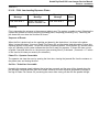
1-11. Glossary
Following are definitions of abbreviations and technical terms used in this manual.
ACK
Acknowledge – A hardware signal (response) that indicates reception of a signal.
A/D
Analog to Digital – The conversion of an analog signal to digital format.
ADC
Analog to Digital Converter – The hardware circuit that converts analog to digital format.
AIQC
Automatic image Quality Control – The subsystem in the laser imager consisting of
hardware and software that ensures consistent image quality.
API
Application Programming Interface – The Library and Tools software that handles
video parameters, and mediates differences between CHP file parameters and MIB video
variables.
BOM
Beginning of Message
Browser
A computer program that accesses and displays information from the web. It contains
multiple application programs, and uses an object’s name (URL) to determine which
application should be used to access the object.
Carrier Profile A term categorizing a subset of video parameters that describe the video signal itself as
opposed to the image content carried on the video signal.
CGI
Common Gateway Interface
CHP
Common Hardware Profile – A term describing a set of video file parameters as
implemented by the Video Board in the DryView 8100.
COM
Communications (Port)
CPU
Central Processing Unit – The microprocessing chip in a computer.
Kodak DryView 8100 Laser Imager Service Manual
Section 1 – Specifications
2000 Rev. C
1-4
DAC
Digital to Analog Converter
DICOM
Diagnostic Imaging and Communications in Medicine
DLogE
Density versus the Log of Exposure
DMA
Direct Memory Access
Dmax
Maximum Density – Greatest possible image density, i.e., the density of the black step of
the gray scale.
Dmin
Minimum Density – The measured density of film base plus fog. (Can be referenced either
to the film or the image.)
DPatch
Density patch – A patch of density 1.0 on the top border of the film.
DUART
Dual Universal Asynchronous Receiver/Transmitter
ECC
Error Correction Code
EPROM
Erasable Programmable Read-Only Memory
EMC
Electromagnetic Characteristics
EOM
End of Message
EOT
End of Transmission
EU
European Union
FIFO
First In, First Out
FPGA
Field Programmable Gate Array
FRDONE
FIFO Read Done
FREAD
FIFO Read
FRGNT
FIFO Read Grant
FRR
FIFO Read Request
FTP
File Transfer Protocol
FWDONE
FIFO Write Done
FWGNT
FIFO Write Grant
FWR
FIFO Write Request
Gateway
A hardware device that links one network with another and translates data if the networks
have different communication formats.
GSM
Gray Scale Manager
HPT
Host Protocol Translator
HTML
HyperText Markup Language – The source language used for documents on the web. It
embeds commands that determine formatting along with the text to be displayed.
HTTP
HyperText Transport Protocol – The protocol used to transport a page from one host to
another on the web.
H/W
Hardware
Kodak DryView 8100 Laser Imager Service Manual
Section 1 – Specifications
2000 Rev. C
Hypertext
1-5
A set of documents in which the documents contain embedded references to other
documents in their text.
Image Profile A term categorizing a subset of video parameters that describe the image content of the
video signal.
IMS
Image Management System – The DryView 8100 system that handles the acquisition and
formatting of the image before passing it on to the MCS.
I/O
Input/Output
IP Address
Internet Protocol Address – The numeric address of a site on the network, e.g.,
163.228.42.82. An IP address is actually a 32-bit binary number. For convenience, the
number is expressed in dotted decimal notation, which expresses each 8-bit section of the
32 bit number as a decimal value, and uses periods to separate the four sections.
For example: 10000001 00110100 00000110 00000000 (binary) is expressed in dotted
decimal as 129 . 52 . 6 . 0.
LCD
Liquid Crystal Display
LED
Light Emitting Diode
LUT
Lookup Table
MCS
Machine Control System – The DryView 8100 subsystem that controls the printing
process.
MIB
Management Information Base – The software that handles image processing and
formatting.
MPC
Maintenance Personal Computer
OMBC
Optics Module Control Board
PAL
Programmable Array Logic
PCI
Peripheral Component Interconnect
PCIO
Peripheral Component Input/Output
PLL
Phase-Locked Loop
PPP
Point-to Point-Protocol
PTADR
Pass-through Address
PTATN
Pass-through Attention
PTDONE
Pass-through Done
PTGNT
Pass-through Grant
RAM
Random Access Memory
RDFIFO
Read FIFO
REQ
Request
RET
Retransmit
RF
Radio Frequency
RSET
Register Set – The set of registers in the API Library software that stores video parameters.
RTD
Resistive Thermal Device
Kodak DryView 8100 Laser Imager Service Manual
Section 1 – Specifications
2000 Rev. C
1-6
RXD
The “receive” signal line, as defined by the RS232 and RS422 communication
specifications.
TFT
Transfer Function Table
TTL
Transistor to Transistor Logic
TXD
The “transmit” signal line, as defined by the RS232 and RS422 communication
specifications.
SIB
Serial Interface Board
SMPTE
Society of Motion Picture and Television Engineers
SOL
Start of Line
SOS
Start of Scan
SSR
Solid State Relay
STP
Shielded Twisted Pair
Subnet Mask A 32-bit value (in the format of an IP address) that specifies which bits of an IP address
specify the host. For example: 255.255.0.0 masks the network portion of the address
(255 = all 1’s). See IP Address for a description of address formats.
TCP/IP
Transmission Control Protocol/Internet Protocol
TPU
Time Processing Unit
UART
Universal Asynchronous Receiver Transmitter
UKEIB
Universal Keypad External Interface Box
URL
Uniform Resource Locator – A web address that locates a particular page on the web.
UTP
Unshielded Twisted Pair
WR
Write
WRFIFO
Write FIFO
WWW
World Wide Web
Kodak DryView 8100 Laser Imager Service Manual
Section 2 – Installation
2000 Rev. C
2-1
Section 2 – Installation
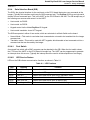
2-1.
Checklist of Installation Procedures
Following is a checklist of the procedures required during a typical DryView 8100 installation:
Unpacking and Initial Setup . . . . . . . . . . . . . . . . . . . . . . . . . . . . . . . . . . . . . . . . . . Paragraph 2-2
Connecting Cables . . . . . . . . . . . . . . . . . . . . . . . . . . . . . . . . . . . . . . . . . . . . . . . . . Paragraph 2-3
Setting Jumpers on the Video Board (as needed) . . . . . . . . . . . . . . . . . . . . . . . Paragraph 2-4
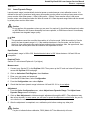
Configuring the System: . . . . . . . . . . . . . . . . . . . . . . . . . . . . . . . . . . . . . . . . . . . . . Paragraph 2-5
1. Assigning IP Addresses to the 8100 and Your Service PC . . . . . . . . . Paragraph 2-5-1
2. Connecting the Service PC and Accessing MPC . . . . . . . . . . . . . . . . . . Paragraph 2-5-2
3. Setting System Parameters . . . . . . . . . . . . . . . . . . . . . . . . . . . . . . . . . . . . Paragraph 2-5-3
4. Checking the Network (IP) Addresses . . . . . . . . . . . . . . . . . . . . . . . . . . . Paragraph 2-5-4
5. Setting Communications Parameters . . . . . . . . . . . . . . . . . . . . . . . . . . . . Paragraph 2-5-5
6. Setting Digital or Video Parameters . . . . . . . . . . . . . . . . . . . . . . . . . . . . . Paragraph 2-5-6 or 2-5-7
7. Setting up the Local Panel (language code, contrast and density) . . . Paragraph 2-5-8
8. Adjusting Image Quality (user ID, modality, aspect ratio,
match borders) . . . . . . . . . . . . . . . . . . . . . . . . . . . . . . . . . . . . . . . . . . . . . . . . Paragraph 2-5-9
___9. Validating Digital or Video Setup with the Customer . . . . . . . . . . . . . . . Paragraph 2-5-10
Entering Site Information (site address, contact, phone, etc.) . . . . . . . . . . . . . Paragraph 2-6
Editing the Service History Log . . . . . . . . . . . . . . . . . . . . . . . . . . . . . . . . . . . . . . . Paragraph 2-7
Backing up the Configuration Settings . . . . . . . . . . . . . . . . . . . . . . . . . . . . . . . . . Paragraph 2-8
Training Operators
Note
The installation procedures in this section cover three basic types of 8100 setup:
•
8100 directly connected to a digital host modality
•
8100 directly connected to a video host modality
•
8100 connected to a PACS Link 9410 or 9405 Acquisition System, which receives images from
a DICOM network. The PACS Link system sends the images to the 8100 in digital format.
Kodak DryView 8100 Laser Imager Service Manual
Section 2 – Installation
2000 Rev. C
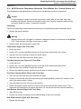
2-2.
2-2
Unpacking and Initial Setup
Note
Paragraph 2-2-1 can be performed by dock personnel or by a Kodak-trained technician. The
remainder of installation must be performed only by a Kodak-trained technician.
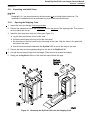
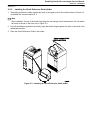
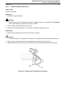
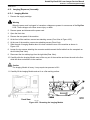
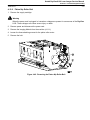
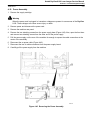
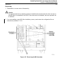
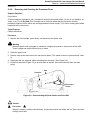
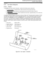
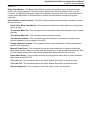
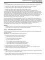
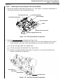
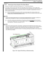
2-2-1.
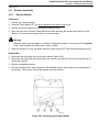
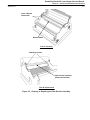
Opening the Shipping Crate
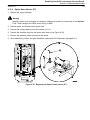
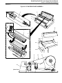
1. Inspect the crate for damage. Note any problems.
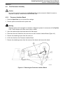
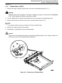
2. Remove the clamps that secure the front panel and the top panel of the shipping crate. Then remove
the front panel and the top.
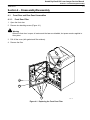
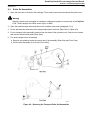
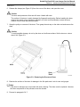
3. Install the front panel as a ramp, as follows (see Figure 2-1):
a. Lay the front panel down in front of the crate.
b. Unfold the small ramp at the top end of the front panel.
c. Set the bottom of the front panel on the front edge of the crate. Align the holes in the panel with
the holes in the crate.
d. Use the two bolts stored underneath the DryView 8100 to secure the ramp to the crate.
4. Remove the foam and corrugated packing from the top of the DryView 8100.
5. Cut and remove the poly bags from the imager. (Take care not to scratch the imager.)
6. Slowly pull the DryView 8100 out of the crate and ease it down the ramp.
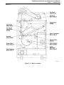
Figure 2-1. Removing the DryView 8100 from the Shipping Crate
Kodak DryView 8100 Laser Imager Service Manual
Section 2 – Installation
2000 Rev. C
2-3
7. Remove the filter from the crate.
8. Check that the document package shipped with the machine contains: (1) a User Guide, (2) a Quick
Reference Guide, (3) a Quick Reference Guide Holder, and (4) an Owner’s Kit.
9. Roll the DryView 8100 to the installation location. Position it for use, and adjust the feet so they
secure the machine in place.
Note
Failure to adjust and secure the feet can result in image artifacts on film if the machine is disturbed
during imaging.
!
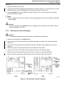
2-2-2.
!
Caution
To prevent damage to the DryView 8100, do not apply power and operate the machine until the
internal packaging is removed.
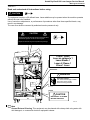
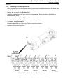
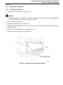
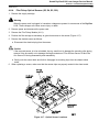
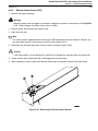
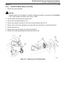
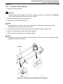
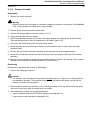
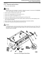
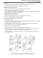
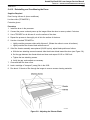
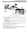
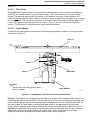
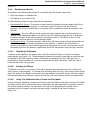
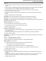
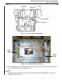
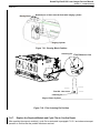
Removing the Internal Packaging
Caution
The following procedures must be performed by a Kodak-trained technician.
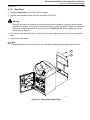
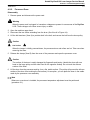
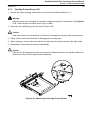
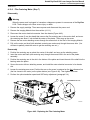
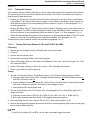
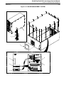
1. Remove the rear panel of the DryView 8100.
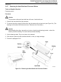
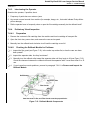
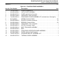
2. Remove the two PVC tubes from below the platen assembly (see Figure 2-2). Save the tubes for
future use.
3. Cut and remove the tag and the tie-wrap that holds the translation motor capstan away from the
flywheel.
4. Remove the tape and foam protecting the top and bottom of the flywheel.
5. Open the front door. Then unlatch and swing open the door to the exposure platen.
6. Remove the two screws securing the optics module to the front of the platen assembly.
7. Remove the silica gel moisture absorbent pack from the charcoal filter area. Discard it.
7 Remove
moisture
absorbent
pack.
Figure 2-2. Removing the Internal Packaging
Kodak DryView 8100 Laser Imager Service Manual
Section 2 – Installation
2000 Rev. C
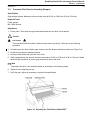
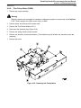
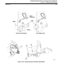
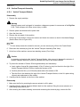
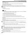
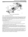
2-2-3.
2-4
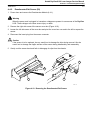
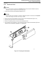
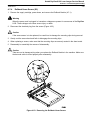
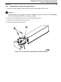
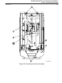
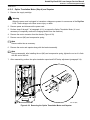
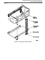
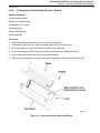
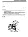
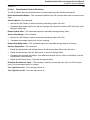
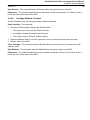
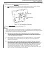
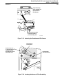
Installing the Quick Reference Guide Holder
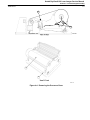
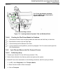
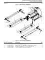
1. Temporarily position the holder against the back of the upper hood in the position shown in Figure 2-3,
to establish the correct location for it.
Note
After installation, the top of the holder (including the bent flange) should extend about 1/2 inch above
the hood, as shown in the front view in Figure 2-3.
2. Peel off the adhesive protection and firmly press the holder flanges against the back of the hood in the
established position.
3. Place the Quick Reference Guide in the holder.
Figure 2-3. Installing the Quick Reference Guide Holder
Kodak DryView 8100 Laser Imager Service Manual
Section 2 – Installation
2000 Rev. C
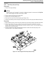
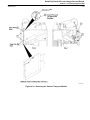
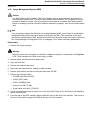
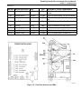
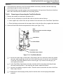
2-2-4.
2-5
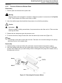
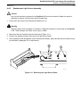
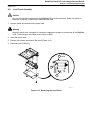
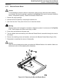
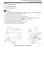
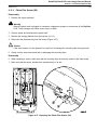
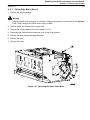
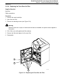
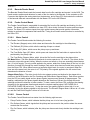
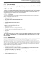
Preparing for Power Application
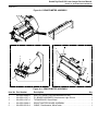
1. Check the wall power and set the power module jumper wires to match the measured wall power (see
Figure 2-4).
2. Replace the rear panel of the DryView 8100.
3. Install the charcoal filter in the lower right front of the machine. Refer to the decal on the filter for
installation instructions.
4. Connect the power cord to the DryView 8100 and to a power outlet.
5. Close the front door and the top hood.
6. Apply power to the DryView 8100.
7. Press the Open Door key on the Local Panel to open the front door.
8. Load film and close the front door.
Figure 2-4. Positioning the Line-Matching Jumpers
Kodak DryView 8100 Laser Imager Service Manual
Section 2 – Installation
2000 Rev. C
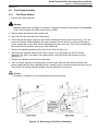
2-3.
2-6
Connecting Cables
Remove power from the machine before connecting any cables in the following procedures.
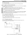
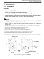
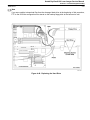
2-3-1.
Digital Source Directly to DryView 8100
If the DryView 8100 is to receive images from a digital modality, connect the cable between the DryView
8100 and the modality as shown in Figure 2-5.
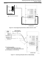
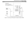
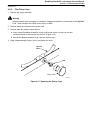
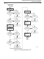
2-3-2.
DICOM Network through a PACS Link 9410 or 9405 to DryView 8100
If the DryView 8100 is to receive images from a DICOM network through a PACS Link 9410 or 9405,
connect the cable from the 8100 to the 9410 or 9405 as shown in Figure 2-6.
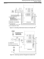
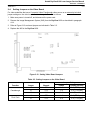
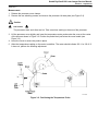
2-3-3.
Video Source Directly to DryView 8100
If the DryView 8100 is to receive images from a video modality, connect the cable between the DryView
8100 and the modality as shown in Figure 2-7. If the setup uses a 2-wire cable, refer to Table 2-1 for
connections. If the setup uses an octopus cable, refer to Table 2-2.
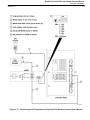
2-3-4.
Host Controller to DryView 8100
If the modality includes a host controller, connect it as shown in Figure 2-8. (For Siemens and other modalities
that require an HPT keypad, see paragraph 2-3-6.)
2-3-5.
DryView V2 Keypad to DryView 8100
If a DryView V2 keypad is to be used, refer to Figure 2-9 for cable connections.
2-3-6.
HPT Keypad to DryView 8100
For Siemens and other modalities that require an HPT(Host Protocol Translator) keypad, refer to
Figure 2-10 and Figure 2-11 for cable connections.
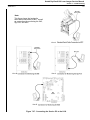
Figure 2-5. Connecting the DryView 8100 to a Digital Modality
Kodak DryView 8100 Laser Imager Service Manual
Section 2 – Installation
2000 Rev. C
2-7
50-Pin
Connector
COPCIL
Output
Board
PACS Link 9410 or
9405 Computer
1 Y cable (3 meters) 74-0500-5864-8
Image
Control
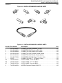
Figure 2-6. Connecting the DryView 8100 to a PACS Link 9410 or 9405
Figure 2-7. Connecting the DryView 8100 to a Video Modality
Kodak DryView 8100 Laser Imager Service Manual
Section 2 – Installation
2000 Rev. C
2-8
Table 2-1. Video Modality 2-Wire Cable Connections
Video Source
Video Board
API Channel
Video
Composite Video*
Sync
2-Wire Cable Connections
Video
In
Comp.
Sync
CA3
CA3
Green
Composite Video (Passthrough)*** CA3
CA3
Green
Composite Sync
CA3
CT3
Green
Red
Inverted Composite Sync
CA3
-CT3
Green
Red
Horiz.
Sync
Vert.
Sync
Video
Out
Pixel
Clk**
Red
Red
Note
* About 90% of video installations will use a composite video image source.
** The external pixel clock is optional. If it is not used, do not connect the cable. Use of the external
pixel clock requires resetting video board jumpers. See paragraph 2-4.
*** Composite video with passthrough requires resetting video board jumpers. See paragraph 2-4.
Table 2-2. Video Modality Octopus Cable Connections
Video Source
Video Board
API Channel
Video
Sync
Octopus Cable Connections
Video Comp.
In
Sync
Horiz.
Sync
Vert.
Sync
Video
Out
Pixel
Clk**
Composite Video*
CA3
CA3
A3
Composite Video (Passthrough)***
CA3
CA3
A3
T3
Composite Video Pixel
CA2
CA2
A2
T2
Composite Sync
CA3
CT3
A3
T3
Composite Sync Pixel
CA3
CT2
A3
T2
Inverted Composite Sync
CA3
-CT3
A3
T3
Inverted Composite Sync Pixel
CA3
-CT2
A3
T2
Separated Sync
CA3
SS
A3
T1
T2
T3
Separated Sync H Inverted
CA3
SS(-H) A3
T1
T2
T3
Separated Sync V Inverted
CA3
SS(-V) A3
T1
T2
T3
Separated Sync Both Inverted
CA3
-SS
T1
T2
T3
A3
T3
T3
T3
T3
Note
* About 90% of video installations will use a composite video image source.
** The external pixel clock is optional. If it is not used, do not connect the cable. Use of the external
pixel clock requires resetting video board jumpers. See paragraph 2-4.
*** Composite video with passthrough requires resetting video board jumpers. See paragraph 2-4.
Kodak DryView 8100 Laser Imager Service Manual
Section 2 – Installation
2000 Rev. C
2-9
Figure 2-8. Connecting a Host Control Console to the DryView 8100
Figure 2-9. Connecting a DryView V2 Keypad to the DryView 8100
Kodak DryView 8100 Laser Imager Service Manual
Section 2 – Installation
2000 Rev. C
Figure 2-10. Connecting an SHPT Keypad to the DryView 8100 (within 3 Meters)
2-10
Kodak DryView 8100 Laser Imager Service Manual
Section 2 – Installation
2000 Rev. C
2-11
Figure 2-11. Connecting an HPT Keypad to the DryView 8100 (Distance Greater than 3 Meters)
Kodak DryView 8100 Laser Imager Service Manual
Section 2 – Installation
2000 Rev. C
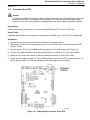
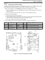
2-4.
2-12
Setting Jumpers on the Video Board
For video modalities that use a Composite Video Passthrough video source or an external pixel clock,
jumper settings on the video board must be changed. Proceed as follows:
1. Make sure power is turned off, and disconnect the power cord.
2. Remove the Image Management System (IMS) from the DryView 8100 as described in paragraph
4-14.
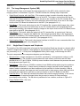
3. Refer to Figure 2-12 and reset jumpers as indicated in Table 2-3.
4. Replace the IMS in the DryView 8100.
Figure 2-12. Setting Video Board Jumpers
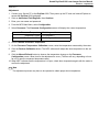
Table 2-3. Setting Jumpers on the Video Board
Jumper Setting
Function
Passthrough
Pixel Clock
Jumper
Channel
Enable
Disable (default)
J6
CT3
1–2
2–3 (TTL Sync)
J7
CT3
1–2
2–3 (TTL Sync)
J8
CA3
2–3
1–2 (Terminated)
J6
CT3
1–2
2–3 (TTL Sync)
J7
CT3
2–3
2–3 (TTL Sync)
Kodak DryView 8100 Laser Imager Service Manual
Section 2 – Installation
2000 Rev. C
2-5.
2-13
Configuring the System
Reconnect the power cord (if disconnected) and apply power to the DryView 8100. Then configure the
system as described in the following paragraphs. You will need the following information to configure the
system:
1. IP Address for the 8100 – See paragraph 2-5-1.
2. IP Address for your Service PC – See paragraph 2-5-1.
3. Your UserName (for entry into MPC) – Given to you during 8100 training.
4. Your password (for entry into MPC) – Given to you during 8100 training.
2-5-1.
Assigning IP Addresses to the 8100 and Your Service PC
For Direct-Connect 8100s: Both the DryView 8100 and the Service PC must be assigned IP addresses
so they can communicate with one another via MPC or for file transfer. If the 8100 is to connect directly
with a host modality, you can use the network address that was installed in the 8100 at the factory. The IP
Address of the Service PC must be set to the same subnet and network address as the IP address of the
DryView 8100. For example: If the IP address of the DryView 8100 is 149.98.202.xxx, the PC must be
set at 149.98.202.yyy.
For PACs Link/8100 Setups: The DryView 8100 cannot connect directly into the DICOM network. It
must be linked through a 9410 or 9405. Before the 9410/9405 is connected to the network it will be
assigned an IP address by the customer’s network administrator. Use this same basic address for both
the 8100 and the Service PC. As explained above, the first three octets of the address (from left to right)
must be identical, and the fourth octet must be different for all devices.
Use the 8100 Local Panel to assign IP addresses as described below.
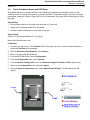
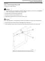
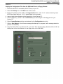
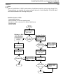
2-5-1-1.
Installing an IP Address
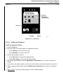
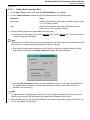
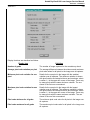
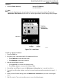
Use the following procedure at the Local Panel to install IP addresses (see Figure 2-13).
To display the location of the address you wish to change:
1. Press the Up Arrow, Test Print, and Backlight
keys simultaneously.
8100 Address
149.98.202.xxx
2. Press the Down Arrow key
8100 Netmask
255.255.255.000
3. Press the Down Arrow key.
8100 Gateway
0.0.0.0
4. Press the Down Arrow key.
Service PC Address
149.98.202.xxx
5. Press the Down Arrow key.
Service PC Netmask
255.255.255.000
6. Press the Down Arrow key.
Service PC Gateway
0.0.0.0
Note
Pressing the Up Arrow key at any display will return you to the previous display. Pressing the
Maintenance Information key will return you to the original display without saving editing changes.
Kodak DryView 8100 Laser Imager Service Manual
Section 2 – Installation
2000 Rev. C
2-14
Figure 2-13. Local Panel
2-5-1-2.
Editing an IP Address
To edit any displayed address:
1. Press the Enter key.
2. Move the cursor to the desired digit in the address as follows:
•
Press Calibrate to move the cursor right.
•
Press Backlight to move the cursor left.
3. Edit the selected digit as follows:
•
Press Up Arrow to increment the displayed digit.
•
Press Down Arrow to decrement the displayed digit.
4. After editing, press Enter (or press the Maintenance Information key if you wish to cancel the
editing).
5. If you wish to edit another address, scroll to the correct location and edit as described in steps 2–4.
6. When you have finished editing, press the Maintenance Information key to return to the original
menu.
7. Wait 2 minutes. Then cycle machine power to save all editing changes.
Kodak DryView 8100 Laser Imager Service Manual
Section 2 – Installation
2000 Rev. C
2-5-2.
2-15
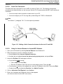
Connecting the Service PC and Accessing MPC
Your PC and the 8100 can be connected into a network environment in various ways so you can use
MPC. Three methods of network hookup are described in paragraph 2-5-2-1. (In addition, you can use a
direct serial connection, as instructed in paragraph 2-5-2-2.)
Note
For all connections, the IP Address of the PC must be set to the same subnet or network address as
that used by the 8100 (and 9410, if used). For example, if the IP Address of the 8100 is
149.98.202.xxx, the PC address must be 149.98.202.yyy, and the address of the 9410 (if a 9410 is
included in the system) should be 149.98.202.zzz.
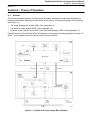
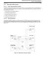
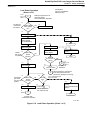
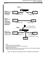
2-5-2-1.
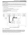
Network Type Connections
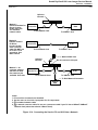
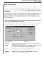
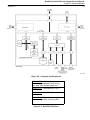
Method 1 for Direct Connect (8100 to Host) Setups
This method uses a network hub and two standard 10BaseT network cables. (See the top view in Figure
2-14.) This is the preferred method for direct connect setups.
1. Make sure power is applied to the hub.
2. Make sure that the Uplink or Cascade switch (if the hub is so equipped) is in the correct position.
Method 2 for Direct Connect (8100 to Host) Setups
This method connects the Service PC directly to the 8100 without use of a hub. (See the middle view in
Figure 2-14.) It has the disadvantage of requiring a 10BaseT crossover cable, which cannot be used for
FTP or TFTP operations.
Note
This method should not be used if your Service PC has a 10BaseT/100BaseT Network Card.
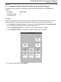
Method for Connecting into an 8100/ PACS Link to Network
This method (see Figure 2-14) requires a network hub and three standard network cables. Note that the
connection to the network wall jack from the hub must proceed from the Uplink (or Cascade) port of the
hub. (This connects all devices on the hub into the network.) The hub port adjacent to the Uplink port
cannot be used for connections to the PC or 8100.
1. Make sure power is applied to the hub.
2. Make sure that the Uplink or Cascade switch (if the hub is so equipped) is in the correct position.
Kodak DryView 8100 Laser Imager Service Manual
Section 2 – Installation
2000 Rev. C
2-16
Uplink or
Cascade
Hub
Method 1.
Preferred method for
Direct Connect
8100s. Uses hub
and standard
network cable.
Method 2.
Optional method
for Direct
Connect 8100s.
Uses crossover
cable. DO NOT use
for FTP or TFTP
operations. See
Note 4 below.
Service PC
1
To PC Network Card
Service PC
8100
1
To 10BaseT Jack
8100
2
To 10BaseT Jack
To PC Network Card
Network Wall Jack
Uplink or
Cascade
1
Do not connect to this port.
Hub
Method 3. On
customer network
with 9410 or 9405.
One network jack
available. Uses hub.
Service PC
1
1
8100
1
To PC Network Card
To 10BaseT Jack
To RJ45 Network Connector
9410 or
9405
Notes:
1. PC must have a network card installed.
2. Use the same ac circuit for input power for all components.
3. 1 = standard network cable.
4. 2 = network crossover cable. Do not use a crossover cable if your PC has a 10BaseT/100BaseT
Network Card (rather than a basic 10BaseT Card).
Figure 2-14. Connecting the Service PC and 8100 into a Network
Kodak DryView 8100 Laser Imager Service Manual
Section 2 – Installation
2000 Rev. C
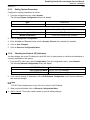
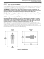
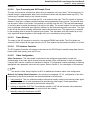
2-5-2-2.
2-17
Serial Port Connection
The direct serial port connection for use of MPC is shown in Figure 2-15. The following configuration
procedures are required before you can use your Service PC to communicate with MPC via the serial port
connection:
•
You must install a direct connection modem driver in your PC.
•
You must configure your PC for using dial-up networking with TCP/IP in Windows 95.
Note
See Section 7, paragraph 7-8-17, for the required procedures.
Figure 2-15. Making a Serial Connection between the Service PC and 8200
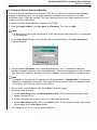
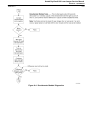
2-5-2-3.
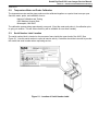
Using the Internet Browser to Access MPC Software
1. Open your web browser by selecting Internet Explorer from Windows 95.
2. Make sure the proxy server is disabled, as follows:
a. Select View and then Internet Options/Connection.
b. Uncheck the box labeled Access the Internet using a proxy server, and press Enter.
3. Access the DryView 8100 web page as follows:
a. If your browser is not running:
•
Click on Start and select Run.
•
Enter the IP address of the 8100 (do not include leading zeros). Then click OK.
b. If the browser is running: In the address box, enter the IP address of the 8100. Then press Enter.
c. Create a book mark by selecting Favorites, then Add to Favorites.
4. Click on Authorized Field Engineer, then Continue.
5. Enter your Username and Password in the box that appears.
(You can now select from the MPC main menu.)
Kodak DryView 8100 Laser Imager Service Manual
Section 2 – Installation
2000 Rev. C
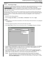
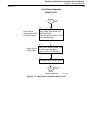
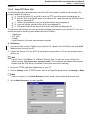
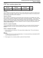
2-5-3.
2-18
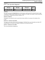
Setting System Parameters
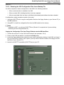
Configure the system parameters as follows:
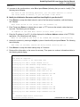
1. From the configuration menu, select System.
The following System Configuration screen will display:
Date
1999-xxx-xx
Time
x:xx:xx pm
Acquire Channel
Digital or Video (Select Digital for PACS Link setups)
Maximum Imageable Columns
4361 (Default)
Modem Initialization
AT&F1SO=1&H0&R1&W (Default)
2. Click on Edit System Configuration.
3. Enter the Date and Time and make sure the Acquire Channel entry matches the modality.
4. Click on Save Changes.
5. Click on Return to Configuration Menu.
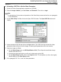
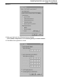
2-5-4.
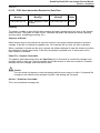
Checking the Network (IP) Addresses
You have already set up the IP Address for the 8100, but it is good practice to confirm that the address is
correctly established in the system.
1. From the MPC main menu, select Configuration. From the configuration menu, select Network.
The following Network Configuration screen will display:
8100 TCP/IP Address 163.228.48.82 (for example)
8100 TCP/IP Net Mask 255.255.252.0 (for example)
8100 TCP/IP Gateway 163.228.48.1 (for example)
2. If you need to change IP Addresses, click on Edit Network Configuration, enter the new addresses,
and save the changes.
Note
DO NOT enter leading zeros in any of the four octets in an IP Address.
3. When you have finished, click on Return to Configuration Menu.
4. Wait 2 minutes. Then cycle machine power to save all editing changes.
Kodak DryView 8100 Laser Imager Service Manual
Section 2 – Installation
2000 Rev. C
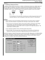
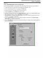
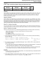
2-5-5.
2-19
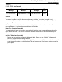
Setting Communications Parameters
Set up the parameters for command communication between the host and the imager (either via a
keypad or host console) as follows:
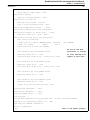
1. From the configuration menu, select Communications.
The following Communications Configuration screen will display:
Parity Even
Stop Bits 1
Data Bits 8
Baud Rate 1200 baud
EOM CR
Protocol 831/952
Memory Full Message BSY (MOV for PACS Link setups)
Alarm Mode Old
Acquire Timeout 25 seconds
P1 (PRI to DCR/PAS) 0 seconds
P2 (DCR to DCR/PAS) 0 seconds
P3 (STP to STC) 0 seconds
P4 (EXP to DCR/EOE) 0 seconds
P5 (EOE to PTC) 0 seconds
P6 (DCR to STC) 0 seconds
2. Click on Edit Communications Configuration.
3. Observe the following Caution and Note. Then enter the values required, and click on Save Changes.
!
Caution
Never change Parity, Stop Bits, Data Bits or Baud Rate while the system is actively communicating
with a host. This may cause a session or system hangup.
Note
With software release V1.0, the P2 value is used for both P2 and P1. The P3, P4, P5 and P6 values
can be changed, but they are not used by the software. The EOM value cannot be changed, It is
always CR.
4. Click on Return to Configuration Menu.
Kodak DryView 8100 Laser Imager Service Manual
Section 2 – Installation
2000 Rev. C
2-5-6.
2-20
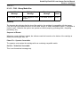
Setting Digital Parameters
If the system is to receive images from a digital modality:
1. From the Configuration menu, select Digital Setup.
The following Digital Configuration screen will display:
Pixel Depth
8 or 12 bit (depending on pixel width of modality)
Header Mode
Header/Line (for PACS Link setups, must match
9410/9405 setting)
Parity
None
2. Click on Edit Digital Configuration.
3. Enter the values required, and click on Save Changes.
4. Click on Return to Configuration Menu.
5. Skip paragraph 2-5-7 and proceed to paragraph 2-5-8, Setting up the Local Panel.
Kodak DryView 8100 Laser Imager Service Manual
Section 2 – Installation
2000 Rev. C
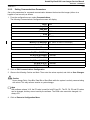
2-5-7.
2-21
Setting Video Parameters
If the system is to receive images from an analog modality, set the video parameters as described in the
following paragraphs.
2-5-7-1.
Checking the Version of Your Video Setup Software
The procedures require use of Video Setup software which is available on your Service Collection
CD–ROM, and stored on your Service PC. Before attempting video setup, make sure that the version of
this software is compatible with the 8100 IMS software (see Table 2-4).
Table 2-4. Video Setup/ System Software Compatibility
Video.exe Version
8100 IMS Software Version
1.0.2
1.0.3
1.1
1.1.2
1.2
2.0 or 2.1
1. If you are outside the video setup application, locate the Video Setup software on your Service PC as
follows:
•
Select c:\Program Files\ Kodak Health Imaging\DryView 8100 MPC Add-ons\ Video Setup\
video.exe
•
Right -click on video.exe, and select Properties, then the Version tab.
2. If you are inside the video setup application, click on the icon at the left of the title bar of the Video
Setup screen. Then select About Video.
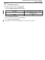
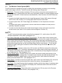
2-5-7-2.
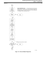
Video Setup–General
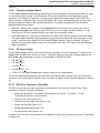
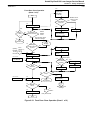
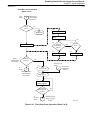
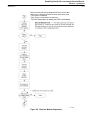
Video setup involves five basic steps:
1. Acquiring an image.––This involves importing an image and using a set of video parameters
sufficiently accurate to display the image. The preliminary video parameters can be set by any of three
methods:
•
Using AutoSync to automatically calculate the video parameter set (see paragraph 2-5-7-3).
•
Importing a qualified CHP parameter file (see paragraph 4 in Addendum A).
•
Manually entering a video parameter set (see paragraph 5 in Addendum A).
2. Setting the “Framing” Video Parameters––These include Horizontal Delay, Vertical Back Porch,
Horizontal Active, and Vertical Active (see paragraph 2-5-7-4).
3. Setting Horizontal Total (see paragraph 2-5-7-5).
4. Setting Pixel Delay (see paragraph 2-5-7-6).
5. Setting Black Level and Gain (see paragraph 2-5-7-7).
Note
See paragraph 6-2-3-7 in Theory of Operation for definitions of all video parameters.
Kodak DryView 8100 Laser Imager Service Manual
Section 2 – Installation
2000 Rev. C
2-5-7-3.
2-22
Acquiring an Image
Use AutoSync to acquire and set preliminary video parameter values as described below. You must have
a suitable test image for AutoSync. If you do not, you can use a clinical image if it has usable
characteristics. (See paragraph 2 in Addendum A of this section.) If your selected image does not have
suitable characteristics, the video parameters generated by AutoSync may be incorrect, and captured
image quality will be inferior.
Be aware that AutoSync does not work for all video formats, and it does not provide a final tuned set of
video parameters. If it does not work, you will have to load a preliminary set of video parameters either by
importing a CHP file or entering video parameters manually (see paragraphs 4 and 5, respectively, in
Addendum A).
1. Launch the Video Setup application.
2. Enter the Imager (IP) Address, your User Name, and Password. Then click on Login.
Note
For descriptions of the modes and operations of the Video Setup screen and tool bar, see paragraph
1 in Addendum A.
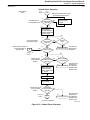
3. Connect the signal source that you will use for video setup to the 8100.
4. On the Video Setup Tool Bar, click on the AutoSync button. The AutoSync dialog box will display.
5. Use the dropdown Log Level box to select the level of the descriptive detail to display in the Results
window. The log levels include four categories: None (no information), Terse, Normal (this is the
default), and Verbose. Normal is the recommended setting.
6. Use the Pixel Delay Type box to select the method that AutoSync will use to determine the Pixel
Delay value.) For systems with software earlier than 2.0, the only option is Standard deviation. For
systems with 2.0 (or later) software, you can choose from among the following options:
Coarse – This method attempts to locate the pixel delay with the lowest pixel value standard
deviation, using a fast survey of candidate pixel delay values. It looks at only about one
sixth of the candidate values. but is a quick and useful method for a wide range of images.
(This is the default method.)
Kodak DryView 8100 Laser Imager Service Manual
Section 2 – Installation
2000 Rev. C
2-23
Refined Coarse – This is similar to the Coarse method, except it looks at all of the candidate pixel
delay values.
Histogram Peak Search – This method attempts to locate the pixel delay that yields the sharpest
histogram peaks, using a fast survey of the candidate pixel delay values. (It looks at about
one-sixth of the candidate pixel delay values.) This method has good results with image
patterns such as a resolve or vertical grill pattern.
Enhanced Peak Search – This method is similar to the Histogram Peak Search, except it looks at all
of the candidate pixel delay values.
Refined – This method is currently disabled.
Thorough – This method is currently disabled.
7. Click on Start. The AutoSync process will begin. (The process usually completes in less than a
minute, but can take much longer, depending on the image, the video format, and the options
selected. If AutoSync is successful, an image capture is executed and the image displays in the Video
Setup window. The Results window also displays a log of descriptive data.)
Note
If AutoSync is not successful, consider the following possibilities:
(1) Perhaps the image you are using is not suitable (see paragraph 2 in Addendum A). (2) Perhaps
there is a hardware problem (see paragraph 3 in Addendum A). If AutoSync will not work for you,
you can use a CHP file (if a suitable one is available) to load parameters, and then acquire an image
(see paragraph 4 in Addendum A). Or you can load parameters manually (see paragraph 5 in
Addendum A).
8. Click on Close.
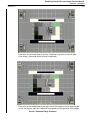
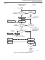
2-5-7-4.
Setting the Framing Parameters
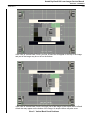
This procedure sets the image framing parameters: Horizontal Delay (or “Blanking Pulses”), Vertical Back
Porch (”Blanking Pulses”), Horizontal Active, and Vertical Active. Framing adjustments are required if
image data sampling does not correctly start and stop on the actual boundaries of the image. This shows
up in the image display either as extra lines of blanking data (usually shown as black) at the edge of the
image, or portions of the image clipped and not visible. View A in Addendum A shows the edge of the
image affected by each framing parameter. (It is easier to see rows and columns for framing if you zoom
the image to 400% or higher.)
1. On the Video Setup screen, make sure that Bit Depth Mode is set at 8 bit.
2. On the Video Setup Tool Bar, click on the Edit Video Parameters button.
3. In the Video Parameters window, use the dropdown Parameter box to select the following framing
parameters in order.
Kodak DryView 8100 Laser Imager Service Manual
Section 2 – Installation
2000 Rev. C
2-24
Parameter
Value
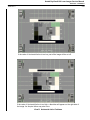
Horizontal Delay
Decreasing moves entire image to the right. Increasing moves
it to the left. (See View B in Addendum A).
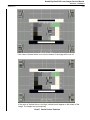
Vertical Back Porch
Decreasing moves entire image down. Increasing moves it
up. (See View C in Addendum A.)
Horizontal Active
Decreasing removes columns from right side of image.
Increasing adds columns. (See View D in Addendum A).
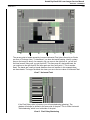
Vertical Active
Decreasing removes rows from bottom of image. Increasing
adds rows. (See View E in Addendum A).
4. To adjust a parameter value, use the dropdown Value box to enter the new value as follows:
a. Check the Automatically Acquire box.
b. Use Up Arrow or Down Arrow to enter small changes. (The changes will post automatically.)
c. Enter larger changes via the keyboard. Then press Enter to post the change.
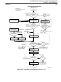
2-5-7-5.
Setting Horizontal Total
This parameter (sometimes referred to as “Clocks per Line” or “Pixels per Line”) can be adjusted to
remove vertical aliasing stripes (bands) from the image. (Ghosting on both the leading and trailing edges
of regions on the image is a symptom of incorrect Horizontal Total. See View F in Addendum A.)
1. On the Video Setup screen, make sure Bit Depth Mode is set at 8 bit.
2. Use the Video Parameters window to verify/adjust Horizontal Total.
3. To adjust a parameter value, use the dropdown Value box to enter the new value as follows:
a. Check the Automatically Acquire box.
b. Use Up Arrow or Down Arrow to enter small changes. (The changes will post automatically.)
c. Enter larger changes via the keyboard. Then press Enter to post the change.
2-5-7-6.
Setting Pixel Delay
This parameter can be adjusted to eliminate ghosting (shadowing), either by visual inspection or by
means of the Consistency Sweep and Check function included in the Video Setup software. See View G
in Addendum A for an illustration of shadowing caused by incorrect Pixel Delay.
1. On the Video Setup screen, set Bit Depth Mode to 10 bit.
2. Use the Video Parameters window to verify/adjust Pixel Delay, as necessary.
3. To adjust a parameter value, use the dropdown Value box to enter the new value as follows:
a. Check the Automatically Acquire box.
b. Use Up Arrow or Down Arrow to enter small changes. (The changes will post automatically.)
c. Enter larger changes via the keyboard. Then press Enter to post the change. See View )
4. To aid in fine-adjusting Pixel Delay, refer to Consistency Sweep and Check, paragraph 6 in Addendum
A.
Kodak DryView 8100 Laser Imager Service Manual
Section 2 – Installation
2000 Rev. C
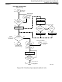
2-5-7-7.
2-25
Setting Black Level and Gain
1. On the Video Setup screen, make sure that Bit Depth Mode is set at 10 bit.
2. Use the Video Parameters window to adjust the parameters to the following values:
Parameter
Value
Black Level
Adjust so the minimum pixel value in the entire image is either
1 or 2 (see step 3 below).
Gain
Adjust so the maximum pixel value in the entire image is
either 1021 or 1022 (see step 3 below).
3. Use the following guidelines to adjust Black Level and Gain.
a. Select areas on the image that show the blackest black and the whitest white. Then use the zoom
function to enlarge these areas.
Note
When you zoom, make sure you keep your selected black and white areas in the viewable area, and
that there are no edge transition lines (blanking pulses) in the area.
b. Click on the Viewable Area Info button on the Tool Bar to display the following window. (At this
point both this window and the Video Parameters window should be displayed.
c. Use the Video Parameters window to change parameter values, as necessary, while observing
the Viewable Area information. (Increasing the parameter value will cause the pixel value to
decrease, and vice versa.)
Note
An optional mode of displaying pixel values is to use Info Mode (selectable from the tool bar) and
position the cursor over the black and white image areas to display the pixel value.
4. After final Gain has been set, verify that the Black Level minimum pixel value setting is still either 1 or
2. If not, reset Black Level and Gain.
Kodak DryView 8100 Laser Imager Service Manual
Section 2 – Installation
2000 Rev. C
2-5-7-8.
2-26
Confirming and Saving the Video Parameters
1. Acquire a final image and print it to film using the MPC Print facility. (Do NOT print an image using the
keypad or host control.) The print will be a 1-up image in replicate mode, which reproduces the image
exactly without any smoothing. Any blurring or ghosting will be evident, and not disguised by
processing of the image.
2. Inspect the print to confirm optimal image quality.
3. Use the Save CHP File function to store the set of video parameters in MPC.
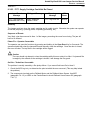
2-5-8.
Setting up the Local Panel
Set up the language code (English or Numeric) for the Local Panel, and set starting values for contrast
and density in the Local Panel as follows:
1. From the configuration menu, select Local Panel. The following Local Panel Configuration screen will
display:
Language Code English
Current Contrast 1
Current Density 3.000
2. Click on Edit Local Panel Configuration.
3. Enter the values required, and click on Save Changes.
4. Click on Return to Configuration Menu.
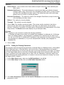
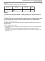
2-5-9.
Adjusting Image Quality
Set the basic image quality parameters as follows:
1. From the configuration menu, select Image Quality.
The following Image Quality Configuration screen will display:
User ID Enter ID (see step 3 below).
Modality Enter descriptive name for modality.
Aspect Ratio 1.00
Match Borders Option Enabled, usually, (but per customer preference)
Force TFT to Film Dmin Disabled, usually (but per customer preference)
Mag Scaling Disabled
Pixel Correct Off (See step 4 below.)
831 Cmd Set Beta Table – Sharp 3
831 Cmd Set Beta Table – Smooth 15
952 Beta Override Off
Prints until PM 9965 (See step 6 below.)
2. Click on Edit Image Quality Configuration.
Kodak DryView 8100 Laser Imager Service Manual
Section 2 – Installation
2000 Rev. C
2-27
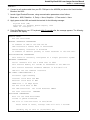
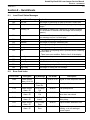
3. For the User ID entry, enter the ID information that the user wishes to appear on each sheet of film.
This ordinarily includes user name, date, and job data. Use the following codes to abbreviate entries:
Code
Indicates
%C
Enter a timestamp in the following format: DOW (day of week) MMM DD HH:MM:SS YYYY
%J
Enter job information in the following format: #J N:M (where J = system job number,
N = current copy, and M = total copies
%%
Enter a % character
Examples of User ID entries:
If you enter University Hospital: %C %J, the following will print:
University Hospital: Mon Jun 14 11:01:14 1999 #35 8:50
If you enter %C %J ––– University Hospital, the following will print:
Mon Jun 14 11:01:14 1999 #35 8:50 ––– University Hospital
If you enter University Hospital Radiology at 90%% Capacity, the following will print:
University Hospital Radiology at 90% capacity
Note
Unrecognized codes will print out as is. For example, if you enter %D, the characters %D will be
printed in the user ID.
4. For the Pixel Correct entry, be aware that the value must be OFF if a 9410 is to connect to the 8100.
(If the value is ON, the 8100 will fail DZO.)
5. After entering all required values, click on Save Changes.
6. If you wish to reset Prints until PM to 10,000, click on Reset Prints until PM on the Image Quality
Configuration screen.
7. To acquire a list of available Transfer Function Tables, click on TFT Files. A screen listing the TFT files
available on this 8100 will display.
8. Select the desired TFT file by placing a check mark in the appropriate box. Then click on Return to
Configuration Menu.
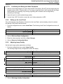
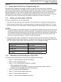
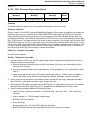
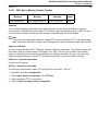
2-5-10. Validating Digital or Video Setup with the Customer
1. Ask the customer to select a typical image that contains the desired range of contrasts.
2. Acquire the image using the keypad or host control. Then print a contrast test. This will print the film
using the default interpolation value (smooth to sharp) to process the image.
Note
Do not use the MPC Print function, because this will print in replicate mode, which is not appropriate.
3. If everything on the image is too light or too dark, adjust the density setting until it is acceptable.
4. After the density setting is acceptable, have the customer select an optimal contrast setting by printing
test films at different contrast settings.
Note
For video setup: If the customer finds the image unacceptable at any combination of density and
contrast levels, it is possible that Gain and Black Level fine tuning needs to be redone using a
different image. It is also possible that the OEM monitor is not adjusted properly.
Kodak DryView 8100 Laser Imager Service Manual
Section 2 – Installation
2000 Rev. C
2-28
5. Have the customer select smooth or sharp image processing. If neither smooth nor sharp is
acceptable to the customer, the interpolation settings may need to be changed (see paragraph 3-7 in
Adjustments).
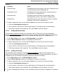
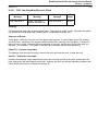
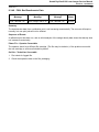
2-6.
Entering Site Information
Enter general descriptive information about the customer site into the system as follows:
1. From the main menu, select Site Info.
The following Site Information screen will display:
Site
Address
Contact
Phone
Fax
Modem Number
Alternate Contact
Location
Notes
2. Click on Edit Site Information.
3. Enter the values requested, and click on Save Changes.
4. Return to the main menu.
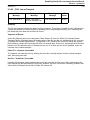
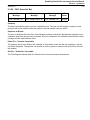
2-7.
Editing the Service History Log
After completing the installation, enter the appropriate data in the Service History Log as follows:
1. From the main menu, click on Service History.
The Service History Log will display. (The log will of course be empty at installation.)
2. Select Add New Log Entry.
The following Service Log Entry form will display:
Date (Year-Mon-Day)
Time (x:xx pm)
Name (Enter your name.)
Summary (Summarize the call in one line.)
Details (Add key details.)
3. Fill in the entry form and click on Save Changes.
2-8.
Backing up the Configuration Settings
Use the MPC backup function to back up the configuration files and copy the files onto a floppy diskette.
See the procedure for backup in paragraph 7-8-12. (You can store the diskette in the IMS floppy drive.)
Kodak DryView 8100 Laser Imager Service Manual
Section 2 – Installation
2000 Rev. C
2-29
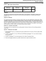
Addendum A. Video Parameter Functions
This addendum provides the following information:
Paragraph
Page
1. Video Setup Screen/Tool Bar Functions . . . . . . . . . . . . . . . . . . . . . . 2-30
2. Selecting a Usable Image for AutoSync . . . . . . . . . . . . . . . . . . . . . . 2-32
3. Hardware problems that Prevent Image Acquisition . . . . . . . . . . . 2-33
4. Uploading a CHP File to Set the Video Parameters . . . . . . . . . . . 2-34
5. Setting the Video Parameters Manually . . . . . . . . . . . . . . . . . . . . . . 2-35
6. Consistency Sweep and Check . . . . . . . . . . . . . . . . . . . . . . . . . . . . . 2-36
View
Page
A. Framing Parameter Effectivity . . . . . . . . . . . . . . . . . . . . . . . . . . . . . . 2-41
B. Horizontal Delay Problems . . . . . . . . . . . . . . . . . . . . . . . . . . . . . . . . . 2-42
C. Vertical Back Porch Problems . . . . . . . . . . . . . . . . . . . . . . . . . . . . . . 2-43
D . Horizontal Active Problems . . . . . . . . . . . . . . . . . . . . . . . . . . . . . . . . 2-44
E. Vertical Active Problems . . . . . . . . . . . . . . . . . . . . . . . . . . . . . . . . . . . 2-45
F. Horizontal Total Banding . . . . . . . . . . . . . . . . . . . . . . . . . . . . . . . . . . . 2-46
G. Pixel Delay Shadowing . . . . . . . . . . . . . . . . . . . . . . . . . . . . . . . . . . . . 2-46
Kodak DryView 8100 Laser Imager Service Manual
Section 2 – Installation
2000 Rev. C
2-30
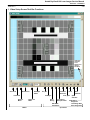
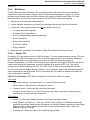
1. Video Setup Screen/Tool Bar Functions
Right click
anywhere
in the
background
while in
Info Mode
iNFO
Pan Mode
Zoom Level
Bit Depth
Mode
Info Mode
Acquire
Viewable
Area Info
AutoSync
Zoom In
Mode
Zoom Out
Mode
Histogram
Video
Survey
Consistency
Sweep & Check
Edit Video
Parameters
Modes
Print
Operations
Save
CHP FIle
Open
CHP File
Image Menu
Image Info
Load Image Data
Save Image Data
Kodak DryView 8100 Laser Imager Service Manual
Section 2 – Installation
2000 Rev. C
2-31
1. Video Setup Screen/Tool Bar Functions (Cont.)
Mode Control
Function
Pan Mode
Provides the ability to drag the image with the mouse.
Info Mode
This is the master mode. It allows use of the mouse to display pixel code values at any
location on the image.
Zoom In/Out Modes
Zoom Level
Allows zooming in or out and setting the zoom level from 25% to 1600%. Note: A zoom
selection of less than 100% will corrupt the image. (This is a Windows problem, not an
image problem.)
Bit Depth
Drop box allows selection of either 8-bit or 10-bit.
Operation Control
Function
Acquire
Grabs and displays a video image using the current video parameter set and pixel bit
depth. If grab fails, an error message displays.
AutoSync
Analyzes the video signal to automatically identify an appropriate set of video parameter values. If AutoSync succeeds, updates the video parameters to the calculated values, automatically grabs the image and displays its. If AutoSync fails, an error message is displayed.
Video Survey
Implemented in Version 2.0 and higher software. Analyzes all nine video input channels
(Analog CA1–CA4, Digital CT1–CT4, and Separate Sync). Displays a report of the video and sync signals found on each channel, indicating presence or absence of nine
different attributes.
Edit Video Parameters
Displays a window for a particular video parameter and shows the current parameter
value. The window allows you to edit the parameter value and press Enter to save it. If
Automatically Acquire is checked, a new image is grabbed after every change.
Consistency Sweep &
Check
Displays a window that allows you to select either the Consistency Check facility or
Consistency Sweep. (Sweep is available only with software Version 2.0 or higher.) Consistency Check runs a single consistency test using the current video parameter values. Consistency Sweep runs a series of consistency tests using the current video parameter values, except Pixel Delay is varied (swept) over a range of values.
Viewable Area Info
Displays a window that shows minimum and maximum pixel code values for the displayed portion of the image. Used to exclude parts of image undesirable for fine tuning.
(Useful for fine tuning Gain and Black Level.)
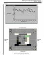
Histogram
Displays a window that graphs the distribution of pixel code values in the image. X axis
is pixel code value. Y axis is pixel count.
Print
Prints the currently displayed mage on film, 1-up, using replicate.
Open CHP File
Displays an “open file” dialog box which allows you to import a set of video parameters
into the IMS from a CHP file.
Save CHP File
Displays a “save file” dialog box which allows you to export the current set of video parameters to a CHP file.
Image Menu:
Access the Image Menu by right-clicking anywhere in the window background while in
Info Mode.
Displays image information for the entire image, regardless of what
portion of the image is displayed.
Image Info
Load Image Data
Save Image Data
Reads and displays raw video image data from a specified image file
stored in MPC. (Standard Windows open file dialog box. Default filter
is *.raw, *.pic)
Writes a file to MPC (as opposed to the IMS) containing the raw video
data for the current image. (Standard Windows save file dialog box.
Default filter is *.raw)
Kodak DryView 8100 Laser Imager Service Manual
Section 2 – Installation
2000 Rev. C
2-32
2. Selecting a Usable Image for AutoSync
Resolve patterns with 1 on, 1 off in both directions are excellent test images to use with AutoSync.
Vertical grill patterns with 1 on, 1 off are also very good. SMPTE patterns often work, as well, but are not
the best choice.
If you do not have a suitable test image, you can use a clinical image if it has the characteristics listed
below. If it does not have these characteristics, the video parameters generated by AutoSync may be
incorrect, and captured image quality will be inferior.
1. The image should remain stable during the entire AutoSync operation. If it does not, results are
unpredictable, since many image captures are done during a single AutoSync operation.
2. At least 1% of the image must be the brightest white. (If not, AutoSync will underestimate brightest
white, and captured images will be too bright, with too much contrast.)
3. At least 1% of the image must be darkest black. (If not, AutoSync will overestimate darkest black, and
captured images will be too dark, with too much contrast.)
4. Light (50% gray or whiter) portions of the image must touch all four sides of the image. Medium to
bright pixels at the edges are best. (If the image does not have these characteristics, AutoSync may
fail to recognize image boundaries, and images may be clipped – or there may be no image capture at
all.)
5. Wide solid black bars (3% gray or blacker) stretching across the entire image should be avoided. (The
bars may be interpreted as composite sync information, and the image may be scrambled.)
6. Include as many edges (text, fine stripes, or checkered patterns) as possible.
7. Test images (especially those with a resolve pattern), or images with lots of text are good.
8. The pixel detection search range, in terms of image width to height ratio, is [0.5, 2.0]. If the image
format exceeds these limits, AutoSync will not calculate correct image parameters.
Note
If AutoSync does not work, try annotating the image with a lot of text, if possible. The goal is to have
at least one significant pixel transition somewhere in every pixel column. Characters with slanted
edges, such as A, O, Q, S, and X are best. Characters with straight edges, such as E, F, H, I, L and
T are not as useful.
Kodak DryView 8100 Laser Imager Service Manual
Section 2 – Installation
2000 Rev. C
2-33
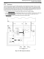
3. Hardware Problems that Prevent Image Acquisition
For video modalities, a Type C Video Board must be installed in PCI Slot 1 (J3) of the IMS motherboard,
and cables must be connected as shown in Figure 2-6 in Installation. Also the Video Board jumpers must
be set correctly. Normally the jumpers have to be reset at installation only if the video source is composite
video passthrough or has an external pixel clock (see Tables 2-1 and 2-2). At this point in installation
these matters should already be taken care of. However, be aware of two potential cabling problems:
1. Double termination of the video signal––If the host monitor image suddenly goes bad when the video
cable is connected to the 8100, the video signal may already be terminated once, and connecting to
the 8100 results in double termination. If this occurs, resolve the problem with the customer. Check for
the problem by observing the host monitor while connecting the video cable to a powered up 8100.
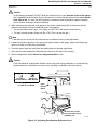
2. Ground loops––These can cause noise that will affect fine tuning of the video parameters. Ground
loops can be avoided by connecting the 8100 to the same power source as the customer modality. If
noise becomes a problem during parameter fine tuning, check for a ground loop as follows:
a. Temporarily disconnect the power cable ground wire from the 8100 by using a 2–prong adapter on
the power cord.
b. Run a ground wire from the 8100 to OEM ground. (There is a convenient ground connection on
the power supply at the back of the 8100.) If the noise goes away, there is a ground loop problem
that must be resolved with the customer.
c. Make sure the normal power (3-prong) ground connection is restored.
Note
Avoid using passive filters or hum eliminators in line with the video source. These can degrade the
quality of the video signal.
Kodak DryView 8100 Laser Imager Service Manual
Section 2 – Installation
2000 Rev. C
2-34
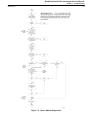
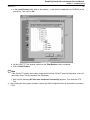
4. Uploading a CHP File to Set the Video Parameters
1. Launch the Video Setup application (available on CD-ROM).
2. Enter the Imager Address, your User Name, and Password. Then click on Login.
Note
For descriptions of the modes and operations of the Video Setup screen and tool bar, see paragraph
1 in this Addendum.
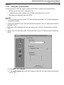
3. On the Video Setup Tool Bar, click on the Open CHP File button. The Open CHP File window will
display:
4. Select the desired CHP file and click on the Open button. The CHP file will be read and the video
parameter values will be set into the imager. All carrier profile parameters will be set correctly.
5. Acquire an image as follows:
a. On the Video Setup screen, set Bit Depth Mode at 8 bit. (This will provide much faster image
transfer time than 10 bit.)
b. Connect the signal source that you will use for video setup to the 8100.
c. On the Video Setup Tool Bar, click on the Acquire button. The test pattern (or other video signal)
should display on the Video Setup screen.
6. Go to paragraph 2-5-7-4 to “tune” the video parameters.
Kodak DryView 8100 Laser Imager Service Manual
Section 2 – Installation
2000 Rev. C
2-35
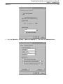
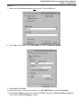
5. Setting the Video Parameters Manually
If AutoSync does not work and you do not have a CHP file, you will have to load each video parameter
manually as described below. You can obtain parameter information from a script file or an OEM
specification sheet, if these are available. The video parameters must be set closely enough so you will
be able to acquire a video image.
1. Launch the Video Setup application (available on CD-ROM).
2. Enter the Imager Address, your User Name, and Password. Then click on Login.
Note
For descriptions of the modes and operations of the Video Setup screen and tool bar, see paragraph
1 in this Addendum.
3. On the Video Setup Tool Bar, click on the Edit Video Parameters button. The Video Parameters
window will display:
4. Use the dropdown Parameter box to select each parameter in turn. The parameter names are
ordered by expected frequency of use, not alphabetically. (The last three parameters in the list, Board
Type, Pixel Clock Frequency, and Pixel Time, are not editable, and are included for information only.)
Note
The Value box will show the new value as you edit the parameters. If Not Specified is checked, the
Value box is dimmed and not editable. This means that the system will choose an appropriate value
automatically rather than use a value that you select.
5. After you enter a new parameter value, press Enter to post the change.
6. Acquire an image as follows:
a. On the Video Setup screen, set Bit Depth Mode at 8 bit. (This will provide much faster image
transfer time than 10 bit.)
b. Connect the signal source that you will use for video setup to the 8100.
c. On the Video Setup Tool Bar, click on the Acquire button. The test pattern (or other video signal)
should display on the Video Setup screen.
7. Go to paragraph 2-5-7-4 to “tune” the video parameters.
Kodak DryView 8100 Laser Imager Service Manual
Section 2 – Installation
2000 Rev. C
2-36
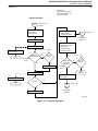
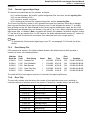
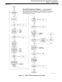
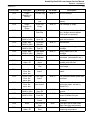
6. Consistency Sweep and Check
Consistency testing measures the amount of variation in individual pixel values over multiple captures of
the same image. As a guideline, the maximum variation should not exceed the values shown in the
following table, when the video parameters are properly fine-tuned. Preferably the variation should be
considerably smaller. Larger variations suggest incorrect parameter settings or some other problem.
Low Freq.
Formats
High Freq.*
Formats
8 bit
16
26
10 bit
62
103
* For the purposes of the table above, high frequency is defined as greater than about 75
MHz pixel frequency, which corresponds to a pixel time of about 13.3 nanoseconds.
Note
Both Consistency Check and Consistency Sweep require a lot of system memory. If sufficient
memory cannot be allocated, the operation fails. At this point, several options are available:
1. The first choice is to temporarily make the active image smaller by reducing the image height
(Vertical Active). (The video source does not need to change.) Reducing width is not
recommended. Making the image smaller results in only part of the image being captured. This
will still allow for valid test results.
2. Run using 8 bits instead of 10 bits, since 8 bits requires less memory.
3. Reboot the IMS. This is the last choice, and will help only if the memory pool has become
fragmented. Rebooting will eliminate the fragmenting and may allow the operation to run.
When the Consistency Sweep & Check button is selected on the Video Setup screen, the following dialog
box displays, allowing you to select either the check or sweep function. (This dialog box and the sweep
function are not available with software Versions earlier than 2.0. With the earlier software versions,
selecting the Consistency Check button initiates the check test.)
Kodak DryView 8100 Laser Imager Service Manual
Section 2 – Installation
2000 Rev. C
2-37
Note
To obtain meaningful results from Consistency Sweep or Check, the video source must remain
stable during the operation, since many captures are made and compared. Also, Horizontal Total
must be correct.
Running a Consistency Check
The video consistency check consists of multiple captures of the same image using the current video
parameter set and pixel bit depth. The minimum and maximum code values for each pixel in the image
are tracked across all captures. After the captures are completed, statistics are calculated on the resulting
pixel code variations. Useful metrics include the average pixel code variation per pixel and the maximum
pixel code variation for the worst case pixel. The latter can be used to fine tune Pixel Delay and verify the
Horizontal Total setting.
The theory behind pixel delay is simple. If pixel delay is set precisely, pixel sampling occurs on the flat
portion of the pixel waveform, between the leading edge and the trailing edge, and after the signal has
settled. Sampled values here will be consistent from one sample to the next. If pixel delay is set
incorrectly, sampling occurs on the leading or trailing edge of the pixel waveform where the slope is large.
Sampled values here will tend to vary significantly because of the slope of the signal.
To run a Consistency Check:
For Systems with Version 2.0 or Higher Software:
1. Acquire an image.
2. Select the Consistency Sweep & Check button on the Video Setup screen to display the Consistency
Sweep and Check dialog box (see the screen above).
3. Check that the Repeat Sweep Parameter is set to 5 (the default). (The other parameters in the dialog
box do not apply to Consistency Check.)
4. Select the Run Check button. The image will be captured several times in succession and the results
will be displayed in the Consistency Check Results window (see next page).
For Systems with Earlier than Version 2.0 Software:
1. Acquire an image.
2. Click on the Consistency Check button on the Video Setup Toolbar. The image will be captured
several times in succession and the results will be displayed in the Consistency Check Results
window:
Kodak DryView 8100 Laser Imager Service Manual
Section 2 – Installation
2000 Rev. C
2-38
Display functions are described as follows:
Display Item
Definition
Number of grabs
The number of image captures for the consistency check.
Average pixel code variation per pixel
The average difference between the minimum and maximum
pixel code values for all pixels in the image over all captures.
Minimum pixel code variation for one
pixel
Details for the one pixel in the image with the smallest
variation over all captures. The minimum variation is shown,
with pixel location and actual minimum and maximum values.
Location 1,1 is the upper left corner of the image. There may
be many pixels with the same minimum variation. The one
shown is the first one encountered.
Maximum pixel code variation for one
pixel
Details for the one pixel in the image with the largest
variation over all captures. The maximum variation is shown,
with pixel location and actual minimum and maximum values.
Location 1,1 is the upper left corner of the image. There may
be many pixels with the same maximum variation. The one
shown is the one first encountered.
Pixel code minimum for all grabs
The minimum pixel code value for all pixels in the image over
all captures.
Pixel code maximum for all grabs
The maximum pixel code value for all pixels in the image over
all captures.
Kodak DryView 8100 Laser Imager Service Manual
Section 2 – Installation
2000 Rev. C
2-39
Running Consistency Sweep
(This function is available only with software Versions 2.0 or higher.) The Consistency Sweep function
automates the process of doing multiple image captures over a range of Pixel Delay values and
inspecting the images for the quality of the pixel sampling. Sampling quality is measured by a maximum
pixel code variation value calculated by the test. The output of the consistency sweep is a graph of the
maximum pixel variation values as a function of Pixel Delay. The graph allows you to choose the optimum
Pixel Delay value, because it shows the leading and trailing edges of the pixel as well as the signal
settling time.
Before running Consistency Sweep, you should complete the video setup procedures through fine-tuning
of the framing parameters. It is especially important that Horizontal Total be set correctly. If possible,
configure the video source to output an image with a great number of large pixel transitions. A resolve
pattern or an image with many text annotations is recommended. A SMPTE test pattern is also useful.
To run Consistency Sweep:
1. Acquire a suitable image.
2. Select the Consistency Sweep & Check button on the Video Setup screen to display the Consistency
Sweep and Check dialog box (see the screen below).
3. Use the default values shown on the screen for the Sweep Parameters. (These parameters have
been calculated by the system based on the values of the currently selected video parameters.). The
Use Default Value boxes should all be checked. (The Sweep Parameters are defined below.)
Sweep Parameter
Definition
Pixel Time
The width of a single pixel in nanoseconds (nseconds). The value is derived from
the video parameters and is not editable.
Repeat
The number of images to capture for each consistency test. One consistency test is
done at each Pixel Delay data point. The default Repeat count is 5.
Start Delay
The start value of the Pixel Delay range in nseconds. Resolution is 0.1 nsecond.
Stop Delay
The stop or end value of the Pixel Delay range in nseconds. Resolution is 0.1
nsecond.
Step Size
The size of each Pixel Delay step in nseconds. Resolution is 1 nsecond.
Step Count
The number of steps in the Pixel Delay range.
Kodak DryView 8100 Laser Imager Service Manual
Section 2 – Installation
2000 Rev. C
2-40
4. Click the Recalculate Parameters button.
5. Click the Run Sweep button to start the consistency sweep. (A Consistency Sweep in Progress
window will display while sweep is running.) When the sweep is completed, a Consistency Sweep
Results window will display:
The attributes to look for when interpreting the graph in the window are the following:
•
The general shape of the graph should include two distinct spikes. These correspond to the
leading and trailing edges of a pixel. (The spikes are caused by the steep slope of the video signal
at the pixel edges.)
•
The distance between the two spike peaks should be about 1 pixel time. In the sample graph
above, the peaks are about 57–19 = 38 nseconds apart. This corresponds closely to the 37.5
nsecond value shown in the Pixel Time box on the Consistency Sweep & Check dialog box.
•
The maximum pixel code variation value in the valley (flat portion between spikes) must be less
than the guideline limit. The limit for low frequency 10-bit data is about 62, so the value shown on
the graph is well below the limit. (The limit for low frequency 8-bit data is about 16.)
The Results window above shows a successful Consistency Sweep test, indicating that Pixel Delay and
Horizontal Total, as well as other parameter values are set correctly. If the graph in the Results window is
missing any of the three attributes described above, check Horizontal Total and verify that it is correct.
The consistency test will not provide good results if Horizontal Total is off by even one pixel. (Also, be
aware that it is difficult to achieve good results if the video source is noisy.) The Results window on the
next page shows a test in which Horizontal Total was off by 2 (too large) from the correct value.
Kodak DryView 8100 Laser Imager Service Manual
Section 2 – Installation
2000 Rev. C
2-41
Vertical Back Porch
Horizontal
Delay
Horizontal
Delay
Vertical Active
View A. Framing Parameter Effectivity
Kodak DryView 8100 Laser Imager Service Manual
Section 2 – Installation
2000 Rev. C
2-42
If the value of Horizontal Delay is too low, a black bar may occur on the left side
of the image. (Horizontal Active will also be affected.)
If the value of Horizontal Delay is too high, part of the image on the left side may be
cut off, and Acquire may fail. A black bar may appear on the right side of the image.
View B. Horizontal Delay Problems
Kodak DryView 8100 Laser Imager Service Manual
Section 2 – Installation
2000 Rev. C
2-43
If the value of Vertical Back Porch is too low, a black bar will appear on the top of the image
and part of the image may be cut off on the bottom.
If the value of Vertical Back Porch is too high, part of the image on the top will be cut off and
a black bar may appear on the bottom of the image. An acquire failure may also occur.
View C. Vertical Back Porch Problems
Kodak DryView 8100 Laser Imager Service Manual
Section 2 – Installation
2000 Rev. C
2-44
If the value of Horizontal Active is too low, part of the image will be cut off.
If the value of Horizontal Active is too high, a black bar will appear on the right side of
the image. An Acquire failure may also occur.
View D. Horizontal Active Problems
Kodak DryView 8100 Laser Imager Service Manual
Section 2 – Installation
2000 Rev. C
2-45
If the value of Vertical Active is too low, the bottom of the image will be cut off.
If the value of Vertical Active is too high, a black bar will appear on the bottom of the
image. The imager may quit acquiring.
View E. Vertical Active Problems
Kodak DryView 8100 Laser Imager Service Manual
Section 2 – Installation
2000 Rev. C
2-46
A
B
C
D
The arrows point to bands caused by incorrect Horizontal Total (also referred to as Clocks
per Line or Pixels per Line). To determine if you have horizontal banding, identify a sharp
area on the image (A above, for example). As you move to the right from A, you will see
the lines become fuzzy until you get to point B. This fuzzy area is a horizontal band. As
you continue to the right from B, the lines again are fuzzy until point C. This is another
band. The bands are usually at equal distances from one another. In this example there
are three bands. The larger the band, the closer you are to the true value of Horizontal Total.
View F. Horizontal Total
If the Pixel Delay value is incorrect, you will see shadowing (ghosting). The
shadow will always be shifted to the same side of the pixel. This is unlike Horizontal
Total shadowing, which is on both sides of the pixel.
View G. Pixel Delay Shadowing
Kodak DryView 8100 Laser Imager Service Manual
Section 3 – Adjustments
2000 Rev. C
3-1
Section 3 – Adjustments
3-1.
Processor Drum Temperature
This procedure must be performed whenever the processor assembly or processor drum is replaced,
whenever the MPC Board is replaced, or if drum temperatures are suspected of causing image quality
problems.
Specification
The temperature measured at the processor drum must be in the range 122.1° – 122.9° C
(252° – 253° F).
Special Tools
Temperature meter with probe and block
Service PC with Internet Explorer 4.0 (or higher)
Note
A temperature meter and probe with a bar type element must be used to perform this procedure.
Probes with circular type elements will not provide accurate readings. The temperature meter and
probe must be calibrated together as a pair at least once per year. If the probe breaks, a new probe
and the meter must be sent in for calibration. Refer to paragraph 5-2 for details.
Note
The temperature meter must be at room temperature when performing this procedure. If the meter
has been brought in from a hot or cold vehicle, allow it to acclimate to room temperature before use.
Measurement Setup
1. Power up and allow the imager to warm to operating temperature (READY).
2. Lift the upper hood and set the Service Switch in the Service position.
3. Prepare the temperature meter for use as follows:
a. Install the block on the temperature meter probe as shown in Figure 3-1.
b. Clean the probe with alcohol.
c. Set the temperature meter to display in Celsius (C).
2
inches
Figure 3-1. Positioning the Temperature Probe Block
Kodak DryView 8100 Laser Imager Service Manual
Section 3 – Adjustments
2000 Rev. C
3-2
Measurement
1. Release the processor cover clamps.
2. Remove the two attaching screws, and remove the processor left side plate (see Figure 3-2).
!
Caution
Hot Surface
The processor drum and rollers are hot. Take care when working in the area of the processor.
3. Lift the processor cover slightly and insert the temperature meter probe under the cover at the center
of the drum as shown in Figure 3-2. Position the probe block just below the cover handle (see
Figure 3-2).
4. Lower the cover to secure the probe in place.
5. Allow the temperature reading on the meter to stabilize. The meter should indicate 122.1° to 122.9°. If
it does not, perform the following adjustment.
Figure 3-2. Positioning the Temperature Probe
Kodak DryView 8100 Laser Imager Service Manual
Section 3 – Adjustments
2000 Rev. C
3-3
Adjustment
1. Connect your Service PC to the DryView 8100. Then power up the PC and use Internet Explorer to
access the DryView 8100 web page.
2. Click on Authorized Field Engineer, then Continue.
3. Enter your user name and password.
4. From the MPC Main Menu, select Configuration.
5. Select Processor. The Processor Configuration screen will display the current temperature.
Processor Temperature 122.44 degrees C
Temperature Offset –0.58 degrees C
Processor Set Point 122.50 degrees C
6. Select Calibrate Processor Temperature.
7. On the Processor Temperature Calibration screen, enter the temperature measured by the meter.
8. Click the Perform Calibration button. The MPC software will adjust the drum temperature to the set
point.
9. Click the Manual Refresh button to observe the temperature change on the Processor
Configuration screen. Allow time for the adjustment to occur. (The time will vary, depending on how
far out of spec the measured temperature was.)
10. When MPC indicates that the temperature is in spec, check drum temperature again with the meter to
confirm the adjustment.
Note
The adjustment process may have to be repeated to obtain proper drum temperature.
Kodak DryView 8100 Laser Imager Service Manual
Section 3 – Adjustments
2000 Rev. C
3-2.
!
3-4
Processor Drum RTD
Caution
The following calibration procedure is done at the manufacturing site, and should rarely have to be
performed in the field. It is included here for reference. DO NOT perform this procedure unless
directed to do so by service engineering. Misadjustment can cause additional machine problems.
Specification
Output of the Voltage to Frequency Converter on the MCS Board (TP7) is 99.5 to 100.5 Khz.
Special Tools
Calibrated digital multimeter with frequency measurement capability (e.g., Fluke 87) or an Oscilloscope
Adjustment
1. Remove the rear panel and set the Service Switch in the Service position.
2. With power off, remove the connector plug from J17 on the MCS board. (This disconnects the RTD
from the circuit.)
3. Remove jumper JP7 from the NORM position and place it in the CAL position (see Figure 3-3).
4. Connect the digital multimeter (set to measure frequency) or a scope to TP7 on the MCS Board.
5. Adjust pot VR1 on the MCS board so that the measured frequency is 99.5 to 100.5 KHz.
6. Power off. Then replace jumper JP7 in the NORM position, reconnect the RTD connector plug to J17,
set the Service Switch to its normal operating position, and replace the rear panel.
Figure 3-3. Calibrating the Processor Drum RTD
Kodak DryView 8100 Laser Imager Service Manual
Section 3 – Adjustments
2000 Rev. C
3-3.
3-5
Processor Film Diverter Assembly (Stripper)
Specification
Gap between diverter blade and drum end caps must be 0.015 to 0.020 inch (0.38 to 0.50 mm).
Required Tools
Feeler gauges
M2.5 Allen wrench
Adjustment
1. Power down. Then raise the upper hood and release the two drum cover latches.
!
Caution
Hot Surface
The heat shield and the surface of the processor drum may be hot. Take care in the following
procedure.
2. Lift and remove the heat shield to gain access to the film diverter attaching screws (see Figure 3-4).
3. Loosen the two diverter attaching screws.
4. Lower the heat shield and open the drum cover.
5. Set the gap between the diverter and drum end caps to 0.015 to 0.020 inch (0.38 to 0.50 mm). Rotate
the drum and remeasure to ensure gap consistency around the drum.
Note
Reposition the drum cover and heat shield as necessary in the following steps.
6. Tighten the two attaching screws.
7. Verify the gap. Adjust as necessary to achieve the specification.
Figure 3-4. Adjusting the Film Diverter Blade Gap
Kodak DryView 8100 Laser Imager Service Manual
Section 3 – Adjustments
2000 Rev. C
3-4.
3-6
Optics Translation Speed and SOP Delay
This adjustment must be performed if any of the following is replaced: the translation motor, the film
centering motor, the optics home sensor, or the optics module. If translation speed is too fast, the image
may appear stretched. If Start of Page (SOP) is out of adjustment, the image will be shifted right or left on
the page.
Specification
•
Left and right margins on the page must be equal, at 7 mm each.
•
Image must not appear stretched or shortened.
•
No clear margins should show on the sides of the film.
Special Tools
Service PC with Internet Explorer 4.0 (or higher)
Metric ruler with millimeter units
Preliminary
1. Connect your Service PC to the DryView 8100. Then power up the PC and use Internet Explorer to
access the DryView 8100 web page.
2. Click on Authorized Field Engineer, then Continue.
3. Enter your user name and password.
4. From the MPC Main Menu, select Configuration.
5. From the Configuration menu, select System.
6. From the System Configuration menu, set Maximum Imagable Columns at 4361 (side format).
7. Return to the Configuration menu and select Optics.
8. From the Optics Configuration menu, select Adjust Speed & Delay. The following screen will
display:
Kodak DryView 8100 Laser Imager Service Manual
Section 3 – Adjustments
2000 Rev. C
3-7
Measurement
Preliminary
1. If the image is offset to the left or right so far that the margin is cut off, center the image approximately
as follows:
a. Enter a negative value (e.g., –3 mm) in the X-Left or X-Right box, as appropriate.
b. Click on the Perform Adjustment button.
c. Enter a new value (+ or –, as necessary) to approximately center the image.
Fine Measurement
1. Click on Print Density Test to print a density test sheet.
2. At the center of the film from top to bottom (as shown in the illustration) use a ruler calibrated in
millimeter units to measure X-Left (distance between the edge of the film and the edge of the image
data).
3. Enter the measured value in the X-Left box on the screen.
4. Use the ruler to measure X-Right directly across from where you measured the left margin on the film.
5. Enter the measured value in the X-Right box on the screen.
Adjustment
1. Click on the Perform Adjustment button. (MPC will automatically adjust optics speed and SOP
delay.)
2. After the adjustment is performed, click on Print Density Test to print a new density test sheet.
3. Check the test sheet to confirm that the margins are according to specification.
Kodak DryView 8100 Laser Imager Service Manual
Section 3 – Adjustments
2000 Rev. C
3-5.
3-8
Densitometer Reference Level
If the densitometer board or the light source board is replaced, the light source reference level must be
checked and adjusted.
Specification
Reference level must be within the range shown on the Densitometer Configuration Screen in MPC.
Target value is 32500 (hex).
Special Tools
Service PC with Internet Explorer 4.0 (or higher)
Pot Adjustment Tool
Preliminary
Note
The following procedure should be performed in subdued lighting. Make the area as dark as
possible. Also, do not attempt the procedure while the machine is in a print cycle.
1. Connect your Service PC to the DryView 8100. Then power up the PC and use Internet Explorer to
access the DryView 8100 web page.
2. Click on Authorized Field Engineer, then Continue.
3. Enter your user name and password.
4. From the MPC Main Menu, select Configuration.
5. From the Configuration Menu, select Densitometer. The Densitometer Configuration Screen shown
below will display. (You may have to wait up to 5 minutes for the full screen gauge to display.)
Adjustment
1. Lift the upper hood.
2. Remove four screws attaching the densitometer module and slide the module out about 3 inches to
access the light source board (see Figure 3-5).
3. Adjust pot R3 on the light source board as follows:
•
For current light source boards (see Figure 3-5): Turn R3 (a multi-turn pot) fully CCW until it clicks.
•
For early version light source boards: Turn R3 (a one-turn pot) fully CW.
Kodak DryView 8100 Laser Imager Service Manual
Section 3 – Adjustments
2000 Rev. C
!
3-9
Caution
In the following procedure DO NOT allow the reference bar to move past the center of the gauge.
Also, regardless of the Revision level of the board, it is critical that the reference bar never moves
from right to left. If it does, the A/D converter is overdriven and will produce negative readings
from a cal film, resulting in a failed calibration.
4. While observing the reference level gauge on the screen, slowly adjust R3 as follows so that the
reference bar begins to move toward the center of the gauge.
•
For current boards (see Figure 3-5): Slowly turn R3 CW. (It will require several turns.)
•
For early version boards: Slowly turn R3 CCW. (This is a one-turn pot.)
Note
It will take up to a minute for the reference bar to complete moving in the adjustment.
5. Center the reference level bar in the green and yellow areas on the gauge. Adjust until the gauge
value is as close to 32500 (hex) as possible.
6. Close the upper hood and verify that the reading does not change significantly.
7. Open the hood and reattach the densitometer module to the frame (four screws).
8. After the adjustment, select Return to Configuration Menu to exit.
!
Caution
If the Densitometer Configuration Screen is active any time during calibration or normal printing,
Dpatch timeouts or calibration errors will occur, resulting in calibrations and job reprints.
Pot R3 on
Pot R3 on
Current Boards Older Boards
Identifying the Version
of Light Source Board
Light
Source
Board
R
3
Remove two screws
from each side to pull
assembly out.
8100–164L
Figure 3-5. Adjusting Densitometer Reference Level
Kodak DryView 8100 Laser Imager Service Manual
Section 3 – Adjustments
2000 Rev. C
3-6.
3-10
Laser Dynamic Range
Laser dynamic range is automatically tested at power up and whenever a test calibration occurs. It is
defined as the ratio of maximum laser power minus power monitor offset to minimum laser power minus
power monitor offset (Max power – Offset)/ (Min power – Offset). Power monitor offset is the power
monitor output value measured when the laser is turned off. A laser dynamic range failure can be caused
by a bad power monitor offset value.
!
Caution
Do not perform this procedure unless you are sure it is required. It should be performed only when
an MCS Board or the Scanner Assembly has been replaced, or P604 has occurred. Unnecessary
adjustment can degrade image quality.
Note
This procedure cannot be run while the machine is in Service mode. (With the machine in Service
mode, the laser dynamic range is 1.) If the machine has been in Service mode, set the Service
Switch to User mode and cycle power before performing the procedure. Also, the upper hood, front
door and rear service panel must be closed for the adjustment to work.
Specification
Laser dynamic range is 100 to 200. Nominal desired value is 150. Values between 140 and 160 are
acceptable.
Required Tools
Service PC with Internet Explorer 4.0 (or higher)
Measurement
1. Connect your Service PC to the DryView 8100. Then power up the PC and use Internet Explorer to
access the DryView 8100 web page.
2. Click on Authorized Field Engineer, then Continue.
3. Enter your user name and password.
4. From the MPC Main Menu, select Configuration.
5. From the Configuration menu select Optics.
6. Check that the laser dynamic range is between 140 and 160. If it is, do not adjust.
Adjustment
1. From the Optics Configuration menu, select Adjust Laser Dynamic Range. The Adjust Laser
Dynamic Range screen will display.
2. Click on Start Adjustment to initiate automatic adjustment through the MPC. (The adjustment may
take a few minutes.) In some cases you will have to repeat the adjustment several times. As you do,
note whether the measured values are improving.
3. After the adjustment is completed, run a calibration print before running any other print.
!
Caution
If a print is initiated before calibration, P622 (Media LUT Non-Monotonic) will occur.
Kodak DryView 8100 Laser Imager Service Manual
Section 3 – Adjustments
2000 Rev. C
3-7.
3-11
Interpolation Values for Smooth and Sharp Via the DryView V2 Keypad
The parameters listed below are configurable through the NVRAM Setup Menu of the DryView V2
Keypad:
Parameter
Default Value
Smooth Beta Value
Sharp Beta Value
15
2
Procedure
Enter new configuration values for smooth and sharp, or enter the default values as follows. (If current
values are missing or wrong, and you don’t know the optimum values, enter the default values.)
1. On the DryView V2 Keypad, simultaneously press and hold the Print, Erase, and Sequential Store
keys to display the NVRAM Setup Menu (see illustration below).
2. Use the Smooth Beta Value key to achieve the desired number on the key display.
3. Use the Sharp Beta Value key to achieve the desired number on the key display.
4. To return to the Main Menu, press Return.
Kodak DryView 8100 Laser Imager Service Manual
Section 3 – Adjustments
2000 Rev. C
3-12
BLANK PAGE
Kodak DryView 8100 Laser Imager Service Manual
Section 4 – Disasssembly/Reassembly
2000 Rev. B
4-1
Section 4 – Disassembly/Reassembly
4-1.
4-1-1.
Front Door and Rear Panel Assemblies
Front Door Filter
1. Open the front door.
2. Remove six attaching screws (Figure 4-1).
!
Warning
When the front door is open, all motors and the laser are disabled, but power remains applied to
the system.
3. Pull off the cover (with gasket and filter retainer).
4. Remove the filter.
3
444
4
2
Figure 4-1. Replacing the Front Door Filter
8100–76L
Kodak DryView 8100 Laser Imager Service Manual
Section 4 – Disasssembly/Reassembly
2000 Rev. B
4-1-2.
4-2
Rear Panel
1. Press the Open Door key to close the film cartridge.
2. Remove nine attaching screws from the rear panel (Figure 4-2).
!
Warning
When the rear panel is removed, all motors and the laser are disabled. However, power remains
applied to the system. If you need to activate the motors, actuate the Service Switch. Be aware that
hazardous voltages are present in some areas of the DryView 8100. These voltages can cause
severe injury or death.
3. Pull the top of the rear panel back, and lift up to remove the panel feet from the slots in the machine
base.
4. Set the rear panel aside.
Note
During reassembly ensure that the rear cover interlock is engaged before tightening the screws.
2
3
8100–77L
Figure 4-2. Removing the Rear Panel
Kodak DryView 8100 Laser Imager Service Manual
Section 4 – Disasssembly/Reassembly
2000 Rev. B
4-2.
!
4-2-1.
4-3
Film Processor Assembly
Caution
Any circuit board that is replaced in the DryView 8100 must be returned to Kodak for rework or
disposed of properly. Printed circuit boards contain lead.
Processor Interface Board
1. Press the Open Door key to close the film cartridge.
2. Remove power and disconnect the power cord.
!
Warning
When the power cord is plugged in, hazardous voltages are present in some areas of the DryView
8100. These voltages can cause severe injury or death.
3. Open the machine upper hood and remove the back panel.
4. Disconnect the drum cable from the cover box over the Processor Interface Board (Figure 4-3).
5. Remove four attaching screws from the cover box.
6. Lift the box free from the Processor Interface Board.
7. Remove four attaching screws from the corners of the board, and remove the board.
4
5
8100–200L
Figure 4-3. Removing the Processor Interface Board
Kodak DryView 8100 Laser Imager Service Manual
Section 4 – Disasssembly/Reassembly
2000 Rev. B
4-2-2.
4-4
Processor Drum
Disassembly
1. Remove power and disconnect the power cord.
!
Warning
When the power cord is plugged in, hazardous voltages are present in some areas of the DryView
8100. These voltages can cause severe injury or death.
2. Open the machine upper hood.
3. Disconnect the two cables extending from the drum (See View A in Figure 4-4).
4. Lift the belt tensioner (View A) to provide slack in the belt, and remove the belt from the drum pulley.
!
Caution
Hot Surface
When the imager is initially powered down, the processor drum and rollers are hot. Take care when
removing the drum.
5. Release the clamps (View B) from the cover of the processor and open the processor cover.
!
Caution
The surface of the drum is easily damaged by fingernails and jewelry. Handle the drum with one
hand on the large pulley and the other hand on the opposite endcap. Do not touch the silicone
surface of the drum.
6. Lift the drum from the processor and lay it on a flat, stable surface. (The pulley will prevent the silicone
surface of the drum from touching the flat surface.) As an option, you can place the drum in the cradle
made by the processor cover assembly.
Note
Whenever a new drum is installed, the processor temperature adjustment must be performed
(procedure 3-1).
Kodak DryView 8100 Laser Imager Service Manual
Section 4 – Disasssembly/Reassembly
2000 Rev. B
4-5
4
3
8100–199L
6
5
Figure 4-4. Removing the Processor Drum
Kodak DryView 8100 Laser Imager Service Manual
Section 4 – Disasssembly/Reassembly
2000 Rev. B
4-2-3.
4-6
Processor Rollers and Related Parts
Disassembly
1. Remove power and disconnect the power cord.
!
Warning
When the power cord is plugged in, hazardous voltages are present in some areas of the DryView
8100. These voltages can cause severe injury or death.
2. Open the machine upper hood and allow the processor to cool before proceeding.
!
Caution
Hot Surface
When the imager is initially powered down, the processor drum and rollers are hot. Take care when
removing the rollers.
3. Release the two clamps and open the processor cover.
4. To remove the rollers, simply lift each roller from the retainer clips at each end (Figure 4-5).
Note
The bearings on the ends of each roller are loose. Take care not to lose the bearings or the springs
that they mount on in the retainer clips.
Reassembly
1. Install a bearing on each end of the roller, and make sure each retainer clip includes a spring.
2. Insert the bearings (with roller) into the retainer clips as shown in the inset in Figure 4-5. Check that:
(a) each roller rotates freely, (b) each bearing is free to slide against the spring in the retainer, and (c)
the springs are not bent.
Figure 4-5. Removing the Processor Rollers
Kodak DryView 8100 Laser Imager Service Manual
Section 4 – Disasssembly/Reassembly
2000 Rev. B
4-2-4.
4-7
Processor Motor (Step 5)
1. Open the front door to close the film cartridge. Then remove power and disconnect the power cord.
!
Warning
When the power cord is plugged in, hazardous voltages are present in some areas of the DryView
8100. These voltages can cause severe injury or death.
2. Open the machine upper hood and remove the back panel.
3. Lift the belt tensioner (Figure 4-6) to provide slack in the belt, and remove the belt from the motor
pulley.
4. Disconnect the motor electrical plug from the cable (Figure 4-6).
5. Remove four screws and remove the processor motor.
Belt
3
5
4
Figure 4-6. Removing the Processor Motor
8100–198L
Kodak DryView 8100 Laser Imager Service Manual
Section 4 – Disasssembly/Reassembly
2000 Rev. B
4-2-5.
4-8
Processor Film Diverter Assembly
1. Remove power and disconnect the power cord.
!
Warning
When the power cord is plugged in, hazardous voltages are present in some areas of the DryView
8100. These voltages can cause severe injury or death.
2. Open the machine upper hood.
!
Caution
Hot Surface
When the imager is initially powered down, the processor drum and rollers are hot. Take care when
working in the area of the processor.
3. Lift up the heat shield (Figure 4-7).
4. Remove two screws and remove the film diverter assembly (including stripper and felt pad).
Note
When you replace a film diverter assembly, refer to the adjustment procedure, paragraph 3-3.
Figure 4-7. Removing the Processor Diverter and Felt Pad
Kodak DryView 8100 Laser Imager Service Manual
Section 4 – Disasssembly/Reassembly
2000 Rev. B
4-3.
4-9
Roller Set Assemblies
1. Open the front door to close the film cartridge. Then remove power and disconnect the power cord.
!
Warning
When the power cord is plugged in, hazardous voltages are present in some areas of the DryView
8100. These voltages can cause severe injury or death.
2. Open the machine upper hood and remove the machine back panel (paragraph 4-1-2).
3. Lift the belt tensioner and remove the transport/processor drive belt (Rear View in Figure 4-8).
4. For the transport roller assembly located at the rear base of the processor only: Remove two screws
and remove the back latch plate (Rear View).
5. For each transport roller set asembly:
a. Remove one attaching screw from each end of the assembly (Rear View and Front View).
b. Pull the roller assembly out of its slot (Front View).
3
5
4
5
5
5
Figure 4-8. Removing the Transport Roller Set Assemblies
Kodak DryView 8100 Laser Imager Service Manual
Section 4 – Disasssembly/Reassembly
2000 Rev. B
4-4.
4-4-1.
4-10
Densitometer Assembly
Densitometer Module
1. Remove power and disconnect the power cord.
!
Warning
When the power cord is plugged in, hazardous voltages are present in some areas of the DryView
8100. These voltages can cause severe injury or death.
2. Open the machine upper hood.
3. Remove four attaching screws (Figure 4-9).
4. Slide the Densitometer Module out far enough to gain access to the RJ45 plug on the right side of the
densitometer box.
5. Disconnect the RJ45 plug from the densitometer box.
6. Remove the module and set it on a work bench.
Figure 4-9. Removing the Densitometer Module
Kodak DryView 8100 Laser Imager Service Manual
Section 4 – Disasssembly/Reassembly
2000 Rev. B
4-4-2.
4-11
Densitometer/Exit Sensor (S9)
1. Power down and remove the Densitometer Module (4-4-1).
!
Warning
When the power cord is plugged in, hazardous voltages are present in some areas of the DryView
8100. These voltages can cause severe injury or death.
2. Remove the right side screw of the sensor cover box (Figure 4-10).
3. Loosen the left side screw of the cover box and pivot the cover box over and to the left to expose the
sensor.
4. Disconnect the insert plug from the sensor connector.
!
Caution
If the sensor is to be replaced, be very careful not to damage the clips during removal. Also be
careful not to damage the fragile actuator of the sensor during disassembly and reassembly.
5. Gently rock the sensor back and forth to disengage its clips from the chassis.
5
2
3
4
8100–71L
Figure 4-10. Removing the Densitometer/Exit Sensor
Kodak DryView 8100 Laser Imager Service Manual
Section 4 – Disasssembly/Reassembly
2000 Rev. B
4-4-3.
!
4-12
Densitometer Light Source Assembly
Caution
Any circuit board that is replaced in the DryView 8100 must be returned to Kodak for rework or
disposed of properly. Printed circuit boards contain lead.
1. Power down and remove the Densitometer Module (4-4-1).
!
Warning
When the power cord is plugged in, hazardous voltages are present in some areas of the DryView
8100. These voltages can cause severe injury or death.
2. Disconnect the two electrical plugs from the board (Figure 4-11).
3. Remove two attaching screws and remove the light source board.
4. After reassembly and reinstallation of the Densitometer Module, adjust the light source reference level
as described in paragraph 3-5 in Adjustments.
2
3
8100–72L
Figure 4-11. Removing the Light Source Board
Kodak DryView 8100 Laser Imager Service Manual
Section 4 – Disasssembly/Reassembly
2000 Rev. B
4-4-4.
!
4-13
Densitometer Board
Caution
Any circuit board that is replaced in the DryView 8100 must be returned to Kodak for rework or
disposed of properly. Printed circuit boards contain lead.
1. Power down and remove the Densitometer Module (4-4-1).
!
Warning
When the power cord is plugged in, hazardous voltages are present in some areas of the DryView
8100. These voltages can cause severe injury or death.
2. Remove four hex nuts and washers and remove the box from the densitometer (Figure 4-12).
3. Disconnect the RJ45 connector from the densitometer.
4. Remove five attaching screws and remove the densitometer board.
5. After reassembly and reinstallation of the Densitometer Module, adjust the densitometer light source
reference level as described in paragraph 3-5 in Adjustments.
4
2
3
8100–73L
Figure 4-12. Removing the Densitometer
Kodak DryView 8100 Laser Imager Service Manual
Section 4 – Disasssembly/Reassembly
2000 Rev. B
4-5.
!
4-14
Local Panel Assembly
Caution
Any circuit board that is replaced in the DryView 8100 must be returned to Kodak for rework or
disposed of properly. Printed circuit boards contain lead.
1. Remove power and disconnect the power cord.
!
Warning
When the power cord is plugged in, hazardous voltages are present in some areas of the DryView
8100. These voltages can cause severe injury or death.
2. Open the upper hood.
3. Remove four screws and remove the panel (Figure 4-13).
4. Disconnect one RJ45 plug.
2
Upper
Hood
3
4
8100–74L
Figure 4-13. Removing the Local Panel
Kodak DryView 8100 Laser Imager Service Manual
Section 4 – Disasssembly/Reassembly
2000 Rev. B
4-6.
4-6-1.
4-15
Film Pickup Assembly
Film Pickup Module
1. Remove the supply cartridge.
!
Warning
When the power cord is plugged in, hazardous voltages are present in some areas of the DryView
8100. These voltages can cause severe injury or death.
2. Remove power and disconnect the power cord.
3. Open the front door and remove the back panel.
4. Check that the film pickup carriage is in the home (retracted) position (sucker cups are up). If it is not,
proceed as follows: While holding the film pickup carriage from the bottom to keep it from dropping,
pry the release tab out (see Rear View) to disengage the motor drive gear. Then lift the carriage up to
the retracted (home) position, and let go of the release tab.
5. Remove two attaching screws from the front (Front View in Figure 4-14).
6. Disconnect two electrical cables (Rear View in Figure 4-14). (One plugs into the Film Pickup
Assembly. The other is the cable to the rollback motor, which should be disconnected to avoid
damage to it.)
7. Remove two attaching screws from the back side.
8. The Film Pickup Assembly is hanging from a rod via hooks. With one hand under the heel of the
pickup module and the other supporting the top, carefully lift up to remove the top hooks from the rod.
Then tip the Film Pickup Assembly slightly to the left and lower it to remove it.
!
Caution
Be careful in reassembly to avoid damaging wires and connectors.
Figure 4-14. Removing the Film Pickup Assembly
Kodak DryView 8100 Laser Imager Service Manual
Section 4 – Disasssembly/Reassembly
2000 Rev. B
4-6-2.
4-16
Film Pickup Cups
1. Remove the supply cartridge.
!
Warning
When the power cord is plugged in, hazardous voltages are present in some areas of the DryView
8100. These voltages can cause severe injury or death.
2. Remove power and disconnect the power cord.
3. Remove each film pickup cup as follows:
a. Insert a small flat-blade screwdriver into the slot at the center of each cup and turn
counterclockwise to remove the cup and hub (Figure 4-15).
b. Use the flat blade screwdriver to pry the hub from the cup.
4. When reassembling the cups, do not overtighten the hubs.
Vacuum
Hose
Hub
Cup
8100–75L
Figure 4-15. Replacing the Pickup Cups
Kodak DryView 8100 Laser Imager Service Manual
Section 4 – Disasssembly/Reassembly
2000 Rev. B
4-6-3.
4-17
Film Pickup Heel Pad
1. Remove the supply cartridge.
!
Warning
When the power cord is plugged in, hazardous voltages are present in some areas of the DryView
8100. These voltages can cause severe injury or death.
2. Remove power and disconnect the power cord.
3. Remove the Film Pickup Module (4-6-1) and set it on a stable work surface.
4. Carefully peel off the pad that covers the film pickup heel, taking care not to damage the two sensor
actuators that extend through the heel (see Figure 4-16).
5. Use alcohol wipes to clean off the adhesive remaining on the heel after the pad is removed. Make
sure all the adhesive is removed.
Note
Make sure all the old adhesive is removed from the heel. Check the edges of the heel. If the new
heel pad does not adhere properly, it could hang up and cause problems.
6. Install a new pad as follows:
a. Peel off the protective layer from the adhesive surface (inside) of the pad.
b. Apply one edge of the pad to the heel, and gradually press the adhesive surface of the pad to the
heel, working from one side toward the other side of the heel. Make sure you do not leave any air
bubbles between the pad and the heel.
Figure 4-16. Replacing the Pad on the Film Pickup Heel
Kodak DryView 8100 Laser Imager Service Manual
Section 4 – Disasssembly/Reassembly
2000 Rev. B
4-6-4.
4-18
Film Pickup Optical Sensors (S3, S4, S5, S10)
1. Remove the supply cartridge.
!
Warning
When the power cord is plugged in, hazardous voltages are present in some areas of the DryView
8100. These voltages can cause severe injury or death.
2. Remove power and disconnect the power cord.
3. Remove the Film Pickup Module (4-6-1).
4. Position the film carriage as necessary to gain clear access to the sensor (Figure 4-17).
5. Remove the desired sensor as follows:
a. Disconnect the electrical plug from the sensor.
!
Caution
If the removed sensor is to be reinstalled, be very careful not to damage the mounting clips during
removal. Also be careful not to damage the fragile actuators of Film Surface Sensor S4 and Film
Out Sensor S5 during disassembly and reassembly.
b. Gently rock the sensor back and forth to disengage its mounting clips from the chassis sheet
metal.
6. When replacing a sensor, make sure that the sensor clips are properly seated in the sheet metal.
Figure 4-17. Optical Sensor Locations
Kodak DryView 8100 Laser Imager Service Manual
Section 4 – Disasssembly/Reassembly
2000 Rev. B
4-6-5.
4-19
Film Pickup Motor (DCM2)
1. Remove the supply cartridge.
!
Warning
When the power cord is plugged in, hazardous voltages are present in some areas of the DryView
8100. These voltages can cause severe injury or death.
2. Remove power and disconnect the power cord.
3. Remove the Film Pickup Module (4-6-1).
4. Disconnect the electrical plug (Figure 4-18).
5. Remove the spring from the motor bracket.
6. Remove two shoulder screws and washers. (The washers may fall off after the shoulder screws are
removed.)
7. Remove the motor.
Figure 4-18. Replacing the Pickup Motor
Kodak DryView 8100 Laser Imager Service Manual
Section 4 – Disasssembly/Reassembly
2000 Rev. B
4-6-6.
4-20
Film Pickup Vacuum Pump
Disassembly
1. Remove the supply cartridge.
!
Warning
When the power cord is plugged in, hazardous voltages are present in some areas of the DryView
8100. These voltages can cause severe injury or death.
2. Remove power and disconnect the power cord.
3. Remove the Film Pickup Module (4-6-1).
4. Disconnect the vacuum hose from the pump (see Figure 4-19).
5. Remove the attaching screw securing the loop clamp, and remove the pump and adhesive foam pad.
Reassembly
1. Before replacing a pump, remove any foam residue from the mounting location and clean the surface.
2. With the loop clamp on the pump, position the pump (with foam pad) to establish the mounting
location. (After the pump and foam padding are secured in position in step 3, the loop clamp must be
attached with its mounting screw.)
3. Peel the protective cover from the foam and press down to adhere the foam (and pump) to the
mounting surface. Then complete reassembly.
Figure 4-19. Removing the Film Pickup Vacuum Pump
Kodak DryView 8100 Laser Imager Service Manual
Section 4 – Disasssembly/Reassembly
2000 Rev. B
4-7.
4-7-1.
4-21
Rollback Assembly
Rollback Module
Disassembly
1. Remove the supply cartridge.
2. Press the Power Switch OFF, but do not disconnect the power cord as yet.
3. Open the front door and remove the rear panel of the machine.
4. Actuate the Service Switch by unscrewing the actuator bolt (Rear View in Figure 4-20).
5. Press the Power Switch ON while observing the elevator from the front of the machine. The elevator
will begin moving to its down position (Front View). (This will take a few minutes.)
!
Warning
When the power cord is plugged in, hazardous voltages are present in some areas of the DryView
8100. These voltages can cause severe injury or death.
6. When the elevator is all the way down (sensor blocked), press the Power Switch OFF and disconnect
the power cord.
7. Manually turn the rollback knob to move the rollback roller to about the middle of the cartridge tray.
8. Disconnect the electrical plug for the rollback motor (Rear View).
9. Disconnect the plug for the rollback sensors (Rear View).
10. Disconnect the cable plug from the Barcode Reader Board (Rear View).
11. Remove the two screws attaching the base of the Rollback Module (Front View).
12. Remove three screws attaching the top bracket of the module (Front View).
13. Carefully slide the module out the front of the machine and set it on a work surface. (See next page.)
4
12
8
7
10
9
11
Figure 4-20. Removing the Rollback Module
Kodak DryView 8100 Laser Imager Service Manual
Section 4 – Disasssembly/Reassembly
2000 Rev. B
Reassembly
Reassembly is essentially the reverse of disassembly. Make sure when you install the module that the
bottom left of the assembly slides in along the slide track on the base (Front View).
!
Caution
Take care not to damage wiring when you slide the module in. Make sure the barcode cable is
routed properly after reassembly.
4-22
Kodak DryView 8100 Laser Imager Service Manual
Section 4 – Disasssembly/Reassembly
2000 Rev. B
4-7-2.
4-23
Rollback Motor (DCM1)
1. Remove the supply cartridge, power down, and remove the Rollback Module (4-7-1).
!
Warning
When the power cord is plugged in, hazardous voltages are present in some areas of the DryView
8100. These voltages can cause severe injury or death.
2. Turn the rollback knob to position the rollback motor for easy access to its attaching screws.
3. Remove three screws to free the motor from its coupler bracket (Figure 4-21).
Note
To access the bottom screw you will have to lift up the rollback roller.
4. Remove the coupler vane from the bracket.
5. Reassembly is essentially the reverse of disassembly.
!
Caution
Take care not to damage wiring when you replace the Rollback Module in the machine. Make sure
the barcode cable is routed properly after reassembly.
Figure 4-21. Removing the Rollback Motor
Kodak DryView 8100 Laser Imager Service Manual
Section 4 – Disasssembly/Reassembly
2000 Rev. B
4-7-3.
4-24
Cartridge Present Sensor (S1)
1. Remove the supply cartridge, power down, and remove the Rollback Module (4-7-1).
!
Warning
When the power cord is plugged in, hazardous voltages are present in some areas of the DryView
8100. These voltages can cause severe injury or death.
2. Disconnect the electrical plug from the sensor (Figure 4-22).
!
Caution
If the same sensor is to be replaced, be careful not to damage the mounting clips during removal.
3. Gently rock the sensor back and forth to disengage the mounting clips.
4. When replacing a sensor, make sure that the mounting clips are securely seated in the sheet metal.
5. Reassembly is essentially the reverse of disassembly.
!
Caution
Take care not to damage wiring when you replace the Rollback Module in the machine. Make sure
the barcode cable is routed properly after reassembly.
Figure 4-22. Removing the Cartridge Present Sensor
Kodak DryView 8100 Laser Imager Service Manual
Section 4 – Disasssembly/Reassembly
2000 Rev. B
4-7-4.
4-25
Rollback Home Sensor (S2)
1. Remove the supply cartridge, power down, and remove the Rollback Module (4-7-1).
!
Warning
When the power cord is plugged in, hazardous voltages are present in some areas of the DryView
8100. These voltages can cause severe injury or death.
2. Disconnect the electrical plug from the sensor (Figure 4-23).
!
Caution
If the same sensor is to be replaced, be careful not to damage the mounting clips during removal.
3. Gently rock the sensor back and forth to disengage the mounting clips.
4. When replacing a sensor, make sure that the mounting clips are securely seated in the sheet metal.
5. Reassembly is essentially the reverse of disassembly.
!
Caution
Take care not to damage wiring when you replace the Rollback Module in the machine. Make sure
the barcode cable is routed properly after reassembly.
Figure 4-23. Removing the Rollback Home Sensor
Kodak DryView 8100 Laser Imager Service Manual
Section 4 – Disasssembly/Reassembly
2000 Rev. B
4-7-5.
!
4-26
Barcode Reader Board
Caution
To avoid damaging sensitive electronic components, always wear a static strap when handling
circut boards. Any circuit board that is replaced in the DryView 8100 must be returned to Kodak for
rework, or disposed of properly. Printed circuit boards contains lead.
1. Remove the supply cartridge.
2. Actuate the Service Switch by unscrewing the actuator bolt.
3. Open the front door. Then power off, then on, to lower the elevator.
!
Warning
When the power cord is plugged in, hazardous voltages are present in some areas of the DryView
8100. These voltages can cause severe injury or death.
4. Power down and disconnect the power cord.
5. Turn the rollback knob as necessary so the Barcode Reader Board is accessible through the cutout in
the chassis.
6. Remove four attaching screws and washers, and remove the Barcode Reader Board (Figure 4-24).
7. Reassembly is essentially the reverse of disassembly.
!
Caution
Take care not to damage wiring when you replace the Rollback Module in the machine. Make sure
the barcode cable is routed properly after reassembly.
Figure 4-24. Removing the Barcode Reader Board
Kodak DryView 8100 Laser Imager Service Manual
Section 4 – Disasssembly/Reassembly
2000 Rev. B
4-8.
4-8-1.
4-27
Elevator Asssembly
Elevator Module
Preliminary
1. Remove the supply cartridge.
2. Press the Power Switch OFF, but do not disconnect the power cord as yet.
3. Actuate the Service Switch by unscrewing the actuator screw.
4. Open the front door. Press the Power Switch ON while observing the elevator from the front of the
machine. The elevator will begin moving to its down position.
!
Warning
When the power cord is plugged in, hazardous voltages are present in some areas of the DryView
8100. These voltages can cause severe injury or death.
5. When the elevator is all the way down, press the Power Switch OFF and disconnect the power cord.
Disassembly
1. Disconnect the cable plug from the elevator chassis (Figure 4-25).
2. Disconnect the plug insert from the elevator home sensor, and pull the wires out through the side of
the elevator chassis.
3. Remove two attaching screws.
4. Pull the pin and pivot the motor forward so the threaded elevator shaft clears the mounting base for
the elevator. Then remove the Elevator Module from the machine.
Figure 4-25. Removing the Elevator Module
Kodak DryView 8100 Laser Imager Service Manual
Section 4 – Disasssembly/Reassembly
2000 Rev. B
4-8-2.
4-28
Elevator Home Sensor (S12)
1. Remove the supply cartridge.
!
Warning
When the power cord is plugged in, hazardous voltages are present in some areas of the DryView
8100. These voltages can cause severe injury or death.
2. Remove power and disconnect the power cord.
3. Open the front door.
Note
The sensor can be replaced without removing the Elevator Module from the machine. However, you
can gain easier access to the sensor by removing the module (4-8-1).
4. Disconnect the electrical plug insert from the sensor connector (Figure 4-26).
!
Caution
If the same sensor is to be replaced, be careful not to damage the mounting clips during removal.
5. Gently rock the sensor back and forth to disengage the mounting clips.
6. When replacing a sensor, make sure that the sensor clips are properly seated in the sheet metal.
Figure 4-26. Removing the Elevator Home Sensor
Kodak DryView 8100 Laser Imager Service Manual
Section 4 – Disasssembly/Reassembly
2000 Rev. B
4-8-3.
4-29
Elevator Motor and Hub Assembly (Step 8)
1. Remove the supply cartridge, power down, and remove the Elevator Module (4-8-1).
!
Warning
When the power cord is plugged in, hazardous voltages are present in some areas of the DryView
8100. These voltages can cause severe injury or death.
2. Disconnect the electirical plug from the elevator chassis (Figure 4-27).
3. Free the motor electrical wires from the mount.
4. Remove two screws to free the motor.
Figure 4-27. Removing the Elevator Motor and Hub Assembly
Kodak DryView 8100 Laser Imager Service Manual
Section 4 – Disasssembly/Reassembly
2000 Rev. B
4-9.
4-9-1.
4-30
Feed Roller Assembly
Feed Roller Module
1. Remove the supply cartridge.
!
Warning
When the power cord is plugged in, hazardous voltages are present in some areas of the DryView
8100. These voltages can cause severe injury or death.
2. Remove power and disconnect the power cord.
3. Open the front door and remove the back panel of the machine.
4. Make sure that the film pickup module is in the up position (reference paragraph 4-6-1, step 7).
5. Remove two attaching screws from the front (Front View in Figure 4-28).
6. Disconnect three electrical cables (Rear View).
7. Remove two attaching screws from the back side (Rear View).
8. Carefully lift and remove the module from the machine.
7
6
5
Figure 4-28. Removing the Feed Roller Module
Kodak DryView 8100 Laser Imager Service Manual
Section 4 – Disasssembly/Reassembly
2000 Rev. B
4-9-2.
4-31
Feed Roller Open Sensor (S11)
Special Tools
9-volt dry-cell battery
Preliminary
1. Remove the supply cartridge.
!
Warning
When the power cord is plugged in, hazardous voltages are present in some areas of the DryView
8100. These voltages can cause severe injury or death.
2. Remove power and disconnect the power cord.
3. Remove the Feed Roller Module (4-9-1) and the Feed Roller Open Motor (4-9-3).
Disassembly
1. Disconnect the electrical plug insert from the sensor connector.
!
Caution
If the same sensor is to be replaced, be careful not to damage the mounting clips during removal.
2. Gently rock the sensor back and forth to disengage the mounting clips (Figure 4-29).
3. When replacing a sensor, make sure that the sensor clips are properly seated in the sheet metal.
2
1
Figure 4-29. Removing the Feed Roller Open Sensor
Kodak DryView 8100 Laser Imager Service Manual
Section 4 – Disasssembly/Reassembly
2000 Rev. B
4-9-3.
4-32
Feed Roller Open Motor (DCM4)
Preliminary
1. Remove the supply cartridge.
!
Warning
When the power cord is plugged in, hazardous voltages are present in some areas of the DryView
8100. These voltages can cause severe injury or death.
2. Remove power and disconnect the power cord.
3. Remove the Feed Roller Module (4-9-1).
Disassembly
1. Move the vane out of the sensor as follows:
a. Use a 9-volt dry-cell battery to operate the Film Feed Motor to drive the vane out of the sensor.
(See Sensor Vane positions in Figure 4-30.)
Note
Insert a paper clip in each of the two pin sockets of the motor connector (Figure 4-30), and place the
battery poles across the two clips to apply power to the motor.
b. When the vane has moved out of the sensor, remove the battery and clips.
2. Loosen the setscrew that attaches the vane and cam to the motor shaft (Figure 4-30).
3. Pull the vane and cam from the shaft.
4. Remove the motor electrical connector from the chassis.
5. Remove three attaching screws and remove the motor.
Reassembly
1. Position the motor as shown in Figure 4-30 and attach it with the three screws.
2. Make sure that the flat on the motor shaft is positioned so that the Feed Roller Open Sensor will not
interfere with installation of the cam and vane on the motor shaft.
Note
If you have to reposition the motor shaft, use a 9-volt battery to drive the motor as described in step
1 in Disassembly above.
3. Install the cam and vane on the motor shaft and secure it by tightening the setscrew against the flat of
the shaft.
4. Install the motor electrical connector in the chassis, and replace the motor drive belt.
Kodak DryView 8100 Laser Imager Service Manual
Section 4 – Disasssembly/Reassembly
2000 Rev. B
4-33
5
4
Figure 4-30. Replacing the Feed Roller Open Motor
Kodak DryView 8100 Laser Imager Service Manual
Section 4 – Disasssembly/Reassembly
2000 Rev. B
4-9-4.
4-34
Feed Roller Motor (Step 1) and Pulley
1. Remove the supply cartridge.
!
Warning
When the power cord is plugged in, hazardous voltages are present in some areas of the DryView
8100. These voltages can cause severe injury or death.
2. Remove power and disconnect the power cord.
3. Remove the Feed Roller Module (4-9-1).
4. Remove the electrical connector for the motor from the chassis (Figure 4-31).
5. Remove three of the motor attaching screws and rotate the motor down to loosen the drive belt.
6. Remove the drive belt.
7. Remove the E-ring, and remove the pulley and dowel pin.
8. Remove the remaining attaching screw and remove the motor.
5
7
6
Figure 4-31. Removing the Feed Roller Motor
Kodak DryView 8100 Laser Imager Service Manual
Section 4 – Disasssembly/Reassembly
2000 Rev. B
4-9-5.
4-35
Feed Roller Torsion Springs
1. Remove the supply cartridge.
!
Warning
When the power cord is plugged in, hazardous voltages are present in some areas of the DryView
8100. These voltages can cause severe injury or death.
2. Remove power and disconnect the power cord.
3. Remove the Feed Roller Module (4-9-1).
Note
Be aware that the two torsion springs are not identical. For reference in reassembly, note the
configuration of the springs as you remove them.
4. For each spring: Remove the end of the spring from the chassis retainer (Figure 4-32).
5. Remove two screws (M4) to free the idler roller assembly.
6. Slide the ends of the springs out of the plastic retainers.
Note
In reassembly, make sure the flanges of the pivots (Figure 4-32) for the torsions springs are seated
flat against the feed roller bracket.
Pivot (2)
Figure 4-32. Removing the Feed Roller Torsion Springs
Kodak DryView 8100 Laser Imager Service Manual
Section 4 – Disasssembly/Reassembly
2000 Rev. B
4-36
4-10. Vertical Transport Assembly
4-10-1. Vertical Transport Module
Disassembly
1. Remove the supply cartridge.
!
Warning
When the power cord is plugged in, hazardous voltages are present in some areas of the DryView
8100. These voltages can cause severe injury or death.
2. Remove power and disconnect the power cord.
3. Open the front door.
4. Remove the rear panel of the machine.
5. At the rear of the machine, remove two screws and loosen two screws (in slots in the chassis flange).
(See the Rear View in Figure 4-33.)
Note
To more easily access the screws for removal, you can remove plug J2 from the Feeder Board.
6. Disconnect the electrical plug from the Vertical Transport Assembly (Rear View).
7. At the front of the machine, remove two attaching screws (Front View).
!
Caution
In removing and replacing the Vertical Transport Module, take care not to damage the actuator of
Vertical Transport Sensor S8, which is mounted at the top of the module chassis.
8. To protect the actuator of Sensor S8 during disassembly and reassembly:
a. Insert a piece of scrap film (approximately 10 by 12 inches in size) into the slot to the right of the
Vertical Transport Module. Position it below the actuator of S8.
b. Carefully slide the film up so it lifts and passes above the actuator of S8.
c. Tape the film to the chassis at the right of the Vertical Transport Module, to hold it in place during
removal and replacement of the module.
9. Carefully slide the module out the front of the machine.
Reassembly
1. Make sure the film for protecting the sensor actuator is still in place.
2. Carefully slide the Vertical Transport Module back into the machine, lifting the sensor actuator so it
slides along the protective film.
3. After securing the module attaching screws and connecting the electrical plugs, remove the film.
Kodak DryView 8100 Laser Imager Service Manual
Section 4 – Disasssembly/Reassembly
2000 Rev. B
4-37
S8
S8
Figure 4-33. Removing the Vertical Transport Module
Kodak DryView 8100 Laser Imager Service Manual
Section 4 – Disasssembly/Reassembly
2000 Rev. B
4-38
4-10-2. Vertical Transport Sensor (S8)
1. Remove the supply cartridge.
!
Warning
When the power cord is plugged in, hazardous voltages are present in some areas of the DryView
8100. These voltages can cause severe injury or death.
2. Remove power and disconnect the power cord.
3. Remove the Vertical Transport Module (4-10-1).
4. Disconnect the electrical plug from the sensor (Figure 4-34).
!
Caution
If the same sensor is to be replaced, be careful not to damage the mounting clips during removal.
5. Gently rock the sensor back and forth to disengage the mounting clips.
6. When replacing a sensor, make sure that the sensor clips are properly seated in the sheet metal.
Figure 4-34. Removing the Vertical Transport Sensor
Kodak DryView 8100 Laser Imager Service Manual
Section 4 – Disasssembly/Reassembly
2000 Rev. B
4-39
4-11. Imaging (Exposure) Assembly
4-11-1. Imaging Module
1. Remove the supply cartridge.
!
Warning
When the power cord is plugged in, hazardous voltages are present in some areas of the DryView
8100. These voltages can cause severe injury or death.
2. Remove power and disconnect the power cord.
3. Open the front door.
4. Remove the rear panel of the machine.
5. At the front of the machine, remove two attaching screws (Front View in Figure 4-35).
6. At the rear of the machine, remove two attaching screws (Rear View).
7. Slide the end of Imaging Module about 4 inches outside the rear of the machine as shown in
Figure 4-35.
8. Loosen the two screws attaching the connector and disconnect the flat cable from the receptacle on
the left side (Rear View).
9. Disconnect the four cable plugs from the right side (Rear View).
10. Carefully slide the Imaging Module most of the way out of the machine and lower the end to the floor
while the other end remains in the machine.
!
Caution
The Imaging Module is heavy. It may require two persons to lift it.
11. Carefully lift the Imaging Module and set it on a flat working surface.
Figure 4-35. Removing the Imaging Module
Kodak DryView 8100 Laser Imager Service Manual
Section 4 – Disasssembly/Reassembly
2000 Rev. B
4-40
4-11-2. Scanner Assembly
Disassembly
1. Remove the supply cartridge.
!
Warning
When the power cord is plugged in, hazardous voltages are present in some areas of the DryView
8100. These voltages can cause severe injury or death.
2. Remove power and disconnect the power cord.
3. Remove the Imaging Module from the machine (4-11-1).
4. Unplug the flat cable from the scanner.
5. Loosen both attaching screws from the flat cable clamp closest to the looped end of the flat cable.
Then remove the clamp to free the looped end of the cable (Figure 4-36).
6. Disconnect the electrical plug from the optics home sensor.
7. Unclip and push down the electrical connector for the translation motor, to free it from the platen
connector plate.
8. Remove the two scanner assembly attaching screws from the end of the Imaging Module.
9. Loosen the two attaching screws and remove the two blocks securing the other end of the scanner
assembly.
10. With the scanner slid back to the approximate position shown in Figure 4-36, carefully lift the scanner
assembly from the platen assembly and place it on a work bench.
Reassembly
Reassembly is essentially the reverse of disassembly.
1. Observe the following precaution:
!
Caution
The flat cable must be clamped and positioned straight as shown in Figure 4-36. Clamp positions
are marked on the cable. The looped end must have a 180-degree twist where it plugs into the
scanner, as shown in the illustration.
2. After the cable is positioned, manually run the scanner assembly all the way forward and then all the
way back to make sure there is enough slack in the cable.
3. After reassembly, perform the following adjustments:
•
Optics translation speed and SOP delay adjustment (paragraph 3-4).
•
Laser dynamic range adjustment (paragraph 3-6).
Kodak DryView 8100 Laser Imager Service Manual
Section 4 – Disasssembly/Reassembly
2000 Rev. B
4-41
8100–103C (Mod)
Figure 4-36. Removing the Scanner Assembly
Kodak DryView 8100 Laser Imager Service Manual
Section 4 – Disasssembly/Reassembly
2000 Rev. B
4-42
4-11-3. Platen Film Sensor (S6)
Disassembly
1. Remove the supply cartridge.
!
Warning
When the power cord is plugged in, hazardous voltages are present in some areas of the DryView
8100. These voltages can cause severe injury or death.
2. Remove power and disconnect the power cord.
3. Remove the Imaging Module from the machine (4-11-1).
4. Disconnect the electrical plug from the sensor (Figure 4-37).
!
Caution
If the same sensor is to be replaced, be careful not to damage the mounting clips during removal.
5. Gently rock the sensor back and forth to disengage the mounting clips.
Reassembly
6. When replacing a sensor, make sure that the mounting clips are securely seated in the sheet metal.
7. Make sure that the sensor actuator arm operates freely in its slot.
Figure 4-37. Replacing the Platen Film Sensor (S4)
Kodak DryView 8100 Laser Imager Service Manual
Section 4 – Disasssembly/Reassembly
2000 Rev. B
4-43
4-11-4. Optics Home Sensor (S7)
1. Remove the supply cartridge.
!
Warning
When the power cord is plugged in, hazardous voltages are present in some areas of the DryView
8100. These voltages can cause severe injury or death.
2. Remove power and disconnect the power cord.
3. Remove the Imaging Module from the machine (4-11-1).
4. Remove the electrical plug from the optics home sensor (see Figure 4-38).
5. Remove the attaching screw and remove the sensor.
6. After reassembly, perform the optics translation speed and SOP adjustment, paragraph 3-4.
Figure 4-38. Replacing the Optics Home Sensor (S7)
Kodak DryView 8100 Laser Imager Service Manual
Section 4 – Disasssembly/Reassembly
2000 Rev. B
4-44
4-11-5. Optics Translation Motor (Step 4) and Capstan
1. Remove the supply cartridge.
!
Warning
When the power cord is plugged in, hazardous voltages are present in some areas of the DryView
8100. These voltages can cause severe injury or death.
2. Remove power and disconnect the power cord.
3. Perform steps 3 through 7 of paragraph 4-11-1 to expose the Optics Translation Motor. (It is not
necessary to completely remove the Imaging Module from the machine.)
4. Remove the motor connector from the chassis (Figure 4-39).
5. Remove one nut (M6) and compression spring.
Note
Remove cable ties as necessary.
6. Remove the motor and capstan along with the bracket assembly.
Note
During reassembly, after installing the nut (M6) and compression spring, tighten the nut so it is flush
with the end of the bolt.
7. After reassembly, perform the optics translation speed and SOP delay adjustment (paragraph 3-4).
8100–102C (Mod)
Figure 4-39. Removing the Optics Translation Motor and Capstan
Kodak DryView 8100 Laser Imager Service Manual
Section 4 – Disasssembly/Reassembly
2000 Rev. B
4-45
4-11-6. Film Centering Motor (Step 7)
Disassembly
!
Warning
When the power cord is plugged in, hazardous voltages are present in some areas of the DryView
8100. These voltages can cause severe injury or death.
1. Remove the supply cartridge. Then remove power and disconnect the power cord.
2. Remove the Imaging Module from the machine (4-11-1).
3. Disconnect the motor electrical connector from the chassis (Figure 4-40).
4. Loosen the screw (2 mm hex head) that secures the film centering arm to the motor shaft, and move
the centering arm about 1 inch toward the center of the platen. Then snug up the screw.
5. Remove the two motor attaching screws through the access hole in the front of the Imaging Module.
6. Pull out the motor and shaft (with attached centering arm and screw) through the access hole. (You
will have to partially rotate the motor to get the centering arm out.)
Reassembly
1. Position the centering arm on about the center of the shaft, and snug up the attaching screw.
2. Insert the motor and shaft (with centering arm) through the access hole in the end of the platen
assembly.
3. Position the centering arm in the slot in the bottom of the platen and insert the end of the shaft into the
bearing under the platen.
4. Secure the motor with two attaching screws, and install the motor electrical connector in its chassis
slot.
5. Loosen the centering arm screw. Position the arm so the screw is centered on the first reference line
(the line closest to the motor) on the platen bottom (see Figure 4-40). Then tighten the screw.
6. Perform the optics translation speed and SOP delay adjustment (paragraph 3-4).
3
4
First Reference Line
5
8100–105
Figure 4-40. Replacing the Film Centering Motor
Kodak DryView 8100 Laser Imager Service Manual
Section 4 – Disasssembly/Reassembly
2000 Rev. B
4-46
4-11-7. Platen Roller Motor (Step 2)
1. Remove the supply cartridge.
!
Warning
When the power cord is plugged in, hazardous voltages are present in some areas of the DryView
8100. These voltages can cause severe injury or death.
2. Remove power and disconnect the power cord.
3. Remove the Imaging Module from the machine (4-11-1).
4. Disconnect the motor electrical connector from its slot in the chassis.
5. Remove the three screws attaching the motor.
6. Remove the belt.
7. Remove the motor.
Figure 4-41. Removing the Platen Roller Motor
Kodak DryView 8100 Laser Imager Service Manual
Section 4 – Disasssembly/Reassembly
2000 Rev. B
4-47
4-11-8. Platen Nip Roller Belt
1. Remove the supply cartridge.
!
Warning
When the power cord is plugged in, hazardous voltages are present in some areas of the DryView
8100. These voltages can cause severe injury or death.
2. Remove power and disconnect the power cord.
3. Remove the Imaging Module from the machine (4-11-1).
4. Loosen the three attaching screws for the platen roller motor.
5. Remove the belt.
Figure 4-42. Removing the Platen Nip Roller Belt
Kodak DryView 8100 Laser Imager Service Manual
Section 4 – Disasssembly/Reassembly
2000 Rev. B
4-48
4-11-9. Platen Nip and Drive Rollers
1. Remove the supply cartridge.
!
Warning
When the power cord is plugged in, hazardous voltages are present in some areas of the DryView
8100. These voltages can cause severe injury or death.
2. Remove power and disconnect the power cord.
3. Remove the Imaging Module from the machine (4-11-1).
4. Remove the nip roller belt (paragraph 4-11-8).
5. Remove two attaching screws from each bearing block (see Figure 4-43).
6. Remove the outside bearing block from the platen chassis, and slide the nip roller assembly out the
end of the platen assembly.
7. Remove the drive roller (with bearing block and sprocket) from the platen assembly.
8. Remove the E-ring and pull the sprocket from the drive roller.
!
Caution
In reassembly make sure that the notched surfaces of the bearing blocks (see inset in Figure 4-43)
are pushed in all the way against the imaging cylinder. The roller set must be pushed in as close to
the optics module as possible.
Figure 4-43. Removing the Platen Rollers
Kodak DryView 8100 Laser Imager Service Manual
Section 4 – Disasssembly/Reassembly
2000 Rev. B
4-49
4-11-10. Vibration Mounts
Preliminary
1. Remove the supply cartridge.
!
Warning
When the power cord is plugged in, hazardous voltages are present in some areas of the DryView
8100. These voltages can cause severe injury or death.
2. Remove power and disconnect the power cord.
3. Remove the Imaging Module from the machine (4-11-1).
Disassembly
1. Remove the six hex nuts (8-32) securing the vibration mounts to the platen support assembly (see
Figure 4-44).
2. Remove the four platen shoulder screws (M6) from the corners of the platen support assembly, and
remove the platen support assembly from the platen assembly.
3. Unscrew the six vibration mounts from the isolator brackets attached to the platen chassis.
Reassembly
1. Screw the six replacement vibration mounts into the isolator brackets. Tighten them so they are snug.
2. Install the platen support assembly on the vibration mounts.
3. Secure the platen support assembly to the vibration mounts with the six hex nuts.
4. Install the four shoulder screws.
Kodak DryView 8100 Laser Imager Service Manual
Section 4 – Disasssembly/Reassembly
2000 Rev. B
4-50
Figure 4-44. Replacing the Vibration Mounts
Kodak DryView 8100 Laser Imager Service Manual
Section 4 – Disasssembly/Reassembly
2000 Rev. B
4-51
4-12. Power Assembly
1. Remove the supply cartridge.
!
Warning
When the power cord is plugged in, hazardous voltages are present in some areas of the DryView
8100. These voltages can cause severe injury or death.
2. Remove power and disconnect the power cord.
3. Remove the machine rear panel.
4. Remove the two attaching screws from the power supply base (Figure 4-45). Also, open the front door
and remove two attaching screws from the other end of the power supply.
5. Pull the power supply out the rear of the machine far enough to expose the cable connections at the
center of the assembly.
6. Disconnect the ac power cable (Figure 4-45).
7. Disconnect the two dc cable connectors from the power supply board.
8. Carefully pull the power supply from the machine.
Figure 4-45. Removing the Power Assembly
Kodak DryView 8100 Laser Imager Service Manual
Section 4 – Disasssembly/Reassembly
2000 Rev. B
4-52
4-13. MCS Electronic Components (Interlocks, Circuit Boards, Svc. Override Switch, etc.)
This paragraph provides disassembly instructions for miscellaneous electronic components.
!
Caution
To avoid damage to sensitive electronic components, always wear an anti-static strap when
handling circuit boards. Printed circuit boards contain lead. Therefore replaced boards must be
returned to Kodak for rework, or disposed of properly.
Preliminary
Perform this preliminary procedure before performing any disassembly procedure described below.
1. Remove the supply cartridge.
!
Warning
When the power cord is plugged in, hazardous voltages are present in some areas of the DryView
8100. These voltages can cause severe injury or death.
2. Remove power and disconnect the power cord.
Power Switch (Figure 4-46, Front View)
1. Lift the top hood.
2. Loosen two 7 mm nuts attaching the cover for the top hood interlock and power switch.
3. Slip down the cover (slotted) to expose the power switch.
4. Disconnect the wires and remove the power switch.
Top Hood Interlock (see Figure 4-46, Front View)
1. Lift the top hood.
2. Loosen two 7 mm nuts attaching the cover for the top hood interlock and power switch.
3. Slip down the cover (slotted) to expose the interlock.
4. Remove two attaching screws and disconnect the wires to free the interlock.
Front Door Interlock Switch (Figure 4-46, Front View)
1. Open the front door and remove the machine rear panel.
2. Loosen the four screws (two each end) securing the Imaging Module, and slide the module out the
rear of the machine about 6 inches.
3. Open the platen door from the front of the machine.
4. Reach in through the platen doorway to remove two screws securing the interlock switch. Then
disconnect the electrical plug to remove the switch. (Do not remove the whole interlock assembly.)
Door Release Solenoid (Figure 4-46, Front View)
1. Open the front door.
2. Remove four screws and disconnect the electrical plug to remove the solenoid.
Rear Panel Interlock (Figure 4-46, Rear View)
1. Remove the rear panel.
Kodak DryView 8100 Laser Imager Service Manual
Section 4 – Disasssembly/Reassembly
2000 Rev. B
4-53
2. Remove the cover box for the Processor Interface Board (one plug and four screws).
3. Remove four screws and disconnect the wires to free the interlock.
MCS Board (Figure 4-46, Rear View)
1. Remove the rear panel and disconnect all electrical plugs from the board.
2. Remove eight attaching screws and remove the board.
3. After installing a new board, perform the processor drum temperature adjustment (paragraph 3-1) and
the laser dynamic range adjustment (paragraph 3-6).
Feeder Board (Figure 4-46, Rear View)
1. Remove the rear panel and disconnect all electrical plugs from the board..
2. Remove four attaching screws and remove the board.
Service (Override) Switch (Figure 4-46, Rear View)
1. Remove the rear panel.
2. Remove the switch actuator screw from the Processor Interface Board (PIB) cover box. Then remove
the PIB cover box (one plug and four screws).
3. Squeeze together the clips on the base of the switch to disconnect it from its mounting bracket.
4. Remove the wires from the switch terminals to free the switch.
5. Replace the switch and reconnect the wires.
6. Replace and secure the PIB cover box (four screws and one electrical plug).
7. With power applied, lift the upper hood and observe that the processor motor is operating. (Service
Override Switch is in “service” position, defeating the Top Hood Interlock.)
8. Insert the actuator screw in the cover box and lower it to the “user” position. (The processor motor
should stop turning.)
Figure 4-46. Replacing Miscellaneous Electronic Components
Kodak DryView 8100 Laser Imager Service Manual
Section 4 – Disasssembly/Reassembly
2000 Rev. B
4-54
4-14. Image Management System (IMS)
!
Caution
The IMS includes a lithium battery. This type of battery requires proper disposal, and cannot be
discarded with ordinary trash. The IMS is a controlled part and therefore if it is replaced it must be
returned to Kodak for rework. Also, any printed circuit board that is replaced (the Serial Interface
Board, for example) must be returned to Kodak or disposed of properly, since circuit boards contain
lead.
Note
If you are going to replace the IMS with a new (preprogrammed) IMS, you will have to download the
configuration files from the hard drive before removing the old IMS. (This is because a new hard
drive will be installed with the IMS, and will require files from the old drive that are unique to this site.)
See “Downloading the Configuration Files” in paragraph 4-14-1 before performing disassembly.
Disassembly
1. Remove the supply cartridge.
!
Warning
When the power cord is plugged in, hazardous voltages are present in some areas of the DryView
8100. These voltages can cause severe injury or death.
2. Remove power and disconnect the power cord.
3. Open the front door.
4. Remove the machine rear panel.
5. Disconnect the cable from the analog or digital modality.
6. Remove three screws and remove the back panel from the IMS.
7. Remove the following cables:
•
POWER cable from the MCS
•
COM 2 (MPC) cable
•
COM 1 (MODEM) cable
•
Cable to the SIB (TO SIB)
•
Signal cable to the MCS (TO MCS)
8. Loosen two attaching screws (in slots) at the rear of the IMS (Figure 4-47), and remove two attaching
screws from the front.
9. From the rear of the 8100, carefully slide the IMS part way out the front of the machine. Then move to
the front of the machine and pull the IMS all the way out of the machine.
Kodak DryView 8100 Laser Imager Service Manual
Section 4 – Disasssembly/Reassembly
2000 Rev. B
4-55
Reassembly
1. Reassemble in reverse order of disassembly.
!
Caution
It is important that the two attaching screws be installed and secured both at the front and rear of
the IMS after it is reinstalled in the 8100. If the screws are not reinstalled, front door operation will
be affected.
2. If you are installing a new IMS: After installation, power up and restore the configuration files as
instructed in procedure 7-11-11.
Figure 4-47. Removing the IMS Assembly
Kodak DryView 8100 Laser Imager Service Manual
Section 4 – Disasssembly/Reassembly
2000 Rev. B
4-56
4-14-1. IMS Hard Drive
Following is the procedure for replacing a defective hard drive with a pre-loaded hard drive.
Downloading the Configuration Files
Before shutting down the 8100 for disassembly, back up the configuration files from the hard drive to a
floppy diskette or a folder in your PC, if it is possible to access the defective hard drive. (See procedure
7-11-10.)
Disassembly
1. Remove the supply cartridge.
!
Warning
When the power cord is plugged in, hazardous voltages are present in some areas of the DryView
8100. These voltages can cause severe injury or death.
2. Remove power and disconnect the power cord.
3. Remove the IMS from the machine (see procedure 4-14).
4. Remove 17 attaching screws and remove the IMS cover.
5. Disconnect the power cable and the data cable from the hard drive (Figure 4-48).
6. Remove two attaching screws from each side and remove the hard drive from the IMS chassis.
Replacement
Install the new pre-programmed hard drive in reverse order of the disassembly procedure. (Do not apply
power as yet.)
Checking the IMS Software Level on the New Hard Drive
1. Connect your Service PC to the 8100 via the network (see procedure 7-8-3) and apply power to the
8100.
2. Use MPC to check the version of IMS software on the new hard drive (under Machine Information in
MPC).
3. Compare the version level to that of the IMS software on CDROM.
4. If the IMS software on the hard drive is not up to date, perform the following IMS software upload.
Note
Before you upload new system software, you must be sure that the firmware on the MCS Board,
Feeder Board, and in the Local Panel are compatible with the software you are going to upload.
(See Tech Bulletin 4-12/99 for information on software/firmware compatibility.)
Uploading New IMS Software (if Necessary)
Load the latest version IMS software on the hard drive (see procedure 7-11-14).
Restoring the Configuration Files
Restore the most recent configuration files for this system onto the hard drive as instructed in procedure
7-11-11.
Kodak DryView 8100 Laser Imager Service Manual
Section 4 – Disasssembly/Reassembly
2000 Rev. B
4-57
Note
If you were unable to download files from the damaged hard drive at the beginning of this procedure,
FTP to the 8100 the configuration files stored on the backup floppy disk at the last service call.
Figure 4-48. Replacing the Hard Drive
Kodak DryView 8100 Laser Imager Service Manual
Section 4 – Disasssembly/Reassembly
2000 Rev. B
4-58
BLANK PAGE
Kodak DryView 8100 Laser Imager Service Manual
Section 5 – Tools/Preventive Maintenance/Cleaning
2000 Rev. B
5-1
Section 5 – Tools/Preventive Maintenance/Cleaning
5-1.
Required Tools
In addition to standard hand tools (screwdrivers, wrenches, etc.), the tools listed in this subsection are
required to service the 8100. Note the following:
•
With the exception of Items 5 through 7, the listed tools are a subset of the tools required for servicing
the 969 HQ.
•
Items 1 through 3 are provided to Kodak service technicians. Non-Kodak service technicians must
obtain them locally.
•
Items 4 through 7 are available from the Service Parts and Logistics Center (SP&LC).
•
Item 8 is available from TECHNI-TOOL, Inc. If equivalent tools cannot be obtained from other sources,
order tools as follows (to receive the discount price): Lotus Notes E-mail your request to CSS
Technitool (and copy your manager). Include in the message the following items:
Your name, address (to send tool to), tool part number,
quantity required, and price (if available).
1. Notebook personal computer that meets the following minimum requirements:
• Pentium class IBM-compatible PC with Windows 95 Operating System
• 24 Megabytes of RAM
• 1.2 Gigabyte internal hard disk
• Internal modem, 28.8 Kbps transmission rate or better
• Network card (10BaseT or 100BaseTX TCP/IP PCMCIA card)
• Video screen – 800 x 600 pixels, 256 colors
• Mouse or similar pointing device
• Web browser software (Internet Explorer 4.0)
Note
The specifications listed above reflect the minimum configuration required to access the MPC
configuration and diagnostic tools built into the laser imager software. For descriptive information on
MPC, see Section 7.
2. Fluke DVM, Model 87 (or equivalent)
3. Dual trace oscilloscope meeting the following specifications:
Band Width: 0 to 100 MHz, Sensitivity: 0.5 mv, Accuracy: " 3%
26-1011-4592-3
4. Cable, MPC Serial Port
5. Cable, 10BaseT Crossover
96-0000-3918-8
6. Temperature Meter Kit (includes Minco temperature meter and 11-inch bar type probe, calibrated as a
pair at the factory)
78-8099-9500-0 (Part number for the probe is 26-1011-8560-6.)
Note
If a new probe is ordered, the probe and meter must be sent in for calibration. See paragraph 5-2.
7. Block (for use with probe)
78-8064-5583-4
8. Static Protection Kit (includes a static dissipative work surface, a ground cord, two sizes of wrist
bands, and an alligator clip)
780ST8501
Kodak DryView 8100 Laser Imager Service Manual
Section 5 – Tools/Preventive Maintenance/Cleaning
2000 Rev. B
5-2.
5-2
Temperature Meter and Probe Calibration
The temperature meter and bar type probe must be calibrated together as a pair at least once per year.
Send the meter, probe, and calibration form to:
National Calibration and Testing
6960 Madison Avenue West
Minneapolis, MN 55427
The calibration process takes approximately one week. (Send the meter and probe in for calibration prior
to going on vacation. This will ensure that they will be available for use when needed.)
5-3.
Serial Number Label Location
The serial number label is located on the processor frame inside the upper hood of the 8100. (See
Figure 5-1.) Use this serial number to report all service activity. Customers should be instructed to provide
the model and serial number when requesting service.
Figure 5-1. Location of Serial Number Label
Kodak DryView 8100 Laser Imager Service Manual
Section 5 – Tools/Preventive Maintenance/Cleaning
2000 Rev. B
5-4.
5-4-1.
5-3
Preventive Maintenance (PM)
PM Intervals
In order to consistently produce high quality images, the 8100 must receive periodic routine maintenance.
PM procedures must be performed:
•
Every EM call
•
Every 10,000 machine cycles
Every 10,000 cycles the 8100 local panel displays a message prompting the user to schedule preventive
maintenance (PM). (This message can be removed by pressing the Test Print and Enter keys
simultaneously. This resets the cycle count to 10,000.) The procedures listed in the 10,000 cycle checklist
(paragraph 5-4-4) should be performed as soon as possible after the 10,000 cycle PM prompt.
5-4-2.
Supplies Required for PM
The expendable cleaning supplies and replacement parts required for a 10,000 cycle PM are provided in
a 10,000 Cycle PM Kit (44-0022-7182-1). This kit contains the following supplies and parts for a single
10,000 cycle PM.
10,000 Cycle PM Kit Components:
1. Cleaning pads, lint-free (1 bag)
78-8018-2802-7
2. 3M Troubleshooter Cleaner (1 can)
96-0000-0066-9
3. 3M Brand Stainless Steel Cleaner (1 can)
96-0000-0064-4
4. Dow Corning Silicone Oil (1 bottle)
78-9998-2863-1
5. 3M Auto-Pak Tack Cloth (1 bag)
96-0000-0118-8
6. Static Shielding Bag (1)
78-9998-2882-1
7. Bag with Tie-wrap (1)
78-9998-2868-0
8. Developer Drum Stands (2)
34-7041-8939-7
Additional Parts Required for 10,000 Cycle PMs (Not Included in Kit)
1. Front Door Air Filter
96-0000-2755-5
2. Charcoal Filter Kit
96-0000-1639-2
3. Processor Roller Bearings (6 spares recommended)
96-0000-0404-2
Additional Supplies Required for 10,000 Cycle PMs (Not Included in Kit)
1. Insulated rubber gloves (77-8007-2908-7) – These gloves (which can be locally purchased) must be
worn during procedures that require handling chemicals.
2. Isopropyl Alcohol
3. 3M White Non-woven Pads (20)
74-0401-6546-1
4. Lint-free cloths (TEXWIPES)
78-8005-3779-3
Additional Parts Required for 20,000 Cycle PMs
Film Diverter Assembly
96-0000-3670-5
Kodak DryView 8100 Laser Imager Service Manual
Section 5 – Tools/Preventive Maintenance/Cleaning
2000 Rev. B
5-4-3.
5-4
EM Call Checklist
If the number of machine cycles since the last PM is greater than 7,500, use the 10,000 Cycle PM
Checklist (see next paragraph) rather than this EM Call Checklist.
1. Repair the machine problem that caused the EM call.
2. Open the upper hood, open the processor cover, and check the drum for damage. If the drum is
damaged, replace it. (Perform step 3 below before installing the new drum.)
3. Clean the processor rollers (without disassembly). Use a soft, lint-free pad to wipe the rollers clean
with alcohol or stainless steel cleaner.
4. If you installed a new drum, calibrate drum temperature as instructed in paragraph 3-1).
5. Back up the configuration files as instructed in paragraph 7-11-10.
5-4-4.
10,000 Cycle PM Checklist
Every 10,000 machine cycles, perform all the following procedures in the indicated order:
1. Remove and check the drum. (See paragraph 5-4-6.)
2. Remove the heat shield and processor rollers. (See paragraph 5-4-7.)
3. Clean the drum. (See paragraph 5-4-8.)
4. Clean the heat shield and processor rollers. (See paragraph 5-4-9.)
5. Clean the film diverter assembly. (See paragraph 5-4-10.)
6. Reinstall the heat shield and processor rollers. (See paragraph 5-4-11.)
7. Reinstall and condition the drum. (See paragraph 5-4-12.)
8. Clean the exposure platen. (See paragraph 5-4-13.)
Note
After completing cleaning, place the used cleaning pads in a bag (78-9998-2868-0). Tie-wrap the
bag and dispose of it properly.
9. Replace the front door air filter. (See paragraph 5-4-14.)
10. Replace the charcoal filter. (See paragraph 5-4-15.)
11. Complete the PM procedures. (See paragraph 5-4-16.) (This includes checking that image quality
is acceptable to the customer, backing up the configuration files (see paragraph 7-11-10) , and
recording the PM call in MPC.)
Note
Make sure the 10,000 cycle print count has been reset, so the system will prompt when it is time for
the next PM. (Reset can be done via MPC, or in systems with 2.0 or higher system software,
pressing Test Print and Enter simultaneously on the Local Panel will reset the count. )
5-4-5.
20,000 Cycle PM Checklist
Every 20,000 machine cycles, perform all the steps listed above for the 10,000 cycle PM, except: In Step
5 replace and adjust the film diverter assembly rather than cleaning it. Before installing the new assembly,
make sure to thoroughly clean the adjacent area in the processor as described in paragraph 5-4-10.
Kodak DryView 8100 Laser Imager Service Manual
Section 5 – Tools/Preventive Maintenance/Cleaning
2000 Rev. B
5-4-6.
5-5
Removing and Checking the Processor Drum
Supplies Required
Drum Stand
A waste container, preferably a sink, is needed to clean the drum and rollers. If a sink is not available, an
empty 14 by 17 inch DryView Film Cartridge can be used. Be aware that the processor cleaning
procedure produces fumes which may be objectionable to those nearby. Try to find a cleaning area where
complaints will be minimized.
Tools Required
Phillips screwdriver
Procedure
1. Remove the film cartridge, power down, and disconnect the power cord.
!
Warning
When the power cord is plugged in, hazardous voltages are present in some areas of the 8100.
These voltages can cause severe injury or death.
2. Raise the upper hood.
3. Remove nine screws and remove the rear service panel. (This makes it easier to perform steps 4 and
5).
4. Disconnect the two electrical cables extending from the drum. (See Figure 5-2.)
5. Lift the belt tensioner (Figure 5-2) to provide slack in the belt, and remove the belt from the drum
pulley.
Belt
Tensioner
Disconnect
Cables
8100–178L
Figure 5-2. Disconnecting the Drum Cables and Drive Belt
!
Caution
Hot Surface
When the imager is initially powered down, the processor drum and rollers are hot. Take care while
working in this area.
Kodak DryView 8100 Laser Imager Service Manual
Section 5 – Tools/Preventive Maintenance/Cleaning
2000 Rev. B
5-6
6. Release the clamps (see Figure 5-3) from the cover of the drum, and open the cover.
!
Caution
The drum and processor rollers are still warm. Handle with care.
The surface of the drum is easily damaged by fingernails and jewelry. Before handling the drum,
remove any jewelry (rings, bracelets, watches, etc.) that could accidentally contact the drum
surface. Do not touch the silicone surface.
7. Grasp the pulley on one end of the drum. Then grasp the end cap on the other end and remove the
drum.
!
Caution
To avoid possible damage, do not lay the drum on its silicone surface. Set the drum on a drum
stand. See Figure 5-3.
Figure 5-3. Removing the Processor Drum
8. Examine the surface of the drum for damage in the film path area. Look for cuts and gouges.
Note
If the drum is damaged, do not proceed with drum cleaning. The drum must be replaced. However,
the other components of the processor must be cleaned.
9. Proceed to paragraph 5-4-7.
Kodak DryView 8100 Laser Imager Service Manual
Section 5 – Tools/Preventive Maintenance/Cleaning
2000 Rev. B
5-4-7.
5-7
Removing the Heat Shield and Processor Rollers
Tools and Supplies Required
Protective gloves
Procedure
!
Caution
The processor rollers and heat shield are still warm. Handle with care.
1. Remove the heat shield from the processor.
2. To remove the rollers, simply lift each roller from the retainer clips at each end (see Figure 5-4). (The
bearings on the ends of the rollers are loose. Take care not to lose them.)
!
Caution
When handling the rollers, be careful not to jam or bend the end bearing journals, or bend the
rollers by abusive handling. The result will be processor banding.
3. Set the bearings aside. They do not have to be cleaned.
4. After removal, place the rollers and heat shield in a sink (or empty cartridge).
5. Proceed to paragraph 5-4-8.
Figure 5-4. Removing the Heat Shield and Processor Rollers
Kodak DryView 8100 Laser Imager Service Manual
Section 5 – Tools/Preventive Maintenance/Cleaning
2000 Rev. B
5-4-8.
5-8
Cleaning the Drum
Supplies Required
Lint-free cleaning pads
3M white non-woven pads
Troubleshooter cleaner
Stainless steel cleaner
Protective gloves
Drum stand and static shielding bag
Procedure
!
Caution
Using Troubleshooter cleaner will cause fumes which may be objectionable. Check with personnel
in the area before proceeding. The rollers and drum should be warm, but not hot during cleaning.
Note
Wear protective gloves while cleaning.
1. Before cleaning the drum, spread out the processor rollers and heat shield on the bottom of the sink
(or empty cartridge). Then spray them with Troubleshooter until they are entirely covered with the
cleaner (about 1/3 to 1/2 of the can). Allow them to soak for at least 5 minutes while you are cleaning
the drum.
2. Place the drum (seated on a drum stand) in the sink or empty cartridge, and place a static shielding
bag over the electronic components on the top of the drum.
3. Clean the drum with Troubleshooter as follows:
a. While rotating the drum, spray it with Troubleshooter in a downward, sweeping motion. Make sure
you spray the whole area of the drum that contacts film.
b. After about a 5 minute wait, rotate the drum and wipe off the Troubleshooter in a sweeping motion.
c. Continue wiping until you remove most of the Troubleshooter.
!
Caution
DO NOT rub a dry drum.
d. If you encounter buildup on the drum, scrub lightly with a 3M white non-woven pad as needed to
remove it.
!
Caution
Overaggressive use of the non-woven pad can damage the drum.
e. Repeat steps a through d.
4. Clean the drum with stainless steel cleaner by spraying and wiping in two cycles as described for
cleaning with Troubleshooter in step 3. Then set it aside for later reconditioning and reinstallation.
Kodak DryView 8100 Laser Imager Service Manual
Section 5 – Tools/Preventive Maintenance/Cleaning
2000 Rev. B
5-4-9.
5-9
Cleaning the Heat Shield and Processor Rollers
Supplies Required
Lint-free cleaning pads
3M white non-woven pads
Troubleshooter cleaner
Protective gloves
Spare roller bearings
Isopropyl alcohol
Procedure
1. Wipe the rollers and heat shield to remove the Troubleshooter.
2. If necessary, lightly scrub the rollers and heat shield with a non-woven pad.
3. Rinse the rollers and heat shield with hot water and wipe them dry.
4. Scrape any remaining FAZ off the rollers with your thumbnail or a small piece of film.
5. Set the rollers and heat shield aside for later reinstallation.
6. Wipe clean the insulation inside the cover with alcohol and a cleaning pad (see Figure 5-5).
Figure 5-5. Cleaning the Heat Shield and Rollers
Kodak DryView 8100 Laser Imager Service Manual
Section 5 – Tools/Preventive Maintenance/Cleaning
2000 Rev. B
5-10
5-4-10. Cleaning or Replacing the Film Diverter Assembly
The Film Diverter Assembly must be cleaned after 10,000 cycles of use, and replaced after 20,000 cycles.
Supplies Required
Lint-free cleaning pads
Isopropyl alcohol
New Film Diverter Assembly (required only for 20,000 cycle PMs)
Tools Required
No. 2.5 Allen wrench
Cleaning the Film Diverter Assembly (After 10,000 Cycles of Use)
1. With the film diverter mounted in place, clean the bottom only of the blade by scraping the residue
from it with a straight edge. (See Figure 5-6, View A).
!
Caution
To avoid damaging the assembly, do not use a sharp instrument for cleaning, and do not attempt to
scrape the top of the blade or the felt pad.
2. After scraping, wipe both sides of the diverter blade with alcohol and a cleaning pad.
Cleaning the Area Adjacent to the Film Diverter (Every 10,000 Cycles)
1. Clean the processor sideplates and the mounting bracket for the diverter assembly (see Figure 5-6,
View A) by scraping away the residue with a knife or straight blade.
2. After scraping, thoroughly vacuum the area. (Also vacuum the hood if debris is present.)
3. Wipe clean the sideplates and mounting bracket with alcohol and a cleaning pad.
Installing a New Film Diverter Assembly (After 20,000 Cycles of Use)
1. Remove two screws (see Figure 5-6, View B) and remove and discard the used film diverter assembly.
2. Mount the new film diverter assembly, but do not tighten the two attaching screws.
Note
The position of the diverter blade must be adjusted after the drum is replaced in paragraph 5-4-12.
Kodak DryView 8100 Laser Imager Service Manual
Section 5 – Tools/Preventive Maintenance/Cleaning
2000 Rev. B
5-11
Clean sideplate
(both sides).
Diverter Blade
View A. Cleaning
Attaching Screws
Film Diverter Assembly
(Blade and Felt Pad)
View B. Replacement
Figure 5-6. Cleaning or Replacing the Film Diverter Assembly
Kodak DryView 8100 Laser Imager Service Manual
Section 5 – Tools/Preventive Maintenance/Cleaning
2000 Rev. B
5-12
5-4-11. Reinstalling the Heat Shield and Processor Rollers
1. Reinstall the heat shield.
2. Install each roller in the cover assembly as follows:
a. Install a bearing on each end of the roller, and make sure that each retainer clip includes a spring.
b. Insert the bearings (with roller) into the retainer clips as shown in the insert in Figure 5-7.
c. Check that the roller floats and rotates freely.
Figure 5-7. Reinstalling the Heat Shield and Rollers
Kodak DryView 8100 Laser Imager Service Manual
Section 5 – Tools/Preventive Maintenance/Cleaning
2000 Rev. B
5-13
5-4-12. Reinstalling and Conditioning the Drum
Supplies Required
Dow Corning silicone oil (drum conditioner)
Lint-free cloths (TEXWIPES)
Protective gloves
Procedure
1. Install the drum in the processor.
2. Connect the power cord and power up the imager. Allow the drum to warm up about 5 minutes.
3. Use a TEXWIPE to rub silicone oil over the surface of the drum.
4. Repeat the process to thoroughly rub oil into the surface of the drum.
5. Use the oil-soaked TEXWIPE to:
•
Lightly coat the processor rollers with silicone oil. (Rotate the rollers to cover all surfaces.)
•
Lightly coat the film diverter blade with silicone oil.
6. If the film diverter assembly was replaced (20,000 cycles), adjust blade position as follows:
a. With the two attaching screws loosened, slide the diverter blade toward the drum (see Figure 5-8).
b. Set the gap between the diverter blade and drum end caps at 0.015 to 0.020 inch.
c. Tighten the two attaching screws.
d. Verify the gap, and readjust as necessary.
7. Close and latch the drum cover.
8. Load a cartridge of “transport” (scrap) film in the 8100.
9. Run about 15 sheets of film through the imager to remove excess cleaning materials.
Figure 5-8. Adjusting the Diverter Blade
Kodak DryView 8100 Laser Imager Service Manual
Section 5 – Tools/Preventive Maintenance/Cleaning
2000 Rev. B
5-14
5-4-13. Cleaning the Exposure Platen
Supplies Required
3M Auto-Pak Tack Cloth
Cleaning
1. Open the front door.
2. Open the platen access door by sliding the insert handle to the left and pulling out. (See Figure 5-9.)
!
Caution
The anti-reflective surface of the platen is easily damaged by fingernails and jewelry. Prior to
cleaning the platen, remove any jewelry (rings, bracelets, watches, etc.) which may accidentally
come in contact with the platen.
Take care not to snag the cleaning cloth on the centering arm at the bottom of the platen. If the
Auto-Pak cloth catches on parts inside the platen, take care not to damage the parts when
removing the cloth. Check for and remove any torn pieces of cloth.
3. Reach through the platen door and use a 3M Auto-Pak Tack Cloth to clean the inside of the platen
(see Figure 5-9). Thoroughly clean the complete curved bottom surface of the platen assembly.
Note
The Auto-Pak cloth will not remove large particles. Use a flashlight and fingers to remove large
particles.
4. When you have finished cleaning, close and latch the platen access door, and close the front door.
Platen Door
Figure 5-9. Cleaning the Platen
8100–77L
Kodak DryView 8100 Laser Imager Service Manual
Section 5 – Tools/Preventive Maintenance/Cleaning
2000 Rev. B
5-15
5-4-14. Replacing the Front Door Air Filter
Supplies Required
New filter
Philips screwdriver
Procedure
1. Remove the supply cartridge.
2. Open the front door.
3. Remove six attaching screws (see Figure 5-10).
!
Warning
When the front door is open, all motors and the laser are disabled, but power remains applied to
the system.
4. Pull off the cover (with gasket and filter retainer).
5. Remove the filter and replace it with a new filter.
6. Reassemble.
4
5
8100–76L
3
Figure 5-10. Replacing the Front Door Air Filter
Kodak DryView 8100 Laser Imager Service Manual
Section 5 – Tools/Preventive Maintenance/Cleaning
2000 Rev. B
5-16
5-4-15. Replacing the Charcoal Filter
Supplies and Tools Required
New charcoal Filter
Procedure
1. Open the front door.
2. Push the retaining clip on the top front of the filter back and up (see Figure 5-11) and pull out the old
filter.
3. Slide the new filter in all the way to the back stop.
4. Pull the retaining clip forward and down to lock the filter in position. Then close the front door.
Retaining
Clip
Pull Out
Filter
Figure 5-11. Replacing the Charcoal Filter
5-4-16. Completing the PM
1. After performing the PM procedures, load a cartridge of good film, run prints, and confirm with the
customer that image quality is acceptable.
2. Back up the configuration files as instructed in paragraph 7-11-10.
3. Use the Service PC to access the Service History Log in MPC, and record the PM call.
4. Make sure the P550 prompt is reset in the Local Panel. (This can be done via MPC. In machines with
2.0 or higher system software, pressing Test Print and Enter simultaneously will reset the prompt.)
Kodak DryView 8100 Laser Imager Service Manual
Section 5 – Tools/Preventive Maintenance/Cleaning
2000 Rev. B
5-5.
5-17
Cleaning the Optics Module (Newer Modules with Slotted Covers)
Note
This procedure is not part of periodic maintenance (PM). It is to be performed only if image quality
complaints indicate that dust is lodged on flexible Lens L3 in the Optics Module.
Before performing this procedure, close the film cartridge and open the front door. Open the access door
to the Platen Assembly and check whether the Optics Module has the new-style cover that includes a
cleaning slot with magnetic cover. If it does, proceed with the current procedure. If it has the old style
cover (no slot and magnetic cover) use the procedure in paragraph 5-6.
Symptom: Light density streak across the 14-inch dimension of the film.
Required Tools:
Optics Module Cleaning Kit (74-0401-8238-3). The kit includes a duster canister with chrome trigger
valve, and a hose with custom nozzle.)
Note
Refill duster canisters can be ordered under part number 74-0401-8256-5.
Procedure:
1. Use a printed film as a guide to determine the location of the dust on semicircular Lens L3. Observe
the following guidelines:
•
If the horizontal light streak is in the top portion of the image, a particle of dust may be found at the
right side of Lens L3.
•
If the horizontal light streak is in the middle portion of the image, a particle of dust may be found
on the bottom part of Lens L3.
•
If the horizontal light streak is in the bottom portion of the image, a particle of dust may be found
on the left side of Lens L3.
2. Reach in through the platen access door and lift the magnetic flap to expose the slot in the Optics
Module cover.
3. Insert the nozzle into the exposed slot.
4. Hold the Duster canister upright and spray in short bursts while moving the nozzle back and forth
along the slot. DO NOT tilt, invert or shake the can during use.
5. Remove the nozzle. Close the platen access door and the front door.
6. Run a film and check that the light streak has been eliminated.
Kodak DryView 8100 Laser Imager Service Manual
Section 5 – Tools/Preventive Maintenance/Cleaning
2000 Rev. B
5-6.
5-18
Cleaning the Optics Module (Earlier Modules with Covers without Cleaning Slot)
Note
This procedure is not part of periodic maintenance (PM). It is to be performed only if image quality
complaints indicate that dust is lodged on flexible lens L3 in the Optics Module.
Before performing this procedure, close the film cartridge and open the front door. Open the access door
to the Platen Assembly and check whether the Optics Module has the new-style cover that includes a
cleaning slot with magnetic cover. If it does, use the cleaning procedure in paragraph 5-5. If it has the old
style cover (no slot and magnetic cover) use this procedure.
Symptom: Light density streak across the 14-inch dimension of the film.
Required Tools:
Vacuum cleaner (with nozzle reversed to 45 degree angle)
Philips screwdriver
Procedure:
1. Power down and remove the Imaging Module from the 8100 (see paragraph 4-11-1).
2. To avoid introducing dust into the assembly, place the Imaging Module in a clean area for
disassembly.
!
Caution
Do not touch the polished optics rails when you move optics carriage in the next step.
3. Rotate the Translation Motor slightly to move the capstan tire away from the flywheel (see Figure
5-12). Then move the optics carriage to the center of the rails.
4. Remove the cable guard plate by removing three screws (see Figure 5-12). Then flip the guard over,
being careful not to kink the flat cable.
5. Use the vacuum to carefully clean the top of the Optics Module and the interior of the platen.
6. Remove six screws securing the half-circle optics cover. (Hold onto the cover while removing the last
screw.)
Kodak DryView 8100 Laser Imager Service Manual
Section 5 – Tools/Preventive Maintenance/Cleaning
2000 Rev. B
5-19
Lens L3
4
7
Cover
Scanner with
cover removed
5
8100–222L
Figure 5-12. Cleaning the Optics Module
7. Inspect semicircular Lens L3 for dust. Use the problem film to help locate possible dust on Lens L3.
Observe the following guidelines:
•
If the horizontal light streak is in the top portion of the image, a particle of dust may be found at the
right side of Lens L3.
•
If the horizontal light streak is in the middle portion of the image, a particle of dust may be found
on the bottom part of Lens L3.
•
If the horizontal light streak is in the bottom portion of the image, a particle of dust may be found
on the left side of Lens L3.
8. Remove the dust by placing the tip of the vacuum cleaner about 3 to 5 mm from Lens L3. DO NOT
place it directly above or below the lens, and DO NOT touch the lens.
9. Clean the optics cover with the vacuum and then reinstall it.
10. Reinstall the cable guard plate.
11. Move the optics carriage back to the home position. (Be careful not to touch the polished rails.)
12. Reinstall the Imaging module in the 8100. Remember to connect the four cable connectors on the
right side and the gray ribbon cable on the left side.)
13. Run a film and check that the light streak has been eliminated.
Kodak DryView 8100 Laser Imager Service Manual
Section 5 – Tools/Preventive Maintenance/Cleaning
2000 Rev. B
5-20
BLANK PAGE
Kodak DryView 8100 Laser Imager Service Manual
Section 6 – Theory of Operation
2000 Rev. C
6-1
Section 6 – Theory of Operation
6-1.
General
This section describes operation of the primary laser imager subsystems and provides information on
hardware and software features that affect image quality control. It includes descriptions of the following
(see Figure 6-1):
•
The Image Management System (IMS). (See paragraph 6-2.)
•
The Machine Control System (MCS). (See paragraph 6-3.)
•
Automatic Image Quality Control (AIQC) and Gray Scale Manager (GSM). (See paragraph 6-4.)
Detailed functions of the IMS and MCS are illustrated on the system block/wiring diagrams in Section 10.
Sheet 1 of the diagrams shows the IMS and sheet 2 shows the MCS.
Figure 6-1. DryView 8100 Laser Imager Block Diagram
Kodak DryView 8100 Laser Imager Service Manual
Section 6 – Theory of Operation
2000 Rev. C
6-2.
6-2
The Image Management System (IMS)
The IMS acquires, filters, and formats the image and sends it to the MCS, which controls the laser
imaging process. As illustrated in Figure 6-1, the IMS includes the following major components:
•
Single Board Computer with Hard Disk––This computer system is used to format the image (from
either a digital or video source) before it is sent to the MCS. The images, received from the host by
either the PCIO Board (digital) or Video Board, are sent to the computer on the PCI Interface Bus. The
computer formats them in memory and on the hard disk, then returns them on the bus to the output
circuits of the PCIO Board for transmission to the MCS. (See paragraph 6-2-1.)
•
PCIO Board––This board, which plugs into the PCI Interface Bus, accepts digital images from a host
modality into its input circuits and sends them on the PCI Interface Bus to the computer/hard disk.
After image formatting, the computer sends the images to the output circuits of the PCIO Board, which
route them to the MCS. (See paragraph 6-2-2.)
•
Video Board––This board, which also plugs into the PCI Interface Bus, is required only if the host
uses video imaging. It acquires and digitizes the video images and sends them to the single-board
computer for formatting. The formatted images are sent on the PCI Interface Bus to the PCIO Board
output circuits for transmission to the MCS. (See paragraph 6-2-3.)
•
Serial Interface Board––This board is the physical interface to the IMS for user commands either from
a host computer or keypad. (See paragraph 6-2-4.)
6-2-1.
Single Board Computer and Peripherals
The majority of the IMS components (all except the Serial Interface Board) are housed in a chassis which
contains a single-board computer, a hard disk drive, and a floppy drive (see Figure 6-2). All components
are powered by dc (+5, +12 vdc) from the DryView 8100 dc power supply, routed through the MCS.
The main components of the computer subsystem are the following:
•
Microprocessor––Image management in the IMS is controlled by a microprocessor running on a 66
MHz processor bus. The processor communicates with main memory on this bus and with other
peripherals on a PCI bus (33 MHz, 32/64-bit) across interface circuits between the processor bus and
the peripherals (see Figure 6-2).
•
Main Memory––Main memory (32 MB) is contained in two DIMM modules which plug into sockets on
the computer motherboard. In these memory modules the images received from the modality are
rotated, scaled to desired size and then transferred to the hard disk for further formatting. When a
print request is received, the images are sent from disk back to main memory, where they are further
processed and rasterized for scan-line by scan-line transfer to the PCIO Board and the MCS.
•
Hard Disk Drive––The hard disk contains the software that controls image processing. It also serves
as a storage area for acquired images before they are sent to memory for final processing
immediately before printing. The disk drive is partitioned in four volumes, as shown in Figure 6-3.
•
Floppy Diskette Drive––Not used.
Kodak DryView 8100 Laser Imager Service Manual
Section 6 – Theory of Operation
2000 Rev. C
6-3
Figure 6-2. Computer and Peripherals
Volume 4.0.1 – Contains programs, boot
file, system configuration files, old log
files, www tree, canned image files.
Volume 4.0.2 – Mirror/backup of 4.0.1.
Volume 4.0.3 – Scratch work area.
Volume 4.0.4 – Print job temporary files,
captured image files, current log files.
Figure 6-3. Hard Disk Partitions
Kodak DryView 8100 Laser Imager Service Manual
Section 6 – Theory of Operation
2000 Rev. C
6-2-1-1.
6-4
Image Input from the Modality
Image formatting, controlled by image processing software and the microprocessor, occurs mainly in main
memory (DIMM modules) and on the hard disk, as described in the following paragraphs. The image is
acquired from the modality in either video or digital format.
Video Modality––The image from the video modality is captured by the Video Board, digitized, and
placed in a memory buffer on the Video Board. From this buffer the image is sent via the PCI bus to IMS
main memory. Maximum video image size 2048 pixels by 2048 lines (either 8 bit or 10 bit).
Digital Modality––The image from the digital modality is acquired via the input circuits on the PCIO
Board. Then it is sent via the PCI bus to IMS main memory. Maximum image size is 4361 pixels by 5223
lines (4620 pixels by 5596 lines, including borders and overscan).
6-2-1-2.
Image Processing in Main Memory
Because the DryView 8100 scans the “long” way on the page, the acquired image has to be rotated to
accommodate it to the 17 by 14 inch page (see Figure 6-4). The image is also “scaled” to convert 8-bit
pixels to 13 bits (12 bits data plus 1 bit parity). These processes occur in main memory. After this initial
processing the image is transferred to the temporary storage area on the hard disk.
When a print request is received, the image data is retrieved from disk and placed in buffers in main
memory. There the image is processed on the fly to customize it per user requests (contrast and density)
and film characteristics measured in calibration. The page format is set up and images are sized
(interpolated) as requested by the user. Then the image data is rasterized and sent out, scan line by scan
line, to the PCIO Board, which sends it to the MCS for printing.
Figure 6-4. Image Rotation
Kodak DryView 8100 Laser Imager Service Manual
Section 6 – Theory of Operation
2000 Rev. C
6-2-2.
6-5
PCIO Board
The PCIO Board plugs into the PCI Motherboard Bus of the Single-Board Computer. Thus it is “on-line”
with the microprocessor, DIMM memory and hard disk of the computer system. The digital image cable
from the modality plugs directly into the input side of the PCIO Board, and the image cable from the IMS
to the MCS plugs into the output side of the board. The PCIO Board provides the following interfaces for
image data and serial communications data brought into the IMS (see Figure 6-5):
•
A 12-bit digital input circuit for handling pixel data received from a digital modality.
•
A 12-bit digital output circuit for handling pixel data to be sent to the MCS. The data can be either from
the digital input circuit or from the Video Board. (Video images bypass the digital input circuit.)
•
A UART channel for serial communication with the user and the MCS.
Figure 6-5. IMS Components (General)
Kodak DryView 8100 Laser Imager Service Manual
Section 6 – Theory of Operation
2000 Rev. C
6-2-2-1.
6-6
Digital Input Circuit
The digital input circuit consists of components that receive, latch and buffer the image data sent to
Connector J1 on the PCIO Board from a host digital source. (This circuit is not used for video images.)
See sheet 1 of the functional diagrams in Section 10.) The definitions of the differential lines at the input
connector are as follows:
•
D0 to D11––Pixel data driven by the host to the PCIO.
•
PAR––Parity (even, odd, or not used), driven by the host to the PCIO.
•
MODE––A line driven by the host to the PCIO indicating that accompanying data is a special control
byte.
•
STROBE––A rising edge active signal driven by the host to the PCIO indicating that information on
the data, parity and mode lines is valid and should be latched.
•
REQ––Request, driven by the PCIO to the host requesting a line of data.
•
RET––Retransmit, driven by the PCIO to the host requesting that the last line of data be sent again.
(It included a parity error.)
The input data is latched after passing through differential receivers, and then input to an “External”
FIFO. The Digital I/O Controller FPGA handles clocking data into and out of this FIFO. As data becomes
available in the External FIFO, it is transferred to the Add-on to PCI FIFO in the PCI Interface chip. When
this FIFO fills, it bursts its data out onto the PCI interface (PCI Motherboard Bus), from where it is
transferred to IMS main memory. The image is formatted in main memory and on the hard disk. It is then
routed back, scan line by scan line, on the PCI interface to the PCI to Add-on FIFO in the PCI Interface
chip, where it is available for output to the MCS. A digital transfer of data in the digital input circuit consists
of the following sequence:
1. The IMS software receives an “acquire” command.
2. IMS software resets the input section of the PCIO Board, then configures the input circuit for number
of bits, parity, etc.
3. IMS software asserts the REQ signal to the host on the digital interface.
4. The host responds by sending the header portion of the digital transfer, consisting of the following:
•
Two control transfers
•
Two bytes encoding the number of pixels per line
•
Two bytes encoding the number of lines per image.
•
A single control transfer.
The three control transfers are stripped from the data and the four data bytes are written to the
Add-on to PCI FIFO.
5. The PCIO Board generates an interrupt indicating that the transfer is complete, and then deasserts
REQ.
6. When the IMS software perceives the interrupt, it confirms that the number of pixels in the transfer is
correct, reads the header information, and reasserts REQ to the host.
7. The host responds by sending:
•
Two control transfers
•
A line of image data.
•
A terminating control transfer.
Kodak DryView 8100 Laser Imager Service Manual
Section 6 – Theory of Operation
2000 Rev. C
6-7
8. The PCIO strips the control transfers from the data and generates an interrupt indicating that the
transfer is complete.
9. Software confirms that the data reflects the number of pixels per line indicated by the header. If it does
not, an error is declared and the acquire fails.
10. Steps 6 through 9 are repeated for each of the remaining lines in the image. (The software counts the
lines.)
Parity is checked after each end of transfer interrupt (if parity is used).
6-2-2-2.
Digital Output Circuit
The purpose of the output circuit is to shovel data out of the PCI to Add-on FIFO as pixels are written to it,
after an SOL signal has been issued by the MCS. The data passes through the Digital I/O Controller
FPGA from the PCI to Add-on FIFO. The PCIO Interface FPGA arbitrates use of the Add-on Data Bus
for the passage of data. Following is a typical output sequence:
1. Reset the output interface.
2. Write the number of pixels per line into a transfer counter.
3. Configure the PCI Interface chip for bus mastership and to interrupt upon transfer count completion.
4. Issue the print command to the MCS.
5. Wait for the transfer complete interrupt from the PCI Interface chip.
6. Verify that the transfer counter reached zero, indicating that all the pixels expected to be transferred
were actually transferred.
6-2-2-3.
UART Circuit and Communications Interface with MCS and Serial Interface
Board
One channel of the DUART on the PCIO Board is used for serial communication with either the MCS or
the Serial Interface Board. The serial lines to and from the MCS connect directly with the UART in the
Master CPU on the MCS Board. The lines to and from the SIB pass through differential transceivers on
the PCIO Board before reaching the PCIO UART. On the PCIO side of the UART, communication is
implemented on the pass-through bus of the PCI Interface Controller. Data is passed to and from the
UART (on the PCIO side) as eight-bit data. When serial data is received by the UART (from either the
MCS or SIB), the UART generates an interrupt that is sent to the PCIO Interface FPGA, which controls
activity on the Add-on Bus of the PCIO Board. If a Foot Switch is used by the customer, it is connected to
the CTS input of the UART. Each closure of the Foot Switch will also generate an interrupt.
Kodak DryView 8100 Laser Imager Service Manual
Section 6 – Theory of Operation
2000 Rev. C
6-2-3.
6-8
Video Board
The Video Board is a high-speed monochrome frame “grabber” which can acquire images within a pixel
clock range of 2.3 MHz to 140 MHz. It plugs into the PCI Motherboard Bus, and thus is on-line with the
microprocessor, DIMM memory, and hard disk of the computer system (see Figure 6-6). Major attributes of
the video board include:
•
It accepts a variety of video inputs plus syncs, pixel clock, and video passthrough.
•
10-bit A/D conversion.
•
8 or10 bit image readout, software selectable.
•
Fully programmable to allow acquisition of virtually any video signal.
•
4 megapixel image buffer memory.
•
Temperature stabilization for consistent gain, offset, and delay.
•
DMA bus master.
Figure 6-6. Video Board Block Diagram
6-2-3-1.
Video Acquisition
The video signals from the input connector are routed to a set of jumper blocks and a pair of buffer/
multiplexers, one for video and the other for sync. The output of the video multiplexer is fed to a DC
restoration amplifier, and the output of the sync multiplexer is fed to a sync separator circuit. The DC
restored signal is sent through an analog multiplier for gain control and is then fed to a 10-bit A/D
converter for digitization. The separated sync is sent to a sync processing circuit.
Kodak DryView 8100 Laser Imager Service Manual
Section 6 – Theory of Operation
2000 Rev. C
6-2-3-2.
6-9
Sync Processing and A/D Sample Clock
The sync source can be selected from either the sync separator or the sync input. The horizontal sync is
passed through a programmable delay line to horizontal counters and the phase-locked loop (PLL). The
vertical sync is passed directly to the vertical counters.
The sample clock can come from either the PLL or an external clock input. The PLL consists of a phase
detector, a loop filter, a voltage-controlled oscillator and programmable tuning circuits. The external clock
can be used in either of two modes. One method is to directly clock the A/D. (This has the disadvantage
of not being able to control the phasing of the clock to the data.) The second method is to use an external
clock to generate a horizontal sync signal by dividing it by the horizontal total pixel count value. This sync
is then fed to the sync processing section and used as the horizontal sync. The original sync is sampled
by the resulting clock to recover the original sync position. This eliminates clock jitter caused by a noisy
sync signal and allows the phase of the sample clock to be controlled by the sync delay.
6-2-3-3.
Frame Memory
The output of the A/D converter is stored in a 4 megapixel DRAM frame buffer. The 10-bit pixels are
stored as 16-bit words with the upper six bits set to 0. Pixel readout can be selected as either 8 or 10 bits.
6-2-3-4.
PCI Interface Controller
The PCI Interface Controller is the same as that used on the PCIO Board to transfer image data from the
board to IMS main memory over the PCI bus.
6-2-3-5.
Video Configuration
Video Parameters––The video board circuits have to be configured appropriately to match the
characteristics of the video signal received from the modality. Video configuration is done at installation
using the MPC service computer, as described in Section 2. Configuration consists essentially of entering
appropriate video parameter values into the system. Refer to Section 2, for a description of this process.
Note
See also the Video Setup Help files in MPC for additional information about video configuration.
Methods for Setting Video Parameters––As described in paragraph 2-5-7-2, configuration of the video
parameters by the service technician can be accomplished in several ways:
1. Using AutoSync. This is a software-controlled routine that actually examines an incoming video signal
and calculates a set of video parameters that describes the video signal. Certain parameters,
however, have to be fine-tuned by the technician using MPC.
2. Loading an Applicable CHP File. The technician uploads a CHP file that contains video parameters
that apply to the type of video format received from the modality.
3. Manually loading the Parameters via MPC.
Kodak DryView 8100 Laser Imager Service Manual
Section 6 – Theory of Operation
2000 Rev. C
6-2-3-6.
6-10
Video Parameter Basics
For convenience of reference, the video parameters are divided into two subsets: carrier profile
parameters and image profile parameters, as shown below:
Carrier Profile
Image Profile
Board Type
Dual Pass Delay
Frame Period
Horizontal Frequency
Horizontal Sync Width
Interlaced Mode
Pass Mode
TTL Pixel Clock
Vertical Sync Type
Video Source
Black Level
Gain
Horizontal Active
Horizontal Delay
Horizontal Total
Pixel Delay
Pixel Delay 2
Vertical Active
Vertical Back Porch
Vertical Total
Note
Two parameters, Pixel Time and Pixel Clock Frequency, are not part of either profile set. They are
calculated using Horizontal Frequency and Horizontal Total and are displayed on the Video Setup
screen only for user convenience. They are not used to describe the video signal to the video
acquisition system.
•
Carrier profile parameters describe the video signal itself as opposed to the image content carried on
the video signal. These parameters remain constant from one imager to another for the same
modality. Therefore if a correct CHP file is imported to set the video parameters, the carrier profile
parameters should not have to be tuned.
•
Image profile parameters describe the image content. These parameters may vary slightly from one
imager to another for the same modality. Therefore, even if a correct CHP file is imported to set the
parameters, the image profile parameters may still require fine tuning.
6-2-3-7.
Video Parameter Descriptions
Refer to Help in MPC for more detailed descriptions of the following video parameters.
Video Param. (MPC)
Description
Horizontal Active
CHP Equivalent
Number of active horizontal pixels
in the scan line.
Horizontal Total
Total width of scan line, including
(Clocks per Line or Pix- active video plus horizontal front
els per Line)
porch, back porch and sync.
Image Width
Horizontal Delay
(Blanking Pulses)
Portion of video signal from start
of horizontal sync pulse to start of
active video.
Horizontal Back
Porch and Horizontal Back Sync
Vertical Back Porch
(Blanking Pulses)
The portion of the video signal
from the trailing edge of vertical
sync to the start of active video.
Vertical Back
Porch
Vertical Active
Number of active vertical scan
lines in the image.
Image Height
Horizontal Total
Tips for Setting
Kodak DryView 8100 Laser Imager Service Manual
Section 6 – Theory of Operation
2000 Rev. C
Video Param. (MPC)
Vertical Total
Gain
6-11
Description
Total number of scan lines in one
video frame.
Video input signal gain. Corresponds to voltage difference between white and black.
CHP Equivalent
Tips for Setting
Vertical Total
Gain
Use Viewable Area Info
window to fine tune.
Black Level
Voltage corresponding to the mini- Black Level
mum level of picture information
(i.e., black) in the video signal.
Use Viewable Area Info
window to fine tune.
Pixel Delay
Specifies the phase of the sampling clock, which is a delay relative to horizontal sync.
Use Consistency
Check or (for Version
2.0 or higher software),
use Consistency
Sweep.
Video Source
The type of video signal input to
the 8100.
The number of scan lines transHorizontal Fremitted per second in the video sig- quency
nal.
Horizontal Frequency
Phase Delay
Pass Mode
Specifies order in which pixel data
(even and odd pixels) will be captured.
Pass Mode
Interlaced Mode
Specifies whether video is interlaced, and if so, the order of the
odd and even fields.
Interlace
TTL Pixel Clock
Specifies whether or not an external pixel clock is supplied, and
whether it is inverted.
TTL Pixel Clock
Horizontal Sync Width
Width of the horizontal sync portion of the video signal.
Specifies the type of sync info
available during the vertical sync
and vertical front porch periods.
Horizontal Sync
Width
Vertical Sync
Type
Frame Period
The time it takes to transmit a
single frame of video signal,
rounded up to the next whole
number.
Frame Period
Pixel Delay 2
Pixel delay for the second pass of
dual pass grab. (Not normally
used.)
Phase Delay 2
Dual Pass Delay
Specifies whether an entire frame
is skipped between the even and
odd passes in a dual pass grab.
Dual Pass Delay
Board Type
Only a Type C Video Board can be
used currently.
The number of pixels transmitted
per second.
The width, in time, of a single
image pixel.
Vertical Sync Type
Pixel Clock Frequency
Pixel Time
This parameter is not
directly editable.
This parameter is not
directly editable.
Kodak DryView 8100 Laser Imager Service Manual
Section 6 – Theory of Operation
2000 Rev. C
6-2-4.
6-12
Serial Interface Board (SIB)
The SIB is the physical interface for the serial port on the PCIO board that routes user commands to the
imager. (Typically this interface would carry the 952 command set.) The DryView 8100 has a single serial
channel for user command input. This is the UART on the PCIO Board in the IMS. The SIB accepts any of
the following user sources and routes it to the UART:
•
Host control via RS422.
•
Host control via RS232.
•
Keypad control via the Kodak DryView V2 Keypad.
•
Host control translation via an HPT keypad.
The SIB can operate in either of two modes, which are selected via a Mode Switch on the board:
•
Normal Mode––This mode is used when host commands do not need to be translated into the imager
command set.
•
Translation mode––This mode is used with HPT keypads, which translate a host command set into a
command set that can be used by the imager.
6-2-4-1.
Foot Switch
An external foot switch with a BNC connector can be attached to the SIB. When the foot switch closes,
the CTS line of the UART on the PCIO Board is brought low. The UART can be programmed to generate
an interrupt when this occurs. (Typically the interrupt would be used to initiate acquisition of an image.)
6-2-4-2.
LED Service Feature
LEDs on the SIB indicate communication functions as shown in Table 6-1.
Table 6-1. LED Functions
LED
Labeling
Function
LED3
From IMS
Flashes when IMS sends data.
LED1
To HPT
Flashes when HPT keypad sends data to host in translation mode.
LED2
From HPT
Flashes when data arrives from host in translation mode.
LED4
From Host 232
Flashes when data arrives from an RS232 host.
LED5
From Host 422
Flashes when data arrives from an RS422 host.
LED6
From Keypad 422
Flashes when data arrives from the Kodak V2 Keypad.
Kodak DryView 8100 Laser Imager Service Manual
Section 6 – Theory of Operation
2000 Rev. C
6-3.
6-13
The Machine Control System (MCS)
The MCS controls the operations involved in handling film and exposing, processing, and controlling
quality of the image on the film. The MCS includes the following major components:
•
MCS Board––This board contains the Master CPU and auxiliary circuits that control operation of all
MCS components. It communicates with slave micro subsystems located on several peripheral boards
that are part of the MCS. (These boards are described below.) Other functions of the MCS Board are
as follows:
a. It receives the digital image data from the Image Management System (IMS), passes it through
AIQC circuits, and converts it to an analog signal which drives the laser diode.
b. It receives power from a DC Power Supply and distributes it to the components of the laser
imager.
c. It interfaces with system interlocks and a service switch that are available to control power in
potentially hazardous situations.
d. It contains circuits that directly drive several dc and stepper motors, and receive inputs from
several sensors (see sheet 2 of the system functional diagram in Section 10).
Note
The MCS micro slave/master system is described in paragraph 6-3-1, and functions of the MCS
Board are described in more detail in paragraph 6-3-2.
•
Laser Optics Subsystem and Optics Module Control Board––The laser optics control scanning and
exposure of the film. The Optics Module Control Board contains a slave micro system that controls the
Optics Spinner Motor and Attenuator Motor, and receives sense inputs from the Attenuator Home
Sensor and Shaft Index Sensor. This board also houses the laser SOS (Start of Scan) Detector that
synchronizes image scanning, and the Laser Beam Power Monitor. Laser power (+ 12 vdc) and the
image drive signals (analog) are routed from the MCS Board through this board to the laser. (See
paragraph 6-3-3.)
•
Densitometer Board––Contains a slave micro, A/D converter and PAL that measure film density and
report it to the Master CPU. Two density measurements are made during normal imager operation: (1)
The Dpatch on the trailing edge of each sheet of film is checked and (2), Step wedges are measured
on test calibration film. (See paragraph 6-3-4.)
•
Barcode Reader Board––Contains a slave micro system that controls reading and reporting of the
barcode data on the film cartridge label. The board houses detectors that read the barcode data. The
read data is converted to digital format for input to the slave micro, which sends the information
serially to the MCS Master CPU. (See paragraph 6-3-5.)
•
Feeder Board––Contains a slave micro system that, under control of the MCS Master CPU, drives the
film handling motors and receives status from various film sensors. (See paragraph 6-3-6.)
•
Local Panel––The Local Panel provides for operator interface with the laser imager. It includes a slave
micro that interfaces a 2 by 20 character LCD display and a membrane switch matrix with the MCS
Master CPU. (See paragraph 6-3-7.)
•
Processor Interface Board––This board contains relays that route 120 vac power to the Processor
heater under control of the MCS Board. (See paragraph 6-3-8.)
Kodak DryView 8100 Laser Imager Service Manual
Section 6 – Theory of Operation
2000 Rev. C
6-3-1.
6-3-1-1.
6-14
Master/Slave Micro System
Serial Communication Protocol
The MCS uses MicroComm Serial Communication Protocol to allow the Master CPU on the MCS Board to
communicate with distributed micros on a simple, low-cost serial interface. Slave micros are included on
the following circuit boards:
1. Optics Module Control Board (Slave 1)
2. Densitometer Board (Slave 2)
3. Barcode Reader Board (Slave 3)
4. Feeder Control Board (Slave 4)
5. Local Panel Board (Slave 5)
6-3-1-2.
Physical Interface
The physical interface includes only a TXD (transmit) line, an RXD (receive) line and a Reset line (see
Figure 6-7). In this configuration the RXD lines of all slaves are tied together and connected to the TXD
line of the Master CPU, and the slave TXD lines are tied together and connected to the RXD line of the
Master CPU.
Figure 6-7. Master/Slave Physical Interface
Kodak DryView 8100 Laser Imager Service Manual
Section 6 – Theory of Operation
2000 Rev. C
6-3-2.
6-15
MCS Board
The MCS Board contains the Master CPU and auxiliary circuits that control the electromechanical
components of the laser imager. (Refer to sheet 2 of the functional diagrams in Section 10.) It also
provides a pixel data path from the IMS to the laser and includes a Media Lookup Table (LUT) and
associated AIQC circuits. Direct control functions of the MCS Board include the following:
1. Interprets and controls serial communications.
2. Controls machine subsystems and Local Panel messages through the MicroComm interface.
3. Controls the following devices which are not on the MicroComm bus:
•
Processor Drum Motor (speed)
•
Processor Drum (temperature)
•
Optics Translation Motor (speed and direction)
•
Platen Feed Motor
•
Platen Centering Motor
•
Front Door Solenoid
•
Safety interlocks
4. Reads the state of the Optics Home Sensor, Platen Film Sensor and Transport Sensor
6-3-2-1.
Master CPU
The Master CPU has general control of all MCS functions. The main resident serial port on the CPU chip
is programmed to talk to five slave units on the 9–bit MicroComm Interface, as described in paragraph
6-3-1. A special feature of the CPU allows the creation of UARTs (Universal Asynchronous
Receiver/Transmitters) on its TPU (Time Processing Unit) channels. The integral UARTs allow the CPU to
communicate directly with peripherals, saving the expense of an external UART chip. The current
configuration of the MCS employs only one TPU UART, which is used to communicate with the IMS.
The CPU works with an Address Decoder FPGA to route Chip Select, control, and addressing signals to
other components on the MCS Board. This FPGA extends the CPU’s ability to address and control the
other components of the MCS.
CPU I/O Port Functions––CPU input and output port functions are defined as follows:
CPU Inputs:
•
Optics Home Sensor––Low when optics is in (or past) the home position.
•
Platen Sensor––High when film is actuating the sensor.
•
Transport Sensor––High when film is actuating the sensor.
•
Processor Temp Frequency In––This is a frequency input that is proportional to the processor
temperature. It is used to monitor temperature.
CPU Outputs:
•
Platen On––When low, enables operation of the Platen Nip Stepper Motor.
•
Platen Phase 1 and Phase 2––These two channels control direction of the Platen Nip Motor by
generating two square waves that are 90 degrees out of phase. Direction depends on which signal
leads the other. If Phase 1 leads, the motor turns in the load direction. If Phase 2 leads, the
direction is opposite (unload).
•
Centering On––When low, turns on the Centering Stepper Motor.
Kodak DryView 8100 Laser Imager Service Manual
Section 6 – Theory of Operation
2000 Rev. C
•
•
•
•
6-16
Centering Phase 1 and Phase 2––These two channels control direction of the Centering Motor by
generating two square waves that are 90 degrees out of phase. If Phase 1 leads, the motor
operates in the home direction. If phase 2 leads, it operates in the centering direction.
Processor Heater Control––Controls the duty cycle of the Processor Heater.
Translate Clock––This is a pulse width modulated signal that controls the stepping rate of the
Optics Translation Stepper Motor.
Processor Clock––This is a pulse width modulated signal that controls the stepping rate of the
Processor Stepper Motor.
6-3-2-2.
Film Processor Control
The MCS Master CPU and Address Decoder FPGA control the temperature of the Processor heater as
follows. A 1,000 ohm RTD is used to sense heater temperature. The RTD output is converted to a
frequency modulated signal on the MCS board. This signal, PROC TEMP FREQUENCY IN, is sent to the
CPU, where the proper duty cycle for the application of 120 vac heater power is determined. The CPU
sends a PROC HEATER CONTROL signal to the Address Decoder FPGA, which generates the PROC
SSR DRIVE signal. This pulse-width modulated signal (low-going active) energizes the solid state relay on
the Processor Interface Board that routes ac power to the heater.
6-3-2-3.
Stepper Motor Drive
Two types of drive circuits are used on the MCS to operate the four stepper motors that are directly
controlled by the MCS Board:
Film Centering Stepper and Platen Roller Stepper––Drivers for these motors require an enable signal
and two phase signals (square waves) spaced 90 degrees apart. The phase signals determine the
direction of current through the motors as shown in Table 6-2.
Table 6-2. Stepper Motor Phase/Direction Relationship
Stepper Motor Driver
Platen Roller Stepper Motor
Film Centering Stepper Motor
Leading Phase
Motor Direction
Phase 1
Load Direction
Phase 2
Unload Direction
Phase 1
Home Direction
Phase 2
Centering Direction
To start a motor, the CPU configures the phasing channels for the appropriate direction and sends the
required enabling signal, PLATEN ON or CENTERING ON (active low). To stop the motor, the enabling
signal is driven high. It is not necessary to stop the phasing signals to stop the motor. The Film Centering
Stepper Motor is driven at 12 volts dc. The Platen Roller Stepper uses 24 volts dc because it requires
high rotational speed and needs higher power to overcome motor winding inductance.
Optics Translation Stepper and Processor Stepper––The drivers for these two motors have
microcontrollers that include micro-stepping data tables. The optics translation stepper micro receives
input control signals for on/off, direction, and fast or slow speed, as well as clock pulses (TRANSLATE
CLK). The processor stepper micro has only an on/off control signal, in addition to its clock input
((PROCESS CLK), since it has only a single direction and speed. Each clock pulse from the CPU to a
micro results in one micro step. The two micros have different code sets for controlling motor speed:
•
In the optics translation code set, there are 16 microsteps per one major step at scanning speed
(slow). This corresponds to 3200 microsteps per revolution on a 200 steps per revolution motor.
Running at high speed there are approximately 12 microsteps per major step.
•
In the processor driver code set, there are 32 microsteps per major step, corresponding to 6400
microsteps per revolution on a 200 step per revolution motor.
Kodak DryView 8100 Laser Imager Service Manual
Section 6 – Theory of Operation
2000 Rev. C
6-3-2-4.
6-17
Media Lookup Table (LUT)
All pixel data passes through this LUT, including the SOS level value from the Pixel Control Register that
is applied to the laser during the part of scan rotation just before the laser beam crosses over the SOS
Detector. The LUT values that are calculated by the Gray Scale Manager software follow the video level
conventions established for earlier laser systems: a digital value of 0 produces a black spot on the film
(high laser power). To produce clear areas on the film, large digital values must be presented to the DAC
by the LUT, since data inversion occurs at the DAC. The data sense through the system is 0 = black =
high laser power.
The data from the LUT is fed to a DAC that converts the 16-bit data to analog to drive the laser diode.
6-3-2-5.
Laser Scanning Characteristics
Before describing the circuits on the MCS Board that transfer the image pixels to the laser assembly for
printing, it is necessary to briefly consider certain characteristics of the scanning process:
Double Scanning––The laser scanner uses a polygon mirror with two facets. During exposure, each
revolution of the polygon causes both Facet 0 and Facet 1 to deflect the laser beam onto the film plane.
The DryView 8100 exposure engine uses double scanning. Identical pixel data is scanned onto the film
from both Facets 0 and 1. Each revolution of the polygon includes four phases:
1. The laser beam reflects off mirror Facet 0 and onto the film surface.
2. The laser beam (if allowed) reflects off the end of the mirror as it turns, scattering light. (As explained
in the next paragraph, the potential scattering of light must be cancelled out to avoid generation of
image artifacts or increased Dmin.
3. The laser beam reflects off mirror Facet 1 and onto the film surface.
4. The laser beam, if allowed, reflects off the other end of the mirror, scattering light.
Laser Dead Time––Laser dead time is the period when the laser is turned off to avoid the scattering of
light off the mirror ends described in the preceding paragraph (phases 2 and 4). The laser is turned back
on before the next polygon facet causes the laser beam to cross the SOS detector on the Optics Module
Control Board. The length of the dead time is controlled by the Pixel Clock Generator FPGA on the MCS
Board. The LASER OFF line from the Pixel Clock Generator turns off the drive circuit from the DAC to the
laser for a period determined by a CPU-controlled register in the Pixel Clock Generator.
Pixel Stretch Correction––The two-sided mirror rotates on a motor shaft. If the motor shaft is precisely
the same distance from both mirror surfaces, the linear velocity of beams deflected from each mirror will
be identical. Since it is impossible to achieve identical distances for the two mirror facets, the laser beams
will move at slightly different velocities and, unless corrected, the scan lines from one facet will be longer
or shorter than those from the other. The solution to this problem is to stretch one of the lines to make it
longer. The line is stretched by occasionally stretching a pixel so that the resulting line is equal in length to
the line from the other facet. This stretch parameter is measured during optics manufacturing and stored
in the Optics Control Board EEPROM.
6-3-2-6.
General Pixel Flow Control Functions
The Pixel Clock Generator and FIFO FPGAs on the MCS Board work together to control the flow of image
data from the host to the laser for printing. They perform the following functions, without intervention by
the CPU:
1. Synchronize pixel generation with the SOS detector in the Optics Module.
2. Position the image in the vertical direction on the film, under CPU control.
Kodak DryView 8100 Laser Imager Service Manual
Section 6 – Theory of Operation
2000 Rev. C
6-18
3. Adjust for the nonsymmetric axis of the Spinner Motor mount by varying the length of some pixels on
one of the two optics mirror facets. (See Pixel Stretch Correction on preceding page.)
4. Turn the laser off during part of each rotation to prevent light scattering as the end of the mirror rotates
through the beam axis. (See Laser Dead Time on preceding page.)
5. Present the same data for scanning by both optics mirror facets consecutively.
6. Send SOL (Start of Line) signals to the IMS.
7. Accept image data from the IMS in high speed bursts of up to 5 Mpixels per second.
8. Allow simultaneous output of pixel data during these high speed bursts.
9. Do parity checking of the pixel data and generate clearly visible artifacts if an error is detected.
10. Count clocks received from the IMS and written to the page. If the counts do not match the
programmed numbers, generate an error detectable by the CPU.
11. Generate a dc SOS (Start of Scan) detection level (settable by the CPU) to trigger the SOS detector
for the portion of the scan rotation where the laser beam crosses the SOS detector.
12. Allow access to the Media LUT by the CPU.
Kodak DryView 8100 Laser Imager Service Manual
Section 6 – Theory of Operation
2000 Rev. C
6-3-3.
6-19
Laser Optics Subsystem
6-3-3-1.
General
The DryView 8100 laser optics subsystem includes the following major components:
•
A cylindrical platen, on which the film is held motionless during image scanning.
•
An optics module, which delivers a scanning laser beam across the surface of the film.
•
An optics translation assembly, which translates the laser beam perpendicularly to move down the
film, scan line by scan line.
A simplified schematic diagram of the optics is shown in Figure 6-8. The optics module contains a 50 mW
solid state laser diode with an emission wavelength of 810 nm. These specifications match the spectral
sensitivity of the DryView film used in the DryView 8100. The laser beam is modulated by varying its
drive current. The laser beam is shaped by collimation and by passing it through a set of three lenses
(not shown in diagram) to focus the beam at the film plane. The laser path also contains a beam power
attenuator, which controls maximum exposure on the film surface. Basic scanning specifications are as
follows:
•
Pixel matrix:
4620 by 5596
•
Spatial resolution:
12.8 lines per mm
•
Laser spot size:
40 um by 60 um
•
Power at film:
23.4 mW maximum
•
Exposure time
35 seconds
Scan Line
Film in
Cylindrical
Platen
Rotating
Mirror
Scanner
Beam
Power
Attenuator Beam
Shaping
Optics
Laser
Beam
Optics
Translation
Folding
Mirror
Laser
8100-140L
Figure 6-8. Laser Optics – Schematic
Kodak DryView 8100 Laser Imager Service Manual
Section 6 – Theory of Operation
2000 Rev. C
6-3-3-2.
6-20
Film Platen
The DryView 8100 optics system is an internal drum scanning system, which focuses a scanning laser
beam onto the internal surface of a semi-cylindrical drum. Film is held stationary in the platen during
imaging. The scanning angle for film in the platen is 180 degrees, covering a nominal distance of 17
inches for line scanning. The optics module is “translated” down the page while scanning occurs, to image
the complete page. The nominal travel distance of the optics module at specified translation speed is 14
inches. This method of scanning generates an image on 14 by 17 inch film with the scan line in the
vertical (17 inch) direction, as opposed to the typical horizontal direction.
6-3-3-3.
Optics Module
Functions of the optics module are described in the following paragraphs. Locations of the optics lenses
are shown in Figure 6-9.
Lens L3
Lens L2
Lens L1
Note
Bottom view with Optics Module Drive
Board removed.
Attenuator
Laser Module
8100-142L
Figure 6-9. Laser Module – Positions of Lenses and Attenuator
Scanner––The scanner is a two-sided mirror mounted on an adapter that is installed on the shaft of a dc
brushless motor (Spinner Motor DCM3). The two-sided mirror is mounted so precisely on the adapter and
motor shaft that the discrepancy in the pointing angle between the two mirrors is insignificantly small. As
the motor rotates, the laser beam is reflected downward radially in an approximately conical shape.
Flexible lens L3 is placed at half distance between the scanner mirror and the film platen surface. In the
DryView 8100 application, an image line is scanned twice with the same data, once by each of the two
sides of the mirror during a single rotation of the motor shaft. Double scanning improves image
sharpness, and makes scanning lines invisible under normal viewing conditions.
Kodak DryView 8100 Laser Imager Service Manual
Section 6 – Theory of Operation
2000 Rev. C
6-21
Pixel Stretch––Despite precise mounting of the two–sided mirror, some radial centering offset of the
mirror can occur. This results in a slight difference of velocity between the two mirrors. If a constant pixel
clock is used for placing pixels on the film, the scan line length will vary for the two mirrors. To avoid this
problem, a variable pixel clock is implemented. For the mirror side that has a lower scanning speed, an
extra clock is inserted periodically to lengthen pixel exposure time. This process is called “pixel
stretching.”
Scanner Speed Sensing and Control––The Shaft Index optical sensor, triggered by a shiny area on the
adapter that secures the two–sided mirror to the Spinner Motor shaft, provides a shaft speed indication to
the MCS. At the same time it indicates which mirror is currently scanning. When the speed sense pulse is
detected, Mirror 1 is currently scanning.
Scanner speed is controlled by a digital feedback loop on the Optics Module Control Board (OMCB). The
time interval between two adjacent scanner speed pulses is measured by a counter using a 16 MHz
clock. An error signal determined by the timing measurement is calculated by the microprocessor on the
OMBC and sent to the DAC, which feeds a correction voltage to the Spinner Motor.
Start of Scan Sensing and Beam Power Monitoring–– Start of Scan Detector PD1 on the OMCB
serves as both SOS detector and laser beam power monitor. The laser is turned off after completion of a
scan line, to avoid light scattering. Turn on of the beam is timed so that it will reflect onto PD1 at the
beginning of scan, generating the SOS pulse. This pulse is fed back to the MCS Board Pixel Clock
Generator to synchronize startup of the pixel clock.
To measure laser power, the laser is turned on constantly at a set driver level, and PD1 performs peak
detection for a number of scans. The power value is measured by an A/D Converter to provide a laser
power reading.
Laser Driver––The laser driver, housed in the box which contains the laser diode, provides current to run
the laser. The current level is determined by the voltage present at the driver input. A feedback loop is
formed by reflection of the beam from lens L1 to a photodiode, which feeds a circuit that generates an
error signal for feedback control of the driver.
Beam Attenuator––A linearly variable neutral density filter is used to attenuate beam power to
accommodate for variations in film speed. Use of the attenuator allows the laser drive current levels to
remain independent of film speed variations.
6-3-3-4.
Optics Translation Assembly
The optics translation assembly (see Figure 6-10) moves the optics module in the cross-scan direction
during exposure. Speed and smoothness of motion must be precisely controlled. Speed variation during
translation will result in vertical bands or streaks of nonuniform density on the film image. Also, unstable
motion during translation can cause inaccurate placement of pixels, resulting in a variety of image
artifacts.
Translation Carriage––The optics module is mounted on a translation carriage that slides on a pair of
cylindrical rails during translation. Kinematic support is achieved by a pair of V-shaped bearing surfaces
and a flat sliding surface built into the carriage. When the carriage slides on the rails, there is little friction
on the carriage in the translation direction, while its position is rigidly determined in the other directions.
The cylindrical rails are precision ground to reduce friction. Any marks or scratches on the rails can result
in nonuniformity in translation speed.
Drive Mechanism––The carriage is driven by a nylon-coated steel cable mounted on two pulleys: a drive
pulley and an idler. The drive pulley is mounted on and coaxial with a circular flywheel. The flywheel is
friction-driven by a polyurethane tire mounted on the shaft of Optics Translation Motor (STEP 4).
Kodak DryView 8100 Laser Imager Service Manual
Section 6 – Theory of Operation
2000 Rev. C
6-22
Flywheel and
Drive Pulley
Tensioner
Carriage
Rail
Idler Pulley
Drive Motor
and Tire
Drive Cable
Optics Module
Mounts Here
8100-143L
Figure 6-10. Optics Translation Module
6-3-3-5.
Optics Module Control Board
This board, located in the laser enclosure, routes the analog drive signal and + 9 volts dc from the MCS
Board to the drive circuits that operate the laser diode (see Sheet 2 of the system diagrams in Section
10). In addition, it contains a slave micro and auxiliary circuits that control the Optics Spinner Motor and
Attenuator Motor, and report status to the Master CPU on the MCS Board. It also houses the SOS
Detector and Beam Power Monitor circuits.
Parameter EEPROM––The EEPROM for the Slave Micro contains the following information, which is
loaded during manufacturing:
•
Serial number for the Optics Module, which can be in the range from 0 to 65535.
•
Start of Scan (SOS) Delay Time, which can be in the range of 0 to 255 pixels.
•
Identification of the polygon mirror facet (0 or 1) to which the pixel stretch value must be applied.
•
The value for pixel stretch, in the range of 1500 to 61556.
Spinner Motor Control––The Spinner Motor scans the laser across the film, as it is reflected
successively from the two mirror facets in the double scan process. Turn on and speed of the motor are
controlled by the slave micro on the Optics Module Control Board. The speed control signal (SERIAL
CLK) from the slave micro is fed to a DAC. The analog output of the DAC is amplified and used as a drive
signal for the Spinner Motor.
SOS Detector––During each revolution of the scanner, a photodetector on the Optics Module Control
Board is activated by the laser beam reflecting off a spot on the scanner adjacent to mirror Facet 0. Thus
Facet 0 is used as the reference for Start of Scan. The SOS signal from the detector, shaped and
amplified, is sent to the Pixel Clock Generator on the MCS Board to be used as a timing reference (SOS
RAW) for pixel flow control. The detected SOS signal is also used by the Beam Power Monitor on the
Optics Module Control Board, as described in the next paragraph.
Kodak DryView 8100 Laser Imager Service Manual
Section 6 – Theory of Operation
2000 Rev. C
6-23
Beam Power Monitor––The Beam Power Monitor consists of an amplifier and a peak detector that
monitor the SOS photodetector. The beam power indication from the peak detector is fed to an AD
Converter. The digitized beam power signal is then passed to the slave micro so the information can be
used to control attenuation of the laser beam to achieve the desired beam strength during optics
calibration.
Optics Module Control Functions––The MCS software implements the following commands to control
the optics module:
Reset Optics Electronics Module––This command reinitializes the optics electronics and performs
power up tests.
Turn Spinner Motor On––This command turns on the Spinner Motor and controls the rate of rotation
precisely.
Turn Spinner Motor Off––This command turns off the Spinner Motor.
Set Attenuator Position––This command moves the attenuator to the position indicated by the
position parameter (a value between 0 and 650).
Display Attenuator Position––This command returns a value (between 0 and 650) indicating the
position of the attenuator.
Measure Beam Power––This command instructs the optics electronics to activate and reset the
beam power monitor, and to turn on the laser long enough for it to spin the laser beam onto the Start
of Scan Detector at least three times before reading beam power from the A/D Converter.
Report Beam Power––This command instructs the Optics Module Slave Micro to return measured
beam power to the MCS CPU.
Turn Laser On––This command instructs the Optics Module Slave Micro to enable the laser.
Turn Laser Off––This command instructs the Optics Module Slave Micro to disable the laser.
Execute Diagnostics––This command instructs the optics to home the attenuator.
Kodak DryView 8100 Laser Imager Service Manual
Section 6 – Theory of Operation
2000 Rev. C
6-3-4.
6-24
Densitometer Module
The purpose of the Densitometer Module is to read and report film density values from:
•
Each step wedge in a calibration film.
•
The Dpatch on every sheet of film.
The Densitometer Module includes the following components:
•
Densitometer/Exit Sensor––This sensor is used to detect the leading and trailing edges of the film to
control the timing of density readings. It is used also to detect film jams at the exit of the film
processor. The sensor is located about 1 inch ahead of the densitometer emitter and detector in the
film path.
•
Light Source––This is an LED circuit that is positioned on the opposite side of the film path from a
detector on the Densitometer Board. The light from the LED, passing through the film, is detected to
provide an indication of the relative density of the image on the film. The LED is turned on, when
required, by the Slave Micro on the Densitometer Board.
•
Densitometer Board––This board contains a Slave Micro that communicates with the Master Micro on
the MCS Board to control density measurement and reporting. In addition to the Slave Micro, it
contains a photodetector that reads the light passing through the film, an A/D Converter that converts
the analog signal from the detector to digital data, and a PAL that performs timing and logic functions.
6-3-4-1.
Step Wedge Calibration
To perform a test calibration, the imager prints a test film that has 26 stripes (or steps) of increasing
optical density (see Figure 6-11). The densitometer measures the density of each step and uses the data
as feedback to the AIQC system to create a Film Model (see paragraph 6-3-4-3). Each gray step is
preceded by a fiducial consisting of a thin dark stripe followed by a thin light stripe. These are used to
locate the start of the next gray step.
6-3-4-2.
Reading the DPatch
The Dpatch is an area on every sheet of film that is exposed and processed to provide a reference for
quality control of optical density. It is located near the trailing edge of the film, in the center of the notched
edge. The density of the Dpatch is measured to provide feedback to the AIQC system. AIQC then adjusts
the optics attenuator as necessary to control the intensity of the laser beam to achieve the target density.
6-3-4-3.
Using Test Calibration Data to Create the Film Model
Once a successful calibration is achieved, the AIQC system and GSM use the data to create a Film Model
and Media Lookup Table, which tell the optics module how much laser attenuation is required to achieve
the desired exposure intensity. The data used is a DLogE curve generated by the density values
measured over the 26 steps of the gray scale step wedge. A sample DLogE curve is shown in
Figure 6-12.
Kodak DryView 8100 Laser Imager Service Manual
Section 6 – Theory of Operation
2000 Rev. C
6-25
Figure 6-11. Calibration Sheet
Figure 6-12. Sample Calibration DLogE Curve
Kodak DryView 8100 Laser Imager Service Manual
Section 6 – Theory of Operation
2000 Rev. C
6-3-4-4.
6-26
Densitometer Control Functions
The MCS software that controls densitometer functions implements the following commands:
Reset Densitometer Module––This command reinitializes the A/D converter and resets its counters and
flags.
Arm for Dpatch––This command:
•
Monitors the Exit Sensor to detect the leading and trailing edges of the film.
•
Calculates the average density from the raw readings and reports the results to MPC and Gray Scale
Manager (GSM) logs.
Report Dpatch Value––This command reports the calculated average density value.
Arm for Step Wedge––This command:
•
Monitors the Exit Sensor to detect the leading and trailing edges of the film.
•
Calculates the average density from the raw readings.
Report Step Wedge Value––This command reports the calculated average density of the step.
Execute Diagnostics––This command:
•
Reads the densitometer with the light source off and sets the dark offset to the raw value.
•
Reads the densitometer with the light source on and sets the light offset.
•
Compares the dark and light offsets. If the difference between the two values is insufficient, sets the
Densitometer Failure Error bit.
•
Reads the Exit Sensor every 3 seconds and reports status.
Read Raw Densitometer Value––This command reads the current raw value form the A/D Converter
every 16 ms and reports status on request.
Turn Light Source On––Turns the light source on.
Turn Light Source Off––Turns the light source off.
Kodak DryView 8100 Laser Imager Service Manual
Section 6 – Theory of Operation
2000 Rev. C
6-3-5.
6-27
Barcode Reader Board
The Barcode Reader Board reads the barcode data from the film cartridge and reports it to the MCS. The
board contains emitters and detectors for each of the four tracks in the barcode. It also contains an A/D
Converter that digitizes the analog data from the detectors, and a Slave CPU that controls the collection
of the barcode data and communicates with the Master CPU on the MCS Board.
6-3-6.
Feeder Control Board
The Feeder Control Board is responsible for extracting film from the film cartridge and feeding it to the
platen. The board contains, in addition to a slave CPU, drive circuits for three dc motors and two stepper
motors. The Slave CPU receives inputs from eight optical sensors that provide position information
relating to mechanical components that handle film. Timing for all feeder control functions is controlled by
the Slave CPU.
6-3-6-1.
Motor Control
The Feeder Control Board controls the following five motors:
•
The Elevator (Stepper) motor, which raises and lowers the film cartridge in the rollback tray.
•
The Rollback (DC) Motor, which rolls the cartridge lid open or closed.
•
The Pickup (DC) Motor, which moves the pickup cups up and down.
•
The Feed Roller Open (DC) Motor, which opens and closes the film feed rollers to capture the film
positioned by the pickup cups.
•
The Feed Roller (Stepper) Motor, which drives the film from the cartridge to the platen rollers.
DC Motor Drive––The three identical bidirectional dc motors operate on +12 volts dc. The drivers for the
motors do not provide current limiting. When the motors are turned on, they are essentially placed across
the +12 volt dc supply. The only control applied to the motors, aside from turning them off and on, is in the
direction of current flow through the motor windings. Each motor driver has two control lines coming to it
from the Slave CPU. When these lines are at opposite digital levels, the motor is energized. When the
lines are at the same level, the motor is off. The polarity of the signals applied to the two control lines
determines the direction of travel.
Stepper Motor Drive––The drive circuits for the two stepper motors are identical to the stepper drive
circuits on the MCS Board for the Film Centering and Platen Motor Stepper Motors. Each driver requires
from the CPU an enable signal and two phase signals (square waves) spaced 90 degrees apart. The
lead/lag relationship of the phase signals determines the direction of current flow through the motor
windings and thus the direction of motor rotation. To start a motor the Slave CPU configures the phasing
channels for the appropriate direction and sends the required enabling signal, NIP PHASE ON or
ELEVATOR PHASE ON (active low). To stop the motor, the enabling signal is driven high. It is not
necessary to stop the phasing signals to stop the motor. The Elevator Stepper Motor is driven at +12 volts
dc, and the Feed Roller Stepper is driven at +24 volts dc.
6-3-6-2.
Sensor Control
The Feeder Control Board receives status from the following eight sensors:
•
Pickup Position Sensor, which indicates that the pickup arm is in its home (top) position.
•
Film Surface Sensor, which signals that the pickup arm has moved to the position where the sensor
contacts the film surface.
•
Film Out Sensor, which indicates (after the pickup arm has moved down) whether the cartridge is out
of film.
Kodak DryView 8100 Laser Imager Service Manual
Section 6 – Theory of Operation
2000 Rev. C
6-28
•
Cups Engaged Sensor, which indicates that the suction cups have rotated down to engage the film.
•
Feed Roller Open Sensor, which indicates whether the feed rollers are open or closed.
•
Cartridge Present Sensor, which indicates that a film cartridge is loaded.
•
Rollback Home Sensor, which indicates that the film cartridge is closed.
•
Elevator Home Sensor, which indicates that the elevator is in the home (lowered) position.
All eight sensors are identical electronically and have the same pinout configuration. Since the sensors
are the infrared type, and thus have the potential of exposing film, the Slave CPU switches them off and
on as needed by means of the SENSOR CONTROL line. When this line is low, the sensors are off. To
read sensor status, the CPU sets the line high, providing a ground for the sensor circuits through Q1. All
the sensors operate with the same “sense”: When a sensor is blocked (i.e., no light is reaching the
detector side), the output of the sensor is a logic 0 (low).
As shown on sheet 2 of the functional diagrams in Section 10, the Feeder Control Board contains two
jumper plugs for use by a service technician. The jumper on plug JP3 will provide a “full time” ground for
the sensor circuits if placed in the SENSORS ON position (bypassing CPU control). Also, the jumper on
plug JP2 can be used to activate the eight LEDs on the board for troubleshooting purposes. Each sensor
input line to the CPU includes an LED. When a particular sensor is blocked (not conducting), its
corresponding LED will turn on if jumper JP3 is in the SENSORS ON position.
Note
Following service use, the jumpers must be removed from the service position and stored in the
“normal” position on the jumper plugs, for normal machine operation.
6-3-6-3.
Film Pickup and Feed Functions
The MCS software that controls film pickup and feed through the MicroComm interface implements the
following commands:
Start Pickup––This command initiates the following sequence:
1. Check the following items before moving the pickup arm:
•
The pickup arm is home (Pickup Position Sensor).
•
Pickup and feed diagnostics have passed.
•
No other operations are in process.
•
A film cartridge is present (Cartridge Present Sensor)
•
The cartridge has been rolled back (Rollback Home Sensor).
•
The cartridge elevator is lowered (Elevator Home Sensor).
2. Lower the pickup arm until it contacts the film (Film Surface Sensor).
3. Determine whether film is present in the cartridge (Film Out Sensor). If it is not: recheck twice to
confirm, then return the pickup arm home and report the error.
Note
If an error occurs at any point during the pickup sequence, the pickup arm is stopped and returned
home. Then the error is reported to the MCS.
4. If film is present, continue moving the pickup arm until the pickup suction cups contact the film (Cups
Engaged Sensor). Then apply suction cup vacuum.
Kodak DryView 8100 Laser Imager Service Manual
Section 6 – Theory of Operation
2000 Rev. C
6-29
5. Reverse pickup arm direction and move the pickup arm to the film separation tabs position (timed
function).
6. Pause 1 second. Then pat down the film by lowering the pickup arm to the film surface. After patdown,
return the pickup arm to the separation tabs position and pause for 1 second.
7. Move the pickup arm up to the feed nip roller position (Pickup Position Sensor) and stop.
8. Close the feed nip rollers onto the film.
9. Release the suction cup vacuum and return the pickup arm to the home position (Pickup Position
Sensor).
10. Report to the MCS that film is ready to feed.
Stop Pickup––This command stops the PIckup Motor and reports status to the MCS.
Start Feed––This command starts the Feed Roller Motor and reports status to the MCS.
Stop Feed––This command stops the Feed Roller Motor, returns the feed nip roller to the open position,
and reports status to the MCS.
Home the Pickup Arm––This command:
1. Moves the pickup arm off the home position, if it is home.
2. Moves the pickup arm back home (Pickup Position Sensor).
3. Reports status to the MCS.
Home the Feed Nip Rollers––This command:
1. Moves the feed nip rollers toward the closed position until the Feed Roller Open Sensor is activated or
until a preset timeout.
2. Moves the rollers toward the home position until the Feed Roller Open Sensor deactivates.
3. Reports status to the MCS.
Diagnostics––The diagnostics for the pickup and feed functions exercize essentially all the commands
described above.
6-3-6-4.
Cartridge Elevator Functions
The MCS software uses the following commands to control cartridge elevation:
Raise Cartridge––This command:
1. Checks the following before moving the elevator (via the Elevator Motor):
•
The pickup arm is home (Pickup Position Sensor).
•
The cartridge is closed (Rollback Home Sensor), if a cartridge is loaded.
2. Starts the Elevator Motor, moving the cartridge up for a preset time, then stops the motor.
3. Reports status to the MCS.
Lower Cartridge––This command:
1. Rotates the rollback mechanism (Rollback Motor) 360 degrees or until the Rollback Home Sensor
activates.
2. Starts the Elevator Motor, moving the cartridge down for a preset time, then stops the motor. (The
Elevator Home Sensor is checked to see if the elevator lowered to the proper position.)
3. Reports status to the MCS.
Kodak DryView 8100 Laser Imager Service Manual
Section 6 – Theory of Operation
2000 Rev. C
6-30
Stop Elevator––This command stops the Elevator Motor and reports status to the MCS.
Diagnostics––The elevator diagnostics move the elevator off the home position (if it is home), return it
home, and then report status to the MCS.
6-3-6-5.
Cartridge Rollback Functions
The MCS software uses the following cartridge rollback commands:
Open Cartridge––This command:
1. Checks the following before starting the Rollback Motor:
•
The pickup arm is home (Pickup Position Sensor).
•
A cartridge is loaded (Cartridge Present Sensor).
•
The elevator is home (Elevator Position Sensor).
2. Starts the Rollback Motor to roll back (open) the cover for a preset time, then stops the motor.
3. Reports status to the MCS.
Close Cartridge––This command starts the Rollback Motor to close the cover for a preset time, then
stops the motor.
Stop Rollback––This command stops the Rollback Motor and reports status to the MCS.
Diagnostics––The rollback diagnostics move the rollback mechanism off home (if it is home), return it
home, and then report status to the MCS.
Kodak DryView 8100 Laser Imager Service Manual
Section 6 – Theory of Operation
2000 Rev. C
6-3-7.
6-31
Local Panel Module
The Local Panel is responsible for user interface with the system. It contains a Slave CPU, a 2 x 20 LCD
Display, a membrane switch assembly, five LEDs, and a beeper.
6-3-7-1.
Slave CPU
The Slave CPU connects directly with the LCD and membrane switch via its I/O ports. The CPU contains
8 Kbytes of Flash EPROM, 256 bytes of RAM, and three counter/timers. It communicates with the LCD
and membrane switch as described in the following paragraphs.
6-3-7-2.
LCD Display
The LCD interface with the CPU includes an 8-bit data bus and three control lines: E, RS, and R/W. To
perform a read of the LCD, the CPU must:
1. Begin with E set low.
2. Set R/W high, and set RS to the appropriate value.
3. Set E high.
4. Read the data lines (port 2) from the LCD.
5. Set E low.
To perform a write to the LCD, the CPU must:
1. Begin with E set low.
2. Set R/W low, and set RS to the appropriate value.
3. Place the data to write on the data lines (port 2) to the LCD.
4. Set E high.
5. Set E low.
The controller present in the LCD contains 40 bytes of RAM that are accessible to the CPU for storage of
data, if needed. The backlight for the LCD is under software control. When BACKLIGHT ON is set high,
the LCD is lighted.
6-3-7-3.
Membrane Switch
The membrane keypad is a scanned switch array, requiring software to perform a scanning sequence to
determine whether a switch has been pressed. The switch array is similar to the one shown in
Figure 6-13. In the diagram the rows of the array are connected to CPU port outputs, and the columns
are connected to port inputs. To scan the array, the CPU drives a single row to ground while holding the
other rows high, then repeats the process for each succeeding row. When a particular row is at ground,
any key pressed in that row will pull the corresponding column signal low. The sequence for reading a
keypad like that shown in Figure 6-13 is as follows:
1. Place a 0 on row 0 and a 1 on all other rows.
2. Read the column lines. If any line is low, the key corresponding to that row and column has been
pressed. (Software must handle the operation requested by the key.)
3. Place a 0 on row 2 and a 1 on all other rows.
4. Read the column lines. If any line is low, the key corresponding to that row and column has been
pressed.
5. Repeat the process for row 3, etc.
Kodak DryView 8100 Laser Imager Service Manual
Section 6 – Theory of Operation
2000 Rev. C
6-32
Figure 6-13. Switch Matrix
Table 6-3 identifies the Local Panel switches, and shows the pins on CPU port 0 that are “shorted” during
the scanning process when a particular switch is pressed.
Table 6-3. Matrix Switching
Switch Name
CPU Port 0 Pins Shorted
Open Door
0 (row) to 4 (column)
Backlight
0 to 5
Calibrate
0 to 6
Contrast
1 to 4
Density
1 to 5
Up Arrow
1 to 6
Test Print
2 to 4
Down Arrow
2 to 5
Enter
2 to 6
Maintenance Information
3 to 6
Kodak DryView 8100 Laser Imager Service Manual
Section 6 – Theory of Operation
2000 Rev. C
6-3-8.
6-33
Processor Interface Board
The Processor Interface Board controls application of 120 volt ac power to the processor heater. It is part
of a control loop that includes (1) the Processor RTD, which senses the current temperature of the
processor, (2) a Voltage to Frequency Converter, which converts the analog signal from the RTD to a
digital frequency- modulated signal, and (3) the Master CPU, which calculates the power-on duty cycle
required to keep the heater at the required temperature. The primary components of the Processor
Interface Board are two relays:
•
Relay K2––When power is applied to the DryView 8100 and the top hood is closed, this relay is
energized and applies the Line (hot) side of 120 volts ac to the Load 1 terminal of Relay K1. (The
neutral line of 120 vac is applied directly to one side of the processor heater.)
•
Solid State Relay K1––This relay is controlled by the PROC SSR DRIVE signal from the MCS Board.
This pulse width modulated signal provides a low (ground) that actuates the solid state relay for duty
cycles controlled by the Master CPU on the MCS Board. When the relay is actuated, 120 vac is
applied to the processor heater via the Load 2 terminal of the relay. LED1 lights when the solid state
relay is energized.
6-3-9.
DC Power Supply
The DC Power Supply receives 120 volts ac from the secondary of Power Transformer T1 when Circuit
Breaker CB1 and the Power Switch are closed. The power supply provides the following outputs to the
MCS Board, which distributes dc power to the remainder of the MCS and IMS:
•
+24 volts + 5 %
•
+12 volts + 5 %
•
-12 volts + 5 %
•
+5 volts (VCC) + 5 %
•
P FAIL IN––This signal indicates that a supply voltage is out of specification.
The Service Switch and interlocks on the front door, rear service panel, and top hood can interrupt +12
volt and/or +24 volt dc power to certain circuits, as shown on sheet 2 of the functional diagrams in Section
10.
6-3-10. MCS Print Sequence of Operation
The MCS is involved in six basic operations in the normal course of printing a sheet of film. These,
described in Figure 6-14, are the following:
•
Power up and self-test. (For details of the process, see Figures 7-1 through 7-7 in the
Troubleshooting section of this manual.)
•
Pickup up film. (See Figure 6-15.)
•
Load the exposure platen (See Figure 6-16.)
•
Expose the film (See Figure 6-17.)
•
Unload the platen (See Figure 6-18.)
•
Process the film (See Figure 6-19.)
In addition, the front door close operation is flowcharted in Figure 6-20, and front door open is flowcharted
in Figure 6-21.
Kodak DryView 8100 Laser Imager Service Manual
Section 6 – Theory of Operation
2000 Rev. C
6-34
Note
Dotted lines between components on the flowcharts indicate that the function is a MicroComm
subsystem operation.
•
•
•
•
•
Power Up
Initialize.
Display “Self Test.”
Turn on Processor:
Clear film.
Open cartridge and test
all machine functions.
See Figures 7-1 through 7-7
in Troubleshooting.
Idle
• Ready
• Not Printing
• Cartridge Open
Pick Up
• Print Command
Received
• Film to Nip1
• Close Nip1
• Prep Optics:
• Start Spinner
• Optics Home
See Figure 6-15.
See Figure 6-19.
Processor
• Film at Entrance
• Nip3 to Processor
• Processor to Cooling
• Cooling to Nip4
• Densitometer
• Densitometer to Nip5
• Film to Exit
Load Platen
• Nip1 to Nip2
• Nip2 to Platen
See Figure 6-16.
Unload Platen
See Figure 6-18.
• Nip2 to Nip3
See Figure 6-17.
Expose
• Start Expose
• Data Sent From
IMS
• Stop Expose
• Return Home
8100-126L
]
Figure 6-14. MCS Basic Operations
Kodak DryView 8100 Laser Imager Service Manual
Section 6 – Theory of Operation
2000 Rev. C
6-35
Assumptions:
Pickup Arm is at Home
Cartridge is Open
Platen is Unloaded/Unloading
No Scanning
Pickup Operation
(Sheet 1 of 3)
Start
MCS
Print Command
Received
Feeder Module
proceeds with
pickup.
No print command required:
retrying pickup or preloading film.
MCS
A
Prep Exposure
Optics
MCS
To
Sheet 2
B
From
Sheet 3
D
From
Sheet 2
Start Pickup
Start Optics Spinner
Motor (dcm3)
Status from
Feeder Module
No
Optics
Optics
MCS
Pickup
Complete?
Spinner
up to
Speed?
No
MCS
P116
Pickup Fail
Yes
No
Timeout
10 sec
?
Yes
Yes
MCS
MCS
Are optics
already
home?
Optics Home
Sensor (s7)
Blocked ?
No
Done
MCS
Home the Optics:
Start Optics Translate
Motor (step4) (Home
Direction)
Set to Faster Speed
Yes
To
Fig. 6–16
Sheet 1
P123
Printer Error
E
Go to
Load Platen
Operation
No
MCS
MCS
Did
optics get
home?
Timeout
TBD sec
?
No
Optics Home
Sensor (s7)
Blocked ?
Yes
Yes
MCS
MCS
Stop Optics Translate
Motor (step4)
E
Go to
Load Platen
Operation
P640
Optics Fail
To
Fig. 6–16
Sheet 1
Figure 6-15. Pickup Operation (Sheet 1 of 3)
8100–185R
Kodak DryView 8100 Laser Imager Service Manual
Section 6 – Theory of Operation
2000 Rev. C
6-36
Pickup Operation
(Sheet 2 of 3)
B
From
Sheet 1
Feeder
Start Pickup Motor
(dcm2) (down)
No
Did pickup
arm reach the
film surface?
Feeder Film
Surface
Sensor (s4)
Engaged?
Feeder
No
Timeout
5 sec
?
Yes
Yes
MCS
P116
Pickup Fail
Feeder
Film Out
Is Cartridge
Sensor (s5)
empty?
Engaged?
Yes
To
C
Sheet 2
Continue with
Pickup Operation
Feeder
No
No
Retry ?
Feeder
Status: Film Out
Yes
Feeder
Start Pickup Motor
(dcm2) (up)
Wait 1.05 seconds
Stop Pickup Motor
A
To
Sheet 1
Feeder
Stop Pickup Motor
(dcm2)
Return Pickup Arm to
Home
MCS
P134
Crtg Empty
Done
Retry Pickup
Operation
Figure 6-15. Pickup Operation (Sheet 2 of 3)
8100–186R
Kodak DryView 8100 Laser Imager Service Manual
Section 6 – Theory of Operation
2000 Rev. C
6-37
Pickup Operation
(Sheet 3 of 3)
C
From
Sheet 2
Feeder
Start Cups Engaged
Timer for 2 seconds
No
Feeder
Feeder
Cups
Engaged
Sensor (s10)
Unblocked?
Feeder
Cups
Engaged Timer
Expired?
No
Yes
Yes
MCS
P116
Pickup Fail
Stop and wait 3 sec
Start Pickup Motor (up)
No
Pickup
at Feed
Roller Position
(s3 On)?
No
Feeder
Cups
Engaged
Sensor (s10)
Blocked?
Feeder
Feeder
Yes
Yes
MCS
Feeder
Cups
Engaged Timer
Expired?
No
Yes
Yes
MCS
Feeder
Stop Pickup Motor
(dcm2).
Start Pickup Motor (up)
P116
Pickup Fail
Feeder
Stop Pickup Motor
(dcm2)
Close Feed Rollers
(dcm4)
Start Pickup Motor (up)
No
P116
Pickup Fail
Feeder
Feeder
Pickup
at Home Position
(s3 Off)?
Feeder
Start Maximum Bend
Timer for 1.5 sec
Cups
Engaged
Sensor (s10)
Unblocked?
Feeder
Maximum
Bend Timer
Expired?
Yes
(Vacuum is released)
Stop Pickup Motor
(dcm2)
Pickup is Complete
P116
Pickup Fail
No
Cups
Engaged
Sensor (s10)
Blocked?
P116
Pickup Fail
Yes
MCS
Feeder
Yes
MCS
Feeder
No
Timeout
1.5 sec
?
No
Yes
No
Feeder
Timeout
3.75 sec
?
No
D
To
Sheet 1
Continue with
Pickup
Operation
Feeder
Maximum
Bend Timer
Expired?
No
Yes
Yes
MCS
P116
Pickup Fail
Figure 6-15. Pickup Operation (Sheet 3 of 3)
8100–187R
Kodak DryView 8100 Laser Imager Service Manual
Section 6 – Theory of Operation
2000 Rev. C
6-38
Assumptions:
Film is in Feed Rollers
Platen is Empty
Load Platen Operation
(Sheet 1 of 2)
From
Fig. 6–15
Sheet 1
E
Waiting for previous film to
clear from platen.
See Unload Platen Operation.
MCS
Any film left
to clear from
the platen?
Platen Roller
Motor (step2)
On?
MCS
Yes
Wait 0.5 Seconds
No
MCS
Feed Film
Feeder
MCS
Start Feed Roller Motor
(step1)
Start Platen Roller
Motor (step2)
(Load Direction)
Done
MCS
MCS
Stop Feed
Wait 5 Seconds
Feeder
MCS
Stop Platen Roller
Motor (step2)
MCS
Did the
film get to
the platen?
Platen Film
Sensor
(s6) On?
No
MCS
Yes
Done
Retry?
(3 more
times)
Yes
A
No
MCS
MCS
Count Sheets
P119
Feed Err Area2
V
MCS
MCS
Did the film
get all the
way onto the
platen?
Stop Feed Roller Motor
(step1)
Platen Film
Sensor
(s6) Off?
Timeout
5 sec
?
No
MCS
MCS
Feed Complete
Retry Pickup
Operation
Tell the operator to override the
front door because film may
prevent the cartridge from closing.
To Fig. 6–20 Sheet 2 and
Fig. 6–21 Sheet 2
Yes
Yes
To
Sheet 2
No
To
Fig. 6–15
Sheet 1
P164 Jam
Film is jammed in
the exposure area.
Feeder
Open Feed Rollers
(dcm4)
Stop Feed Roller Motor
(step1)
F
Done
Continue with
Load Platen Operation
8100–188R
Figure 6-16. Load Platen Operation (Sheet 1 of 2)
Kodak DryView 8100 Laser Imager Service Manual
Section 6 – Theory of Operation
2000 Rev. C
6-39
Load Platen Operation
(Sheet 2 of 2)
F
From
Sheet 1
MCS
Allow time for
trailing edge of film
to get onto platen.
Wait for film travel time:
from Platen Film Sensor (s6)
to Platen Roller,
Plus the Skew Correction Time
(1.5 seconds total)
MCS
Center the film
on the platen.
Move Film Centering Motor step7
to center and then return
motor to home (~2 seconds)
MCS
Stop Platen Roller Motor (step2)
G
To Fig. 6–17
Sheet 1
Go to
Expose Operation
8100–189R
Figure 6-16. Load Platen Operation (Sheet 2 of 2)
Kodak DryView 8100 Laser Imager Service Manual
Section 6 – Theory of Operation
2000 Rev. C
6-40
Assumptions:
Optics is in Home Position
Optics Spinner Motor is On
Film is in the Platen
Expose Operation
From Fig. 6–16
Sheet 2
G
MCS
MCS
Start Optics Translate
Motor (step4)
(Scan Direction)
Simultaneously homes
optics and starts
unloading the platen.
H
To Fig. 6–18
Go to
Unload Platen
Operation
MCS
Wait for Start of Page
MCS
MCS
Start Exposing
Optics
No
Home the Optics:
Start Optics Translate
Motor (step4)
(Home Direction)
Set to Faster Speed
Turn On Laser
MCS
Done
MCS
Exposure
Done Interrupt
?
Is the exposure
Timeout
40 sec
?
No
No
MCS
Yes
Yes
MCS
Record as Error
MCS
No
Optics Home
Sensor (s7)
Blocked?
done?
Are optics
home?
Yes
Yes
MCS
Stop Exposing
P640
Optics Fail
MCS
Stop Optics Translate
Motor (step4)
Optics
Turn Off Laser
Timeout
TBD sec
?
MCS
No
Errors?
Done
H
Yes
MCS
Log the Error
To Fig. 6–18
Go to
Unload Platen
Operation
8100–190R
Figure 6-17. Expose Operation
Kodak DryView 8100 Laser Imager Service Manual
Section 6 – Theory of Operation
2000 Rev. C
6-41
Unload Platen Operation
Assumptions:
None.
From
Fig. 6–17
H
Waiting for previous film to clear
the vertical transport sensor.
MCS
MCS
Vertical
No
Transport Sensor
(s8) Off?
Is all film clear of
the transport area?
Wait for Vertical
Transport Sensor
(s8) Off
Yes
MCS
Start Platen Roller
Motor (step2)
(Unload Direction)
Set Platen Roller Motor
Speed to 4 ips
No
MCS
MCS
Platen
Film Sensor
(s6) On?
Is the exposed film
leaving the platen?
No
Timeout
4 sec
?
Yes
Yes
Simultaneously returns to
Pickup Operation to
preload a film.
MCS
MCS
A
P169 Jam Area 3
Print
Another Film?
Yes
To Fig. 6–15
Sheet 1
Yes
or
No
No
MCS
Did the film get
started off the
platen?
Film jammed
while leaving
the platen.
MCS
Vertical
No
Transport Sensor
(s8) On?
Yes
MCS
Set Platen Roller Motor
(step2) speed to
match Processor
Motor (step5) speed
of ~ 0.4 ips
Timeout 3.6 sec
(~14.5”/4 ips)
?
Yes
MCS
P165 Jam Area 3
Film jammed in
the transport
area between
the platen and
the processor.
MCS
Sleep 8.5 seconds
MCS
Stop Platen Roller
Motor (step2)
MCS
Did the film get all
the way off the
platen?
Platen
Film Sensor
(s6) Off?
No
Yes
To Fig. 6–19
Sheet 1
I
MCS
P165 Jam Area 3
Go to
Processor Operation
Film jammed in
the transport
area between
the platen and
the processor.
8100–191R
Figure 6-18. Unload Platen Operation
Kodak DryView 8100 Laser Imager Service Manual
Section 6 – Theory of Operation
2000 Rev. C
6-42
Processor Operation
(Sheet 1 of 2)
From
Fig. 6–18
Assumptions:
None.
I
MCS
MCS
Vertical
No
Transport Sensor
(s8) Off?
Is film out of the
transport area and
on the drum?
No
Timeout
47 seconds
?
Yes
Yes
Film is jammed
on the processor
drum.
MCS
P542 Jam Area 4
Wait for 18 sec
Densitometer
MCS
Return Densitometer/Exit
Sensor (s9) Status
Get Densitometer/Exit
Sensor (s9)
Yes
MCS
Did the film
get to the
densitometer?
MCS
Densitometer
/ Exit Sensor
(s9) On?
Timeout
7 seconds
?
No
Yes
P543 Jam Area 5
MCS
No
Clinical film:
read Dpatch.
Densitometer
Read Dpatch
Calibration
Sheet?
Calibration film:
read step wedge.
Arm Dpatch
J
Film is jammed between
the processor drum and
the densitometer.
Yes
MCS
To
Sheet 2
No
Continue with
Processor Operation
Densitometer
MCS
Read Step in Step
Wedge
Arm Step Wedge
Densitometer
MCS
Report Value of
Step
Report Step Wedge
Yes
More?
No
J
To
Sheet 2
Continue with
Processor Operation
Figure 6-19. Processor Operation (Sheet 1 of 2)
8100–192R
Kodak DryView 8100 Laser Imager Service Manual
Section 6 – Theory of Operation
2000 Rev. C
6-43
Processor Operation
(Sheet 2 of 2)
From
Sheet 1
J
MCS
Wait 50 seconds
Densitometer
MCS
Return Status of
Densitometer / Exit
Sensor (s9)
Get Densitometer / Exit
Sensor (s9) status
MCS
Did the film finish
going through the
Densitometer
/ Exit Sensor
(s9) Off?
densitometer?
Yes
MCS
Densitometer
Report Dpatch Value
Report Dpatch
No
P544 Jam Area 5
Film is jammed at
the exit near the
densitometer.
Done
Figure 6-19. Processor Operation (Sheet 2 of 2)
8100–193R
Kodak DryView 8100 Laser Imager Service Manual
Section 6 – Theory of Operation
2000 Rev. C
6-44
Front Door Open Operation
(Sheet 1 of 2)
Assumptions:
User has requested to open
the Front Door.
Start
MCS
Is Cartridge
already
closed?
Rollback
Home Sensor
(s2) On?
No
Close the
Cartridge.
Q
To Sheet 2
Yes
MCS
Feeder
Return Elevator Home
Sensor (s12) Status
MCS
Get Elevator Home
Sensor (s12) Status
Get switches from
Local Panel module
MCS
Is Elevator
home as
expected?
Elevator
Home Sensor
(s12) On?
No
MCS
Door Open
Button Pressed
for 5 sec?
Feeder
Yes
Cartridge was
successfully closed.
From
S
Sheet2
Move Elevator Motor
(step8) up 4100 steps
(11.75 seconds)
Feeder
Elevator
Home Sensor
(s12) Off?
Did the Elevator
move up at all?
No
Yes
To R
on this
Sheet
R
Release the door.
MCS
No
Raise Cartridge
Feeder
Yes
Elevator Success
Feeder
Elevator Failure
MCS
MCS
Raise Elevator
Success
?
Yes
Releasing the
front door.
From
R
Fig. 6–20
Sheets 1,2 and
Fig. 6–21 Sheet 2
No
MCS
Turn on Door Release
Solenoid (sol1)
Retry
Yes
(1 time)
?
No
Open door with elevator
still in the down position.
MCS
Wait 1 second
Yes
MCS
MCS
Front Door
Interlock (i1)
Open?
Did door
actually release?
MCS
No
Retry
?
Yes
No
MCS
Turn off Door Release
Solenoid (sol1)
P208
Door Fail Open
Done
8100–194R
Figure 6-20. Front Door Open Operation (Sheet 1 of 2)
Kodak DryView 8100 Laser Imager Service Manual
Section 6 – Theory of Operation
2000 Rev. C
6-45
Front Door Open Operation
(Sheet 2 of 2)
From
Sheet 1
Q
Closing the
Cartridge.
Display message
until film clears
from bottom.
MCS
P137
Open Door Req
Feeder
Close Cartridge
MCS
Any film
in bottom of
imager?
Feeder
Yes
Start Rollback Motor
(dcm1)
No
No
MCS
Feeder
Feeder
Rollback
Home Sensor
(s2) On?
Close Cartridge
Feeder
Timeout
15 sec
?
No
Yes
Feeder
Rollback Success
Yes
Rollback Failure
MCS
Did the
Cartridge close
successfully?
Rollback
Success?
Yes
To
Sheet 1
No
From Fig. 6–16 Sheet 1
MCS
P177
Crtg Close Err
S
Cartridge is closed.
Raise the Cartridge.
V
Tell operator
to override the
front door.
MCS
P138
Press Open 5S
MCS
Get switches from
Local Panel module
MCS
Door Open
Button Pressed
for 5 sec?
No
Yes
To
Sheet 1
R
Release the door
with the cartridge
still open.
Figure 6-20. Front Door Open Operation (Sheet 2 of 2)
8100–195R
Kodak DryView 8100 Laser Imager Service Manual
Section 6 – Theory of Operation
2000 Rev. C
6-46
Feeder
Front Door Close Operation
(Sheet 1 of 2)
Move Elevator Motor
(step8) down
4100 steps
(11.75 sec)
Start
Feeder
MCS
Elevator
Home Sensor
(s12) On?
Lower Cartridge
Yes
Feeder
MCS
No
Elevator
Home Success?
No
Did the
elevator
lower?
Move Elevator Motor
down (overdrive)
400 steps (~1 sec)
The door was closed
without a cartridge.
Yes
MCS
P118
Elevator Fail
MCS
P132
No Crtg
MCS
From
Sheets 1, 2
Elevator Failure
Feeder
MCS
Opening
cartridge
to retry
barcode.
Feeder
Elevator Success
Yes
Retry
(1 time)
?
Elevator did not
lower to home
No
position.
Cartridge
Presence Sensor
(s1) On?
No
Feeder
Open Cartridge
Feeder
Y
MCS
Yes
Start Rollback Motor
(dcm1)
Open Cartridge
Barcode Reader
Arm Barcode
Did cartridge
start to open?
MCS
Feeder
Arm for Barcode
Rollback
Home Sensor
(s2) Off?
No
Feeder
Wait 9.125 seconds
Feeder
MCS
Open
Success?
No
Yes
Feeder
Open Fail
Yes
MCS
Yes
Retry?
Feeder
Barcode Reader
Get Barcode
MCS
No
Get Barcode
P176
Crtg Open Err
MCS
Barcode
Error?
No
MCS
Home the Rollback
Motor (dcm1)
Y
Yes
Z
To
Sheet 2
Retry opening the
cartridge.
Decode Barcode
Retry the barcode.
Done
Figure 6-21. Front Door Close Operation (Sheet 1 of 2)
Open Success
Kodak DryView 8100 Laser Imager Service Manual
Section 6 – Theory of Operation
2000 Rev. C
6-47
Front Door Close Operation
(Sheet 2 of 2)
From
Sheet 1
Barcode error
when cartridge
was opened.
Z
Retry?
(1 time)
No
Feeder
Yes
P139
Bad Barcode
Close Cartridge
Feeder
Start Rollback Motor
(dcm1)
No
MCS
Feeder
Feeder
Rollback
Home Sensor
(s2) On?
Close Cartridge
Feeder
Timeout
15 sec
?
No
Yes
Rollback Success
Feeder
Yes
Rollback Failure
MCS
Did the
Cartridge close
successfully?
Rollback
Success?
Yes
To
Sheet 1
No
P177
Crtg Close Err
Y
Cartridge is closed.
Open cartridge to
retry barcode.
From Fig. 6–16
Sheet 1
Tell operator
V
to override the
front door.
MCS
MCS
P138
Press Open 5S
MCS
Get switches from
Local Panel module
MCS
Door Open
Button Pressed
for 5 sec?
No
Yes
To
Fig. 6–20
Sheet 1
R
Release the door
with the cartridge
still open.
Figure 6-21. Front Door Close Operation (Sheet 2 of 2)
8100–197R
Kodak DryView 8100 Laser Imager Service Manual
Section 6 – Theory of Operation
2000 Rev. C
6-48
6-3-11. Special Service Mode Operations
When the DryView 8100 is operating in service mode (Service Override Switch actuated), the MCS
always sees the front door as being closed. Be familiar with the following operations for controlling film
cartridge functions when in service mode:
•
To close the film cartridge and open the front door: Use the Local Panel Open Door key. The cartridge
will close, the elevator will rise and the front door will open, as normal. But the Local Panel will indicate
P208 Door Open Fail. (The front door still appears closed in service mode.)
•
To lower the elevator and open the film cartridge: Set the Service Switch to normal mode. The MCS
will see the front door as being open. Set the Service Switch back at service mode. The MCS will see
the front door as closed, and will lower the elevator and open the cartridge. The imager will now be
prepared to transport film.
Kodak DryView 8100 Laser Imager Service Manual
Section 6 – Theory of Operation
2000 Rev. C
6-4.
6-49
AIQC and GSM
The AIQC (Automatic Image Quality Control) system and GSM (Gray Scale Manager) software work
together to provide image quality control.
•
•
AIQC includes the entire subsystem of optics, densitometer, processor, barcode reader, and LUTs
(Lookup Tables) that ensures consistent density from image to image.
GSM is the software that receives information from the densitometer, optics, and barcode reader,
creates the LUTs, and defines the attenuator setting for the optics.
6-4-1.
Power up, Calibration, and Print Sequence
Figure 6-22 illustrates the sequence of power-up initialization, diagnostics, calibration, and printing that
involves the AIQC components and GSM.
1. Initialize––At power up a series of self-tests is run on the optics, densitometer, and barcode reader.
When these tests have completed successfully, optics calibration and diagnostics are performed.
2. Read the Film Cartridge Barcode––When a cartridge is loaded and opened, the barcode on the
bottom of the cartridge is read. The barcode data includes emulsion, jumbo, band, film type (blue or
clear), version number and cartridge ID. The slave micro on the Barcode Reader Board passes the
emulsion, jumbo, band, and type information to the GSM. (This information is called the “sensi” data.)
3. Load the Film Model––After receiving the sensi data read from the barcode, GSM searches for the
appropriate Film Model. If it finds the Film Model, the Media LUT is created (go to step 6). If a Film
Model has not yet been created for this sensi data, or if the Film Model is older than one week (no
calibration for over a week), a calibration print is scheduled (step 4).
4. Create and Read a Calibration Print––The calibration print creates the Film Model and the resulting
Media LUT. A calibration print is requested in any of the following circumstances:
•
•
•
•
A cartridge is loaded with an emulsion number, jumbo, band, and type that are not defined in the
Film Model.
A calibration request is issued from the Local Panel.
The target DPatch does not equal the DPatch moving average (see step 9 below).
More than one week has elapsed since the last calibration print for the current cartridge.
5. Create a New Film Model––The Film Model is built from the sensi data read from the barcode, the
time stamp (date of the last calibration), Dmin and Dmax values established in calibration, calculated
film speed, and Dpatch data.
6. Create a Media LUT––The data from the Film Model is used to create an LUT that interpolates
required laser diode intensity values into the pixel array passing through the LUT.
7. Set the Attenuator––The attenuator is set to obtain the required film densities.
8. Print the film––The film is printed using the Media LUT and attenuator setting established by the Film
Model from calibration data.
9. Read the Dpatch when Film is Printed–– For each image printed, the density of the Dpatch on the
trailing edge of the film is measured. The density read is used to adjust the optics attenuator as
follows:
•
If Target Dpatch = Dpatch Moving Average, no attenuator correction is required.
•
If Target Dpatch – Dpatch Moving Average < or = 0.2, the attenuator must be adjusted.
•
If Target Dpatch – Dpatch Moving Average > 0.2, a calibration print must be scheduled.
10. Adjust the Attenuator, if necessary––The attenuator setting is adjusted to obtain corrected density
readings on ensuing Dpatches.
Kodak DryView 8100 Laser Imager Service Manual
Section 6 – Theory of Operation
2000 Rev. C
6-50
Target Dpatch =
Dpatch Avg
Valid Film
Model
Figure 6-22. Sequence of AIQC and GSM Functions
Kodak DryView 8100 Laser Imager Service Manual
Section 7 – Troubleshooting
7-1
2000 Rev. C
Section 7 – Troubleshooting
7-1.
General Troubleshooting Table
Table 7-1 contains a list of machine problems, along with causes and recommended remedies.
Table 7-1. 8100 Problem Analysis
Problem
Cause
Remedy
Error code on Local Panel.
Machine control failure.
See paragraph 8-2.
8100 hangs up during a machine
functional sequence. Error code
indicates a suspect sensor or
motor.
Failed sensor
See paragraph 7-4.
Failed motor
See paragraph 7-5.
Unable to connect Service PC to
8100 via browser.
Proxy server not disabled.
See paragraph 7-8-6.
Using Service PC IP address
rather than 8100 address.
Using incorrect Service PC IP
address.
Using leading zeros in IP
address.
Network card in PC disabled.
Unable to connect to 8100 via a
hub.
Using crossover cable with
incompatible PC network card.
See paragraph 7-8-3 for correct
cable hookups.
Hub not powered up.
See paragraph 7-8-7.
Using crossover rather than
straight-through cable.
Cable from PC to hub not
plugged into Uplink port.
Bad cable.
System won’t communicate, IMS
to MCS (P910).
Possibilities are:
– Corrupt IMS software
– Bad IMS hard drive
– Bad PCIO Board.
– Bad cable connection.
– MCS Board problem.
1. Monitor IMS boot process
(para. 7-8-9). If IMS fails to
boot, check boot display for
corrupt software. If necessary
run TFTP Boot (para. 7-8-15).
2. If IMS does boot, monitor
MCS boot process (para.
7-8-8). If MCS boots OK,
problem may be in PCIO
Board or cable connection.
3. See P910 QuickSheet for
more detailed information.
Scratches on film.
Dirt or foreign matter in film path.
See paragraph 7-7.
Light density streaks along 14
inch dimension of film.
Dust particle on optics lens.
Clean optics. See paragraph 5-5.
Kodak DryView 8100 Laser Imager Service Manual
Section 7 – Troubleshooting
7-2
2000 Rev. C
Problem
Cause
Remedy
Broad light band across film.
Dust on optics flexible lens.
Clean optics. See paragraph 5-5
or 5-6.
Left and right margins of film are
not equal (at approx. 7 mm).
Optics translation speed off or
SOP delay incorrect.
If position varies, it may be
caused by translation
interference (dirty platen or
harness catching).
Adjust. See paragraph 3-4.
Image stretched or shortened.
Optics translation speed off or
SOP delay incorrect.
Adjust. See paragraph 3-4.
Clear margin on side of film.
Optics translation speed off or
SOP delay incorrect.
Adjust. See paragraph 3-4.
Banding on film.
May be caused by processor
rollers.
Replace rollers as necessary.
Vertical lines at regular intervals.
Flat spot on translation motor
tire.
Replace motor and capstan. See
paragraph 4-11-5.
White streaks on film.
Parity error or data underrun. If
See Error Code P912.
there are a number of streaks,
could be a bad cable connection.
Clear specks on lower left
quadrant of film.
Debris on film platen from platen
rollers. (Roller abraded.)
Clean platen (paragraph 5-4-13).
Replace damaged roller with
steel roller. (See Tech Bulletin
9-12/99.)
Intermittent clear broad vertical
line on same area of film.
Open in the optics ribbon cable
(probably caused by kink).
Replace cable. See Caution in
paragraph 4-11-2 on replacing
cable.
Half line midway down 14 inch
length of film.
Translation interference caused
by debris on scanner rails or by
scanner hitting sensor wires.
Clean rails. Clear translation path
so wiring/cables do not interfere
with scanner.
Alternating dark/light lines on
film, 0.5 to 1 mm wide.
Vibration from external source.
Remove cause of vibration.
Intermittent black film, or black
film with white streaks
Front door interlock alignment
problems.
Install new design interlock
assembly. (See Tech Bulletin
5-2/00.)
Frequent jams in exit area.
Hood interfering with exit roller.
Install new bearing block slide.
(See Tech Bulletin 8-12/99.)
Repeated film jams
Mechanical or electronic failure
in a film transport module:
Rollback, Film Pickup, Feed
Roller, Platen, Vertical Transport,
or Film Processor Module.
See paragraph 7-6.
Clean scanner rails with cleaning
pad and isopropyl alcohol. Also,
clean cable and flywheel. Check
for harness interference.
Kodak DryView 8100 Laser Imager Service Manual
Section 7 – Troubleshooting
7-3
2000 Rev. C
7-2.
Using the Error Logs
7-2-1.
Error Logs – General
When a machine problem occurs, it is usually accompanied by an error code (see Section 8
QuickSheets). The error code specifies the nature of the error, and is the starting point for trouble
analysis. Before you do further trouble analysis to isolate the cause of the problem, it is useful to consult
the appropriate error log in MPC. (Instructions for accessing and using MPC are provided in paragraphs
7-8-2 and 7-8-3.) The MPC error logs, along with an error tally, are accessed under Diagnostics in the
MPC main menu. Following is a list of the individual error logs that can be accessed:
Log Name
acqr.log
(Acquire)
daemn.log
(System Daemon)
kern.log
(System Kernel)
user.log
(System User)
syslg.log
(Syslog)
Level*
Log Contains
6
Data on video and digital acquisition functions. (Very useful.)
6
Data on web server functions.
6
Data on core operating system functions.
6
IMS bootup information. (For systems with Version 2.0 or later software,
IMS boot is saved to this log.)
Information on aging of the log files and backup tasks. For example:
6
<6>Jan 16 00:00:08 user[00580000]: Vol Support Task Backup:
File=4.0.1/config/current/config.txt
<6>Jan 16 00:00:08 user[00580000]: Vol Support Task Backup:
File=4.0.1/config/current/errtally.bin
l2.log
(L2 Interpreter)
6
Data on all 831/952 communications via the keypad or the host. (Very
useful.) Must set to level 7 to see all communications. Level 6 logs failures only.
<7>Jan 13 13:20:47 user[00830000]: {L2}––>Cmd “RQS”
<7>Jan 13 13:20:47 user[00830000]: {L2}<––Rsp “STA,1,RDY”
dicom.log
(DICOM)
gsm.log
(Gray Scale Manager)
6
Not currently in use.
6
Information on calibration, Dpatch, densitometer, TFTs, etc. (Very useful.)
lp.log
(Image Processor)
mcs.log
(MCS)
6
Data on image formatting functions. (Very useful.)
6
Data on machine hardware and firmware functions handled by MCS.
(Very useful.) (For systems with Version 2.0 or later software, MCS boot
is saved to this log.)
mib.log
6
Information on software variables in IMS that control machine functions.
(MIB)
(Very useful.)
mpc.log
6
Data on MPC usage.
(MPC)
* The default debug level for the log files is level 6. If you wish, you may increment the level to 7 to view
data at that level. However, when you have completed viewing at level 7, you must return to level 6.
Kodak DryView 8100 Laser Imager Service Manual
Section 7 – Troubleshooting
7-4
2000 Rev. C
7-2-2.
Current Logs and Aged Logs
The hard drive is partitioned into four volumes, as follows:
4.0.1
4.0.2
4.0.3
4.0.4
contains programs, the bootfile, system configuration files, www tree, and the aged log files.
is a mirror backup of 4.0.1
contains a “scratch” work area
contains print job temp files, captured image files, and the current log files.
The Current Log Directory, stored on 4.0.4 contains the current day’s activities. Each day at midnight
these logs are transferred to the Aged Log Directory on 4.0.1 and assigned the number “1” to identify
them as being one day old. Each midnight as the Current logs are transferred to Aged, the files in the
Aged Directory are bumped up by one number (1 day old to 2 to 3, etc.). When a particular log has been
aged seven days, it is deleted. (Note: In systems with Version 2.0 hardware, the default “dropout” number
of 7 can be set to any number from 1 to 99. However, the default should normally remain at 7, unless, for
example, you wish to examine the occurrence of an intermittent error over a longer period.)
Note
To download the Current and/or Aged Logs to your PC, see paragraph 7-8-18 at the end of this
section.
7-2-3.
Error History File
8100 systems with Version 2.0 or higher software include a file called errhist.txt which provides a
summary of errors in the following format:
Machine
Serial No.
8100101
8100101
8100101
8100101
8100101
Error
Code
P515
P149
P139
P137
P515
Error String
Calibrate Fail
Wait FilmModel
Bad Barcode
Open Door Req
Calibrate Fail
Count
1
1
1
1
1
Date
1/16/2000
1/16/2000
1/16/2000
1/16/2000
1/16/2000
Time
20:25:26
20:41:02
20:55:28
20:56:29
21:02:18
Print
Count
336
336
336
336
337
Cartridge
021487-009-A-031
021490-002-B-029
021490-002-B-029
021490-002-B-029
021490-002-B-029
The errhist.txt file is never aged or removed. It is stored in the Aged Log Directory.
7-2-4.
Error Tally
The error tally contains a list that shows the number of times particular errors occur, providing a
cumulative account of problem areas in the machine. Following is a sample listing in the error tally:
Error Code
P75/L75
P116/L116
P117/L117
P121/L121
P132/L132
P133/L133
P134/L134
P138/L138
P139/L139
P145/L145
Description
Local Panel Error
Pickup Arm Error
Pickup Failure
Attenuator Error
No Supply Cartridge
Media Low
Cartridge Empty
Press Door Open Button
Bad Barcode
Bad Media Type
Tally
0
4
3
0
0
5
1
2
3
0
Kodak DryView 8100 Laser Imager Service Manual
Section 7 – Troubleshooting
7-5
2000 Rev. C
7-3.
Using Power-On Self-Test as a Troubleshooting Tool
Each time power is applied to the imager, a self test of major MCS functions occurs, followed by
calibration of the laser optics. A knowledge of the sequence and timing of this process can be a valuable
aid in trouble analysis. Self test occurs normally without user intervention. However, as described in the
following paragraph, you can “open” the imager before applying power so that you can observe the
self-test process in the machine. The following pages provide flow charts of the major self-test functions
and indicate the timing of individual tests with respect to application of power to the system.
7-3-1.
Setting up for Observation of Self-Test
With power removed and a film cartridge loaded:
1. Open the front door and remove the rear panel. (This will allow you to observe self test operations.)
2. Set the Service Override Switch in the Service position. (In systems with IMS software V1.0.3, when
the Service Switch is set in this position, P640 will display when testing begins. Ignore the message.)
Note
The last procedure in the self-test sequence, the Optics/AIQC calibration and test, cannot occur with
the Service Override Switch set in the Service position. The program will skip this test and proceed
to a Ready state after performing the rest of the tests. At this point you should turn off system power,
set the Service Override to the Normal position, replace the rear panel, close the front door, and
power on to repeat the sequence. This time all tests will sequence.
3. Apply power to the imager. Initialization and self-test will begin, and the Local Panel will display the
messages listed below during the process. If a problem occurs during a test, the program will retry the
test. If the problem remains after a total of three tests, an error message will display.
7-3-2.
Local Panel Display
Time from Power On (Approx.)
DryView 8100
00:08 second
S00 Self Test / P000 Clearing Film
00:16 second
S00 Self Test
00:32 second
S24 Cartridge Opening
01:45 minutes
S01 Ready
Approximately 3:00 minutes
Initialization and Self-Test Sequence Flow Charts
The following flow charts illustrate the sequence of initialization and self-test::
•
Figure 7-1. MCS Initialization and Self-Test Startup
•
Figure 7-2. Film Clearing Process
•
•
Figure 7-3. Film Feeder Module Diagnostics, including:
– Pickup Assembly Checks (Sheet 1)
– Film Feed Roller, Film Feed Motor, Vacuum Pump and Elevator Checks (Sheet 2)
– Rollback and Cups Engaged Sensor Checks (Sheet 3)
Figure 7-4. Barcode Module Diagnostics
•
Figure 7-5. Densitometer Module Diagnostics
•
Figure 7-6. Optics Module Diagnostics
•
Figure 7-7. Optics (AIQC) Calibration and Testing
Kodak DryView 8100 Laser Imager Service Manual
Section 7 – Troubleshooting
7-6
2000 Rev. C
Figure 7-1. MCS Self-Test Startup
Kodak DryView 8100 Laser Imager Service Manual
Section 7 – Troubleshooting
7-7
2000 Rev. C
* This step is not performed in software versions
1.0.3 and 1.1.2.
*
*
*
Figure 7-2. Film Clearing Process
Kodak DryView 8100 Laser Imager Service Manual
Section 7 – Troubleshooting
7-8
2000 Rev. C
Figure 7-3. Film Feeder Module Diagnostics (Sheet 1)
Kodak DryView 8100 Laser Imager Service Manual
Section 7 – Troubleshooting
7-9
2000 Rev. C
Figure 7-3. Film Feeder Module Diagbostics (Sheet 2)
Kodak DryView 8100 Laser Imager Service Manual
Section 7 – Troubleshooting
7-10
2000 Rev. C
Figure 7-3. Film Feeder Module Diagnostics (Sheet 3)
Kodak DryView 8100 Laser Imager Service Manual
Section 7 – Troubleshooting
7-11
2000 Rev. C
Figure 7-4. Barcode Module Diagnostics
Kodak DryView 8100 Laser Imager Service Manual
Section 7 – Troubleshooting
7-12
2000 Rev. C
Figure 7-5. Densitometer Module Diagnostics
Kodak DryView 8100 Laser Imager Service Manual
Section 7 – Troubleshooting
7-13
2000 Rev. C
Figure 7-6. Optics Module Diagnostics
Kodak DryView 8100 Laser Imager Service Manual
Section 7 – Troubleshooting
7-14
2000 Rev. C
Figure 7-7. Optics (AIQC) Calibration and Testing
Kodak DryView 8100 Laser Imager Service Manual
Section 7 – Troubleshooting
7-15
2000 Rev. C
7-4.
Sensor Functions
The system includes three types of sensors: a single flag-type and two kinds of U-type optical switches.
(Actually, all the U-type sensors are alike but one, Optics Home Sensor S7, which is screw-mounted.)
Functions of the sensors are described in Table 7-2. See the following pages for testing procedures.
Table 7-2. Sensor Functions
Ref Des
Sensor Description
Assembly
Type
Sensor Output
S1
Cartridge Present
Rollback
Flag
S2
Rollback Home
Rollback
U–type
Low (OFF) when lid is closed
S3
Pickup Position
Pickup
U–type
High (ON) with pickup assy in feed
position. Low when pickup assy is at top.
S4
Film Surface
Pickup
Flag
High (ON) when flag contacts film
S5
Film Out
Pickup
Flag
Low (OFF) when film is out
S6
Platen Film
Imaging
Flag
High (ON) when film contacts flag
S7*
Optics Home
Imaging
U–type
Low (OFF) when scanner is home
S8
Vertical Transport
Vert. Trans.
Flag
High (ON) when flag contacts flag
S9
Densitometer/Exit
Densitometer
Flag
High (ON) when film contacts flag
S10
Cups Engaged
Pickup
U–type
Low (OFF) when cups are squashed
S11
Feed Roller Open
Feed Roller
U–type
Low (OFF) when rollers are open
S12
Elevator Home
Elevator
U–type
Low (OFF) when elevator is down/home
Attenuator Home
Scanner
Not observable (in optics module)
Shaft Index
Scanner
Not observable (in optics module)
High (ON) when cartridge is loaded
*Optics Home Sensor S7 is the only U-type sensor that is screw-mounted. Note in Figure 7-8 that S7
has a different pinout from the other sensors.
Note
A blocked sensor = low = OFF (not conducting)
Figure 7-8. Sensor Types
Kodak DryView 8100 Laser Imager Service Manual
Section 7 – Troubleshooting
7-16
2000 Rev. C
7-4-1.
Testing the Sensors
All 12 sensors are tied to LEDs which can be used in a test mode to monitor the operation of the sensors.
The sensors report to micros on three different circuit boards. The LEDs for the sensors are located on
these boards as described below.
•
Sensors S1- S5 and S10-12 monitor film feed functions and report to the slave micro on the Feeder
Control Board. The LEDs for these sensor are also on the Feeder Control Board. Sensor locations in
the 8100 and locations of the corresponding LEDs are shown in Figure 7-9. (See paragraph 7-4-1-1
for testing procedure).
•
Sensors S6 (Platen Film), S7 (Optics Home), and S8 (Vertical Transport) report to the master micro on
the MCS Board. The LEDs for these sensors are located on the MCS Board. Sensor locations in the
8100 and locations of the corresponding LEDs are shown in Figure 7-10. (See paragraph 7-4-1-2.)
•
Sensor S9 (Densitometer/Exit) reports to the slave micro on the Densitometer Board. The LED for this
sensor is on the Light Source Board in the Densitometer Module. (See paragraph 7-4-1-2.)
All sensors can also be checked via MPC as described in paragraph 7-4-1-3.
7-4-1-1.
Testing Film Feed Sensors S1-S5 and S10-S12 Via LEDs
Preliminary
1. Remove the film cartridge from the 8100 and leave the front door open.
2. Power off.
3. Remove the rear service panel.
4. Set the Service Override Switch in the Service position.
5. Set the JP2 jumper (LEDs) on the Feeder Control Board to short pins 1 and 2 (see Figure 7-9). (This
will enable the LEDs.)
6. Set the JP3 jumper (sensors) to short pins 1 and 2. (This will enable the sensors.)
7. Power on and allow the 8100 to warm up.
Testing
1. Test the S1 (Cartridge Present), S2 (Rollback Home), or S12 (Elevator Home) sensor as follows:
a. Check the state of the sensor: LED1 (Cartridge Present) should be off, LED2 (Rollback Home) on,
and LED3 (Elevator Home) off.
b. Load a cartridge of “transport” (waste) film. Set the Service Override Switch to the Normal position,
then back to the Service position. Allow time for the cartridge to close.
c. Check that the LED has changed state.
2. Test the Pickup Position (S3), Film Surface (S4), Cups Engaged (S10), or Feed Roller Open (S11)
Sensor as follows:
a. Check the current state of LED4 (for S3), LED5 (for S4), LED7 (for S10), or LED8 (for S11).
b. Run a print sequence and check that the LED toggles during the sequence.
3. After completing the test, reset jumpers JP2 and JP3 in their normal positions (2-3).
4. Remove the transport film cartridge and restore the 8100 to normal operating state (unless you are going
to test Sensors S6 through S9).
Note
To test Film Out Sensor S5 via LED6, you will have to manually toggle the sensor.
Kodak DryView 8100 Laser Imager Service Manual
Section 7 – Troubleshooting
7-17
2000 Rev. C
Ref Des
Sensor Description Assy
Type
LED State on Feeder Control Board
S1
Cartridge Present
Rollback
Flag
S2
Rollback Home
Rollback
U–type
LED1: On with no cart./ Off with cart.
loaded.
LED2: Off with lid open/ On with lid closed.
S3
Pickup Position
Pickup
U–type
S4
Film Surface
Pickup
Flag
S5
Film Out
Pickup
Flag
LED4: Off in feed position/ On in top position.
LED5: Off when touching film/ On when
not.
LED6: Off with film/ On with no film.
S10
Cups Engaged
Pickup
U–type
LED7: On when squashed/ Off when not.
S11
Feed Roller Open
Feed Roller
U–type
LED8: On when open/ Off when closed.
S12
Elevator Home
Elevator
U–type
LED3: On when down/ Off when not.
Figure 7-9. Film Feed Sensors and LEDs
Kodak DryView 8100 Laser Imager Service Manual
Section 7 – Troubleshooting
7-18
2000 Rev. C
7-4-1-2.
Testing Sensors S6-S9 Via LEDs
The LEDs for S6 through S8 are located on the MCS Board (see Figure 7-10). The LED for S9 is located
on the Densitometer Light Source Board. Use the LEDs to test these sensors as follows:
1. Make sure the imager is in the Preliminary state described in paragraph 7-4-1-1, except:
a. Set the JP1 (LEDs) jumper on the MCS Board to short pins 1 and 2 (see Figure 7-10). (This will
enable the LEDs.)
b. Set the JP5 jumper (sensors) to short pins 1 and 2. (This will enable the sensors.)
2. Test the four sensors as follows:
a. Check the state of the LED for the sensor.
b. Load a cartridge of transport (waste) film. Set the Service Override Switch to the Normal position,
then back to the Service position. Allow time for the cartridge to close.
c. Run a print sequence and check that the LED toggles.
3. After completing the test, reset the jumpers and remove the cartridge of transport film.
Ref Des Sensor Description
Assembly
Type
LED State on MCS Board
S6
Platen Film
Imaging
Flag
LED1: Off when film contacts flag.
S7
Optics Home
Imaging
U–type
LED2: On when scanner is home.
S8
Vertical Transport
Vert. Transport
Flag
LED4: Off when film contacts flag.
S9
Densitometer/Exit
Densitometer
Flag
LED2: Off when film contacts flag.
Figure 7-10. Sensors S6 through S9 and LEDs
Kodak DryView 8100 Laser Imager Service Manual
Section 7 – Troubleshooting
7-19
2000 Rev. C
7-4-1-3.
Testing All Sensors Via MPC
All sensors can also be tested via MPC, as follows:
1. Connect the service PC and use the Internet Browser to access the MPC software (see procedures
7-8-3 and 7-8-4 for instructions, if necessary.)
2. From the MPC main menu, select Diagnostics, then Sensors. A window showing the current state of
each sensor will display. Under normal conditions (film loaded) this screen will appear as follows:
Pickup Home
ON
Film Surface
OFF
Film Out
OFF
Cups Rotate
OFF
Feed Nip Rollers
OFF
Platen
OFF
Optics Home
ON
Transport
OFF
Exit
OFF
Rollback Home
OFF
Elevator Home
ON
Cartridge Present
ON
3. To test the bottom three sensors listed on the screen:
a. Remove the film cartridge from the 8100.
b. Check that the status on your PC screen toggles for all three sensors.
4. To test the remaining sensors listed on the screen:
a. Load a cartridge of transport (waste) film.
b. Run a print sequence and observe that status toggles for all the sensors.
5. Remove the transport cartridge.
Kodak DryView 8100 Laser Imager Service Manual
Section 7 – Troubleshooting
7-20
2000 Rev. C
7-5.
Motor Functions
The system includes the dc motors listed in Table 7-3. Locations of the motors are shown in Figure 7-11.
Only the Platen Motor, which is reversible and runs at both fast and slow speeds, can be directly checked
via MPC. The procedure for checking this motor is as follows:
Testing the Platen Motor
1. Connect the service PC and use the Internet Browser to access the MPC software (see paragraphs
7-8-3 and 7-8-4 for instructions, if necessary.)
2. From the MPC main menu, select Diagnostics, then Motors & Solenoids. The following list of
selections will display:
•
Platen Motor Load
•
Platen Motor Off
•
Platen Motor Unload Fast
•
Platen Motor Unload Slow
•
Solenoid On (1 sec.)
3. Exercise the motor by selecting the options displayed.
Table 7-3. Motor Functions
Ref Des
Motor Description
Assembly
Power
Motor Drive Circuit
DCM1
Rollback
Rollback
Haz. +12 vdc
DC drive chip on Feeder Ctrl Bd.
DCM2
Pickup
Pickup
Haz. +12 vdc
DC drive chip on Feeder Ctrl Bd.
DCM3
Optics Spinner
Scanner
+ 12 vdc
DAC and driver on Optics Mod. Bd.
DCM4
Feed Roller Open
Feed Roller
Haz. +12 vdc
DC drive chip on Feeder Ctrl Bd.
Step 1
Feed Roller
Feed Roller
Haz. +24 vdc
Stepper drive chip on Feeder Ctrl Bd.
Step 2
Platen Roller
Imaging
Haz. +24 vdc
Stepper drive chip on MCS Bd.
Step 3
Optics Attenuator
Scanner
+12 vdc
Stepper drive chip on Optics Mod. Bd.
Step 4
Optics Translation
Scanner
Haz. +12 vdc
Micro/stepper drive chip on MCS Bd.
Step 5
Processor
Transport
Haz. +12 vdc
Micro/stepper drive chip on MCS Bd.
Step 7
Film Centering
Imaging
Haz. +12 vdc
Stepper drive chip on MCS Bd.
Step 8
Elevator
Elevator
Haz. +12 vdc
Stepper drive chip on Feeder Ctrl Bd.
Note
Hazard +12 and +24 vdc power is applied through Relay K1 on the MCS Board. When the rear
service panel is removed or the front door is opened, this relay opens, disabling power to all motors
that use “hazard” power.
Kodak DryView 8100 Laser Imager Service Manual
Section 7 – Troubleshooting
7-21
2000 Rev. C
Figure 7-11. Motor Locations
Kodak DryView 8100 Laser Imager Service Manual
Section 7 – Troubleshooting
7-22
2000 Rev. C
7-6.
7-6-1.
Troubleshooting Film Transport Problems
Troubleshooting Basics
The table below lists the error messages that can occur as a result of mechanical or sensor problems in
the assemblies that transport film through the 8100 system. Intermittent film jam problems are frequently
misdiagnosed in the field. The error messages indicate accurately the area in the machine where the error
code was generated, but the real cause of the problem can sometimes be located elsewhere in the
machine. For example, film skew that originates in the Film Pickup Module or the Feed Roller Module can
result in a jam in the Platen Module, the vertical transport, or even the film processor. Thus when you are
analyzing a film transport problem, do not immediately assume that the assembly where the jam occurred
is the cause of the jam.
Table 7-4. Film Feed Errors
Error Message
Error Generated By
Machine Problem
P116 Pickup Failure Mechanical or sensor failure in
(Area 1)
Film Pickup or Rollback Module.
Defective Film Pickup Module or Rollback Module.
P119 Feed Err Area Film did not reach Film Platen
2
Sensor S6.
Defective Film Pickup Module, Feed Roller Module, or Sensor S6.
P164 Jam – Area 3
Film jammed at entrance to platen.
Film skew, platen drive roller bearing blocks not
installed correctly, platen film centering pin out
of position, faulty sensor S6.
P165 Jam – Area 3
Film jammed between platen and Film skew, faulty sensor S6 or Vertical Transfilm processor in vertical transport sensor S8.
port.
P169 Jam – Area 3
Film jammed exiting platen.
Film skew, faulty Sensor S6.
P176 Crtg Open Err Imager could not open cartridge.
Defective Rollback Module.
P177 Crtg Close Err Imager could not close cartridge.
Defective Rollback Module.
P542 Jam – Area 4
Film jammed on processor drum. Film skew or faulty Vertical Transport Sensor
S8.
P543 Jam – Area 5
Film jammed between processor
drum and densitometer.
Film skew, faulty Densitometer/Exit Sensor S9
P547 Jam – Area 5
Film jammed between densitometer and exit tray.
Film skew, faulty Densitometer/Exit Sensor S9
7-6-2.
Troubleshooting Sequence
At a service call involving film jam problems, it is recommended that you perform the following trouble
analysis procedures in order. It is not necessary to perform every procedure on each service call. Simply
proceed until you find and correct the machine problem.
1. Question the operator about machine problems. (See paragraph 7-6-3.)
2. Visually inspect the film transport components. (See paragraph 7-6-4.)
3. Set the system in transport cycle mode and observe the machine for problems as film is transported
through the system. (See paragraph 7-6-5.)
4. As indicated by the checks performed in 2 and 3 above, remove suspect modules from the machine
and perform detailed checks and repair. (See paragraph 7-6-6.)
5. After correcting the problem, set the system in transport cycle mode again, and confirm transport
operation. (See paragraph 7-6-7.)
Kodak DryView 8100 Laser Imager Service Manual
Section 7 – Troubleshooting
7-23
2000 Rev. C
7-6-3.
Interviewing the Operator
Question the operator, if possible, about:
1. Frequency of particular error codes or jams.
2. Any recent unusual sounds from machine (for example, bangs, etc., that could indicate Pickup Motor
pinion damage).
3. Did the operator have to frequently close or open the film cartridge manually via the rollback knob?
7-6-4.
7-6-4-1.
Preliminary Visual Inspection
Preparation
1. Remove the customer’s film cartridge from the machine and load a cartridge of transport film.
2. Open the front door, power down, and remove the rear service panel.
3. Manually turn the rollback knob clockwise to roll back the cartridge cover foil.
7-6-4-2.
Checking the Rollback Module for Problems
1. Inspect the film guard (see Figure 7-12). Is the entire top surface flat, or has the cam arm been
bent upward?
2. Inspect the separator tabs. Are they bent down?
3. Manually turn the rollback roller toward the separator tabs until they begin to lift (see Figure 7-13).
Check the clearance between the rollback roller and the separator tabs. It must be at least 5 to 10
mm.
4. If your inspection reveals problems, proceed to paragraph 7-6-6-1 to Remove and Inspect the
Rollback Module.
Half Shears
Separator Tabs
Film Guards
Cam Arm must lie flat, and Film Guards must be perpendicular.
Figure 7-12. Rollback Module Components
Kodak DryView 8100 Laser Imager Service Manual
Section 7 – Troubleshooting
7-24
2000 Rev. C
5 to 10 mm gap between separator
tab and rollback roller. Gap must be
equal on both ends.
Knob just touching cam arm
Figure 7-13. Spacing between Separator Tabs and Rollback Roller
7-6-4-3.
Checking the Film Pickup Module for Problems
1. Check that all suction cups are spring-loaded and slide back and forth freely in their slots.
2. Check that the suction cups are finger tight.
3. Check the heel pad for adhesion to the heel.
4. If your inspection reveals problems, proceed to paragraph 7-6-6-2 to remove and inspect the
Film Pickup Module.
7-6-5.
Cycle Film and Observe the Film Transport Process
7-6-5-1.
Preliminary Setup
1. Connect your Service PC to the 8100 (see procedure 7-8-3).
2. Set the Service Switch in the Service position and power up the system.
3. Enter MPC and, when instructed to in the following procedures, start film cycling as follows:
•
In MPC, select Diagnostics, then Transport Media.
•
Enter 5 as the number of films to transport.
•
Click on Transport.
Kodak DryView 8100 Laser Imager Service Manual
Section 7 – Troubleshooting
7-25
2000 Rev. C
7-6-5-2.
Checking the Rollback Module
Start film cycling (see paragraph 7-6-5-1 above).
1. Does the rollback open far enough to allow room for film pickup?
2
Does the film slip off the separator tabs at maximum bend position? (“Maximum bend” is the cup
and film position during the 3-second pause.) Slippage from the tabs will cause double feeds. The
problem could be bent separator tabs (ref paragraph 7-6-6-1(3).
3. If these or other problems are apparent, go to paragraph 7-6-6-1, to remove and inspect the
Rollback Module.
7-6-5-3.
Checking the Film Pickup Module
Start film cycling (see paragraph 7-6-5-1 above).
1
Does the driver arm hesitate as it moves up and down (except for the 3 second pause after
pickup)? If it does, the Pickup Motor pinion may be partially sheared. Ref paragraph 7-6-6-2 (3).
2. Can you hear the vacuum motor turn on and off during the cycle? It should turn on when the
cups squash down on the film, and turn off when the film is at feed position. If the motor does
not turn on and off at the right time, feed problems will occur. If it remains on constantly, feed
problems and film quality problems will also occur, and the motor will fail prematurely.
3. Does the heel stay down on the film while the assembly is at the 3 second maximum bend
position? If it does not, there is an alignment problem between the Cups Engaged Sensor on
the heel assembly and the corresponding actuator flag on the driver assembly. Replace the
Film Pickup Module.
4. Does the leading edge of the film hit the feed roller as film is lifted to feed position? This can
be caused by failure of the cup plate to pivot freely relative to the heel. Ref paragraph 7-6-6-2(2).
5. Check the position of the film when it is inside the feed rollers after they are closed. It should
extend 2 to 4 mm over the small diameter drive roller, and skew from end to end should be less
than 1 mm. If the film is skewed, check alignment of components in the Pickup Module. Ref
paragraph 7-6-6-2(4).
6. After the film is initially clamped by the feed rollers, is it pulled back by the pickup assembly
when the pickup homes itself? There should be less than 1 mm of film pullback. If pullback is
excessive, pickup vacuum is being released too late. Ref paragraph 7-6-6-2(4).
7. If any of the above problems is noted, proceed to paragraph 7-6-6-2 to remove and inspect the
Film Pickup Module.
7-6-5-4.
Checking the Feed Roller Module
Start film cycling (see paragraph 7-6-5-1 above).
1. When the idler roller clamps down on the feed roller, is one side of the rollers clamped while
there is a noticeable gap on the other side? If the rollers are not aligned with one another, film
skew will result. Ref paragraph 7-6-6-3(3).
2. Observe the post pickup film guide as the film feeds toward the platen. The film should not track to
either side more than 1 to 2 mm. If it does, platen centering may not work properly. The film could
enter the platen outside of the working range of the film centering pin.
3. If either of the above problems is apparent, proceed to paragraph 7-6-6-3 to remove and
inspect the Feed Roller Module.
Kodak DryView 8100 Laser Imager Service Manual
Section 7 – Troubleshooting
7-26
2000 Rev. C
7-6-5-5.
Checking the Platen Module
Start film cycling (see paragraph 7-6-5-1 above).
1. Does film occasionally hang up at the entrance to the platen just beneath the drive rollers. If it
does, the platen drive roller bearing blocks may not be installed correctly or the platen support
tabs may be out of spec. Ref paragraph 7-6-6-4.
2. Does film hit the end of the Platen Film Sensor upon entry? No part of the radiused end of the
sensor flag should extend out of the curved inner guide.
3. Does the film miss the centering pin at the bottom of the platen by at least 1 mm? If it does
not, position of the film centering pin may need to be adjusted. Ref paragraph 7-6-6-4.
4. Is the film pushed at least 1 mm by the film centering pin? Ref Note in paragraph 7-6-6-4.
5. If any of the above problems is apparent, proceed to paragraph 7-6-6-4 to remove and inspect
the Platen Module.
7-6-6.
7-6-6-1.
Remove and Inspect Suspect Modules
Removing and Inspecting the Rollback Module
1. Remove the assembly as instructed in procedure 4-7-1.
2. Inspect the film guard. Is the entire top surface flat, or has the cam arm been bent upward (as a result
of manually closing the film cartridge with a jam in Area 2)? If the film guard is bent, replace it.
3. Inspect the separator tabs. Are they bent down (as the result of the rollback roller rolling over the tops
of the tabs)? If they are bent down, replace them.
4. Check that the film guard pivots freely, with no noticeable friction from the tray. If it does not, replace it.
5. Check that the Cartridge Present Sensor and the Rollback Home Sensor are securely seated with
their snap feet extending through the cutouts. If snap feet are broken, replace the sensor.
Kodak DryView 8100 Laser Imager Service Manual
Section 7 – Troubleshooting
7-27
2000 Rev. C
7-6-6-2.
Removing and Inspecting the Film Pickup Module
1. Remove the module as instructed in procedure 4–6-1. (See Figure 7-14 below for identification of
components referenced in the following procedures.)
Film Out Sensor S6
Cup Plate Assembly
Heel Assembly
Film Surface Sensor S4
Driver Assembly
Frame
Pickup Position Sensor S3
Cups Engaged Sensor S10
Figure 7-14. Film Pickup Module Components
2. Check the cup plate assembly as follows (see Figure 7-15):
a. Do the cups slide back and forth freely in their slots? If not, check alignment of the vacuum
hoses attached to the cups. If they are impeding cup movement, reposition the hoses.
b. Are the cups finger tight? It not, tighten them.
c. Are the cup springs overextended? If so, replace them.
d. Does the cup plate assembly rotate freely on its pivots. If not, check and bend the pivot
flanges, as necessary, to align them.
Cup Springs
Cup Slider
Vacuum Hose
Cup Plate Pivot
Figure 7-15. Cup Plate Assembly Components
Kodak DryView 8100 Laser Imager Service Manual
Section 7 – Troubleshooting
7-28
2000 Rev. C
3. Check the Pickup Motor drive pinion as follows (see Figure 7-16):
Grasp the plastic pinion and attempt to rotate it back and forth relative to its hub. If there is
any play, the pinion is sheared and the motor assembly must be replaced.
Pinion Hub
Film Pickup Motor
Pinion
Figure 7-16. Film Pickup Motor Components
4. Check the driver assembly as follows (see Figure 7-17):
Note
To allow moving the driver assembly back and forth in the following checks, disengage the plastic
pinion of the pickup motor from the rack, and wedge something between the motor frame and pickup
assembly frame to keep the rack and pinion disengaged.
a. Slide the driver assembly and the heel assembly all the way up to the top of the frame.
Check that the heel and driver are parallel to each other and to the frame. If they are not,
film will be skewed in the pickup process. The assemblies must be realigned on their slides
or the Pickup Module must be replaced.
b Slide the driver assembly all the way down in the opposite direction so it is fully extended.
Rock the driver back and forth to check for play in the slides. If there is excessive play,
replace the Pickup Module.
c. Slide the driver assembly back up toward the top of the frame until the edge of the metal
frame tab actuator is exactly half way (lined up with the sensor notch) into the Pickup
Position Sensor (see Figure 7-18). Use a feeler gauge to check the gap between the stem of
the vacuum release valve and the spring-loaded plunger. The gap should be 0.030 to 0.070
inch (1.3 to 1.8 mm). If the gap is too large, vacuum will be released too late, and the film
will pull back from the feed rollers, resulting in a skewed feed. If the gap is too small,
vacuum release will be premature, and the film will drop before the feed rollers clamp. If the
gap is out of spec, the Pickup Module must be replaced.
Kodak DryView 8100 Laser Imager Service Manual
Section 7 – Troubleshooting
7-29
2000 Rev. C
Heel Assy
Driver Assy
Frame
Driver Slides
Heel slides
Figure 7-17. Driver and Heel Assemblies
0.030 to
0.070 in.
gap
Tab half
into
sensor
Figure 7-18. Vacuum Release Valve Gap
5. Check that the heel pad is securely attached to the heel assembly from end to end and side to side. If
it is not, replace the pad. (See paragraph 4-6-3.)
Note
Alignment of the heel assembly with respect to the driver assembly and the frame is checked in
paragraph 7-6-6-2(4) above.
Kodak DryView 8100 Laser Imager Service Manual
Section 7 – Troubleshooting
7-30
2000 Rev. C
6. Check that all four sensors in the Film Pickup Module are securely mounted, with their snap legs
protruding through the metal mounting base.
7. Check that the large cup plate springs are mounted properly in the grooves of the pins on the driver
base. Also check that the two cables are in the pulley grooves.
7-6-6-3.
Removing and Inspecting the Feed Roller Module
1. Remove the module as instructed in procedure 4-9-1.
2. Use a 9-volt dry cell battery to close the idler roller on the drive roller as follows:
•
Insert a paper clip in each of the two pin sockets of the connector for the Feed Roller Open Motor.
•
Place the battery poles across the two paper clips to drive the idler roller up against the feed roller.
3. Check the Feed Roller Module components as follows (see Figure 7-19):
Note:
Rollers must have no end to end gap
when closed.
Idler Roller
Drive Roller
Sensor Vane
Feed Roller Open Sensor
Figure 7-19. Feed Roller Module
a. Are the two rollers tight on both ends? (Film skewing will occur unless the rollers are parallel
and even, with no gap from end to end.) If the rollers are open on one end, you can attempt
to twist the Feed Roller Module frame to close the gap. If you cannot close the gap, you
must replace the module.
b. Is the Feed Roller Open Sensor securely mounted, with the snap legs protruding through
the metal mounting base? If the snap legs are broken, replace the sensor..
c. Use the 9-volt battery to open the rollers. Does the sensor vane strike the sides of the Feed
Roller Open Sensor?
d. Examine the torsion springs at the pivots for the idler roller. Are the spring ends seated
properly?
Kodak DryView 8100 Laser Imager Service Manual
Section 7 – Troubleshooting
7-31
2000 Rev. C
7-6-6-4.
Removing and Inspecting the Film Platen Module
1. Remove the module as instructed in procedure 4-11-1 in the Service Manual.
2. The primary causes of jams as the film enters the platen are the following: (1) The platen roller
bearing blocks are mispositioned so at entry the film strikes the support tabs just under the rollers (see
Figure 7-20), and (2) the film centering pin at the bottom of the platen is mispositioned. Check for
these problems as follows:
a. Are the two bearing blocks pushed all the way forward against the imaging cylinder (see
Figure 7-21)? If not, the bearing block screws (2 each) must be loosened and the blocks must
be repositioned. Reference procedure 4-11-9.)
Note
If jams at the platen support tabs occur even when the bearing blocks are correctly installed, the
platen frame is probably out of spec, and the platen assembly must be replaced.
b. Is the film centering pin at the bottom of the platen positioned just inside the first reference
line (the line closest to the Film Centering Motor, shown in Figure 7-22). If not, loosen the pin
and reposition it. Reference procedure 4-11-6.
Note
When the film enters the bottom of the platen, it should miss the centering pin by at least 1 mm. If
the pin is correctly positioned, but the film still strikes the pin as it enters or ends up mispositioned in
the platen, the problem is probably skew caused by the Film Pickup Module. Also, if the film
centering pin does not push the film at least 1 mm during centering, the problem is skew originating
in the Film Pickup Module.
Top of Support Tab
Figure 7-20. Support Tab at Entry to Platen Assembly
Kodak DryView 8100 Laser Imager Service Manual
Section 7 – Troubleshooting
7-32
2000 Rev. C
Bearing Block
Notched face of block must be flush with imaging cylinder.
Imaging Cylinder
Figure 7-21. Bearing Block Position
Centering Pin First Reference Line
First Ref. Line
Centering Pin
Edge of Platen Cylinder
Figure 7-22. Film Centering Pin Position
7-6-7.
Replace the Repaired Module and Cycle Film to Confirm Repair
After repairing the suspect module(s), cycle film as instructed in paragraph 7-6-5-1 and observe transport
operation to confirm that the problem has been resolved.
Kodak DryView 8100 Laser Imager Service Manual
Section 7 – Troubleshooting
7-33
2000 Rev. C
7-7.
Troubleshooting the Sources of Film Scratches
This procedure provides a logical sequence for locating the causes of film scratches in the machine,
starting from the Densitometer Turnaround (Area 5) and working down to the platen (Area 3). The areas
where film scratches can most likely occur are the following:
•
Densitometer/Turnaround
•
Processor Felt Pad
•
Processor Film Diverter (Stripper)
•
Platen Assembly
7-7-1.
Preparation for Transporting Film in the Service Mode
1. Set the Service Switch in Service Mode.
2. Open the upper hood and the processor drum cover.
Note
Be familiar with the following operations for controlling film cartridge functions in the service mode.
7-7-2.
•
To close the film cartridge and open the front door, use the Local Panel Open Door key. (The
Local Panel will indicate P208, Open Door Fail, because the front door still appears closed to
the MCS in service mode.)
•
To lower the elevator and open the film cartridge, set the Service Switch to the Normal position.
The MCS will see the front door as being open. Then set the Service Switch back to the
service position. The MCS will see the front door as being closed, and will lower the elevator
and close the cartridge. The imager can now transport film.
Isolating the General Area where Scratches are Occurring
1. Remove the four attaching screws for the Densitometer Module, and slide the module out far enough
to expose the cover for the Densitometer/Exit Sensor (see Figure 7-23).
2. Connect your Service PC and launch MPC via Internet Explorer.
3. Select Diagnostics. Then select Transport Media and 1 Copy.
4. As the leading edge of the film comes up into the processor:
a. Insert a small strip of film under the cover for the Densitometer/Exit Sensor (Figure 7-23), to lift the
actuator of the sensor. (This will prevent a Jam in Area 5 error.) Leave the sensor actuated for 10
-15 seconds.
b. Grasp and remove the film before it contacts the drum (see Figure 7-24).
5. Examine the film for scratches.
•
If the film does not have scratches, the problem is on the exit side of the processor (film diverter,
felt pad, cooling plate or densitometer turnaround). See paragraph 7-7-3.
•
If the film does have scratches, they are probably occurring in the film platen. See paragraph
7-7-4.
Kodak DryView 8100 Laser Imager Service Manual
Section 7 – Troubleshooting
7-34
2000 Rev. C
Insert film strip
to lift actuator of
Densitometer/
Exit Sensor.
R
3
Remove two screws
from each side to
pull assembly out.
8100–220L
Figure 7-23. Actuating the Densitometer/Exit Sensor
Film Diverter /
Felt Pad Area
Remove film here
to isolate problem to
either Processor/
Densitometer area or
Film Platen area.
Densitometer/
Turnaround Area
8100–55L
Figure 7-24. Locating the Source of Film Scratching
Kodak DryView 8100 Laser Imager Service Manual
Section 7 – Troubleshooting
2000 Rev. C
7-7-3.
7-35
Locating the Cause of Scratching in the Processor/Densitometer Area
1. Close and latch the processor cover.
2. Transport another sheet of film.
3. As the leading edge of the film arrives at the transport rollers just ahead of the densitometer
turnaround, use the strip of film to actuate the Densitometer/Exit Sensor (to avoid a film jam error).
Leave the sensor actuated for 10-15 seconds.
4. Grasp and remove the film before it enters the turnaround.
5. Examine the film. If it does not have scratches, the problem is in the densitometer/turnaround. If it has
scratches the problem is ahead of the densitometer (film diverter, felt pad, etc.). Proceed to the next
step to isolate the problem.
6. Lift the processor heat shield to expose the film diverter and felt pad.
7. As the film enters the processor, use the strip of film to actuate the Densitometer/Exit Sensor.
!
Caution
The film is hot after it passes over the heated drum. Use gloves while grasping and handling it.
8. Grasp and remove the film just after it passes the film diverter. DO NOT allow it to touch the felt pad.
9. Examine the film. If it has scratches, the film diverter is the problem. If it does not have scratches, the
problem is the felt pad or possibly the cooling plate.
10. See paragraph 7-7-5 for recommendations for removing the cause of film scratches.
7-7-4.
Locating the Cause of Scratching in the Film Platen
1. Remove the Imaging Module (paragraph 4-11-1).
2. Inspect the inner guide of the platen for debris or burrs.
3. Use an alcohol pad to wipe down the inner guide.
4. See paragraph 7-7-5 for recommendations for removing the causes of scratches.
5. If you are unable to eliminate the cause of scratching in the platen any other way, replace the inner
guide.
7-7-5.
Guidelines for Removing the Causes of Scratches
The location of the scratches on film is the best guideline for locating the problem area precisely in the
machine. Observe the following suggestions:
1. Lightly rub the tips of your fingers over the suspected area in the machine. When you locate a burr or
dirt, clean or polish to remove it.
2. Turn several sheets of film upside down in a cartridge and transport them through the machine. (The
back side of the film is more abrasive than the emulsion side and sometimes cleans off debris that is
hard to locate.
Kodak DryView 8100 Laser Imager Service Manual
Section 7 – Troubleshooting
7-36
2000 Rev. C
7-8.
Troubleshooting and Maintenance Procedures (Software-Related)
The following paragraphs contain information for performing various troubleshooting and maintenance
operations that relate to network and software functions. They provide instructions, for example, for:
•
Using the Local Panel to find and edit IP addresses
•
Accessing and using MPC
•
Transferring files to and from the 8100
•
Monitoring machine functions in the 8100
•
Booting the 8100 if it is unable to boot normally
•
Backing up and restoring software in the 8100
7-8-1.
Local Panel IP Address Operations
Both the 8100 and the Service PC must be assigned IP addresses, so they can communicate with one
another in a network environment. The current addresses assigned to the two are accessible via the
Local Panel.
7-8-1-1.
Finding an IP Address
Use the following procedure at the Local Panel to determine what (if any) IP addresses have been
assigned. (See Figure 7-25 for key locations.)
1. Press the Maintenance Information key.
M01 Total Prints XX will display.
2. Press the Down Arrow key.
M02 Prints to PM XXXX will display.
3. Press the Down Arrow Key.
M11 8100 Address
163.228.042.082 displays.
4. Press the Down Arrow Key.
M12 Service PC Addr
XXX.XXX.XXX.XXX displays.
Note
Pressing the Up Arrow key at any display will return you to the preceding display.
5. Press the Enter key to return to the original display.
7-8-1-2.
Editing an IP Address
Use the following procedure at the Local Panel to edit (or enter) an IP address.
To display the desired address:
1. Press the Up Arrow, Test Print, and Backlight
keys simultaneously.
8100 Address
163.228.042.082
2. Press the Down Arrow key
8100 Netmask
255.255.252.000
3. Press the Down Arrow key.
8100 Gateway
163.228.042.001
4. Press the Down Arrow key.
Service PC Address
163.228.xxx.xxx
5. Press the Down Arrow key.
Service PC Netmask
xxx.xxx.xxx.xxx
Kodak DryView 8100 Laser Imager Service Manual
Section 7 – Troubleshooting
7-37
2000 Rev. C
6. Press the Down Arrow key.
Service PC Gateway
xxx.xxx.xxx.xxx
Note
Pressing the Up Arrow key at any display will return you to the previous display. Pressing the
Maintenance Information key will return you to the original display without saving editing changes.
Figure 7-25. Local Panel
To edit any displayed address:
1. Press the Enter key.
2. Move the cursor to the desired digit in the address as follows:
•
Press Calibrate to move the cursor right.
•
Press Backlight to move the cursor left.
3. Edit the selected digit as follows:
•
Press Up Arrow to increment the displayed digit.
•
Press Down Arrow to decrement the displayed digit.
4. After editing, press Enter (or press the Maintenance Information key to cancel the editing.)
5. If you wish to edit another address, scroll to the correct location and edit as described in steps 2, 3,
and 4.
6. When you have finished editing, press the Maintenance Information key to return to the original
menu.
7. Wait 60 seconds. Then cycle machine power to save all editing changes.
Kodak DryView 8100 Laser Imager Service Manual
Section 7 – Troubleshooting
2000 Rev. C
7-8-2.
7-38
Using MPC
8100 MPC is a set of software service tools, embedded in the 8100 internal software, intended for use by
field engineers. A Service PC (a portable computer with a web browser) is used to access the 8100 MPC.
The web browser in the PC provides the user interface to the 8100 MPC tools. MPC is used to:
•
Configure the laser imager
•
Assist in performing adjustments (e.g., processor temperature adjustment and optics alignment)
•
View error logs and diagnose malfunctions in the laser imager
The following paragraphs provide procedures for connecting your Service PC into a network environment
with the 8100, and for using your PC to access MPC in the 8100. To access MPC in this way you will
need: (1) the web address of the laser imager, (2) a User name, and (3) a Password.
7-8-3.
Connecting the Service PC and 8200 into a Network
Your PC and the 8100 can be connected as follows into a network environment so you can use MPC or
transfer (FTP) files between your PC and the 8100. Various methods of hookup are shown in Figure 7-26.
Note
For all connections, the IP Address of the PC must be set to the same subnet or network address as
that used by the 8100. For example, if the IP Address of the 8100 is 149.98.202.xxx, the PC
address must be 149.98.202.yyy.
Method 1 for Direct Connect (8100 to Host) Setups
This method uses a network hub and two standard 10BaseT network cables. (See the top view in
Figure 7-26.) This is the preferred method for direct connect setups.
1. Make sure power is applied to the hub.
2. Make sure that the Uplink or Cascade switch (if the hub is so equipped) is in the correct position.
Method 2 for Direct Connect (8100 to Host) Setups
This method connects the Service PC directly to the 8100 without use of a hub. ( See the middle view in
Figure 7-26.) It has the disadvantage of requiring a 10BaseT crossover cable, which cannot be used for
FTP or TFTP operations.
Note
This method should not be used if your Service PC has a 10BaseT/100BaseT Network Card.
Method for Connecting into an 8100/ PACS Link to Network
This method (see Figure 7-26) includes a network hub and three standard network cables. Note that the
connection to the network wall jack from the hub must proceed from the Uplink (or Cascade) port of the
hub. (This connects all devices on the hub into the network.) The hub port adjacent to the Uplink port
cannot be used for connections to the PC or 8100.
1. Make sure power is applied to the hub.
2. Make sure that the Uplink or Cascade switch (if the hub is so equipped) is in the correct position.
Kodak DryView 8100 Laser Imager Service Manual
Section 7 – Troubleshooting
7-39
2000 Rev. C
Uplink or
Cascade
Hub
Method 1.
Preferred method for
Direct Connect
8100s. Uses hub
and standard
network cable.
Method 2.
Optional method
for Direct
Connect 8100s.
Uses crossover
cable. DO NOT use
for FTP or TFTP
operations. See
Note 4 below.
Service PC
1
To PC Network Card
Service PC
8100
1
To 10BaseT Jack
8100
2
To 10BaseT Jack
To PC Network Card
Network Wall Jack
Uplink or
Cascade
1
Do not connect to this port.
Hub
Method 3. On
customer network
with 9410 or 9405.
One network jack
available. Uses hub.
Service PC
1
1
8100
1
To PC Network Card
To 10BaseT Jack
To RJ45 Network Connector
9410 or
9405
Notes:
1. PC must have a network card installed.
2. Use the same ac circuit for input power for all components.
3. 1 = standard network cable.
4. 2 = network crossover cable. Do not use a crossover cable if your PC has a 10BaseT/100BaseT
Network Card (rather than a basic 10BaseT card).
Figure 7-26. Options for Connecting the Service PC to MPC Via Network Cables
Kodak DryView 8100 Laser Imager Service Manual
Section 7 – Troubleshooting
7-40
2000 Rev. C
7-8-4.
Using the Internet Browser to Access MPC Software
Use of the web browser is the preferred method of accessing MPC.
1. Open your web browser by selecting Internet Explorer from Windows 95.
2. Make sure the proxy server is disabled, as follows:
a. Select View and then Internet Options/Connection.
b. Uncheck the box labeled Access the Internet using a proxy server, and press Return.
3. Access the 8100 web page as follows:
a. If your browser is not running:
•
Click on Start and select Run.
•
Enter http:// <8100 IP Address> . (Do not include leading zeros). Then click OK.
b. If the browser is running: In the address box, enter the IP address of the 8100. Then press Enter.
c. Create a book mark by selecting Favorites, then Add to Favorites.
4. Click on Authorized Field Engineer, then Continue.
5. Enter your Username and Password in the box. (You can now select from the MPC main menu.)
7-8-5.
Using a Direct Serial Connection to Access MPC
This is an optional method of communicating with the MPC if for some reason (bad network card, etc.)
you can’t use the Internet browser. The procedure assumes that your PC has been configured for direct
serial connection as instructed in paragraph 7-8-17.
1. Use a standard MPC cable to connect the serial port on your PC with the MPC serial port on the 8100.
(See Figure 7-27.) This is the connector on the rear base plate of the processor, accessed by raising
the upper hood.)
2. Power on the 8100 and allow it to achieve the Ready state.
3. Launch the 8100 MPC Direct connection icon in Dial-up Networking, and click on Connect. (No user
name or password is required.)
4. Wait about 3 minutes for an indication that you are connected.
5. Access 8100 MPC by entering http://10.1.2.1 in the browser address window. (If the connection does
not occur, verify that the Proxy Server browser setting is not checked.)
Kodak DryView 8100 Laser Imager Service Manual
Section 7 – Troubleshooting
7-41
2000 Rev. C
Note:
This figure shows the hookup for
direct serial connection to MPC, as well
as connections for monitoring the IMS,
Spy Port, and MPC.
View A.
View B.
View C.
View D.
Figure 7-27. Connecting the Service PC to the 8100
Kodak DryView 8100 Laser Imager Service Manual
Section 7 – Troubleshooting
7-42
2000 Rev. C
7-8-6.
Troubleshooting a Failure to Connect to the 8100 Via a Browser
If you are unable to connect to MPC with the web browser, your PC will display one of the following
messages:
Message 1:
The requested item could not by loaded by the proxy.
or
Message 2:
Internet Explorer cannot open the Internet site http:// 163.228.48.xx Connection
with server could not be established.
Message 1: The first message indicates that the Proxy Server is not disabled. Proceed as follows:
1. Disable the Proxy Server as follows:
If you are using Internet Explorer 4.0:
a. Launch IE4.0.
b. On the Menu bar, click on View. Then select Internet Options, and select Connection Tab.
c. Under Proxy Server, uncheck Access the Internet using a proxy server.
If you are using Internet Explorer 5.0:
d. Launch IE5.0.
e. On the Menu bar, click on Tools. Then select Internet Options, and select Connection Tab.
f. In the LAN Settings area, click the LAN settings.
g. Under Proxy Server, uncheck Use a proxy server.
2. After disabling the Proxy Server, attempt to connect with MPC again via the web browser. If you
cannot, proceed as follows with Step 1 below (same process as for Message 2).
Message 2: In response to the message that Internet Explorer could not open the 8100 Internet site:
First check the IP Address on the status line at the bottom of your PC screen to make sure you entered
the correct address. Then proceed as follows with fault analysis:
Step 1. Ping the IP Address. To begin problem analysis, attempt to “ping” the 8100 as follows:
1. Open a DOS window.
2. Type ping and the IP Address of the 8100: C:\>ping <8100 IP Address>
The following message indicates that pinging is in progress:
Pinging 163.228.48.xx with 32 bytes of data
Step 2. Analyze the Response to the Ping. The type of response will give you some clues about the
nature of the problem. Three basic responses are possible:
•
Request timed out (see paragraph 7-8-6-1)
•
Destination Host Unreachable (see paragraph 7-8-6-2)
•
Reply from <IP Address> ... indicating that you have contacted a host, but the address is not that
of the 8100 (see paragraph 7-8-6-3).
7-8-6-1.
Analyzing the Message “Request timed out”
When you receive this response, you can assume the following: (1) The Service PC Address is valid, (2)
the Service PC and IP Address you are pinging have the same network address, and (3) the network card
is installed, enabled and configured properly. The most likely causes of this type of response are:
Kodak DryView 8100 Laser Imager Service Manual
Section 7 – Troubleshooting
7-43
2000 Rev. C
1. Cause: You are “directly-connected” to the 8100 with a straight-through cable. You should be using a
crossover cable. (Also, the cable could be open.)
Action: Check for a Link light on the network card or Dongle. If there is no light, you are using the
wrong cable or the cable could be open.
2. Cause: You have entered leading zeros in an IP Address.
Action: Correct the address entry. If the IP Address is 163.228.48.63, for example, you cannot enter it
as 163.228.48.063. (If you enter a “leading zero” in an octet, note that the octet number will change
on your PC display.)
3. Cause: The type of Dongle does not match the type of Interface card in the PC.
Action: If you have a 10/100 network card, make sure you have a 10/100 Dongle.
4. Cause: The IMS may be down.
Action: Check the local panel for error code P910.
7-8-6-2.
Analyzing the Message “Destination Host Unreachable”
The most likely causes for this type of response are the following:
1. Cause: You are not using the same network address for the Service PC and the 8100.
Note
The first three octets (left to right) of the IP Address are called the “network address.” These three
octets of the Service PC and 8100 IP addresses must agree, but the fourth octet must differ. For
example, if the 8100 address is 163.228.48.xx, the PC address must be 163.228.48.yy.
Action: Run “winipcfg” as described below to verify that the Service PC and 8100 have the same
network address. If they don’t, change the PC address to match the network address of the 8100.
Verifying the IP Address:
a. On your Service PC, go to Start, then select Run.
b. If you are using Windows 95/98, type in winipcfg or if you are using Windows NT, type in ipcfg.
c. Press Return or click on OK.
d. In the IP Configuration window, click the Down Arrow and select the type of network card that is
currently in your PC. (Don’t confuse the Adapter software that is listed with the listing for the
“hardware” card. You need to select the “hardware” card.)
e. Check that the Service PC network address is the same as the network address of the 8100.
Changing the IP Address (if necessary):
a. Right-click on the Network Neighborhood icon on Desktop and select Properties.
b. In the Configuration tab, select the TCP/IP listing that is bound to (––>) the network card that is
installed in your PC.
c. Select Properties for your network card.
d. In the IP Address tab, check Specify an IP Address.
e. In the IP Address field, enter the correct network address for the Service PC.
f. In the Subnet Mask field, enter 255 255 255 0
g. Click OK twice. Then restart your PC.
Kodak DryView 8100 Laser Imager Service Manual
Section 7 – Troubleshooting
7-44
2000 Rev. C
2. Cause: The network card in your PC has been disabled, is bad, or is not installed correctly.
Action: Verify that a network card is installed, and that it is not disabled or conflicting with another
device, as follows:
a. Right-click on the My Computer icon on Desktop.
b. Select Properties. Then click on the Device Manager tab, and click on Network Adapters.
c. Verify that a network card is installed, and verify that there is not a red X or yellow exclamation
point over the icon. (The red X or exclamation point indicates that the network card is disabled or
conflicting with another device.)
d. Enable the card (if necessary) by removing the X or exclamation point. (Check in Properties to
make sure the card is not disabled.)
7-8-6-3.
Analyzing a Message that Indicates a “Wrong” Connection
You may receive a reply to the ping indicating a host has been found, but the reply is not coming from the
8100. The most likely causes for this type of response are:
1. Cause: You are pinging the Service PC address rather than the 8100 IP Address.
Action: Check the Local Panel for the correct address. (Use the 8100 IP Address.)
2. Cause: Proxy Server is not disabled.
Action: Disable the Proxy Server as instructed in paragraph 7-8-6.
7-8-7.
Troubleshooting a Failure to Connect to the 8100 Using a Hub
If you are using a hub in your hookup to the 8100, refer to the following possible causes and remedies for
a failure to connect:
1. Cause: The hub is not powered up.
Action: Turn on hub power.
2. Cause: You are using the wrong cable.
Action: Check that you are using straight-through cables from PC to hub and hub to 8100 (rather than
crossover cables).
3. Cause: The cable from PC to hub is plugged into the Uplink port. (The Uplink port should be used
only if you are connected into the customer’s network.)
Action: For LINKSYS hubs only: If the Uplink port is not used, use ports 1-5 for the PC and 8100
connections. (If the Uplink port is used, use ports 2-5 for the PC and 8100 connections.)
You can check the Link Lights to try to quickly determine the cause of the problem as follows:
•
No Link Light at the PC or hub indicates either a bad cable or the wrong type of cable (not
straight-through).
•
No Link Light from the hub to the 8100 indicates that you are using the wrong port or the cable
is bad or the wrong type (not straight-through).
•
If both Link Lights are on, check the Network Neighborhood and Internet Explorer
configuration.
Kodak DryView 8100 Laser Imager Service Manual
Section 7 – Troubleshooting
2000 Rev. C
7-8-8.
7-45
Monitoring the MCS Via a Direct Cable Connection to the MCS Board
The following session can be used to monitor activity in the MCS. It will allow you to display the same
types of information that are written to the logs. If you suspect, for example, that the MCS is not booting
properly, you can set up a session as described below, then cycle power and observe the boot and
initialization process on your PC.
1. Power off the 8100.
2. Use an MPC cable (standard DB9 to DB9) to connect your PC to the 9-pin connector (J24) on the left
side of the MCS Board (see View D in Figure 7-27).
3. Using HyperTerminal, ProComm, or an equivalent communications application, set the following
communication parameters:
Baud rate = 9600, Data bits = 8, Parity = None, Stop bits = 1, Flow control = None
4. Select Properties and then Setting to display the Emulation screen.
5. Set Emulation = VT 52 or VT 100.
!
Caution
While you are in monitoring mode, DO NOT type anything. This can damage the MCS software.
6. Turn on logging in the communications application to capture data when the 8100 is powered on.
7. Power on the 8100 and observe the boot-up data. (Following is a printout of a typical boot sequence.)
Note
The following sample log of MCS operations at bootup does not include a printout of the operations
that occur in the peripheral micro systems such as the feeder board, barcode board, etc., that the
MCS Board communicates with. Thus the log does not provide information on detailed operations of
the sensors and motors controlled by the peripheral micros during bootup.
–––––––––––––––––––––––––––––––––––––––––––––––––––––––––––––––––––––––––––––––––––
Log::Log:creating log logMCS with logopts = 0002, facility = 160
<5>Jan 01 00:00:00.0 logMCS: Version V1.0.1
Mon Mar 29 10:57:05 CST 1999 us686945 rom
<7>Jan 01 00:00:00.1 logMCS: HELLO! I’m happy!
<3>Jan 01 00:00:02.0 logMCS: genericGetStatus: Local Panel
showed RESET COMPLETE
<5>Jan 01 00:00:04.0 logMCS: LP diags 0
<3>Jan 01 00:00:04.1 logMCS: Checksum is 0x4458
<7>Jan 01 00:00:05.8 logMCS: Make sure state is stateSelfTest
<6>Jan 01 00:00:05.9 logMCS: Processor::startTempControl
(The “Happy” LED on the MCS Board is blinking.)
(Check status of Local Panel. Set up for self- test.)
(Local Panel micro circuits are rest. Run self-test..)
(Local Panel has passed its diagnostics.)
(Local Panel EEPROM checksum is OK.)
(Local Panel displays S00, Self Test.)
(MCS temperature control process begins. Process.
Motor turns on, clearing film, if any, from processor)
<7>Jan 01 00:00:10.0 logMCS: displayFilmCount 0
(Command to display film count on Local Panel.
Count is 0 since cartridge is not open.)
<3>Jan 01 00:00:10.0 logMCS: P000 Clearing Films 0
(Display “P000 Clearing Film.”)
<7>Jan 01 00:00:10.1 logMCS: displayFilmCount 0
(Display film count of 0 on Local Panel.)
<7>Jan 01 00:00:30.9 logMCS: clearFilm 1 AT_PLATEN
(Set up to clear film, if any, from platen. Film 1.)
<7>Jan 01 00:00:30.9 logMCS: PrintEngine:activeFilmCount 1 (Drive pseudo Film 1 into platen.)
<7>Jan 01 00:00:31.0 logMCS: clearFilm 2 AT_PICKUP
(Set up to clear film, if any, from pickup. Film 2.)
<6>Jan 01 00:00:31.1 logMCS: Film:exposeMe 1
(Run pseudo exposure cycle for Film 1.)
<7>Jan 01 00:00:31.1 logMCS: PrintEngine:activeFilmCount 2 (Drive out Film 2 from feeder.)
<5>Jan 01 00:00:31.2 logMCS: PrintEngine:service switch closed (Service Switch is in user, normal, position.)
<6>Jan 01 00:00:31.3 logMCS: Processor warm time 8
(Processor will be warmed up in 8 minutes.)
Kodak DryView 8100 Laser Imager Service Manual
Section 7 – Troubleshooting
7-46
2000 Rev. C
<7>Jan 01 00:00:44.0 logMCS: displayFilmCount 0
(Display film count 0.)
<7>Jan 01 00:00:44.2 logMCS: displayFilmCount 0
(Display film count 0.)
<6>Jan 01 00:00:51.1 logMCS: Film:kickMeOffPlaten 1
(Set up to unload Film 1 from platen.)
<7>Jan 01 00:00:51.2 logMCS: PROC_READY
(Processor is running.)
<7>Jan 01 00:00:51.2 logMCS: PlatenMotor:unloadDirection
(Run platen motor in unload direction.)
<7>Jan 01 00:00:53.3 logMCS: PlatenMotor:motorOff
(Turn off platen motor.)
<6>Jan 01 00:00:53.9 logMCS: Film:kickMeOffPlaten 1
(Run platen unload cycle again.)
<7>Jan 01 00:00:53.9 logMCS: PROC_READY
(Processor is running.)
<7>Jan 01 00:00:54.0 logMCS: PlatenMotor:unloadDirection
(Run platen motor in unload direction.)
<7>Jan 01 00:00:56.0 logMCS: PlatenMotor:motorOff
(Turn off platen motor.)
<6>Jan 01 00:00:56.1 logMCS: Film:filmJam 1 status=3
(Platen film status = no film.)
<7>Jan 01 00:00:56.2 logMCS: PrintEngine:activeFilmCount 1
(We are still dealing with Film 1.)
<3>Jan 01 00:00:56.2 logMCS: Film 1 didn’t clear–there was no film
(There was actually no film in platen.)
<6>Jan 01 00:01:07.9 logMCS: Processor warm time 7
(Processor will be warm in 7 minutes.)
<6>Jan 01 00:01:10.1 logMCS: fsm_rconfreq(LCP): Rcvd id 1.
(MCS to IMS PPP negotiation begins.)
<6>Jan 01 00:01:10.2 logMCS: fsm_sdata(LCP): Sent code 1, id 1.
l
<6>Jan 01 00:01:10.3 logMCS: LCP: sending Configure–Request, id 1
l
<6>Jan 01 00:01:10.4 logMCS: lcp_reqci: rcvd MRU
l
<6>Jan 01 00:01:10.4 logMCS: (1500)
l
<6>Jan 01 00:01:10.5 logMCS: (ACK)
l
<6>Jan 01 00:01:10.5 logMCS: lcp_reqci: rcvd ASYNCMAP
l
<6>Jan 01 00:01:10.6 logMCS: (a0000)
l
<6>Jan 01 00:01:10.6 logMCS: (ACK)
l
<6>Jan 01 00:01:10.7 logMCS: lcp_reqci: returning CONFACK.
l
<6>Jan 01 00:01:10.8 logMCS: fsm_sdata(LCP): Sent code 2, id 1.
l
<6>Jan 01 00:01:10.9 logMCS: fsm_rconfack(LCP): Rcvd id 1.
l
<6>Jan 01 00:01:11.0 logMCS: fsm_sdata(IPCP): Sent code 1, id 1.
l
<6>Jan 01 00:01:11.0 logMCS: IPCP: sending Configure–Request, id 1
l
<6>Jan 01 00:01:11.1 logMCS: lcp_up: Peer MRU: 1500, Async Map a0000
––––––––––––
<6>Jan 01 00:01:11.2 logMCS: Film:feedMe 2
(Set up feed cycle for Film 2.)
|
<7>Jan 01 00:01:11.2 logMCS: Film:start feed
(Drive film from the feed rollers.) l
<7>Jan 01 00:01:11.3 logMCS: PlatenMotor:loadDirection
(Drive the film into the platen.)
|
<6>Jan 01 00:01:11.8 logMCS: fsm_rconfreq(IPCP): Rcvd id 1.
–––––––––––––
<6>Jan 01 00:01:11.9 logMCS: ipcp: received ADDR
l
<6>Jan 01 00:01:12.0 logMCS: (10.1.1.1)
l
<6>Jan 01 00:01:12.0 logMCS: (ACK)
l
<6>Jan 01 00:01:12.1 logMCS: ipcp: returning Configure–ACK
l
<6>Jan 01 00:01:12.1 logMCS: fsm_sdata(IPCP): Sent code 2, id 1.
l
<6>Jan 01 00:01:12.2 logMCS: fsm_rconfack(IPCP): Rcvd id 1.
l
<6>Jan 01 00:01:12.3 logMCS: ipcp: up
l
<6>Jan 01 00:01:12.3 logMCS: local IP address 10.1.1.2
l
<6>Jan 01 00:01:12.4 logMCS: remote IP address 10.1.1.1
V
<7>Jan 01 00:01:15.4 logMCS: PlatenMotor:motorOff
(Turn platen motor off.)
<6>Jan 01 00:01:15.5 logMCS: Film:filmJam 2 status=1
(Feeder status = no Film 2.)
<7>Jan 01 00:01:15.7 logMCS: PrintEngine:activeFilmCount 0
(There is no film in machine.)
<3>Jan 01 00:01:15.9 logMCS: Film 2 didn’t clear–there was no film
(No film. Film clearing done.)
<5>Jan 01 00:01:16.1 logMCS: Start muFeeder diagnostics
(Start micro feeder diagnostics.)
<7>Jan 01 00:01:16.2 logMCS: displayFilmCount 0
(Film count is still 0, Cartridge closed.)
(MCS starts to receive configuration info from IMS.)
<6>Jan 01 00:01:16.4 logMCS: imUserContrast SET: 8
<6>Jan 01 00:01:17.0 logMCS: imUserDmax SET: 2700
<3>Jan 01 00:01:17.3 logMCS: GetStatus: Feeder showed
RESET COMPLETE
<6>Jan 01 00:01:17.5 logMCS: imLanguage SET: 1
<6>Jan 01 00:01:17.8 logMCS: imSysLogLevelPrint SET: 6
<6>Jan 01 00:01:18.2 logMCS: imTotalPrintCount SET: 507
(User Contrast value is 8.)
(user Dmax value is 2700.)
(Feeder micro is reset. Start test.)
(Language is 1 = English).
(Set printer log level to 6.)
(Total print count for machine is 507.)
Kodak DryView 8100 Laser Imager Service Manual
Section 7 – Troubleshooting
7-47
2000 Rev. C
<6>Jan 01 00:01:18.6 logMCS: imPrintsUntilPM SET: 9493
<6>Jan 01 00:01:19.4 logMCS: imIpAddr SET: 0xa3e42a68
<6>Jan 01 00:01:19.8 logMCS: imNetMask SET: 0xfffffe00
<6>Jan 01 00:01:20.2 logMCS: imGateway SET: 0xa3e42a01
<6>Jan 01 00:01:20.6 logMCS: imMpcIpAddr SET: 0xa3e42a04
<6>Jan 01 00:01:21.0 logMCS: imMpcNetMask SET: 0xfffffe00
<6>Jan 01 00:01:21.4 logMCS: imMpcGateway SET: 0xa3e42a01
<3>Jan 01 00:01:22.5 logMCS: genericGetStatus from: Feeder error: 0x60002
<6>Jan 01 00:01:22.8 logMCS: imGsmMode SET: 1
<3>Jan 01 00:01:23.0 logMCS: genericGetStatus from: Feeder error: 0x60002
<6>Jan 01 00:01:23.3 logMCS: imGsmLogEImageMax SET: 3250
<3>Jan 01 00:01:23.5 logMCS: muComm.getResponse from:
Local Panel Cmd: 0x30 error: 0x60001
<6>Jan 01 00:01:23.7 logMCS: imGsmIgnoreDpatch SET: 0
<6>Jan 01 00:01:24.6 logMCS: imOpTranslationSpeed SET: 227
<6>Jan 01 00:01:25.0 logMCS: imOpSOPDelay SET: 123
<6>Jan 01 00:01:25.8 logMCS: imOpLaserDeadTime SET: 5122
<6>Jan 01 00:01:26.6 logMCS: imOpSOSLevel SET: 3600
<6>Jan 01 00:01:27.0 logMCS: imOpAttenOverride SET: 0 –
Attenuator Normal Operation
<6>Jan 01 00:01:27.8 logMCS: imProcOffset SET: –26
<6>Jan 01 00:01:28.6 logMCS: imProcGainBandWidth SET: 15
<6>Jan 01 00:01:29.0 logMCS: imProcTimeRate SET: 0
<6>Jan 01 00:01:29.4 logMCS: imProcessorTimeReset SET: 25
<6>Jan 01 00:01:29.8 logMCS: imProcDacBandWidth SET: 150
<6>Jan 01 00:01:30.2 logMCS: imPrintProcessorSetPoint SET: 12250
<6>Jan 01 00:01:31.0 logMCS: imErrorP075 SET: 0
<6>Jan 01 00:01:31.4 logMCS: imErrorP116 SET: 0
<6>Jan 01 00:01:32.2 logMCS: imErrorP118 SET: 0
<6>Jan 01 00:01:32.6 logMCS: imErrorP119 SET: 0
<6>Jan 01 00:01:33.0 logMCS: imErrorP121 SET: 0
<6>Jan 01 00:01:33.4 logMCS: imErrorP123 SET: 0
<6>Jan 01 00:01:33.8 logMCS: imErrorP126 SET: 0
<6>Jan 01 00:01:34.2 logMCS: imErrorP132 SET: 17
<6>Jan 01 00:01:34.6 logMCS: imErrorP133 SET: 11
<6>Jan 01 00:01:35.0 logMCS: imErrorP134 SET: 4
<6>Jan 01 00:01:35.4 logMCS: imErrorP137 SET: 28
<6>Jan 01 00:01:35.8 logMCS: imErrorP138 SET: 17
<6>Jan 01 00:01:36.2 logMCS: imErrorP139 SET: 4
<6>Jan 01 00:01:36.6 logMCS: imErrorP145 SET: 0
<6>Jan 01 00:01:37.0 logMCS: imErrorP146 SET: 0
<5>Jan 01 00:01:37.8 logMCS: muFeeder diag rcode=60000
<6>Jan 01 00:01:38.0 logMCS: imErrorP149 SET: 93
<5>Jan 01 00:01:38.1 logMCS: Pickup diag passed
<5>Jan 01 00:01:38.3 logMCS: Start muBarCode diagnostics
<6>Jan 01 00:01:38.6 logMCS: imErrorP154 SET: 0
<6>Jan 01 00:01:39.0 logMCS: imErrorP163 SET: 0
<6>Jan 01 00:01:39.4 logMCS: imErrorP164 SET: 0
<3>Jan 01 00:01:39.6 logMCS: genericGetStatus: Barcode showed
RESET COMPLETE
<5>Jan 01 00:01:39.8 logMCS: muBarCode diag rcode=60000
<6>Jan 01 00:01:40.0 logMCS: imErrorP165 SET: 2
<5>Jan 01 00:01:40.2 logMCS: Barcode diag passed
<5>Jan 01 00:01:40.3 logMCS: Start Densitometer diagnostics
<6>Jan 01 00:01:40.6 logMCS: imErrorP169 SET: 1
<6>Jan 01 00:01:41.0 logMCS: imErrorP176 SET: 6
<6>Jan 01 00:01:41.4 logMCS: imErrorP177 SET: 17
(Pirnts until PM count is 9493.)
(8100 IP Address.)
|
|
(MPC IP Address.)
|
|
(Get results of micro feeder self-test.)
(Set GSM mode.)
(Get status of feeder self-test.)
(LogE Max set to 3250.)
(Set GSM, Optics Parameters)
|
|
|
|
|
(Set Processor Parameters)
|
|
|
|
|
(MCS begins to receive error tally
information from IMS. Note: This
information is much condensed in
systems with Version 2.0 and later
software.)
|
|
|
|
|
|
|
|
|
|
Microfeeder tests have no errors.)
|
(Feeder diagnostics passed.)
(Start barcode diagnostics.)
|
|
|
(Reset barcode micro, start tests.)
(Micro barcode tests have no errors.)
|
(Barcode diagnostics passed.)
(Start densitometer diagnostics.)
|
|
|
Kodak DryView 8100 Laser Imager Service Manual
Section 7 – Troubleshooting
7-48
2000 Rev. C
<3>Jan 01 00:01:41.6 logMCS: genericGetStatus: Densi showed
RESET COMPLETE
<6>Jan 01 00:01:41.8 logMCS: imErrorP202 SET: 31
<6>Jan 01 00:01:42.2 logMCS: imErrorP208 SET: 29
<6>Jan 01 00:01:42.6 logMCS: imErrorP506 SET: 290
<5>Jan 01 00:01:42.8 logMCS: Densitometer diag rcode=0x60000
<5>Jan 01 00:01:43.0 logMCS: Densitometer diag passed
<5>Jan 01 00:01:43.3 logMCS: Start muOptics diagnostics
<6>Jan 01 00:01:43.5 logMCS: imErrorP507 SET: 0
<6>Jan 01 00:01:44.2 logMCS: imErrorP509 SET: 1
<3>Jan 01 00:01:44.5 logMCS: genericGetStatus: Optics showed
RESET COMPLETE
<6>Jan 01 00:01:44.7 logMCS: imErrorP512 SET: 64
<5>Jan 01 00:01:44.9 logMCS: muOptics diag rcode=60000
<5>Jan 01 00:01:45.1 logMCS: Exposer diag passed
<6>Jan 01 00:01:45.2 logMCS: OpticsCalib:laserSetAttenOpen – 3659
<6>Jan 01 00:01:45.4 logMCS: imErrorP513 SET: 4
<6>Jan 01 00:01:45.6 logMCS: OpticsCalib:powerMonitorMin – 2492
<6>Jan 01 00:01:46.2 logMCS: imErrorP514 SET: 17
<6>Jan 01 00:01:47.0 logMCS: imErrorP515 SET: 21
<6>Jan 01 00:01:47.4 logMCS: imErrorP542 SET: 0
<6>Jan 01 00:01:47.8 logMCS: imErrorP543 SET: 0
<6>Jan 01 00:01:48.2 logMCS: imErrorP544 SET: 3
<6>Jan 01 00:01:49.0 logMCS: imErrorP550 SET: 0
<6>Jan 01 00:01:49.4 logMCS: imErrorP551 SET: 0
<6>Jan 01 00:01:49.8 logMCS: imErrorP554 SET: 0
<6>Jan 01 00:01:50.6 logMCS: imErrorP561 SET: 0
<6>Jan 01 00:01:51.0 logMCS: imErrorP601 SET: 0
<6>Jan 01 00:01:51.4 logMCS: imErrorP602 SET: 0
<6>Jan 01 00:01:51.8 logMCS: imErrorP603 SET: 0
<6>Jan 01 00:01:52.2 logMCS: imErrorP604 SET: 11
<6>Jan 01 00:01:52.6 logMCS: imErrorP605 SET: 0
<6>Jan 01 00:01:52.9 logMCS: powerMonitorOffset: 18
<6>Jan 01 00:01:53.1 logMCS: imErrorP606 SET: 0
<6>Jan 01 00:01:53.2 logMCS: powerMonitorAttenOpen: 3499
<6>Jan 01 00:01:53.5 logMCS: pmAttenCalib: 0 3488
<6>Jan 01 00:01:53.8 logMCS: imErrorP620 SET: 0
<6>Jan 01 00:01:54.6 logMCS: imErrorP622 SET: 0
<6>Jan 01 00:01:54.8 logMCS: pmAttenCalib: 33 3409
<6>Jan 01 00:01:55.0 logMCS: imErrorP623 SET: 0
<6>Jan 01 00:01:55.4 logMCS: imErrorP624 SET: 9
<6>Jan 01 00:01:55.8 logMCS: imErrorP625 SET: 0
<6>Jan 01 00:01:56.0 logMCS: pmAttenCalib: 65 3218
<6>Jan 01 00:01:56.2 logMCS: imErrorP631 SET: 1
<6>Jan 01 00:01:56.6 logMCS: imErrorP632 SET: 0
<6>Jan 01 00:01:57.0 logMCS: imErrorP640 SET: 0
<6>Jan 01 00:01:57.3 logMCS: pmAttenCalib: 98 2922
<6>Jan 01 00:01:57.5 logMCS: imErrorP641 SET: 0
<6>Jan 01 00:01:58.2 logMCS: imErrorP699 SET: 0
<6>Jan 01 00:01:58.6 logMCS: pmAttenCalib: 130 2559
<6>Jan 01 00:01:58.7 logMCS: imErrorP910 SET: 0
<6>Jan 01 00:01:59.4 logMCS: imErrorP912 SET: 0
<6>Jan 01 00:01:59.8 logMCS: pmAttenCalib: 163 2178
<6>Jan 01 00:02:00.2 logMCS: imErrorP913 SET: 0
<6>Jan 01 00:02:00.6 logMCS: imErrorP920 SET: 0
<6>Jan 01 00:02:01.0 logMCS: imErrorP921 SET: 20
<6>Jan 01 00:02:01.2 logMCS: pmAttenCalib: 195 1880
(Reset densi micro, start tests.)
|
|
|
(Densitometer tests have no errors.)
(Densitometer diagnostics passed.)
(Start optics diagnostics.)
|
|
(Reset optics micro, start tests.)
|
(Optics tests have no errors.)
(Optics diagnostics passed.)
(Start optics calibration.)
(Begin optics attenuator calibration.
Set to 21 positions and measure
beam power.)
Kodak DryView 8100 Laser Imager Service Manual
Section 7 – Troubleshooting
2000 Rev. C
7-49
<6>Jan 01 00:02:01.4 logMCS: imErrorP922 SET: 0
<6>Jan 01 00:02:01.8 logMCS: imErrorP923 SET: 0
<6>Jan 01 00:02:02.2 logMCS: imErrorP924 SET: 5
<6>Jan 01 00:02:02.4 logMCS: pmAttenCalib: 228 1583
<6>Jan 01 00:02:02.6 logMCS: imErrorP925 SET: 0
<6>Jan 01 00:02:03.7 logMCS: pmAttenCalib: 260 1318
<6>Jan 01 00:02:05.0 logMCS: pmAttenCalib: 293 1117
<6>Jan 01 00:02:06.2 logMCS: pmAttenCalib: 325 937
<6>Jan 01 00:02:07.2 logMCS: imPrintComplete SET: 0
<6>Jan 01 00:02:07.5 logMCS: pmAttenCalib: 358 808
<6>Jan 01 00:02:07.8 logMCS: Processor warm time 6
<6>Apr 29 08:53:12.0 logMCS: imSystemDate SET: Old Time
Jan 01 00:02:08.0
<6>Apr 29 08:53:12.6 logMCS: pmAttenCalib: 390 700
<6>Apr 29 08:53:13.9 logMCS: pmAttenCalib: 423 602
<6>Apr 29 08:53:15.1 logMCS: pmAttenCalib: 455 539
<6>Apr 29 08:53:16.4 logMCS: pmAttenCalib: 488 479
<6>Apr 29 08:53:17.6 logMCS: pmAttenCalib: 520 423
<6>Apr 29 08:53:18.9 logMCS: pmAttenCalib: 553 382
<6>Apr 29 08:53:20.1 logMCS: pmAttenCalib: 585 344
<6>Apr 29 08:53:21.4 logMCS: pmAttenCalib: 618 307
<6>Apr 29 08:53:22.6 logMCS: pmAttenCalib: 650 282
<6>Apr 29 08:53:22.8 logMCS: aodCalib: 0.000000
(Optical density measured at 21
<6>Apr 29 08:53:23.0 logMCS: aodCalib: 0.009949
attenuator positions.)
<6>Apr 29 08:53:23.1 logMCS: aodCalib: 0.034990
<6>Apr 29 08:53:23.3 logMCS: aodCalib: 0.076896
<6>Apr 29 08:53:23.5 logMCS: aodCalib: 0.134506
<6>Apr 29 08:53:23.7 logMCS: aodCalib: 0.204519
<6>Apr 29 08:53:23.9 logMCS: aodCalib: 0.268419
<6>Apr 29 08:53:24.1 logMCS: aodCalib: 0.343096
<6>Apr 29 08:53:24.3 logMCS: aodCalib: 0.422661
<6>Apr 29 08:53:24.5 logMCS: aodCalib: 0.494523
<6>Apr 29 08:53:24.7 logMCS: aodCalib: 0.570837
<6>Apr 29 08:53:24.9 logMCS: aodCalib: 0.635165
<6>Apr 29 08:53:25.1 logMCS: aodCalib: 0.697478
<6>Apr 29 08:53:25.3 logMCS: aodCalib: 0.762980
<6>Apr 29 08:53:25.5 logMCS: aodCalib: 0.810988
<6>Apr 29 08:53:25.7 logMCS: aodCalib: 0.862241
<6>Apr 29 08:53:25.9 logMCS: aodCalib: 0.916236
<6>Apr 29 08:53:26.1 logMCS: imMediaLutBuilt SET: 0
<6>Apr 29 08:53:26.2 logMCS: aodCalib: 0.960513
<6>Apr 29 08:53:26.4 logMCS: aodCalib: 1.006018
<6>Apr 29 08:53:26.6 logMCS: aodCalib: 1.055438
<6>Apr 29 08:53:26.7 logMCS: aodCalib: 1.092327
This value must be 1 to 1.3.)
<6>Apr 29 08:53:26.9 logMCS: aodRange: 1.09
<6>Apr 29 08:53:27.1 logMCS: optical density from laser diagnostics: 0.94
<6>Apr 29 08:53:27.4 logMCS: attenSettingMax = 536
<6>Apr 29 08:53:35.9 logMCS: powerMonitorLaserMax: 3667.81
(Max Min = Laser Dynamic
<6>Apr 29 08:53:37.3 logMCS: powerMonitorLaserMin: 24.94
Range. 3667.81 24.94 = 147.080. This
<6>Apr 29 08:53:37.5 logMCS: laserDynRange: 147.080
value must be between 100 and 200.)
<6>Apr 29 08:53:37.7 logMCS: absoluteMaxPower: 23.747025
<6>Apr 29 08:53:37.9 logMCS: wedgeDigitalValue[25]: 4095
(Set the digital values used to expose
<6>Apr 29 08:53:38.1 logMCS: wedgeDigitalValue[24]: 4089
the 26 steps on calibration film.)
<6>Apr 29 08:53:38.3 logMCS: wedgeDigitalValue[23]: 4081
<6>Apr 29 08:53:38.5 logMCS: wedgeDigitalValue[22]: 4072
<6>Apr 29 08:53:38.6 logMCS: wedgeDigitalValue[21]: 4061
<6>Apr 29 08:53:38.8 logMCS: wedgeDigitalValue[20]: 4047
Kodak DryView 8100 Laser Imager Service Manual
Section 7 – Troubleshooting
7-50
2000 Rev. C
<6>Apr 29 08:53:39.0 logMCS: wedgeDigitalValue[19]: 4030
<6>Apr 29 08:53:39.2 logMCS: wedgeDigitalValue[18]: 4010
<6>Apr 29 08:53:39.4 logMCS: wedgeDigitalValue[17]: 3985
<6>Apr 29 08:53:39.6 logMCS: wedgeDigitalValue[16]: 3954
<6>Apr 29 08:53:39.7 logMCS: wedgeDigitalValue[15]: 3917
<6>Apr 29 08:53:39.9 logMCS: wedgeDigitalValue[14]: 3871
<6>Apr 29 08:53:40.1 logMCS: wedgeDigitalValue[13]: 3815
<6>Apr 29 08:53:40.3 logMCS: wedgeDigitalValue[12]: 3747
<6>Apr 29 08:53:40.5 logMCS: wedgeDigitalValue[11]: 3664
<6>Apr 29 08:53:40.7 logMCS: wedgeDigitalValue[10]: 3563
<6>Apr 29 08:53:40.8 logMCS: wedgeDigitalValue[9]: 3439
<6>Apr 29 08:53:41.0 logMCS: wedgeDigitalValue[8]: 3288
<6>Apr 29 08:53:41.3 logMCS: wedgeDigitalValue[7]: 3104
<6>Apr 29 08:53:41.5 logMCS: wedgeDigitalValue[6]: 2879
<6>Apr 29 08:53:41.8 logMCS: wedgeDigitalValue[5]: 2604
<6>Apr 29 08:53:42.0 logMCS: wedgeDigitalValue[4]: 2268
<6>Apr 29 08:53:42.2 logMCS: wedgeDigitalValue[3]: 1858
<6>Apr 29 08:53:42.4 logMCS: wedgeDigitalValue[2]: 1357
<6>Apr 29 08:53:42.6 logMCS: wedgeDigitalValue[1]: 746
<6>Apr 29 08:53:42.7 logMCS: wedgeDigitalValue[0]: 0
<6>Apr 29 08:53:42.9 logMCS: Sos Level from Optics Calib: 3600
<3>Apr 29 08:53:48.4 logMCS: Optics NVRAM Serial Number: 8
<3>Apr 29 08:53:48.6 logMCS: Optics NVRAM SOSDelay: 164
<3>Apr 29 08:53:48.8 logMCS: Optics NVRAM StretchID: 0
<3>Apr 29 08:53:49.0 logMCS: Optics NVRAM Stretch: 20797
<5>Apr 29 08:53:49.1 logMCS: changeState to stateOpeningCartridge
<3>Apr 29 08:53:49.9 logMCS: genericGetStatus: Barcode showed
RESET COMPLETE
<5>Apr 29 08:54:01.1 logMCS: BarCode emulsion 162
<5>Apr 29 08:54:01.3 logMCS: Barcode jumbo 20
<5>Apr 29 08:54:01.4 logMCS: Barcode band 0
<5>Apr 29 08:54:01.7 logMCS: Barcode id 32
<5>Apr 29 08:54:01.8 logMCS: Barcode film type 10
<5>Apr 29 08:54:02.1 logMCS: Barcode film size 0
<5>Apr 29 08:54:02.2 logMCS: Barcode location 1
<5>Apr 29 08:54:02.5 logMCS: Barcode info different
<6>Apr 29 08:54:11.6 logMCS: Processor warm time 5
<6>Apr 29 08:54:42.6 logMCS: imGsmFilmParameterCoeffA SET: 6002770
<6>Apr 29 08:54:43.8 logMCS: imGsmFilmParameterCoeffAPower SET: –9
<6>Apr 29 08:54:45.0 logMCS: imGsmFilmParameterCoeffB SET: –9735440
<6>Apr 29 08:54:47.0 logMCS: imGsmFilmParameterCoeffBPower SET: –7
<6>Apr 29 08:54:48.2 logMCS: imGsmFilmParameterCoeffC SET: 972966
<6>Apr 29 08:54:49.0 logMCS: imGsmFilmParameterCoeffCPower SET: 0
<6>Apr 29 08:54:49.8 logMCS: imGsmFilmParameterCoeffD SET: –20980800
<6>Apr 29 08:54:50.6 logMCS: imGsmFilmParameterCoeffDPower SET: 0
<6>Apr 29 08:54:52.6 logMCS: imGsmFilmParameterDmax SET: 3000
<6>Apr 29 08:54:56.6 logMCS: imGsmFilmParameterDmin SET: 50
<6>Apr 29 08:55:06.2 logMCS: imGsmFilmModelDateCreated SET.
<6>Apr 29 08:55:07.8 logMCS: imGsmFilmModelCoefficients SET.
<6>Apr 29 08:55:09.4 logMCS: imGsmFilmModelDeltaDmin SET: 1329
<6>Apr 29 08:55:10.6 logMCS: imGsmFilmModelDmin0 SET: 134
<6>Apr 29 08:55:11.4 logMCS: imGsmFilmModelDmin SET: 121
<6>Apr 29 08:55:11.6 logMCS: Processor warm time 4
<6>Apr 29 08:55:11.8 logMCS: imGsmFilmModelLogESet SET: 294581
<6>Apr 29 08:55:13.4 logMCS: imGsmFilmModelTargetDpatch SET: 0
(End optics calibration.)
(MCS receives NVRAM data from
optics.)
(Open the cartridge.)
(Film model data for this film
type. 9 = blue, 10 = clear.)
(Film model information for
this cartridge.)
Kodak DryView 8100 Laser Imager Service Manual
Section 7 – Troubleshooting
2000 Rev. C
<6>Apr 29 08:55:14.6 logMCS: imGsmTimageMin SET: 409
<6>Apr 29 08:55:15.8 logMCS: imGsmTimageMax SET: 3727
<6>Apr 29 08:55:17.1 logMCS: imGsmCalValues SET.
<6>Apr 29 08:55:18.7 logMCS: imGsmLogEValues SET.
<6>Apr 29 08:55:20.2 logMCS: imCartridgeSheetCount SET: 118
<5>Apr 29 08:55:20.4 logMCS: PrintEngine:imCartridgeSheetCount 118
<5>Apr 29 08:55:20.6 logMCS: changeState to stateOpeningCartridge
<3>Apr 29 08:55:20.8 logMCS: P149 Wait FilmModel 507 14x17
031162–020–A–032
<6>Apr 29 08:55:21.1 logMCS: FilmModel::buildML – coeff1: 2.458700
(Calculate the Media LUT.)
<6>Apr 29 08:55:21.3 logMCS: FilmModel::buildML – coeff2: 0.176730
<6>Apr 29 08:55:21.6 logMCS: FilmModel::buildML – coeff3: 0.102000
<6>Apr 29 08:55:21.8 logMCS: FilmModel::buildML – coeff4: –0.048010
<6>Apr 29 08:55:22.0 logMCS: FilmModel::buildML – coeff5: 0.016270
<6>Apr 29 08:55:22.2 logMCS: FilmModel::buildML – dMin0: 0.134000
<6>Apr 29 08:55:22.5 logMCS: FilmModel::buildML – deltaDMin: 0.013290
<6>Apr 29 08:55:22.8 logMCS: FilmModel::buildML – laserLogEMax: 2.946625
<6>Apr 29 08:55:23.0 logMCS: FilmModel: beginning of media lut loop
<6>Apr 29 08:55:23.3 logMCS: FilmModel: End of media lut loop
<6>Apr 29 08:55:52.1 logMCS: FilmModel::pSet value: 7.825298
<6>Apr 29 08:55:52.3 logMCS: FilmModel::laserValueForHalfMw: 15336
<6>Apr 29 08:55:52.5 logMCS: FilmModel: sosValue: 3664
<6>Apr 29 08:55:52.7 logMCS: filmmodel. logESet: 2.945810
<6>Apr 29 08:55:52.9 logMCS: SetAtten: aodSet: 0.482108 attensetting: 287
<6>Apr 29 08:55:53.1 logMCS: ignoreDPatchflags set to false at setAtten
<5>Apr 29 08:55:53.3 logMCS: changeState to stateWarming
<6>Apr 29 08:56:11.1 logMCS: Processor warm time 3
<5>Apr 29 08:56:11.3 logMCS: changeState to stateWarming
<6>Apr 29 08:56:27.0 logMCS: imMediaLutBuilt SET: 0
<6>Apr 29 08:57:11.0 logMCS: Processor warm time 2
<5>Apr 29 08:57:11.2 logMCS: changeState to stateWarming
<6>Apr 29 08:58:10.9 logMCS: Processor warm time 1
<5>Apr 29 08:58:11.0 logMCS: changeState to stateWarming
7-51
Kodak DryView 8100 Laser Imager Service Manual
Section 7 – Troubleshooting
7-52
2000 Rev. C
7-8-9.
Monitoring the IMS Via a Cable Connection to the 8100 MODEM Port
The following session can be used to monitor activity in the IMS. You can set up a session as described
below, then cycle power and observe the IMS boot and initialization process on your PC. The procedure
will allow you to gain access to the Pshell prompt (pSH+>) or to change the configuration parameters at
boot-up.
1. Power off the 8100.
2. Use a null modem DB9 to DB9 cable (female at both ends) to connect your PC to the MODEM port
adjacent to the Serial Interface Board connection plate on the 8100 (see View B in Figure 7-27).
3. Using HyperTerminal, ProComm, or an equivalent communications application, set the following
communication parameters:
Baud rate = 9600, Data bits = 8, Parity = None, Stop bits = 1, Flow control = None
4. Select Properties and then Setting to display the Emulation screen.
5. Set Emulation = VT 52 or VT 100.
!
Caution
While you are in monitoring mode, DO NOT type anything. This can damage the IMS software.
6. Turn on logging in the communications application to capture data when the 8100 is powered on.
7. Power on the 8100 and observe the log-on data. (Following is an example of a typical boot and
initialization sequence.)
––––––––––––––––––––––––––––––––––––––––––––––––––––––––––––––––––––––––––––––––
DryView 8100(TM)
Copyright (c) Eastman Kodak Company 1999.
<ESC> to configure.....
10T
Starting the SCSI load...
..........................................................................
SCSI load completed...
Transferring control to the downloaded code.
(Load the boot file from the hard drive to IMS
memory.)
(Turn over control to the boot files in memory.)
10T
Standard output device initialized...
Initalizing Serial devices...
Use console? (Type ’y’ within 5 seconds)
..... Using COM1 for console.
..... Using COM2 for MPC Connect.
..... Using COM3 for IMS<––>MCS.
..... Using COM4 for L2Interpreter....done
Initializing mboard...
Running on MTX mboard....done
Initializing clock device...
Booting at 01/27/2000 18:01:12
Date & time successfully set...done
Initializing RN#1 memory region......done
(Initialize the serial port used for these messages.)
(If you do not type ”y” in time the system will
assume this is a modem connection. If you miss
“y”, power cycle and try again.)
(COM1–COM4 are the serial ports for the indicated
devices.)
(Initialize the MTX computer motherboard circuits.)
(Initialize the time of day clock on the motherboard.)
(Set the current date and time.)
(Initialize the RN#1 region in IMS memory.)
Kodak DryView 8100 Laser Imager Service Manual
Section 7 – Troubleshooting
2000 Rev. C
7-53
Initializing ramdisk device and filesystem...
(Iinitialize RAM and the file system.)
Initializing volume 3.0, Please wait...
(Initialize and mount Disk Volume 3.)
Volume Initialized OK
|
Volume Initialized OK
|
Mounting volume 3.0
|
Mounting volume 3.0
|
Mounted volume 3.0 OK
|
Mounted volume 3.0 OK...done
V
Initializing system environment variables.....done
(Initialize MTX operating system variables.)
Starting SYSLOG subsystem......done
(Start the system logging function.)
Initializing PCIO digital input/output device......done
(Initialize the PCIO board circuits.)
Starting PPP interfaces......done
(Start IMS–MCS “point to point” communication.)
Starting SNMP agent...
(Set up the packet protocol.)
Initialized socket for Mib ioctls....done
Initializing Mib......done
(Initialize the Management Information Base.)
Initializing scsidisk device and filesystem...SCSI driver initialized... (Initialize the hard disk and file system.)
* HARD DISK ID 0 Vendor: SEAGATE Model: ST34573W
Size 8888923
* HOST ID 7 Vendor:
Model:
Size 0
Found SCSI disk 4, disk size 8888923
(Hard disk recognized as device 4.)
Disk Partition #1, Size: 500000 blocks
(Hard disk Volume 4.0.1 has 500K blocks.)
Mounting volume 4.0.1
(Mount Volume 4.0.1.)
Mounted volume 4.0.1 OK
.
|
Verifying disk volume 4.0.1
(If the partition is corrupt, an error will appear here.)
Volume verify Done
V
Disk Partition #2, Size: 500000 blocks
(Hard disk Volume 4.0.2 has 500K blocks.)
Mounting volume 4.0.2
(Mount Volume 4.0.2.)
Mounted volume 4.0.2 OK
|
Verifying disk volume 4.0.2
(If the partition is corrupt, an error will appear here.)
Volume verify Done
V
Disk Partition #3, Size: 200000 blocks
(Hard disk Volume 4.0.3 has 500K blocks.)
Initializing volume 4.0.3, Please wait...
(Initialize Volume 4.0.3.)
Volume Initialized OK
(It initialized OK.)
Mounting volume 4.0.3
(Mount volume 4.0.3.)
Mounted volume 4.0.3 OK
(It mounted OK. No error.)
Disk partition #4, Size: 2994150 blocks
(Hard disk Volume 4.0.4 has 3 Mega blocks.)
Mounting volume 4.0.4
(Mount Volume 4.0.4.)
Mounted volume 4.0.4 OK
|
Verifying disk volume 4.0.4
(If the partition is corrupt an error will appear here.)
Volume verify Done
V
Checking/Creating directory 4.0.4/images/tmp....done
(Check or create the directory for the temporary
image file in Volume 4.0.4.)
Starting logging to disk...syslog: stopping
(Start the sys log software.)
syslog: starting....done
Restoring Mib configuration...
(Restore the config.txt file from the config/current,
Used ’current’ Mib configuration...done
directory.)
Initializing video input device......done
(Initialize the Video Board circuits.)
Starting FTP subsystem......done
(Start up the following communications servers.)
Starting TELNET server......done
|
Starting HTTP server......done
|
Intializing Acquire interfaces......done
V
Initializing Image Processor...
(Start the image processor software.)
Log: :Log: creating log imagep with logopts = 0000, facility = 144
syslog: stopping.
syslog: starting.
...donetem
Initializing 831/952 Command Processor......done
(Start the host/keypad communications
software.)
Kodak DryView 8100 Laser Imager Service Manual
Section 7 – Troubleshooting
7-54
2000 Rev. C
Initializing Modem......done
Starting Cartridge Manager......done
Booting complete......done
Starting pSH+...
(Initialize the modem.)
(Start the cartridge manager software.)
DryView 8100: v2_01 Thu Jan 27 17:57:20 CST 2000 1486488
Type Help for command information
Login: run4ever
(Enter via this username.)
Password: (Return)
Copyright (c) Integrated Systems, Inc., 1992. Welcome to pSOSystem...
pSH+> pwd
(Command to print the working directory.)
4.0.1/
pSH+> ls –l
(Command to list contents of directory.)
total 381
–rwxrwxrwx 1 root
–rwxrwxrwx 1 root
drwxrwxrwx 1 root
drwxrwxrwx 1 root
drwxrwxrwx 1 root
drwxrwxrwx 1 root
drwxrwxrwx 1 root
pSH+> cd boot
62976 Feb 08 99 11:05 BITMAP.SYS (These 2 files and 5 directories are in 4.0.1)
128512 Feb 08 99 11:05 FLIST.SYS
128 Apr 15 99 14:44 boot
96 Apr 28 99 16:01 config
16 Feb 08 99 11:09 images
1408 Apr 29 99 08:53 log
112 Apr 15 99 14:28 www
(Change directory to boot.)
pSH+> ls –l
total 31098
–rwxrwxrwx 1 root
–rwxrwxrwx 1 root
(List the contents of boot.)
5621097 Apr 15 99 14:36 bootfile
2339596 Apr 15 99 14:39 diagfile
(These two files are in boot.)
4.0.1/
pSH+> cd 4.0.2/
4.0.1)
(Change the directory to 4.0.2, which is backup to
pSH+> pwd
(Print the working directory).
4.0.2/
pSH+> ls –l
(List the contentsof the working directory.)
total 381
–rwxrwxrwx 1 root
–rwxrwxrwx 1 root
drwxrwxrwx 1 root
drwxrwxrwx 1 root
drwxrwxrwx 1 root
drwxrwxrwx 1 root
drwxrwxrwx 1 root
pSH+> cd boot
62976 Feb 08 99 11:05 BITMAP.SYS (These 2 files and 5 directories are in 4.0.2)
62976 Feb 08 99 11:05 BITMAP.SYS
128 Apr 15 99 14:55 boot
96 Apr 29 99 08:41 config
16 Feb 10 99 10:02 images
1408 Apr 29 99 08:53 log
112 Apr 15 99 14:54 www
(Change the directory to boot.)
pSH+> ls –l
total 31098
–rwxrwxrwx 1 root
–rwxrwxrwx 1 root
(List the contents of the boot directory.)
5621097 Apr 15 99 14:51 bootfile
2339596 Apr 15 99 14:51 diagfile
(These two files are in boot.)
Kodak DryView 8100 Laser Imager Service Manual
Section 7 – Troubleshooting
7-55
2000 Rev. C
Note
The table below shows the structure of the partitions on the hard drive.
Volume 4.0.1 – Contains programs, boot
file, system configuration files, canned
image files, old log files, www tree,
Volume 4.0.2 – Mirror/backup of 4.0.1.
Volume 4.0.3 – Scratch work area.
Volume 4.0.4 – Print job temporary files,
captured image files, current log files.
Kodak DryView 8100 Laser Imager Service Manual
Section 7 – Troubleshooting
2000 Rev. C
7-56
7-8-10. Monitoring Communications on the Spy Port of the Serial Interface Board
Communications between the host/keypad and the 8100 can be monitored at the Spy Port connector on
the Serial Interface Board (SIB). The SIB can be set up to monitor between:
•
The 8100 and the DryView V2 Keypad
•
The 8100 and an RS232 host
•
The 8100 and an RS422 host
•
The 8100 and an HPT (Host Protocol Translator) Keypad
1. Set up the SIB as follows:
a. To monitor between a host or keypad and the IMS:
1) Set SW1 on the SIB in the NORM (down) position.
2) Set jumper JP1 on pins 1 and 2.
b. To monitor between an HPT keypad and the IMS:
1) Set SW1 in the XLATE (up) position.
2) Set jumper JP1 on pins 1 and 2.
c. To monitor between a host and an HPT keypad:
1) Set SW1 in the XLATE (up) position.
2) Set jumper JP1 on pins 2 and 3.
2. Set up your Service PC as follows:
a. Connect an MPC cable from your PC COM port to the Spy Port connector on the SIB (see View C
in Figure 7-27).
b. Launch Hyperterminal/Procomm, using communications parameters set as follows:
Baud rate = 1200, Data Bits = 8, Parity = Even, Stop bits = 1, Flow control = N one
c. After setting up the connection, click on OK and select File/ Properties.
d. On the Properties screen, select the Settings tab.
e. Select emulation of either VT100 or VT 52, and click on ASCII Setup.
f. On the ASCII Setup screen, click on Append Line Feeds to incoming line ends.
g. Click OK twice.
3. Apply power to the 8100 and monitor the communications.
Kodak DryView 8100 Laser Imager Service Manual
Section 7 – Troubleshooting
2000 Rev. C
7-57
7-8-11. Connecting to the 8100 Via a Modem
1. Open up Dial-up Networking.
2. Double-click on the Make New Connection icon.
3. Enter a name for the connection (e.g., Mercy Me Hospital).
4. Select a modem to use.
5. Click on Next>
6. Enter the Area code (if necessary) and the local Telephone number.
7. Click on Next> and then click on Finish.
8. Right-click on the new connection and select Properties.
9. Click on Server Type...
10. Uncheck the followiing: Log on to network, NetBEUI, IPX/SPX Compatible.
11. Select OK, then OK again.
12. Double-click the new connection and click on Connect. (No username or password is required.)
13. Once connected, use the address 10.1.3.1 to connect with Internet Explorer.
7-8-12. Backing up the 8100 Configuration Files
This procedure ensures that if the 8100 configuration is lost, it can be restored to its most recent state. A
configuration backup should be performed:
•
At installation, after the customer acceptance phase
•
On every service call
A backup operation consists of two parts:
1. Using MPC to copy the current configuration of the 8100 to a directory on the IMS hard drive.
2. Using the 8100 FTP tool to copy the configuration from the IMS hard drive to a floppy diskette.
Note
In addition to MPC, you will need 8100 FTP.exe. (Winsock 2 is required also if you are dial-up
networking and are using Windows 95.)
Copying the Configuration Files to a Directory on the IMS Hard Drive
1. Connect the Service PC to the 8100 via the network (see procedure 7-8-3).
2. Power on the 8100 and wait for it to achieve the Ready state.
3. Use the Internet browser to access MPC (see procedure 7-8-4).
4. In MPC, select Configuration/Backup.
5. Enter a name for the directory where the backup will be stored on the 8100 IMS hard drive, using one
of the following options:
•
Use the name install when creating the first backup at time of installation.
•
Use the name recent when creating the backup on every service call.
6. Click the Backup button to begin the backup operation. (It will complete in a few seconds.)
Kodak DryView 8100 Laser Imager Service Manual
Section 7 – Troubleshooting
2000 Rev. C
7-58
Copying the Configuration Files from the IMS Hard Drive to a Floppy Diskette
1. Launch the 8100 FTP executable (8100 FTP.exe) on your PC.
2. Select the Backup icon in the Mode area of the screen.
3. Enter the IP Address of the 8100 in the Imager Address box. (Use 10.1.2.1 when connecting via an
MPC Direct Serial cable, or 10.1.3.1 when dialing in via a modem.)
4. Insert a blank floppy diskette into the floppy drive of your Service PC.
5. Click the Ellipses (...) button in the Local Directory box and navigate to the floppy drive of your
Service PC.
6. Select Custom Backup and place a checkmark in the Configuration box (only).
7. Click on Start Backup. (You will see a message that backup is in progress, and a message when the
process is completed.)
8. Copy the backup files to your Service PC, if you wish. Then leave the floppy diskette with the 8100. (A
handy place to store the diskette is in the floppy drive of the 8100 IMS.)
Kodak DryView 8100 Laser Imager Service Manual
Section 7 – Troubleshooting
2000 Rev. C
7-59
7-8-13. Restoring the 8100 Configuration Files from a Backup File
You will be required to restore configuration to the 8100 in the following situations:
•
When a new hard drive is installed in the IMS
•
When an entire IMS, including hard drive, has been replaced
•
After a corrupt hard drive has been re-initialized (reformatted) and software has been reloaded.
A configuration restore procedure consists of two parts:
1. Using the 8100 FTP tool to copy the configuration files from the floppy diskette (or your Service PC) to
the IMS hard drive.
2. Using MPC to “read” the configuration files from the IMS hard drive into memory.
Note
In addition to MPC, you will need 8100 FTP.exe. (Winsock 2 is required also if you are dial-up
networking and are using Windows 95.)
Copying the Configuration Files from Floppy Diskette onto the IMS Hard Drive
1. Connect the service PC to the 8100 via the network (see procedure 7-8-3).
2. Power on the 8100 and wait for it to achieve the Ready state.
3. Locate the floppy diskette that contains the most recent configuration backup of the 8100, and insert it
into your Service PCs A:drive. (As an option, you may wish to load the contents of the floppy onto the
hard drive of your Service PC.)
4. Launch the 8100 FTP executable (8100 FTP.exe) on your PC.
Kodak DryView 8100 Laser Imager Service Manual
Section 7 – Troubleshooting
2000 Rev. C
7-60
5. Select Restore in the Mode section of the screen.
6. Enter the IP Address of the 8100 in the Imager Address box. (Use 10.1.2.1 when connecting via an
MPC Direct Serial cable, or 10.1.3.1 when dialing in via a modem.)
7. Click the Ellipses (...) button in the Local Directory box and navigate to the directory above the config
directory on the floppy drive of your Service PC. (If you have the config files loaded onto the PC of
your hard drive, navigate to the directory above the config directory on your PC’s hard drive.)
8. Select Custom Restore and place a check mark in the Configuration box (only).
9. Click on Start Restore. (You will see a message that restore is in progress, and a message when it is
completed.)
Copying the Configuration Files from the IMS Hard Disk into Memory
1. Use the Internet browser to access MPC (see procedure NO TAG).
2. In MPC, select Configuration/Backup.
3. Click on recent to restore the most recent configuration. (The restore operation will complete in a few
seconds.)
7-8-14. Restoring the 8100 Configuration Files without a Backup File
This procedure describes how to restore the 8100 DryView Laser Imager to operational status after
replacing the IMS hard drive or the entire IMS Assembly, when no backup configuration file is
available. When the system is powered up after the replacement procedure, the configuration will be in a
default condition and very likely will not perform to the customer’s expectations. Symptoms of the default
configuration are the following:
Default Configuration Symptoms:
1. Clear areas in the border regions on film (left, right, or both).
2. The Machine Serial Number field is blank in MPC.
3. Service History Logs are lost.
4. No Film Cartridge usage history.
5. User DMax is set to 3.0.
6. User Contrast is set to 1.
7. The IP Address of the 8100 is displayed as 000.000.000.000 on the Local Panel before the first
reboot and as the former IP Address thereafter.
8. Total Prints (on the Local Panel) and Total Print Count (in MPC) are set to 0.
9. Prints to PM is set to 10,000.
10. Optics SOP (Start of Page) is set to 220.
11. Optics Translation Speed is set to 120.
12. The Acquire Channel is set for Digital.
13. Maximum Imageable Columns is set to 4361.
Kodak DryView 8100 Laser Imager Service Manual
Section 7 – Troubleshooting
2000 Rev. C
7-61
Configuration Restoration Procedure
1. Power up the 8100 and wait for self-test to complete, or for the appearance of a P910 and/or P640
error. (Errors may occur because the system is unable to locate a usable config.txt file.)
2. Power down the 8100.
3. Power up the 8100 and wait for 3 minutes.
4. Verify that the IP Address displayed via the Local Panel is the desired IP Address. If the
IP Address is incorrect, reset the IP Address via the Local Panel (paragraph 7-8-1-2).
5. Configure the IP Address of your PC appropriately and connect to the RJ45 port (Ethernet connection)
or to the MPC port (Direct Dial-up connection) on the 8100.
6. Use MPC to:
– Reset the System parameters (Date, Time, Acquire Channel—default is Digital).
– Reset the remaining Network parameters (Netmask and Gateway).
– Reset the Communication parameters (Parity, Baud rate, Protocol, etc.).
– If the connection is Digital, set the Pixel Depth, Header, and Parity parameters.
– Reset the Site Information (User ID, Modality, etc.).
– Reset the Total Print Count as accurately as possible from your memory.
– Reset the Time to PM as accurately as possible from your memory.
– Select the desired TFT set.
– Adjust the Optics Translation Speed and SOP Delay (paragraph 3-4).
7. Recalibrate the Processor drum temperature (paragraph 3-1).
8. If the connection is Video, perform the Video Setup procedure (paragraph 2-5-7 in Installation), and
optimize the image quality for customer acceptance (paragraph 2-5-10).
9. Call the Technical Assistance Center to obtain the login name and password that will reset the
electronic serial number for the 8100.
10. Obtain acceptance from the customer that the system is fully operational.
11. Back up the configuration files (paragraph 7-8-12).
Kodak DryView 8100 Laser Imager Service Manual
Section 7 – Troubleshooting
2000 Rev. C
7-62
7-8-15. Using TFTP Boot 8100
The following procedure describes how to boot the 8100 if the system is unable to boot normally. The
process includes the following:
A. Set up the Service PC and 8100 to boot via TFTP over the network (see paragraph A).
B. Boot the 8100 from Diagfile stored in your Service PC, rather than from the 8100 boot file on
disk (see paragraph B).
C. Delete corrupt partitions (if any) in the 8100 software (see paragraph C).
D. Load new system software into the 8100 (see paragraph D).
E. Shut down the 8100 and then reboot from the 8100 disk (see paragraph E).
The procedure requires that you have the following software tools loaded in your Service PC. (You must
also have access to the IMS system software stored on CDROM.)
–
–
–
–
Tftpd32.exe
FTP 8100
Diagfile
HyperTerminal or Procomm communications software
A. Preliminary
1. If you do not have a copy of Diagfile on your Service PC, upload it from CD-ROM (found under 8100
Tools) to the c: drive on your PC.
2. Connect the Service PC to the 8100 via the network (see procedure 7-8-3), but do not power up the
8100 as yet.
Note
If your PC has a 10/100BaseT or 100BaseT Ethernet Card, you will have to use a hub for the
network hookup. You cannot use a crossover cable. (This is because the Ethernet Card requires
software from the 8100 that is not available if the system cannot boot normally.)
3. Launch the TFTPD application (tftpd32.exe) on your PC.
4. Click on Settings on the TFTPD32 screen, and on the Tftpd32 Settings screen, set Security to None.
Note
If there is a period (.) in the Base Directory window, delete it before performing the next step.
5. Set the Base Directory to c:\ and select OK.
Kodak DryView 8100 Laser Imager Service Manual
Section 7 – Troubleshooting
7-63
2000 Rev. C
6. Connect a null modem cable from your PC COM port to the MODEM port above the Serial Interface
Board on the 8100.
7. Launch HyperTerminal/Procomm, using communication parameters set as follows:
Baud rate = 9600, Data bits = 8, Parity = None, Stop bits = 1, Flow control = None
8. Apply power to the 8100 and watch the terminal for the following message:
DryView 8100 (TM)
Copyright (c) Eastman Kodak Company 1999
<ESC> to configure.....
9. Press the Esc key on your PC keyboard within 5 seconds after the message appears. The following
information will display:
STARTUP MODE:
Run the bootloader
NETWORK INTERFACE PARAMETERS
If address on LAN is 163.228.142.69
LAN interface’s subnet mask is 0xfffffe00
Shared memory interface is disabled
IP address of default gateway to other networks is 163.228.142.1
MULTIPROCESSING PARAMETERS
This board is currently configured as a single processor system
HARDWARE PARAMETERS
Serial channels will use a baud rate of 9600
This board’s memory wil reside at 0x1000000 on the VME bus
This board’s Ethernet hardware address is 8:0:3E:27:1:6
LAN will use the 10BaseT interface
MTX BOARD CONFIGURATION:: F
Processor Type::PPC603p
Internal Clock Rate 200 MHz
External Clock Rate 67 MHz
DRAM Size :: 32 Mega Bytes
PCI Bus Clock Rate 33 MHz
PCI LAN Controller
PCI SCSI Controller
Dec 21140 Ethernet LANCE
PRESENT
BOOTLOADER PARAMETERS
Boot via the DISK Bootloader
Volume is pHILE formatted
The file to load and start in boot/dicom
After board is reset, startup code will wait 5 seconds
(M)odify any of this or (C)ontinue? (M)
Kodak DryView 8100 Laser Imager Service Manual
Section 7 – Troubleshooting
7-64
2000 Rev. C
10. In answer to the question above, enter M and press Return (indicating that you want to “modify.”) The
following text will display:
For each of the following questions, you can press <Return> to select
the value shown in braces, or you can enter a new value.
B. Modify the Initialization Parameters and Boot from Diagfile in your Service PC
1. Press Return to accept the default value for each of the first series of questions, until the following
text displays:
Boot from (D)isk or via (T)ftp over the network? [D]
2. Enter T and press Return to indicate that you want to TFT boot over the network, rather than boot
from disk. The following text will display:
IP address of the TFTP Boot server to boot from? [0.0.0.0]
3. Enter the IP address of your PC. (It will be displayed in the Server Address window of the TFTPD32
application.) The following text will display:
What is the name of the file to be loaded and started? [boot/bootfile]
4. Answer the question by entering c:\diagfile (in place of boot/bootfile) and press Return. The following
text will display:
How long (in seconds) should CPU delay before starting up? [5]
5. Press Return to accept the default startup delay of 5 seconds.
6. Review all the information on the screen for accuracy. Then press c to continue. Information similar to
the following should display:
Starting the TFTP download...
TFTP download completed...
Transferring control to the downloaded code.
Checking map for addr 0 length 2000000 attr 50
Checking map for addr ff000000 length 800000 attr 0
Checking map for addr ff800th 100000 attr 0
Checking map for addr fff00000 length 100000 attr 0
Checking map for addr 80000000 length a000 attr 28
Checking map for addr c0000000 length 10000000 attr 428
Checking map for addr 81000000 length 1000 attr 28
Checking map for addr fbff0000 length 10000 attr 28
Checking map for addr fef80000 length 10000 attr 28
Checking map for addr feff0000 length 10000 attr 28
Checking map for addr fcfef000 length 11000 attr 28
Checking map for addr c0000000 length 10000000 attr 428
Checking map for addr d0000000 length 10000000 attr 428
Checking map for addr e0000000 length 10000000 attr 428
10T
Standard output device initialized
Initializing Serial devices...
(Continued on next page.)
Kodak DryView 8100 Laser Imager Service Manual
Section 7 – Troubleshooting
7-65
2000 Rev. C
Using COM1 for console.
Using COM3 for IMS<––>MCS....done
Initializing mboard...
Running on Unknown mboard....done
Initializing clock device...
Booting at 03/22/1999
13:52:05
Date & to,me successfully set...done
Initializing RN#1 memory region......done
Initializing ramdisk device and filesystem...
Initializing volume 3.0, Please wait......done
Mounting volume 3.0....Done...done
Initializing scsidisk device and filesystem...
SCSI driver initialized...
* HARD DISK ID 0 Vendor: SEAGATE Model: ST34573W
* HOST ID 7 Vendor:
Model:
Size 8888923
Size 0
Found SCSI disk 4, disk size 8888923
(If any of the disk
Disk Partition #1, Size:500000 blocks
partitions is corrupt,
Mounting volume 4.0.1....Done
an error message will
Verifying disk volume 4.0.1,
Please wait...Done
appear in this area.)
Disk Partition #2, Size:500000 blocks
Mounting volume 4.0.2....Done
Verifying disk volume 4.0.2,
Please wait...Done
Disk Partition #3, Size:200000 blocks
Mounting volume 4.0.3....Done
Disk Partition #4, Size:2994150 blocks
Mounting volume 4.0.4....Done
Volume 4.0.4 has not been verified...done
Starting TFTP subsystem.....done
Starting FTP subsystem......done
Starting TELNET server......done
Starting pSH+ ...
DryView 8100 Diagnostics: ir8_2_Op3 Mon Feb 1 10:19:23 CST 1999 us600851
Copyright (c) Integrated Systems, Inc., 1992.
Type Help for command information
Welcome to pSOSystem
pSH+>
(This is the pShell prompt.)
Kodak DryView 8100 Laser Imager Service Manual
Section 7 – Troubleshooting
2000 Rev. C
7-66
C. If a Disk Partition is Corrupt, Delete It
1. Check the displayed bootup data (reference the preceding page) to see if there is an error message
indicating a corrupt partition.
Note
If none of the disk partitions is corrupt, skip the remainder of this paragraph and proceed to
paragraph D.
2. At the pShell prompt, type init_vol 4.0.1 (or the volume number of the corrupt partition, if it is not
4.0.1). This will wipe out and reformat the partition.
3. At the pShell prompt, type shutdown –r to request shutdown and reboot. (Watch your PC screen as
the system initializes. The partition should now verify OK, since it is reformatted with no corrupt data.)
4. Proceed to paragraph D.
D. Load New System Software
Load new system software as instructed in procedure 7-8-16.
E. Shutdown and Reboot from Disk
1. At the pShell prompt, type shutdown –r , to request shutdown and reboot.
2. When the system asks you whether you want to shut down the IMS and reboot, select Yes.
3. Apply power to the 8100 and watch the terminal for the following message:
DryView 8100 (TM)
Copyright (c) Eastman Kodak Company 1999
<ESC> to configure.....
4. Press the Esc key within 5 seconds after the message appears. The startup parameter information
will display, as shown in step 9 of paragraph A.
5. When you are asked whether you want to (M)odify any of this or (C)ontinue?, select M
and press Return.
6. Press Return to accept the default in the first series of questions, until the following text displays:
Boot from (D)isk or via (T)ftp over the network?
7. Enter D and press Return to indicate that you want to boot from disk.
8. When you are asked the name of the file to be loaded and started (for booting), enter boot/bootfile
(in place of diagfile) and press Return.
F. Restore the Configuration Files
If you have not done so already (in paragraph D), restore the 8100 configuration files as instructed in
procedure 7-8-13. (Restore the most recent configuration.)
Kodak DryView 8100 Laser Imager Service Manual
Section 7 – Troubleshooting
2000 Rev. C
7-67
7-8-16. Loading New System Software
Use this procedure to load new system software into the 8100. In general, the process includes:
•
Backing up the current 8100 configuration files.
•
Loading the new system software from CD-ROM (or the hard drive of your PC).
•
Restoring the configuration files to the 8100.
Note
If the 8100 will not boot up, use the TFTP Boot procedure (paragraph 7-8-15) before attempting to
load system software.
1. Connect your Service PC to the 8100 via the network (procedure 7-8-3) or a direct serial connection
(procedure 7-8-5).
2. Back up the 8100 configuration files and copy them to your service PC as instructed in procedure
7-8-12.
3. With the 8100 FTP executable (8100 FTP.exe) launched on your PC, load new system software as
follows:
a. Under Mode, click on Restore.
b. In the Imager Address field, enter the IP Address of the 8100. (For direct serial communication,
use 10.1.2.1)
Kodak DryView 8100 Laser Imager Service Manual
Section 7 – Troubleshooting
2000 Rev. C
7-68
c. In the Local Directory field, click on the ellipses (...) and select the ims folder on CD-ROM (or the
local drive). Then click on OK.
d. On the 8100 FTP Tool window, make sure the Total Restore button is selected.
e. Click on Start Restore.
Note
If the Service PC screen saver starts during the file transfer, DO NOT press the Spacebar to turn off
the screen saver. This will terminate the file transfer.
f. Wait until the message All files were transferred successfully appears. Then close the FTP
Tool.
4. After loading the new system software, restore the 8100 configuration files as instructed in procedure
7-8-13.
Kodak DryView 8100 Laser Imager Service Manual
Section 7 – Troubleshooting
2000 Rev. C
7-69
7-8-17. Configuring Your PC for Direct Serial Connection with MPC
The following configuration procedures are required before you can use your Service PC to communicate
with MPC via a serial port connection (rather than via the network):
•
You must install a direct connection modem driver in your PC.
•
You must configure your PC for using dial-up networking with TCP/IP in Windows 95.
Normally these are “one-time” procedures, done during training on the 8100.
7-8-17-1. Installing a Direct Connection Modem Driver on Your PC
1. Obtain the Direct Connection Modem driver file: mdmcbx4.inf. (The file should be stored in your
Service Collection CD-ROM.)
2. In Windows, click on Start/ Settings/ and Control Panel.
3. Open the Modems icon.
4. Click on the Add button on the Modems Properties screen.
5. Select Other on the Install New Modem screen.
6. Click on the Don’t detect my modem check box, and then click on the Next button.
7. Click on Have Disk, and in the next dialog box browse to the location of the mdmcbx4.inf file.
8. Select that file and Direct Connection. Then click on Next.
9. Select the serial port (COM1) that your PC will use for direct connection, and click on Next.
10. When done, click on Finish.
11. Configure your PC for dial-up networking as instructed in the next paragraph.
7-8-17-2. Configuring Your PC for Dial-up Networking
1. Click on Start / Programs / Accessories and Dial-up Networking. Then click on Make New
Connection.
2. Enter a name for the new connection, such as “8100 MPC Direct.”
3. Select Direct Connection as the device to use, then click on the Configure... button.
4. On the General tab, make sure that the Port is set to the serial port you are using.
5. Set Maximum Speed to 38400. Then select the Connection tab.
Kodak DryView 8100 Laser Imager Service Manual
Section 7 – Troubleshooting
7-70
2000 Rev. C
38400
6. Verify that Data bits = 8, Parity = None and Stop bits = 1. Then select the Advanced button.
Kodak DryView 8100 Laser Imager Service Manual
Section 7 – Troubleshooting
2000 Rev. C
7. Make sure that Use Flow Control is not checked. Then click OK twice.
8. Select Next. Then enter 1 for the Area Code and 1 for the Telephone Number.
9. Select Next, then Finish.
10. Right-click the icon for the new connection (e.g., 8100 MPC Direct), and select Properties.
11. Select Server Types, and make sure that only TCP/IP is checked in Allowed network protocols.
Then click on the TCP/IP Settings... button.
7-71
Kodak DryView 8100 Laser Imager Service Manual
Section 7 – Troubleshooting
2000 Rev. C
12. Make sure that both of the following items are checked:
Use IP header compression and Use default gateway on remote network.
13. Click OK until the application is closed.
7-72
Kodak DryView 8100 Laser Imager Service Manual
Section 7 – Troubleshooting
2000 Rev. C
7-73
7-8-18. Downloading the Current and Aged Logs
Use the following procedure to download the 8100 Current and/or Aged Log Files to your Service PC.
1. Connect the service PC to the 8100 via the network (see procedure 7-8-3).
2. Power on the 8100 and wait for it to achieve the Ready state.
3. Launch the 8100 FTP executable (8100 FTP.exe) on your PC.
4. Select the Backup icon in the Mode area of the screen.
5. Enter the IP Address of the 8100 in the Imager Address box. (Use 10.1.2.1 when connecting via an
MPC Direct Serial cable, or 10.1.3.1 when dialing in via a modem.)
6. Click the Ellipses (...) button in the Local Directory box and select a folder on the hard drive of your
Service PC for storage of the log file(s).
7. Select Custom Backup on the 8100 FTP screen, and place a checkmark in the Current Logs or
Aged Logs box (or in both), as appropriate.
8. Click on Start Backup. (You will see a message that backup is in progress, and a message when the
process is completed.)
Kodak DryView 8100 Laser Imager Service Manual
Section 7 – Troubleshooting
7-74
2000 Rev. C
BLANK PAGE
Kodak DryView 8100 Laser Imager Service Manual
Section 8 – QuickSheets
2000 Rev. C
8-1
Section 8 – QuickSheets
8-1.
Local Panel Status Messages
Status Code
8-2.
Local Panel Message
Explanation
S00
Self Test
The imager is performing its start-up self test. Please wait.
S01
Ready
S02
Warming = #
The imager is idle and available for acquiring and printing
images.
The imager is warming up. Please wait for Ready message.
(# = the number of minutes until the imager will be ready to
operate.)
S04
Stopped
S11
Printing
An error condition has caused the imager to stop. Refer to the
error message on line 2 of the display.
The imager is printing an image.
S12
Calibrate
The imager is printing a calibration print.
S13
Contrast
The imager is printing a contrast test print.
S14
Density
The imager is printing a density test print.
S16
Wait
1. The imager is completing films in process before unlatching
the front door, or
2. There is an error condition. Refer to line 2 of the display.
S21
Door Open
The front door is open.
S22
Hood Open
The upper hood is open.
S23
Doors Open
Both the front door and upper hood are open.
S24
Crtg Openg
The imager is opening the film cartridge.
S25
Crtg Clsng
The imager is closing the film cartridge.
Error Code Index
Local Panel
V2 Keypad
Log Message
952 ALM#
Description
None
Laser Imager
Alarm: 65 or 68
ALM,65 or 68
Digital or video acquisition failure
None
None
P75 Local
Panel Err
None
Local panel failure.
P116
Laser Imager
Alarm: 60
P116 Pickup
Fail
ALM,60
Film pickup failure.
P118
Laser Imager
Alarm: 60
P118 Elevator
Fail
ALM,60
Elevator did not return home
when door was closed.
P119
Laser Imager
Alarm: 60
P119 Feed Err
Area 2
ALM,60
Film did not reach platen area
after pickup.
P121
Laser Imager
Alarm: 60
P121 Printer
Error
ALM,60
Optics module attenuator error.
P123
Laser Imager
Alarm: 60
P123 Printer
Error
ALM,60
Optics module spinner is not
rotating, or is not rotating at
correct speed.
Kodak DryView 8100 Laser Imager Service Manual
Section 8 – QuickSheets
2000 Rev. C
8-2
Local Panel
V2 Keypad
Log Message
952 ALM#
Description
P132
Supply
Magazine is
Missing
P132 No Crtg
ALM,12
P133
None
P133 Media
Low
None
P134
Supply
Magazine is
Empty
P134 Crtg
Empty
ALM,10
P137
None
P137 Open
Door Req
None
P138
Supply Mag.
Failed to Close
P138 Press
Open 5S
ALM,30
User intervention is required to
open the front door.
P139
Supply Mag.
Failed to Open
P139 Bad
Barcode
ALM,31
Bad barcode.
P145
Supply Mag.
Failed to Open
P145 Media
Type Err
ALM,31
Unsupported media type in the
cartridge.
P146
Supply Mag.
Failed to Open
P146 Media
Size Err
ALM,31
Wrong media size in the
cartridge.
P149
None
P149 Wait
FilmModel
None
P154
Laser Imager
Alarm: 60
P154 Disk
Maint
ALM,60
P160
None
P160 Clear All
Film
None
P164
Printer Feed
Error. Remove Jam.
P164 Jam–
Area 3
ALM,21
Film jammed at entrance to
platen.
P165
Printer Feed
Error. Remove Jam.
P165 Jam–
Area 3
ALM,21
Film jammed between platen and
processor.
P169
Printer Feed
Error. Remove Jam.
P169
Jam–Area 3
ALM,21
Film Jam in Area 3. (Jam while
exiting the platen, sensed by
Sensor S6.)
P176
Supply Mag.
Failed to Open
P176 Crtg
Open Err
ALM,30
Film Cartridge could not be
opened.
P177
Supply Mag.
Failed to Close
P177 Crtg
Close Err
ALM,30
Film cartridge could not be
closed. Probable film jam.
P202
None
P202 Override
Switch
None
Service Override Switch is out
(enabled).
P208
None
P208 Door Fail
Open
None
Front door did not open when
Open Door Key was pressed.
P506
Laser Imager
Alarm: 60
P506 Printer
Error
ALM,60
No film cartridge.
Media low (fewer than 20
sheets).
Film cartridge is empty.
User has pressed the Open Door
Key. (Imager cannot respond.
Print cycle is in process.)
New film model is being
calculated. (Informational only.)
The system is repairing a
problem with disk files.
Not all films have been cleared
from imager.
Processor RTD timed out while
measuring temperature.
Kodak DryView 8100 Laser Imager Service Manual
Section 8 – QuickSheets
2000 Rev. C
8-3
Local Panel
V2 Keypad
Log Message
952 ALM#
P509
Laser Imager
Alarm: 60
P509 Printer
Error
ALM,60
P512
None
P512 Calibrate Req
None
Calibration print requested.
P513
None
P513 Contrast
Req
None
Contrast test print requested.
P514
None
P514 Density
Req
None
Density test print requested.
P515
Laser Imager
Alarm: 60
P515 Calibrate
Fail
ALM,60
The calibration print failed.
P542
Printer Feed
Error. Re–
move Jam.
P542 Jam–
Area 4
ALM,21
Jam in Area 4 (on processor
drum). Vertical Transport Sensor
S8.
P543
Printer Feed
Error. Re–
move Jam.
P543 Jam–
Area 5
ALM,21
Jam in Area 5 (between drum
and densitometer). Sensor S9.
P544
Printer Feed
Error. Re–
move Jam.
P544 Jam–
Area 5
ALM,21
Jam in Area 5 (between
densitometer and exit tray).
Sensor S9.
P550
None
P550 Cleaning
Recmd
None
Print count indicates that PM is
required.
P551
Laser Imager
Alarm: 60
P551 Printer
Error
ALM,60
Processor heater did not reach
operating temperature.
P554
Laser Imager
Alarm: 60
P554 Printer
Error
ALM,60
Processor temperature too high.
P561
Description
Processor failed to warm up in
allotted time.
System is operating in manual
mode.
P601
Laser Imager
Alarm: 60
P601 Printer
Error
ALM,60
Invalid power monitor offset.
P602
Laser Imager
Alarm: 60
P602 Printer
Error
ALM,60
Invalid power monitor range.
P603
Laser Imager
Alarm: 60
P603 Printer
Error
ALM,60
Invalid optical density range.
P604
Laser Imager
Alarm: 60
P604 Printer
error
ALM,60
Invalid laser dynamic range.
P605
Laser Imager
Alarm: 60
P605 Printer
Error
ALM,60
Attenuator test failed.
P606
Laser Imager
Alarm: 60
P606 Printer
Error
ALM,60
Attenuator calibration failed.
P621
Laser Imager
Alarm: 57
P621 Printer
Error
None
Missing film parameter file.
P622
Laser Imager
Alarm: 60
P622 Printer
Error
ALM,60
Test of media LUT indicates that
it is not monotonic.
Kodak DryView 8100 Laser Imager Service Manual
Section 8 – QuickSheets
2000 Rev. C
8-4
Local Panel
V2 Keypad
Log Message
952 ALM#
Description
P623
Laser Imager
Alarm: 57
P623 Printer
Error
None
P624
Laser Imager
Alarm: 60
P624 Calibrate
Fail
ALM,60
Densitometer data from
calibration sheet does not show
a monotonic increase.
P631
Laser Imager
Alarm: 60
P631 Calibrate
Fail
ALM,60
DMin requirement not met on a
calibration print.
P632
Laser Imager
Alarm: 60
P632 Calibrate
Fail
ALM,60
DMax requirement not met on a
calibration print.
P640
Laser Imager
Alarm: 60
P640 Optics
Fail Home
ALM,60
Optics scanner failed to return to
home position.
P641
Printer Error
ALM,60
Optics RAM contains an invalid
number.
P910
Laser Imager
Alarm: 60
P910 IMS
Down
ALM,60
Imager detects no
communication from IMS.
P912
None
P912 IMS Xfr
Parity
None
IMS data transfer parity error.
P913
None
P913 IMS Xfr
Count
None
IMS data transfer count error
(overrun or underrun).
P921
Laser Image
Alarm: 60
P921 Printer
Err
ALM,60
Feeder Board failed its power up
test.
P922
Laser Image
Alarm: 60
P922 Printer
Err
ALM,60
Barcode Reader Board failed its
power up test.
P923
Laser Image
Alarm: 60
P923 Printer
Err
ALM,60
Optics Board failed its power up
test.
P924
Laser Image
Alarm: 60
P924 Printer
Error
ALM,60
Densitometer Board failed its
power up test.
None
None
None
None
Bad transfer function table.
MCS Board failed its power up
test.
Kodak DryView 8100 Laser Imager Service Manual
Section 8 – QuickSheets
2000 Rev. C
8-3.
8-5
Error Code QuickSheets
8-3-1.
E65 or 68: Digital or Video Acquisition Failure
Local Panel
Message
None
V2 Keypad
Message
Laser Imager Alarm: 65
or 68
Error Log
Message
None
952
Alarm
ALM,65
or 68
Summary
The image transfer did not take place successfully.
Sequence of Events
The host sent an image to the 8100, but the 8100 did not acquire it successfully. The transfer operation
timed out and the error was declared.
Phone Fix – Operator Correctable
The operator should inform the host system of the problem. The host should clear the error and attempt to
retransmit the image.
On-Site – Technician Correctable
Sources of these problems can be noise transients introduced into cabling, and timing or hardware
problems in the host system. The problem could also be in the IMS digital or video receive circuits in the
8100.
Kodak DryView 8100 Laser Imager Service Manual
Section 8 – QuickSheets
2000 Rev. C
8-3-2.
8-6
P75: Local Panel Failure
Local Panel
Message
None
V2 Keypad
Message
None
Error Log
Message
P75 Local Panel Err
952
Alarm
None
Summary
The imager has detected a failure in the Local Panel, but remains able to print. (The Local Panel will in
most cases be unable to display the error message.)
Sequence of Events
A hardware failure in the Local Panel has probably occurred.
Phone Fix – Operator Correctable
The operator can cycle system power to try to clear the error, but a service call will probably be required.
On-Site – Technician Correctable
Start by checking the MCS log to determine whether the MCS has been attempting to communicate with
the Local Panel. Are there “message timeout” entries in the log, indicating inability to communicate with
the Local Panel?
1. If there are communication problems, switch the Local Panel MicroComm Cable with that of another
MicroComm peripheral (Feeder Board, Barcode Reader,etc.). Do the Local Panel problems
disappear? If so, replace the faulty cable.
2. Does the Local Panel occasionally go through its initialization sequence (as at power on), for no
apparent reason, but seems to work OK otherwise? This problem can be caused by spurious noise
that causes the Local Panel to reset and go through its internal power-on sequence. For example, it
has been caused by a noisy Pickup Motor. Check whether the Pickup Motor has a filter installed in its
power cable. (Reference Figure 9-5, item 19 in the Illustrated Parts Manual.)
3. Do some of the Local Panel buttons not work? This can be caused by a twisted ribbon cable
(connectors pulled apart) inside the Local Panel. (Suspect this especially if the Local Panel has
previously been opened for maintenance.) Open the Local Panel and reseat cable connectors.
4. If you have difficulty isolating the problem, replace components in the following order. (It is assumed
that you first have verified in step 1 above that the MicroComm cable is OK.)
•
Local Panel
•
MCS Board
Kodak DryView 8100 Laser Imager Service Manual
Section 8 – QuickSheets
2000 Rev. C
8-3-3.
8-7
P116: Pickup Failure
Local Panel
Message
P116 Pickup Fail
V2 Keypad
Message
Laser Imager Alarm: 60
Error Log
Message
P116 Pickup Fail
952
Alarm
ALM,60
Summary
The Feeder Board has returned a pickup fail message after being commanded by the MCS Board to pick
up film. The system is unable to print. Otherwise it can operate as normal (acquiring, queueing prints,
completing processing, etc.).
Sequence of Events
The pickup assembly has failed to pick up film from the cartridge and position it for feeding to the platen
assembly. A sensor or mechanical failure in the pickup assembly has probably occurred. Reference to
Figure 6-15 in Theory of Operation will show that P116 can be generated by three of the four sensors in
the film pickup assembly, by failure of the pickup motor, or by any mechanical problem that disrupts a
timing sequence during the pickup cycle. You should be aware also that the pickup assembly can fail to
pick up a film and not generate a P116 error––if the sensors and pickup motor are functioning correctly.
For example, a film can slip off the suction cups during the pickup cycle. In this case, a P119 will probably
be generated because the film did not reach the platen film sensor within the required time.
Phone Fix – Operator Correctable
The user should try to print again. The print command will clear the error. If the error recurs, the user
should press and hold the Door Open key to open the front door, then look for any apparent mechanical
problem.
On-Site – Technician Correctable
1. Check the MCS Log to try to determine the point in the film pickup cycle at which the error occurred.
(This may suggest which sensor or other component has failed.) Reference also Figure 6-15 in Theory
of Operation for the sequencing of the sensors during the pickup cycle.
2. Use MPC (paragraph 7-4-1-3) or the LEDs (paragraph 7-4-1-1) on the appropriate Feeder Board to
check suspected sensors. The sensors involved in the pickup operation are the following:
•
Pickup Position S3
•
Film Surface S4
•
Film Out S5 (failure of this sensor will generate P134, rather than P116)
•
Cups Engaged S10
3. Remove the customer film cartridge and load a cartridge of transport film. Then cycle film and observe
the film pickup operation (see paragraph 7-6-5-3).
Note
The Rollback, Pickup, and Feed Roller Open Motors are dc motors. It has been reported that on
occasion a dc motor will intermittently fail to start, but when “tapped” will begin to run. If you
experience this problem, replace the motor.
4. Remove and inspect the film pickup assembly as necessary (see paragraph 7-6-6-2).
Kodak DryView 8100 Laser Imager Service Manual
Section 8 – QuickSheets
2000 Rev. C
8-3-4.
8-8
P118: Elevator Failure
Local Panel
Message
P118 Elevator Fail
V2 Keypad
Message
Laser Imager Alarm: 60
Error Log
Message
P118 Elevator Fail
952
Alarm
ALM,60
Summary
The elevator did not return to the home position after the door was closed. The system is unable to print.
Otherwise the system can operate as normal (acquiring, queueing prints, completing processing, etc.).
Sequence of Events
After a film cartridge is closed, the Elevator Motor is turned on to raise the cartridge. As the elevator rises,
its hub actuator lifts from Elevator Home Sensor S12, and the sensor turns on. This indicates to the
software that the elevator is rising. Before a cartridge is opened, the elevator is lowered. When the hub
actuator reaches home, it interrupts Sensor S12 and the sensor turns off, indicating to the software that
the elevator is home. If S12 does not turn off, the error is declared. Probable causes of the error include
a defective sensor or Elevator Motor.
Phone Fix – Operator Correctable
The operator should try to clear the error by cycling power. Most likely a service call will be required.
On-Site – Technician Correctable
1. Check the MCS Log to try to determine the point at which the error occurred. (This may help isolate
the problem.)
2. Use MPC (paragraph 7-4-1-3) or LED3 on the appropriate Feeder Board to check the Elevator Home
Sensor (paragraph 7-4-1-1).
3. Check that the Elevator Motor operates as follows:
a. Press the Door Open switch to close the film cartridge.
b. Remove the rear panel and set the Service Override Switch in the Service position.
c. Power cycle the imager and observe that the Elevator Stepper Motor cycles.
4. If the Elevator Stepper Motor does not operate, check for Hazard +12 vdc at the test point on the
Motor Driver Board. (Refer to sheet 2 of the system functional diagrams.) If Hazard +12 volt power is
not there, suspect the Service Panel Interlock or Relay K1 on the Motor Driver Board. If Hazard +12
volt power is present, check the power cabling between J15 on the Motor Driver Board and J3 on the
Feeder Board. (Also check wiring to the motor.) If power is present and the wiring between
components appears to be OK, either the motor is bad or the motor driver chip on the Feeder Control
Board has failed.
Kodak DryView 8100 Laser Imager Service Manual
Section 8 – QuickSheets
2000 Rev. C
8-3-5.
8-9
P119: Feed Error
Local Panel
Message
V2 Keypad
Message
Error Log
Message
952
Alarm
P119 Feed Err Area 2
Laser Imager Alarm: 60
P119 Feed Err Area 2
ALM,60
Summary
No film showed up at Film Platen Sensor S6 after film feed. Thus the system is unable to print. Otherwise
the system can operate as normal (acquiring, queueing prints, completing processing, etc.).
Sequence of Events
The error is generated when no film is fed to the platen after pickup. Usually this is the result of a failure in
the mechanical pick up and feed process. That is, it is probably not a sensor or motor failure (which would
generate P116), but film dropoff or skew that resulted in a jam before the film reached the lower Vertical
Transport Sensor (for upper tray) or the Platen Film Sensor (for lower tray). The pickup and feed
operation is retried once before the error is declared and the imager transitions to “S16 Wait.”
Phone Fix – Operator Correctable
The user must use the 5 second override to open the door, then clear any film jam.
!
Caution
The user should not attempt to close the cartridge while this error state is in effect. If a jammed film
is caught by the rollback as the cartridge is closed, it will damage the film guard.
On-Site – Technician Correctable
1. Check the MCS Log to try to determine the point at which the error occurred. (This may help isolate
the problem.)
2. Use MPC (paragraph 7-4-1-3) or LED1 on the Motor Driver Board to check the Platen Film Sensor S6
(paragraph 7-4-1-2).
3. The P119 Local Panel message indicates that a feed error has occurred in Area 2 (ahead of the
entrance to the film platen). This can be misleading. The P119 error means more precisely that the
film has failed to reach Platen Film Sensor S6 within a prescribed time. It could also mean that S6 is
malfunctioning. Actually, more often than not the problem has occurred upstream in the film pickup or
feed roller area by failure to pick up or properly feed the film. Use the procedure in paragraph 7-6 to
troubleshoot film feed problems.
Kodak DryView 8100 Laser Imager Service Manual
Section 8 – QuickSheets
2000 Rev. C
8-3-6.
8-10
P121: Attenuator Error
Local Panel
Message
P121 Printer Error
V2 Keypad
Message
Laser Imager Alarm: 60
Error Log
Message
P121 Printer Error
952
Alarm
ALM,60
Summary
The imager was unable to move the attenuator to the requested position after multiple attempts. Thus the
system is unable to print. Otherwise the system can operate as normal (acquiring, queueing prints,
completing processing, etc.).
Sequence of Events
The Optics Attenuator Motor (Step 3), under control of the MCS Board, is stepped to set the attenuator at
the position that will provide the desired image density. The motor can step the attenuator to 650 different
positions (home, or zero, to 650).
Phone Fix – Operator Correctable
The operator should try to clear the error by cycling power. Most likely a service call will be required.
On-Site – Technician Correctable
1. Check the MCS Log to try to determine the point at which the error occurred. (This may help isolate
the problem.)
2. The components involved are the Optics Attenuator Motor and the Attenuator Sensor. Since these
parts are in the Scanner Module, the complete Scanner Module must be replaced.
Kodak DryView 8100 Laser Imager Service Manual
Section 8 – QuickSheets
2000 Rev. C
8-3-7.
8-11
P123: Spinner Error
Local Panel
Message
P123 Printer Error
V2 Keypad
Message
Laser Imager Alarm: 60
Error Log
Message
P123 Printer Error
952
Alarm
ALM,60
Summary
The Optics Module spinner is not rotating, or is not rotating consistently at the correct speed. The system
is unable to print. Otherwise the system can operate as normal (acquiring, queueing prints, completing
processing, etc.).
Sequence of Events
The spinner motor scans the laser across the film, as the beam is reflected successively from the two
mirror facets in the double scan process. Turn on and speed of the motor are controlled by the slave
micro on the Optics Module Control Board. (Refer to sheet 2 of the system functional diagrams.) The
speed control signal (SERIAL CLK) from the slave micro is fed to a DAC. The analog output of the DAC is
amplified and used as a drive signal for the spinner motor. During each revolution of the scanner, a
photodetector (shaft index sensor) is activated by the laser beam reflecting off a shiny area on the
adapter that secures the mirror to the spinner motor shaft. The resultant signal is used to track speed of
the spinner motor. If the speed of the motor goes out of spec, P123 is declared.
Phone Fix – Operator Correctable
The user should try to clear the error by cycling power.
On-Site – Technician Correctable
1. The spinner motor should be rotating if a print has been requested in the last half hour. Listen for the
sound of the motor. If the motor is not spinning, the Scanner Module will have to be replaced. If it is
spinning, assume that the speed of rotation is out of spec.
2. The problem may be a noisy or out of spec +5 vdc supply (possibly affecting operation of the shaft
index sensor). For consistent monitoring of spinner speed, the supply voltage must not be lower than
4.9 vdc, as measured on the MCS Board. (Use the VCC1 test point, with ground at GND1.)
3. If the dc supply is OK, suspect one of the following components: shaft index sensor, optics spinner
motor, or Optics Module Control Board. Since all these components are contained within the Scanner
Module, if one of them fails, the Scanner Module must be replaced.
Note
If the scanner is not used for 30 minutes, the spinner motor is turned off. Low volume sites have had
some problems with the motor “sticking” because of infrequent use. If this occurs, the Scanner
Module must be replaced.
Kodak DryView 8100 Laser Imager Service Manual
Section 8 – QuickSheets
2000 Rev. C
8-3-8.
8-12
P132: No Supply Cartridge
Local Panel
Message
P132 No Crtg
V2 Keypad
Message
Supply Magazine is
Missing
Error Log
Message
P132 No Crtg
952
Alarm
ALM,12
Summary
The presence of a cartridge has not been detected by Cartridge Present Sensor S1. Thus either a
cartridge is not loaded or the sensor is defective. The system is unable to print. Otherwise the system can
operate as normal (acquiring, queueing prints, completing processing, etc.).
Sequence of Events
When a cartridge is inserted, it contacts the flag actuator of Cartridge Present Sensor S1. causing the
sensor to conduct. The sensor signal indicates to the MCS micro system that a cartridge is installed. A
defective sensor will result in a false error indication.
Phone Fix – Operator Correctable
The operator should open the front door and load another cartridge to verify the error.
On-Site – Technician Correctable
Normally this is a routine message that a film cartridge is not loaded. However, if it occurs with a cartridge
loaded, you can assume that there is a problem with Cartridge Present Sensor S1.
Use MPC (paragraph 7-4-1-3) or LED1 on the appropriate Feeder Board to check Sensor S1 (paragraph
7-4-1-1).
Kodak DryView 8100 Laser Imager Service Manual
Section 8 – QuickSheets
2000 Rev. C
8-3-9.
8-13
P133: Media Low
Local Panel
Message
P133 Media Low
V2 Keypad
Message
None
Error Log
Message
P133 Media Low
952
Alarm
None
Summary
The system has detected that the cartridge contains fewer than 20 sheets of film.
Sequence of Events
When a full cartridge of 125 sheets is loaded, the system sets the film count at 125, and counts down with
each sheet printed. When the count reaches 19, the “supply low” message is generated.
Phone Fix – Operator Correctable
No action required.
On-Site – Technician Correctable
This is an informational message only.
Kodak DryView 8100 Laser Imager Service Manual
Section 8 – QuickSheets
2000 Rev. C
8-14
8-3-10. P134: Supply Cartridge Empty
Local Panel
Message
P134 Crtg Empty
V2 Keypad
Message
Supply Magazine is
Empty
Error Log
Message
P134 Crtg Empty
952
Alarm
ALM,10
Summary
The supply cartridge is out of film. When this occurs, the MCS immediately indicates a media out
condition to the IMS and begins to close the cartridge. The system is unable to print. Otherwise the
system can operate as normal (acquiring, queueing prints, completing processing, etc.).
Sequence of Events
When the pickup carriage is driven down by the pickup motor to contact the film, the following sequence
occurs: Film Surface Sensor S4 contacts the bottom of the carriage (when it is empty of film) and turns
on, but Film Out Sensor S5 does not actuate because of the hole in the bottom of the empty cartridge.
This sequence signals to the MCS an out-of-film condition. The MCS stops the pickup motor, then returns
the pickup carriage to home.
Phone Fix – Operator Correctable
The operator must open the front door, remove the cartridge and install a new cartridge. The error will
clear automatically.
On-Site – Technician Correctable
This is an informational message only.
Kodak DryView 8100 Laser Imager Service Manual
Section 8 – QuickSheets
2000 Rev. C
8-15
8-3-11. P137: Open Door Requested
Local Panel
Message
P137 Open Door Req
V2 Keypad
Message
None
Error Log
Message
P137 Open Door Req
952
Alarm
None
Summary
The user has pressed the Open Door Key, but the imager is printing and will not allow the door to open.
The printer is unable to start another print cycle. Otherwise, the system can operate as normal (acquiring,
queuing prints, completing processing in progress, etc.).
Sequence of Events
The system will not allow the user to open the front door while film is in process in the bottom of the
imager.
Phone Fix – Operator Correctable
The operator must wait until the Local Panel displays “S16 Wait” (film is out of the platen) and then S25
Crtg Clsng (film is in the top of the imager). At this point, the front door will open.
On-Site – Technician Correctable
This is an informational message only.
Kodak DryView 8100 Laser Imager Service Manual
Section 8 – QuickSheets
2000 Rev. C
8-16
8-3-12. P138: User Intervention Required to Open Door
Local Panel
Message
P138 Press Opn 5S
V2 Keypad
Message
Error Log
Message
952
Alarm
Supply Magazine Failed P138 Press Open 5S ALM,30
to Close
Summary
The imager is unable to open the front door because the supply cartridge would not close or the elevator
would not lower. The system is unable to print. Otherwise the system can operate as normal (acquiring,
queueing prints, completing processing, etc.).
Sequence of Events
When the user keys in the command to open the front door, the system software attempts to close the
cartridge. If this fails, the attempt is repeated once. If the cartridge will not close, the error is declared.
When a cartridge is inserted and the door is closed, the software attempts to lower the elevator to position
the cartridge for opening and closing. If this fails, the attempt is repeated once. If the elevator will not
lower, the error is declared.
Phone Fix – Operator Correctable
The operator should press and hold in the Open Door key for 5 seconds to override the cartridge close
operation (which is hung up). Then the operator should clear the jam or other error condition, if possible,
manually close the cartridge, and close the front door.
!
Caution
The user should not attempt to close the cartridge while this error state is in effect. If a jammed film
is caught by the rollback as the cartridge is closed, it will damage the film guard.
On-Site – Technician Correctable
This is an informational message only.
Kodak DryView 8100 Laser Imager Service Manual
Section 8 – QuickSheets
2000 Rev. C
8-17
8-3-13. P139: Bad Barcode
Local Panel
Message
P139 Bad Barcode
V2 Keypad
Message
Error Log
Message
Supply Magazine Failed P139 Bad Barcode
to Open
952
Alarm
ALM,31
Summary
The imager is unable to read the barcode on the supply cartridge. The system is unable to print.
Otherwise the system can operate as normal (acquiring, queueing prints, completing processing, etc.).
Sequence of Events
If the imager cannot read the bar code on a new cartridge, it attempts the read a second time. If
unsuccessful again, it declares the error and closes the cartridge.
Phone Fix – Operator Correctable
The operator should open the front door, remove the old cartridge, insert a new cartridge, and close the
door. The error will clear. The operator should then examine the bar code on the removed cartridge for
defects.
On-Site – Technician Correctable
1. Remove the film cartridge and inspect the barcode label. Smooth out any “bubbles” in the barcode
label. Then replace the film cartridge and retry.
2. Check the MCS Log to determine the point at which the error occurred. This error may be the result of
a reset triggered by noise or a cable problem. This can happen even if the barcode module passed its
power-up test.
Kodak DryView 8100 Laser Imager Service Manual
Section 8 – QuickSheets
2000 Rev. C
8-18
8-3-14. P145: Unsupported Media Type
Local Panel
Message
V2 Keypad
Message
Error Log
Message
952
Alarm
P145 Media Type Err Supply Magazine Failed P145 Media Type Err ALM,31
to Open
Summary
The barcode data indicates that the type of media in the cartridge is incompatible with the imager. (The
user may have loaded media for a 969 laser imager, or other incompatible system.) The system is unable
to print. Otherwise the system can operate as normal (acquiring, queueing prints, completing processing,
etc.).
Sequence of Events
Whenever a new cartridge is loaded, the software reads the barcode on the bottom of the cartridge to
identify the media type, size, etc.
Phone Fix – Operator Correctable
The operator must replace the cartridge with one containing compatible media.
On-Site – Technician Correctable
This is an informational message only.
Kodak DryView 8100 Laser Imager Service Manual
Section 8 – QuickSheets
2000 Rev. C
8-19
8-3-15. P146: Wrong Media Size
Local Panel
Message
P146 Media Size Err
V2 Keypad
Message
Error Log
Message
Supply Magazine Failed P146 Media Size Err
to Open
952
Alarm
ALM,31
Summary
The barcode data indicates that the size of the media in the cartridge is incompatible with the imager.
(The user may have loaded media for an 8500 laser imager, or other incompatible system.) The system is
unable to print. Otherwise the system can operate as normal (acquiring, queueing prints, completing
processing, etc.).
Sequence of Events
Whenever a new cartridge is loaded, the software reads the barcode on the bottom of the cartridge to
identify the media type, size, etc.
Phone Fix – Operator Correctable
The operator must replace the cartridge with one containing compatible media.
On-Site – Technician Correctable
This is an informational message only.
Kodak DryView 8100 Laser Imager Service Manual
Section 8 – QuickSheets
2000 Rev. C
8-20
8-3-16. P149: Building Film Model
Local Panel
Message
V2 Keypad
Message
P149 Wait FilmModel None
Error Log
Message
952
Alarm
P149 Wait FilmModel None
Summary
This message is informational only. Calculations are in progress to build a new film model and media LUT.
Sequence of Events
When a cartridge is opened by the imager, the barcode information is read and sent to the IMS. The
cartridge manager software in the IMS sends information from this data to the MCS
This is an informational message only, indicating that a new film model and Media LUTare being
calculated. The P149 message is displayed while the calculations are in progress.
Phone Fix – Operator Correctable
No action required.
On-Site – Technician Correctable
This is an informational message only.
Kodak DryView 8100 Laser Imager Service Manual
Section 8 – QuickSheets
2000 Rev. C
8-21
8-3-17. P154: Disk Maintenance
Local Panel
Message
P154 Disk Maint
V2 Keypad
Message
Laser Imager Alarm: 60
Error Log
Message
952
Alarm
P154 Disk Maint
ALM,60
Summary
Note
This P154 message was introduced with Version 2.0 software. With earlier versions, P154 indicated
a hard disk problem (e.g., disk full, disk hardware error, file system corrupted, etc.). The current
message is not an “error” message. It simply indicates that disk maintenance is underway.
This message is displayed if, at boot time only, the system discovers that disk maintenance is required.
When this occurs, the system may require up to about another 10 minutes to restore disk files from the
backups preserved on the disk.
While P154 Disk Maint is displayed on the Local Panel, MPC and the keypad are not supported, but the
IMS is actively communicating with the MCS and the system is operating correctly.
In earlier versions of software, the Local Panel reported “P910 IMS Down” when file recovery was in
progress. This, unfortunately, led operators and field engineers to cycle power in the middle of file
recovery, and could in some cases prevent successful recovery of disk files.
Sequence of Events
This error will be generated only if the IMS discovers that file system repairs are in order at boot time.
VERY IMPORTANT: Do not cycle power while P154 Disk Maint is displayed on the Local Panel. Allow the
system to complete disk maintenance and finish booting normally. Wait at least 15 minutes before
concluding that there is a problem. (Cycling power should not actually cause irrecoverable damage to disk
files, but in some cases it will lead to long delays.)
During the file maintenance process, hard disk Volume 4.0.1 (the “working” volume) is initialized, and then
all files from Volume 4.0.2 (the “mirror” volume) are transferred to 4.0.1. If power is removed during the
transfer process, the copy process will continue from where it left off when power is reapplied––unless the
bootfile had not yet been transferred. If the bootfile had not been transferred completely, the system will
not boot. In this case the only options are to use the TFTP Boot procedure (paragraph 7-8-15) or replace
the hard drive.
Phone Fix – Operator Correctable
Remind the operator NOT to cycle power when the P154 message is displayed, and to wait at least 15
minutes for disk maintenance to complete. As long as the message is displayed on the Local Panel, the
system is operating correctly.
On-Site – Technician Correctable
Informational message. Wait until disk maintenance is completed. (See “Sequence of Events” above.)
Kodak DryView 8100 Laser Imager Service Manual
Section 8 – QuickSheets
2000 Rev. C
8-22
8-3-18. P160: Jam Clearing is Not Complete
Local Panel
Message
P160 Clear All Film
V2 Keypad
Message
None
Error Log
Message
P160 Clear All Film
952
Alarm
None
Summary
This message is displayed during a jam situation when there are still films in the imager that need to be
cleared.
Sequence of Events
This message displays when the operator has cleared jammed films from the top of the imager, but there
are still films to clear in the bottom of the imager. The state “S16 Wait” will remain in effect until both the
top hood and the front door have been opened and closed (indicating to the system that all of the film has
been cleared).
Phone Fix – Operator Correctable
Clear films from both the top and bottom of the imager.
On-Site – Technician Correctable
Informational message only. No action required.
Kodak DryView 8100 Laser Imager Service Manual
Section 8 – QuickSheets
2000 Rev. C
8-23
8-3-19. P164: Jam Loading Exposure Platen
Local Panel
Message
P164 Jam–Area 3
V2 Keypad
Message
Printer Feed Error.
Remove Jammed Film
Error Log
Message
P164 Jam–Area 3
952
Alarm
ALM,21
Summary
Film is jammed at the entrance to the exposure (platen) area. The system is unable to print. Otherwise the
system can operate as normal (acquiring, queueing prints, completing processing, etc.). Removing the
jam clears the error when the front door is closed.
Sequence of Events
When the film is picked up from the cartridge and placed in the feed rollers, it is driven to the platen.
When it enters the platen, it turns on Platen Film Sensor S6, and the platen feed rollers drive it down into
exposure position in the platen. As the film drives to exposure position, it exits Sensor S6, and the sensor
turns off, indicating to the system software that the film is ready for exposure. If Sensor S6 does not turn
off within 5 seconds after turn-on, the jam error (jam entering Area 3) is declared. (5 seconds = 17 inches
of film travel at 4 inches per second, plus tolerance.)
Phone Fix – Operator Correctable
The operator can clear the error by opening the front door, clearing the jammed film from the entrance to
the platen area, and closing the door.
On-Site – Technician Correctable
Normally this message simply indicates that a jam has occurred, and the error will be cleared when the
jam has been removed and the front door closed. However, the error could be generated by hangup of
the flag of Platen Film Sensor S6, preventing the sensor from turning off after the film passed through.
Kodak DryView 8100 Laser Imager Service Manual
Section 8 – QuickSheets
2000 Rev. C
8-24
8-3-20. P165: Jam at Transport
Local Panel
Message
P165 Jam–Area 3
V2 Keypad
Message
Printer Feed Error.
Remove Jammed Film
Error Log
Message
P165 Jam–Area 3
952
Alarm
ALM,21
Summary
The film has jammed between the platen and the processor. The system is unable to print. Otherwise the
system can operate as normal (acquiring, queueing prints, completing processing, etc.). Removing the
jam clears the error when the front door is closed.
Sequence of Events
As the film begins to drive out of the platen, Platen Sensor S6 turns on. Within 3.6 seconds Vertical
Transport Sensor S8 should detect the leading edge of the film and turn on, indicating that film is moving
up through the vertical transport area. (3.6 seconds = 14.5 inches of film travel at 4 inches per second,
plus tolerance.) Sensor S6 should turn off within 10 seconds after S8 turns on, indicating that the film has
passed out of the exposure area. If S8 does not turn on or S6 does not turn off as expected, a jam has
occurred in the vertical transport.
Phone Fix – Operator Correctable
The operator can clear the error by opening the front door, clearing the jam from the vertical transport
area, and closing the door.
On-Site – Technician Correctable
Normally this message simply indicates that a jam has occurred, and the error will be cleared when the
user removes the jam and closes the front door. However, the error can also be caused by problems with
either Vertical Transport Sensor S8 or Platen Film Sensor S6.
Kodak DryView 8100 Laser Imager Service Manual
Section 8 – QuickSheets
2000 Rev. C
8-25
8-3-21. P169: Jam Unloading Exposure Platen
Local Panel
Message
P169 Jam–Area 3
V2 Keypad
Message
Printer Feed Error.
Remove Jammed Film
Error Log
Message
P169 Jam–Area 3
952
Alarm
ALM,21
Summary
Film has jammed exiting the exposure (platen) area. The system is unable to print. Otherwise the system
can operate as normal (acquiring, queueing prints, completing processing, etc.).
Sequence of Events
As the platen rollers drive the film out of the platen after exposure, it enters Platen Sensor S6, and the
sensor turns on, indicating to the system software that the film is moving out of the platen. If Sensor S6
does not turn on within 4 seconds after the beginning of film drive, the jam error (jam exiting Area 3) is
declared. (3.6 seconds = 14.5 inches of film travel at 4 inches per second, plus tolerance.)
Phone Fix – Operator Correctable
The operator must open the front door, clear the film jam, and close the door to clear the error.
On-Site – Technician Correctable
Normally this message simply indicates that a jam has occurred, and the error will be cleared when the
user removes the jam and closes the front door. However, the error can also be caused by problems with
Platen Roller Motor Step 2 or Platen Film Sensor S6.
Kodak DryView 8100 Laser Imager Service Manual
Section 8 – QuickSheets
2000 Rev. C
8-26
8-3-22. P176: Supply Cartridge Could Not Be Opened
Local Panel
Message
P176 Crtg Open Err
V2 Keypad
Message
Supply Mag. Failed to
Open
Error Log
Message
P176 Crtg Open Err
952
Alarm
ALM,30
Summary
The imager could not open the film cartridge. The system is unable to print. Otherwise the system can
operate as normal (acquiring, queueing prints, completing processing, etc.).
Sequence of Events
The imager could not open the cartridge lid so that film could be picked up. The problem could be caused
by a faulty Rollback Motor or Sensor, or possibly the operator inserted the film cartridge backward.
Phone Fix – Operator Correctable
The operator must open the front door and verify that the cartridge is inserted properly, then close the
door and try again.
On-Site – Technician Correctable
1. Check the MCS Log to try to determine the point at which the error occurred. (This may help isolate
the problem.)
2. The components involved are the Rollback Motor and the Rollback Home Sensor. Use MPC
(paragraph 7-4-1-3) or LED2 on the appropriate Feeder Board to check Rollback Home Sensor S2
(paragraph 7-4-1-1).
Kodak DryView 8100 Laser Imager Service Manual
Section 8 – QuickSheets
2000 Rev. C
8-27
8-3-23. P177: Supply Cartridge Could Not Be Closed
Local Panel
Message
P177 Crtg Close Err
(Alternates with P138)
V2 Keypad Message
Supply Magazine
Failed to Close
Error Log
Message
P177 Crtg Close Err
952
Alarm
ALM,30
Summary
The imager could not close the supply cartridge and is unable to print. Otherwise the system can operate
as normal (acquiring, queueing prints, completing processing, etc.).
Sequence of Events
Very likely a jam has occurred in Area 1 of the imager, preventing the cover from closing. The jam will
have to be cleared.
Phone Fix – Operator Correctable
The operator can open the front door by pressing and holding in the Open Door Key for 5 seconds. The
operator should then clear the jammed film and manually close the cartridge. Once the door is closed,
the error will clear. The top films in the cartridge will be fogged.
!
Caution
The user should not attempt to close the cartridge while this error state is in effect. If a jammed film
is caught by the rollback as the cartridge is closed, it will damage the film guard.
On-Site – Technician Correctable
The problem is usually caused by a film pickup failure. If you cannot find loose film in Area 2:
1. Check the MCS Log to try to determine the point at which the error occurred. (This may help isolate
the problem.)
2. The components involved are the Rollback Motor and the Rollback Home Sensor. Use MPC
(paragraph 7-4-1-3) or LED2 on the Feeder Board to check Rollback Home Sensor S2 (paragraph
7-4-1-1).
Kodak DryView 8100 Laser Imager Service Manual
Section 8 – QuickSheets
2000 Rev. C
8-28
8-3-24. P202: Service Override Switch Out
Local Panel
Message
P202 Override Switch
V2 Keypad
Message
None
Error Log
Message
P202 Override Switch
952
Alarm
None
Summary
The Service Override Switch has been enabled (i.e., placed in Service position). When this switch is
enabled, the system does not recognize that the rear panel is removed or the front door is opened. Thus
the imager will transport film, since motors and sensors will operate. However the laser is powered off.
Sequence of Events
Motors and sensors will operate, since dc power (both hazard and nonhazard) is available. But Relay K2
disables + 12 volt dc laser drive power.
Phone Fix – Operator Correctable
No action required. To return the system to normal operation, the Service Override Switch must be
disabled, the rear panel replaced and front door closed.
On-Site – Technician Correctable
The message is informational only.
Kodak DryView 8100 Laser Imager Service Manual
Section 8 – QuickSheets
2000 Rev. C
8-29
8-3-25. P208: Door Fail Open
Local Panel
Message
V2 Keypad
Message
P208 Door Fail Open None
Error Log
Message
952
Alarm
P208 Door Fail Open None
Summary
The front door failed to open after the cartridge closed. The system is unable to print. Otherwise it can
operate as normal (acquiring, queueing prints, completing processing, etc.). After the front door is
manually opened and closed, the system will resume normal operation.
Sequence of Events
The error occurs when the user presses the Open Door Key on the Local Panel to open the door, but the
door fails to open.
Phone Fix – Operator Correctable
The operator must manually open the door to clear the error.
On-Site – Technician Correctable
Check the MCS Log to attempt to isolate the problem. This error can be generated by any of the following
problems:
1. A failed front door or rear panel interlock (or interlock wiring), which indicates to the system software
an erroneous Door Status (i.e., information that the door is already open). In this case the MCS Board
will not deliver an Open Door command to the Door Release Solenoid.
2. A failed Door Release Solenoid or FET driver for the solenoid (located on the MCS Board). In this
case the MCS Board sends the Door Open signal, but the solenoid cannot respond.
Note
The Door Release Solenoid can fail in either an open or shorted state. If the solenoid is shorted. you
will not be able to close the front door. If a solenoid fails, it will probably damage the FET driver on
the MCS Board, so both the solenoid and MCS Board will have to be replaced.
Kodak DryView 8100 Laser Imager Service Manual
Section 8 – QuickSheets
2000 Rev. C
8-30
8-3-26. P506: Processor Communication Failure
Local Panel
Message
P506 Printer Error
V2 Keypad
Message
Laser Imager Alarm: 60
Error Log Message
P506 Printer Error
952
Alarm
ALM,60
Summary
The Processor RTD timed out while measuring processor temperature and communicating it to the MCS.
The system is unable to print. Otherwise it can still acquire and queue prints.
Sequence of Events
(Refer to sheet 2 of the 8100 Functional Block/Wiring Diagram.) The Processor RTD changes resistance
with changes in drum temperature. The resistance changes are sensed by an amplifier on the MCS Board
as voltage changes, and then a voltage-to-frequency circuit converts the RTD input to a square wave
frequency signal. This signal (PROC TEMP FREQ IN) represents drum temperature to the MCS CPU.
The CPU looks at this signal once a second. If the square wave goes to steady state dc for longer than a
second, P506 is declared.
Phone Fix – Operator Correctable
The user can attempt to clear the error by cycling power. However, a service call will likely be required.
On-Site – Technician Correctable
1. Use a scope to check for a square wave at TP8 on the MCS Board.
2. If the TP8 signal is a square wave, the problem is on the MCS Board.
3. If the TP8 signal is dc, the RTD signal is gone. Proceed as follows:
a. Power down and check connectors and wiring between the MCS Board (J17) and the RTD.
b. Use an ohmmeter to check that the RTD is not open. Resistance across the RTD should be 1k to
1.7K. If the RTD circuit is open, replace the drum assembly.
Kodak DryView 8100 Laser Imager Service Manual
Section 8 – QuickSheets
2000 Rev. C
8-31
8-3-27. P509: Processor Warmup Failure
Local Panel
Message
P509 Printer Error
V2 Keypad
Message
Laser Imager Alarm: 60
Error Log
Message
P509 Printer Error
952
Alarm
ALM,60
Summary
The processor failed to warm up in the programmed time. The system is unable to print. Otherwise it can
operate as normal (acquiring, queueing prints, completing processing, etc.).
Sequence of Events
(Refer to sheet 2 of the 8100 Functional Block/Wiring Diagram.) When power is applied to the imager, the
processor drum turns on, controlled by the SSR DRUM PROC signal from the MCS Board. This pulse
width modulated signal remains low (active) until the processor drum RTD indicates that the drum is at
operating temperature. (See P506 for a description of RTD functions.) The normal warmup process takes
from 18–20 minutes. As long as the SSR DRUM PROC signal is low, the K1 solid state relay on the
Processor Interface Board (PIB) routes 120 vac to the drum heater. (Note that the drum heater element
circuit includes a resettable thermal breaker.) The 120 vac is applied through Relay K2 on the PIB. The ac
power should be present at the J1 connector of the PIB as long as the Top Hood Interlock is closed (hood
down). The program generates the error as follows: Given the current sensed drum temperature, the
program estimates that with heat turned on the desired temperature level should be reached within a set
time. If it is not, error P509 is declared.
Phone Fix – Operator Correctable
The operator can cycle power to try to clear the error, but very likely a service call will be required.
On-Site – Technician Correctable
1. Is the drum warm at all? If not, turn off imager power, open the upper hood, and proceed as follows:
a. Remove the three screws from the end cap of the heater. (Or remove two screws and pivot the
end cap out of the way.)
b. Check the thermal breaker button inside the drum. If it has popped out, pop it in with a screwdriver.
c. Apply power and check to see if the breaker button pops back out. If it does, there is probably a
short in the heater wiring, and the drum should be replaced. Otherwise, proceed as follows.
2. Power off and check resistance of the heater element (through the slip rings). Resistance should be
about 30 ohms. If the heater element is open, replace the drum.
3. Check that the RTD cable is plugged into the MCS Board (J17 on the upper right corner of the board).
Also check that calibration jumper plug JP7 is plugged into the NORM position on the board.
4. Check for other possible problems in the following order:
•
Loss of 120 vac. (Check at connector J1 of the PIB. Pins 1 and 4 are “Line.” Pins 3 and 6 are
“Neutral.”)
•
Low ac voltage (i.e., 120 vac is below spec). Check that the power transformer is properly tapped
(see paragraph 2-2-4).
•
Defective Top Hood Interlock
•
Worn Slip Rings
•
Defective Relay K1 or K2 on the PIB. (Replace the board.)
•
Bad MCS Board (monitors drum temperature and turns on heater as required)
Kodak DryView 8100 Laser Imager Service Manual
Section 8 – QuickSheets
2000 Rev. C
8-32
8-3-28. P512: Calibration Request
Local Panel
Message
P512 Calibrate Req
(flashes)
V2 Keypad
Message
None
Error Log
Message
P512 Calibrate Req
952
Alarm
None
Summary
A calibration print has been requested either via the Local Panel or internally by the Gray Scale Manager.
The message is flashed briefly on the Local Panel, and the status line displays “S12 Calibrate” until the
calibration passes or fails.
Sequence of Events
When the calibration request occurs, the system automatically queues a calibration print. The process is
transparent to the user (except for the notice on the Local Panel).
Phone Fix – Operator Correctable
None required.
On-Site – Technician Correctable
This message is for information only.
Kodak DryView 8100 Laser Imager Service Manual
Section 8 – QuickSheets
2000 Rev. C
8-33
8-3-29. P513: Contrast Request
Local Panel
Message
P513 Contrast Req
(flashes)
V2 Keypad
Message
None
Error Log
Message
P513 Contrast Req
952
Alarm
None
Summary
A contrast test print has been requested. The message is flashed briefly on the Local Panel, and the
status line displays “S13 Contrast” until the contrast test film exits the imager.
Sequence of Events
When the contrast test request occurs, the system automatically queues a contrast test print. The process
is transparent to the user (except for the notice on the Local Panel). The user can operate as normal,
acquiring and queuing prints, completing processing in progress, etc.
Phone Fix – Operator Correctable
None required.
On-Site – Technician Correctable
This message is informational only.
Kodak DryView 8100 Laser Imager Service Manual
Section 8 – QuickSheets
2000 Rev. C
8-34
8-3-30. P514: Density Request
Local Panel
Message
P514 Density Req
V2 Keypad
Message
None
Error Log
Message
P514 Density Req
952
Alarm
None
Summary
A density test print has been requested. The message is flashed briefly on the Local Panel, and the
status line displays “S14 Density” until the density test film exits the imager.
Sequence of Events
When the density test request occurs, the system automatically queues a density test print. The process
is transparent to the user (except for the notice on the Local Panel). The user can operate as normal,
acquiring and queuing prints, completing processing in progress, etc.
Phone Fix – Operator Correctable
None required.
On-Site – Technician Correctable
This message is for information only.
Kodak DryView 8100 Laser Imager Service Manual
Section 8 – QuickSheets
2000 Rev. C
8-35
8-3-31. P515: Calibration Print Failed
Local Panel
Message
P515 Calibrate Fail
V2 Keypad
Message
Laser Imager Alarm: 60
Error Log
Message
P515 Calibrate Fail
952
Alarm
ALM,60
Summary
The calibration print failed. The system is unable to print. Otherwise it can operate as normal (acquiring,
queueing prints, completing processing, etc.).
Sequence of Events
The error occurs during the process of building the film model, when wedge data fails one of the following
detailed checks of monotonicity:
•
The three step wedge values used to calculate the Dmax density are not monotonic, causing an error
in the calibration calculations.
•
Dmin is not monotonic. (The Dmin is measured at the last monotonic step. Some non-monotonic
behavior is allowable around the Dmin, as long as it is not too far up the curve, pushing the last
monotonic value above the allowable Dmin.)
Phone Fix – Operator Correctable
The operator should try a different film cartridge. (The film may be defective.) If the problem recurs with
the new cartridge, a service call should be placed.
On-Site – Technician Correctable
1. The technician should first check for fogged or old film.
2. Then check the MCS Log for a Level 6 message. Look for the 26 density readings from the calibration
film:
Raw Wedge 0:1 3.3980
1:2 3.3290
etc.
3. Also check the GSM Log for a Level 6 message:
StepWedge: wedge 0: 0.212523
If any of the density readings is negative, the densitometer is out of adjustment. (Refer to paragraph 3-5).
The following MCS Log message indicates that there is no communication between the MCS and the
densitometer: genericGetStatus: Densi showed error 0x60002. (Refer to P924.)
Kodak DryView 8100 Laser Imager Service Manual
Section 8 – QuickSheets
2000 Rev. C
8-36
8-3-32. P542: Jam at Processor
Local Panel
Message
P542 Jam–Area 4
V2 Keypad
Message
Printer Feed Error.
Remove Jammed Film
Error Log
Message
P542 Jam–Area 4
952
Alarm
ALM,21
Summary
The film is jammed on the processor drum. The system is unable to print. Otherwise it can operate as
normal (acquiring, queueing prints, completing processing, etc.).
The processor shuts down when the error occurs. Any imaging in process is completed and all films below
the drum are held in place until the jam is cleared. After the jammed film is removed and the top hood is
closed, the error is reset and the processor is restarted. The processor may need to warm up before
printing will continue. When the processor is warm, the films below the processor are processed as usual.
Sequence of Events
After exposure the film is driven from the platen by the Platen Roller Motor through Platen Film Sensor
S6, continuing up through the vertical transport area. At the top of the vertical transport area, the film
passes through Vertical Transport Sensor S8, turning it on. If the sensor does not turn off within 47
seconds, indicating that the film has passed entirely through the sensor, P542 is declared. The error
signals that the film has jammed on the processor drum. (47 seconds = 17 inches of film travel at 0.4
inches per second, plus tolerance.)
Phone Fix – Operator Correctable
The operator must open the top hood and clear the jam from the processor area. When the hood is
closed the error will clear.
!
Warning
The processor is hot!
On-Site – Technician Correctable
Normally this message simply indicates that a jam has occurred, and the error will be cleared when the
jam has been removed and the front door closed. However, the error could be generated by a defective
Vertical Transport Sensor S8.
Kodak DryView 8100 Laser Imager Service Manual
Section 8 – QuickSheets
2000 Rev. C
8-37
8-3-33. P543: Jam at Densitometer
Local Panel
Message
P543 Jam–Area 5
V2 Keypad
Message
Printer Feed Error.
Remove Jammed Film
Error Log
Message
P543 Jam–Area 5
952
Alarm
ALM,21
Summary
The film is jammed between the processor drum and the densitometer. The system is unable to print.
Otherwise it can operate as normal (acquiring, queueing prints, completing processing, etc.).
The processor shuts down when the error occurs. Any imaging in process is completed and all films below
the drum are held in place until the jam is cleared. After the jammed film is removed and the top hood is
closed, the error is reset and the processor is restarted. The processor may need to warm up before
printing will continue. When the processor is warm, the films below the processor are processed as usual.
Sequence of Events
The developed film is driven by transport rollers from the drum to the densitometer. As it enters the
densitometer it contacts the actuator of Densitometer/Exit Sensor S9, turning the sensor on. If S9 does
not turn on within 25 seconds after Vertical Transport Sensor S8 turned off, error P543 is declared,
indicating that film has jammed between the drum and the densitometer.
Phone Fix – Operator Correctable
The operator must open the top hood and clear the jammed film. When the top hood is closed, the error
is cleared.
!
Warning
The processor is hot!
On-Site – Technician Correctable
Normally this message simply indicates that a jam has occurred, and the error will be cleared when the
jam has been removed and the front door closed. However, the error could be generated by a defective
Densitometer/ Exit Sensor S9.
Kodak DryView 8100 Laser Imager Service Manual
Section 8 – QuickSheets
2000 Rev. C
8-38
8-3-34. P544: Jam at Exit
Local Panel
Message
P544 Jam–Area 5
V2 Keypad
Message
Printer Feed Error.
Remove Jammed Film
Error Log
Message
P544 Jam–Area 5
952
Alarm
ALM,21
Summary
The film is jammed between the densitometer and the exit tray. The system is unable to print. Otherwise it
can operate as normal (acquiring, queueing prints, completing processing, etc.).
The processor shuts down when the error occurs. Any imaging in process is completed and any films
below the drum are held in place until the jam is cleared. After the jammed film is removed and the top
hood is closed, the error is reset and the processor is restarted. The processor may need to warm up
before printing will continue. When the processor is warm, any films below the processor are processed
as usual.
Sequence of Events
The developed film from the drum turns on Processor/Exit Sensor S9 as it enters the densitometer. If
Sensor S9 does not turn off within 50 seconds, indicating that the film has passed through the sensor,
error P544 is declared. This error signals that the film has jammed in the densitometer before reaching
the exit tray.
Phone Fix – Operator Correctable
The operator must open the top hood and clear the jammed film. (WARNING! The processor is hot.)
When the top hood is closed, the error is cleared.
On-Site – Technician Correctable
Normally this message simply indicates that a jam has occurred, and the error will be cleared when the
jam has been removed and the front door closed. However, the error could be generated by hangup of
the flag of Densitometer/ Exit Sensor S9.
Kodak DryView 8100 Laser Imager Service Manual
Section 8 – QuickSheets
2000 Rev. C
8-39
8-3-35. P550: Preventive Maintenance and Cleaning Recommended
Local Panel
Message
P550 Cleaning Recmd
V2 Keypad
Message
None
Error Log
Message
P550 Cleaning Recmd
952
Alarm
None
Summary
The film sheet count indicates that preventive maintenance is required.
Sequence of Events
Phone Fix – Operator Correctable
Either a customer technician or a Kodak field engineer should perform periodic maintenance as described
in the service manual. After maintenance, “prints until PM” should be reset via MPC.
On-Site – Technician Correctable
This is an informational message only.
Kodak DryView 8100 Laser Imager Service Manual
Section 8 – QuickSheets
2000 Rev. C
8-40
8-3-36. P551: Processor Drum Heater Failure
Local Panel
Message
P551 Printer Error
V2 Keypad
Message
Laser Imager Alarm: 60
Error Log
Message
P551 Printer Error
952
Alarm
ALM,60
Summary
The heater has been turned on, but the expected temperature rise did not occur.
Sequence of Events
(Refer to sheet 2 of the 8100 Functional Block/Wiring Diagram.) When power is applied to the imager, the
processor drum turns on, controlled by the SSR DRUM PROC signal from the MCS Board. This pulse
width modulated signal remains low (active) until the processor drum RTD indicates that the drum is at
operating temperature. (See P506 for a description of RTD functions.) The normal warmup process takes
from 18–20 minutes. The heaters warm up at a rate of about 6 degrees C per minute. As long as the SSR
DRUM PROC signal is low, the K1 solid state relay on the Processor Interface Board (PIB) routes 120 vac
to the drum heater. (Note that the drum heater element circuit includes a resettable thermal breaker.) The
120 vac is applied through Relay K2 on the PIB. The ac power should be present at the J1 connector of
the PIB as long as the Top Hood Interlock is closed (hood down).
Phone Fix – Operator Correctable
A service call is required.
On-Site – Technician Correctable
1. Is the drum warm at all? If not, turn off imager power, open the upper hood, and check for a short in
the drum heater circuit as follows:
a. Remove the three screws from the end cap of the heater. (Or remove two screws and pivot the
end cap out of the way.)
b. Check the thermal breaker button inside the drum. If it has popped out, use a screwdriver to pop it
back in.
c. Apply power and check to see if the breaker button pops back out. If it does, there is probably a
short in the heater wiring, and the drum should be replaced. Otherwise, proceed as follows.
2. Power off and check resistance of the heater element (through the slip rings). Resistance should be
about 30 ohms. If the heater element is open, replace the drum.
3. Check that the RTD cable is plugged into the MCS Board (J17 on the upper right corner of the board).
Also check that calibration jumper plug JP7 is plugged into the NORM position on the board.
4. Check for other possible problems in the following order:
•
Loss of 120 vac. (Check at connector J1 of the PIB. Pins 1 and 4 are “Line.” Pins 3 and 6 are
“Neutral.”)
•
Low ac voltage (i.e., 120 vac supply is below spec).
•
Defective Top Hood Interlock
•
Worn Slip Rings
•
Defective Relay K1 or K2 on the PIB. (Replace the board.)
•
Bad MCS Board (monitors drum temperature and turns on heater as required)
Kodak DryView 8100 Laser Imager Service Manual
Section 8 – QuickSheets
2000 Rev. C
8-41
8-3-37. P554: Over Temperature Error
Local Panel
Message
P554 Printer Error
V2 Keypad
Message
Laser Imager Alarm: 60
Error Log
Message
P554 Printer Error
952
Alarm
ALM,60
Summary
The drum temperature is too high. This error shuts down the processor heater. The system is unable to
print. Otherwise it can operate as normal (acquiring, queueing prints, completing processing, etc.).
Sequence of Events
When power is applied to the imager and the top hood is closed, 120 volts ac is applied to the processor
heater through a relay on the Processor Interface Board, under control of the Master CPU on the MCS
Board. The Processor RTD senses changes in heater temperature and reports them to the Master CPU.
Failure to control temperature probably indicates that the RTD is open, there is a short in the drum wiring,
or a control circuit on the MCS Board is defective.
Phone Fix – Operator Correctable
The operator can try to clear the error by cycling power. If the error persists, a service call is required.
On-Site – Technician Correctable
Check for a possible short in heater wiring as follows:
1. Power down and open the upper hood.
2. Remove the three screws from the end cap of the heater. (Or remove two screws and pivot the end
cap out of the way.)
3. Check the thermal breaker button inside the drum. If it has popped out, use a screwdriver to pop it
back in.
4. Apply power and check to see if the breaker button pops back out. If it does, there is probably a short
in the heater wiring, and the drum should be replaced.
Kodak DryView 8100 Laser Imager Service Manual
Section 8 – QuickSheets
2000 Rev. C
8-42
8-3-38. P561: Manual Mode
Message (Local Panel and Log)
P561 (U or L) Manual Mode
DICOM Message (Available to Modality)
CALIBRATION ERR
Summary
The system is operating in manual mode. AIQC is not in effect.
Sequence of Events
An AIQC problem occurred and the system has been set to operate in manual mode until AIQC is
operational.
Phone Fix – Operator Correctable
On-Site – Technician Correctable
This message is for information only.
Kodak DryView 8100 Laser Imager Service Manual
Section 8 – QuickSheets
2000 Rev. C
8-43
8-3-39. P601: Invalid Power Monitor Offset
Local Panel
Message
P601 Printer Error
V2 Keypad
Message
Laser Imager Alarm: 60
Error Log
Message
P601 Printer Error
952
Alarm
ALM,60
Summary
Optics calibration and diagnostics detected a power monitor offset that was outside the predefined valid
range (1 to 50). The imager is unable to print. The user can still acquire normally, but new print jobs will
not be initiated. Previous films will be completed.
Sequence of Events
Optics calibration and diagnostics are performed at power up and before every calibration print. During
this process the attenuator is calibrated and laser power is checked and calibrated. The first check in the
sequence is for power monitor offset, which measures the output of the beam power monitor with the
laser turned off. This value is used as an offset correction in later checks and calibration. If power monitor
offset is outside set limits, the P601 error is declared. The error is very likely in the optics module, but
could be on the MCS Board.
Phone Fix – Operator Correctable
The user should make sure that the Service Override Switch is in user mode and that all interlocks are
closed (top hood down, front door closed and back panel installed). A service call very likely will be
required.
On-Site – Technician Correctable
1. Check the MCS log for indications of “Door open without cartridge closed.” (This could indicate an
interlock problem.)
Note
To aid in lab and service analysis of field problems, it is recommended that you download the MCS
and GSM logs and send them to TAC.
2. If there appear to be no interlock problems, replace the Scanner Module.
Kodak DryView 8100 Laser Imager Service Manual
Section 8 – QuickSheets
2000 Rev. C
8-44
8-3-40. P602: Invalid Power Monitor Range with Attenuator Open
Local Panel
Message
P602 Printer Error
V2 Keypad
Message
Laser Imager Alarm: 60
Error Log
Message
P602 Printer Error
952
Alarm
ALM,60
Summary
Optics calibration and diagnostics detected that a power monitor reading with the attenuator wide open
was outside the predefined valid range. The measured laser power is either too high or too low. The
imager is unable to print. The user can still acquire normally, but new print jobs will not be initiated.
Previous films will be completed.
Sequence of Events
Optics calibration and diagnostics are performed at power up and before every calibration print. During
this process the attenuator is calibrated and laser power is checked and calibrated. At the beginning of
the sequence, the power monitor offset value is measured, and then the range of the power monitor is
checked with the attenuator wide open (no attenuation). (Power monitor offset is subtracted from this
value.) If the range value is outside set limits, error P602 is declared.
Phone Fix – Operator Correctable
The user should make sure that the Service Override Switch is in user mode and that all interlocks are
closed (top hood down, front door closed and back panel installed). A service call will likely be required.
On-Site – Technician Correctable
This error can be the result of any of the following problems (listed in most likely order of occurrence):
–
–
–
–
Open or failed interlock (or Service Override Switch set in Service position)
Failed Optics Module
Loss of +12 vdc power
Failed MCS Board (controls Optics Module circuits)
1. Check the MCS and GSM logs for indications of the error. Look for an entry such as the following
(from the GSM log):
<6>Jan 01 00:00:54.9 logMCS: powerMonitorOffset:
<6>Jan 01 00:00:55.6 logMCS: powerMonitorAttenOpen:
<3>Jan 01 00:00:55.7 logMCS: GSM invalid pmrange
19
4076 (See step 2.)
(4076 is too
high.)
2. The acceptacle range for the “powerMonitorAttenopen” value is 2492 to 3950. A value outside this
range will generate P602.
a. If the value is grossly outside the acceptable range, suspect an interlock problem. To confirm this,
check the MCS log for indications of “Door open without cartridge closed.”
b. If the value is barely outside the range, suspect the Optics Module. (Examples of problems that
have resulted in this error are: Collimator Lens adhesive failure and L2 Lens failure.)
Note
To aid in lab and service analysis of field problems, it is recommended that you download the MCS
and GSM logs and send them to TAC.
3. Power supply problems can also cause a failure. Check for +12 vdc on the pads on the left center of
the MCS Board (just above the VCC1 test points). For ground, use GND1.
Kodak DryView 8100 Laser Imager Service Manual
Section 8 – QuickSheets
2000 Rev. C
!
8-45
Caution
Do not attempt to take measurements directly on the J23 connector pins on the MCS Board.
Shorting the pins can cause extensive damage in the imager.
The control circuits for the Optics Attenuator Motor and the Spinner Motor require +12 vdc. Also, the
driver circuit for the laser requires “Laser +12” vdc, which is routed through Relay K2 on the MCS
Board when the Service Override Switch is in the user position. Thus, loss of +12 volt power, either by
failure of the dc power supply or as a result of an open or failed interlock, will deactivate the Optics
Module.
Note
For a discussion of problems related to P602, refer to Tech Bulletin 18–9/00, which discusses + 12
vdc problems in more detail. Note, however, that it is no longer recommended that you check for dc
power on the pins of connector J23, because of the danger of shorting dc power and extensively
damaging the imager. Use the pads on the MCS Board for dc checks as indicated in step 3 above.
Kodak DryView 8100 Laser Imager Service Manual
Section 8 – QuickSheets
2000 Rev. C
8-46
8-3-41. P603: Invalid Attenuator Optical Density Range
Local Panel
Message
P603 Printer Error
V2 Keypad
Message
Laser Imager Alarm: 60
Error Log
Message
P603 Printer Error
952
Alarm
ALM,60
Summary
Optics calibration and diagnostics detected that calculated attenuator optical density range was outside
the predefined valid range. The imager is unable to print. The user can still acquire normally, but new print
jobs will not be initiated. Previous films will be completed.
Sequence of Events
Optics calibration and diagnostics are performed at power up and before every calibration print. During
this process the attenuator is calibrated and laser power is checked and calibrated. At the beginning of
the sequence, power monitor offset is measured and beam power monitor range is checked. Then the
attenuator is calibrated. After this, a range of density is checked as a function of attenuator setting. If this
range is out of specification, error P603 is declared.
Phone Fix – Operator Correctable
The user should make sure that the Service Override Switch is in user mode and that all interlocks are
closed (top hood down, front door closed and back panel installed). A service call likely will be required.
On-Site – Technician Correctable
This error can be the result of any of the following problems (listed in most likely order of occurrence):
– Open or failed interlock (or Service Override Switch set in Service position)
– Failed Optics Module
– Loss of +12 vdc power
– Failed MCS Board (controls Optics Module circuits)
1. Check the MCS and GSM logs for indications of the error. Sample logs are shown on the next page.
The attenuator optical density range must be from 0 to at least 1.0. Thus, as shown on the sample
logs, the last (21st) value in the range must be at least 1.0. (Also, it cannot be higher than 1.3.)
2. Check the MCS log for indications of “Door open without cartridge closed.” (Possible interlock
problem.)
Note
To aid in lab and service analysis of field problems, it is recommended that you download the MCS
and GSM logs and send them to TAC.
3. Power supply problems can also cause a failure. Check for +12 vdc on the pads on the left center of
the MCS Board (just above the VCC1 test points). For ground, use GND1.
!
Caution
Do not attempt to take the measurements directly on the connector pins. Shorting the pins can
cause extensive damage in the imager.
Kodak DryView 8100 Laser Imager Service Manual
Section 8 – QuickSheets
2000 Rev. C
8-47
The control circuits for the Optics Attenuator Motor and the Spinner Motor require +12 vdc. Also, the
driver circuit for the laser requires “Laser +12” vdc, which is routed through Relay K2 on the MCS
Board when the Service Override Switch is in the user position. Thus, loss of +12 volt power, either by
failure of the dc power supply or as a result of an open or failed interlock will deactivate the optics.
This sample log shows a failed calibration:
<6>Oct
<6>Oct
<6>Oct
<6>Oct
<6>Oct
<6>Oct
<6>Oct
<6>Oct
<6>Oct
<6>Oct
<6>Oct
<6>Oct
<6>Oct
<6>Oct
<6>Oct
<6>Oct
<6>Oct
<6>Oct
<6>Oct
<6>Oct
<6>Oct
<6>Oct
<3>Oct
10 12:53:14.5 logMCS: aodCalib: 0.000000
10 12:53:14.7 logMCS: aodCalib: 0.010897
10 12:53:14.9 logMCS: aodCalib: 0.038655
10 12:53:15.1 logMCS: aodCalib: 0.092571
10 12:53:15.3 logMCS: aodCalib: 0.161795
10 12:53:15.5 logMCS: aodCalib: 0.233677
10 12:53:15.6 logMCS: aodCalib: 0.300412
10 12:53:15.8 logMCS: aodCalib: 0.365879
10 12:53:16.0 logMCS: aodCalib: 0.423543
10 12:53:16.2 logMCS: aodCalib: 0.474286
10 12:53:16.3 logMCS: aodCalib: 0.523828
10 12:53:16.5 logMCS: aodCalib: 0.577415
10 12:53:16.6 logMCS: aodCalib: 0.628451
10 12:53:16.8 logMCS: aodCalib: 0.680327
10 12:53:17.0 logMCS: aodCalib: 0.730518
10 12:53:17.1 logMCS: aodCalib: 0.785763
10 12:53:17.3 logMCS: aodCalib: 0.831101
10 12:53:17.4 logMCS: aodCalib: 0.872410
10 12:53:17.6 logMCS: aodCalib: 0.918065
10 12:53:17.8 logMCS: aodCalib: 0.961100
10 12:53:17.9 logMCS: aodCalib: 0.997656
10 12:53:18.1 logMCS: aodRange:
1.00
10 12:53:18.2 logMCS: GSM invalid odrange
(Values measured at 21 attenuator positions.)
|
|
|
|
}
|
|
|
|
|
|
|
|
|
|
|
|
|
v
(This value must be 1.0 to1.3)
(Rounded off value.)
(Error is declared.)
This sample log shows a successful calibration:
<6>Oct 10 13:14:25.7 logMCS: aodCalib:
<6>Oct 10 13:14:26.0 logMCS: aodCalib:
<6>Oct 10 13:14:26.1 logMCS: aodCalib:
<6>Oct 10 13:14:26.4 logMCS: aodCalib:
<6>Oct 10 13:14:26.5 logMCS: aodCalib:
<6>Oct 10 13:14:26.8 logMCS: aodCalib:
<6>Oct 10 13:14:26.9 logMCS: aodCalib:
<6>Oct 10 13:14:27.2 logMCS: aodCalib:
<6>Oct 10 13:14:27.3 logMCS: aodCalib:
<6>Oct 10 13:14:27.6 logMCS: aodCalib:
<6>Oct 10 13:14:27.7 logMCS: aodCalib:
<6>Oct 10 13:14:28.0 logMCS: aodCalib:
<6>Oct 10 13:14:28.1 logMCS: aodCalib:
<6>Oct 10 13:14:28.4 logMCS: aodCalib:
<6>Oct 10 13:14:28.5 logMCS: aodCalib:
<6>Oct 10 13:14:28.7 logMCS: aodCalib:
<6>Oct 10 13:14:28.9 logMCS: aodCalib:
<6>Oct 10 13:14:29.2 logMCS: aodCalib:
<6>Oct 10 13:14:29.3 logMCS: aodCalib:
<6>Oct 10 13:14:29.6 logMCS: aodCalib:
<6>Oct 10 13:14:29.7 logMCS: aodCalib:
6>Oct 10 13:14:30.0 logMCS: aodRange:
0.000000
0.010790
0.038926
0.093111
0.161473
0.234440
0.301688
0.368503
0.424174
0.475676
0.524769
0.577134
0.628784
0.680426
0.732604
0.787057
0.832009
0.874207
0.918762
0.958739
1.000132
1.00
(This value is good.)
(Rounded off value.)
Kodak DryView 8100 Laser Imager Service Manual
Section 8 – QuickSheets
2000 Rev. C
8-48
8-3-42. P604: Invalid Laser Dynamic Range
Local Panel
Message
P604 Printer Error
V2 Keypad
Message
Laser Imager Alarm: 60
Error Log
Message
P604 Printer Error
952
Alarm
ALM,60
Summary
Optics calibration and diagnostics detected that the calculated laser dynamic range was outside the
predefined valid range. The imager is unable to print. The user can still acquire normally, but new print
jobs will not be initiated. Previous films will be completed.
Sequence of Events
Optics calibration and diagnostics are performed at power up and before every calibration print. During
this process the attenuator is calibrated and laser power is checked and calibrated. During laser checks,
the laser dynamic range is tested. Dynamic range is defined as the ratio of the power monitor reading at
maximum laser power to the reading at minimum laser power. If this ratio is outside the set limit, error
P604 is declared.
Note
This error can occur after the MCS Board or Scanner Module has been replaced and the laser
dynamic range adjustment is not performed. The adjustment uses software to “tune” an offset value
in an EE-Pot on the MCS Board. This in effect “matches” the MCS Board to the optics.
Phone Fix – Operator Correctable
The user should make sure that the Service Override Switch is in normal user mode and that all interlocks
are closed (top hood down, front door closed and back panel installed).
On-Site – Technician Correctable
This error can be the result of any of the following problems (listed in most likely order of occurrence):
– Open or failed interlock (or Service Override Switch set in Service position at power on))
– Mismatched Optics and MCS Board (laser dynamic range adjustment needed)
– Failed Optics Module
– Loss of +12 vdc power
Check the MCS and GSM logs for indications of the error. Sample error logs are shown on the next page.
The laser dynamic range value must be between 140 and 160.
a. If the dynamc range value is 1.0 (or close to 1.0), suspect an open interlock or that the Service
Switch was in User position at power on.
b. If the dynamic range value is way off, perform the laser dynamic range adjustment, paragraph 3-6.
Note
To aid in lab and service analysis of field problems, it is recommended that you download the MCS
and GSM logs and send them to TAC.
4. Note the following precautions about the laser dynamic range adjustment:
•
Make sure the Service Switch is set to normal (user) position before the adjustment.
•
Cycle power and allow the machine to warm up fully before performing the adjustment.
•
You may have to perform the adjustment two or three times before it succeeds.
Kodak DryView 8100 Laser Imager Service Manual
Section 8 – QuickSheets
2000 Rev. C
8-49
Too many Scanner modules are being replaced unnecessarily in the field. DO NOT replace the
Scanner Module if P604 appears after you replaced the MCS Board or Scanner Module (that is, if the
error code did not originally cause the replacement of the assembly). Perform the dynamic range
adjustment (paragraph 3-6).
This sample log shows a failure caused by an open interlock:
<6>Oct
<6>Oct
<6>Oct
<3>Oct
04
04
04
04
09:07:17.9
09:07:19.4
09:07:19.6
09:07:19.8
logMCS: powerMonitorLaserMax: 18.31
logMCS: powerMonitorLaserMin: 18.31
logMCS: laserDynRange: 1.000
(Value is far off nominal 150.)
logMCS: GSM invalid laserDynRange
This log shows a failure which was corrected by a series of laser dynamic range adjustments
(shown in the next log:
<6>Oct
<6>Oct
<6>Oct
<3>Oct
<3>Oct
04 09:15:05.1 logMCS: powerMonitorLaserMax: 3380.25
04 09:15:06.5 logMCS: powerMonitorLaserMin: –0.31
04 09:15:06.7 logMCS: laserDynRange: –10816.800
(Value is far below the valid
04 09:15:06.9 logMCS: GSM invalid laserDynRange
140 to 160 range.)
04 09:15:07.0 logMCS: return value after laser diag: 0x73
This log shows a sequence of three laser dynamic range adjustments:
<6>Oct
<6>Oct
<6>Oct
<6>Oct
<6>Oct
<3>Oct
<5>Oct
<6>Oct
<6>Oct
<6>Oct
<6>Oct
<6>Oct
<3>Oct
<5>Oct
<6>Oct
<6>Oct
<6>Oct
<6>Oct
<6>Oct
04 09:18:01.5 logMCS: optical density from laser diagnostics:
0.94
04 09:18:01.8 logMCS: attenSettingMax = 550
04 09:18:03.2 logMCS: powerMonitorLaserMax: 3378.38
04 09:18:04.7 logMCS: powerMonitorLaserMin: –0.63
04 09:18:04.9 logMCS: laserDynRange: –5405.400
(Failed value from first adjustment.)
04 09:18:05.1 logMCS: GSM invalid laserDynRange
04 09:18:05.3 logMCS: Eepot step change of 39 steps.
04 09:18:05.4 logMCS: optical density from laser diagnostics:
0.94
04 09:18:05.7 logMCS: attenSettingMax = 550
04 09:18:07.1 logMCS: powerMonitorLaserMax: 3406.00
04 09:18:08.7 logMCS: powerMonitorLaserMin:
1.44
04 09:18:08.8 logMCS: laserDynRange: 2369.391
(Failed value from 2nd adjustment.)
04 09:18:09.0 logMCS: GSM invalid laserDynRange
04 09:18:09.2 logMCS: Eepot step change of 35 steps.
04 09:18:09.5 logMCS: optical density from laser diagnostics:
0.94
04 09:18:09.7 logMCS: attenSettingMax = 550
04 09:18:11.2 logMCS: powerMonitorLaserMax: 3429.44
04 09:18:12.6 logMCS: powerMonitorLaserMin: 22.31
04 09:18:12.8 logMCS: laserDynRange: 153.700
(Successful adjustment value.)
Kodak DryView 8100 Laser Imager Service Manual
Section 8 – QuickSheets
2000 Rev. C
8-50
8-3-43. P605: Attenuator Test 1 Failed
Local Panel
Message
P605 Printer Error
V2 Keypad
Message
Laser Imager Alarm: 60
Error Log
Message
P605 Printer Error
952
Alarm
ALM,60
Summary
Attenuator Test 1 failed during optics calibration and diagnostics. The imager is unable to print. The user
can still acquire normally, but new print jobs will not be initiated. Previous films will be completed.
Sequence of Events
Optics calibration and diagnostics are performed at power up and before every calibration print. During
this process the attenuator is calibrated and laser power is checked and calibrated. During laser
diagnostics, maximum laser power is applied with the attenuator at a minimum setting. If the beam power
monitor is saturated, the attenuator is adjusted to add density and lower the power monitor reading. If
after adjustment, the power monitor reading is still too high, a P605 error is declared. The problem is with
the attenuator in the optics module.
Phone Fix – Operator Correctable
The user should make sure that the Service Override Switch is in user mode and that all interlocks are
closed (top hood down, front door closed and back panel installed). A service call very likely will be
required.
On-Site – Technician Correctable
1. Check the MCS log for indications of “Door open without cartridge closed.” (This could indicate an
interlock problem.)
Note
To aid in lab and service analysis of field problems, it is recommended that you download the MCS
and GSM logs and send them to TAC.
2. If there appear to be no interlock problems, replace the Scanner Module.
Kodak DryView 8100 Laser Imager Service Manual
Section 8 – QuickSheets
2000 Rev. C
8-51
8-3-44. P606: Attenuator Calibration Failed
Local Panel
Message
P606 Printer Error
V2 Keypad
Message
Laser Imager Alarm: 60
Error Log
Message
P606 Printer Error
952
Alarm
ALM,60
Summary
Attenuator calibration failed during optics calibration and diagnostics. The power monitor readings were
not monotonic. The imager is unable to print. The user can still acquire normally, but new print jobs will not
be initiated. Previous films will be completed.
Sequence of Events
Optics calibration and diagnostics are performed at power up and before every calibration print. During
this process the attenuator is calibrated and laser power is checked and calibrated. At the beginning of
the sequence, power monitor offset is measured and beam power monitor range is checked. Then the
attenuator is calibrated. Calibration consists of measuring attenuator optical density using power monitor
readings taken at 21 different attenuator settings. This should create a smooth, monotonic curve of
attenuator setting vs. optical density. If spikes occur on the curve, error P606 is declared. This may
indicate scratches or dirt in the optics.
Phone Fix – Operator Correctable
The user should make sure that the Service Override Switch is in user mode and that all interlocks are
closed (top hood down, front door closed and back panel installed). A service call very likely will be
required.
On-Site – Technician Correctable
Note
To aid in lab and service analysis of field problems, it is recommended that you download the MCS
and GSM logs and send them to TAC.
Clean the optics (see paragraph 5-5). If this does not fix the problem, replace the Scanner Module.
Kodak DryView 8100 Laser Imager Service Manual
Section 8 – QuickSheets
2000 Rev. C
8-52
8-3-45. P621: Missing Film Parameter File
Local Panel
Message
P621 Printer Error
V2 Keypad
Message
Laser Imager Alarm: 60
Error Log
Message
P621 Printer Error
952
Alarm
None
Summary
Gray Scale Manager (GSM) detected a missing film parameter file during its attempt to load the
densitometer correction factors. The user can still acquire normally, but the densitometer correction
factors defined for this type of film may not be used, and GSM may not function properly.
Sequence of Events
This error is detected when the FilmParameter software tries to load the densitometer correction factors
for the film type into the MIB and in the process detects a missing file. When this occurs, the default
values of Version 2 blue film will be used in place of the missing file.
Phone Fix – Operator Correctable
A service call is required.
On-Site – Technician Correctable
Download a new FilmParameter file into the IMS via the MPC. Locate this file on your Service CD
collection via the following path: 81upgrad\v1.1.2\ims\config\film\filmparm.dat
Kodak DryView 8100 Laser Imager Service Manual
Section 8 – QuickSheets
2000 Rev. C
8-53
8-3-46. P622: Media LUT Non-Monotonic
Local Panel
Message
P622 Printer Error
V2 Keypad
Message
Laser Imager Alarm: 60
Error Log
Message
P622 Printer Error
952
Alarm
ALM,60
Summary
The test of the Media LUT failed.
Sequence of Events
At the start of each print cycle the Media LUT is checked to verify that it is still monotonic. If the test fails,
the error is issued and film cannot be printed.
Note
This error will occur after a Laser Dynamic Range Adjustment is performed if a calibration print is not
run before any other print.
Phone Fix – Operator Correctable
The user should try to clear the error by requesting a calibration from the Local Panel.
On-Site – Technician Correctable
1. Perform the laser dynamic range adjustment (see paragraph 3-6).
Note
Refer to the P604 QuickSheet for cautionary information on performiing the laser dynamic range
adjustment.
2. Run a calibration sheet.
3. If the adjustment did not succeed, repeat it two or three times.
4. if the adjustment fails repeatedly, replace the MCS Board. Then repeat the adjustment process.
Note also the following information about problems with some early MCS Boards. The information is from
Tech Bulletin 1-8/99, Mandatory Inspection and Replacement of all suspect MCS Boards.
Problem:
P622 Errors (Media LUT Non-Monotonic)
Cause:
Defective parts manufactured by Alliance and installed in MCS Board locations
U6, U8, U18, and U22.
Solution:
Inspect all MCS Boards currently in custody, spare parts centers, and installed in
machines. Return the boards for rework if they contain Alliance chips in any of the
locations identified above. U6 and U8 are located in the lower left corner of the MCS
board, just above JP3. U18 and U22 are located in the lower right corner of the board, just
above JP6. (MCS Boards that contain parts manufactured by Winbond in these locations or
parts manufactured by Alliance in any other area on the board do not exhibit P622 errors.)
Kodak DryView 8100 Laser Imager Service Manual
Section 8 – QuickSheets
2000 Rev. C
8-54
8-3-47. P623: Bad or Missing Transfer Function
Local Panel
Message
P623 Printer Error
V2 Keypad
Message
Laser Imager Alarm: 57
Error Log
Message
P623 Printer Error
952
Alarm
None
Summary
The Gray Scale Manager detected a bad or missing transfer function during its attempt to create a
contrast table. A bad transfer function table (TFT) contains values outside the range 0 to 4095. The user
can still acquire normally, but new print jobs using the requested table will not be initiated.
Note
The system will automatically substitute a default TFT table for the problem TFT. If the default table
does not produce satisfactory images, the Field Engineer will have to upload a usable table via MPC.
Sequence of Events
The error is detected when the TFT Manager software creates or reads tables. The software verifies that
the transfer function contains values in the range of 0 to 4095. The error occurs when a new transfer
function is built that does not meet the specifications for building such tables. The error can occur also
when the software attempts to read a TFT and determines that all or part of the table is missing.
Phone Fix – Operator Correctable
A service call is required.
On-Site – Technician Correctable
The technician must upload a usable TFT into the MCS via the MPC. To do so:
1. Enter MPC and select Configuration.
2. Select Image Quality Configuration, then TFT Files.
3. Select the desired TFT file from the list.
4. Click on Return to Image Quality Configuration.
Kodak DryView 8100 Laser Imager Service Manual
Section 8 – QuickSheets
2000 Rev. C
8-55
8-3-48. P624: Bad Densitometer Data
Local Panel
Message
P624 Calibrate Fail
V2 Keypad
Message
Laser Imager Alarm: 60
Error Log
Message
P624 Calibrate Fail
952
Alarm
ALM,60
Summary
The densitometer data from a calibration print is not increasing monotonically. The user can still acquire
normally, but new print jobs will not be initiated.
Sequence of Events
A calibration print has been run, and an initial analysis of the wedge density data shows that density does
not increase monotonically.
Phone Fix – Operator Correctable
The operator should try a different film cartridge. (The film may be defective.) If the problem recurs with
the new cartridge, a service call should be placed.
On-Site – Technician Correctable
1. First check for fogged film.
2. Check the expiration date on the film packaging.
Kodak DryView 8100 Laser Imager Service Manual
Section 8 – QuickSheets
2000 Rev. C
8-56
8-3-49. P631: Dmin Not Met
Local Panel
Message
P631 Calibrate Fail
V2 Keypad
Message
Laser Imager Alarm: 60
Error Log
Message
P631 Calibrate Fail
952
Alarm
ALM,60
Summary
The Dmin requirement was not met on a calibration print. The user can still acquire normally, but new print
jobs will not be initiated.
Sequence of Events
The error is detected when the Gray Scale Manager software receives the densitometer readings from a
calibration sheet that has just been processed. An error is declared if the calibration sheet does not have
a wedge with the required Dmin value.
Phone Fix – Operator Correctable
The operator should try a different film cartridge. If the problem recurs with the new cartridge, a service
call should be placed. The operator can choose to run the system in manual mode until service corrects
the problem.
On-Site – Technician Correctable
The Field Engineer should check for defective film and check processor temperature.
Kodak DryView 8100 Laser Imager Service Manual
Section 8 – QuickSheets
2000 Rev. C
8-57
8-3-50. P632: Dmax Not Met
Local Panel
Message
P632 Calibrate Fail
V2 Keypad
Message
Laser Imager Alarm: 60
Error Log
Message
P632 Calibrate Fail
952
Alarm
ALM,60
Summary
The Dmax requirement was not met on a calibration print. The user can still acquire normally, but new
print jobs will not be initiated unless the system is set into manual mode (no AIQC).
Sequence of Events
The error is detected when the Gray Scale Manager software receives the densitometer readings from a
calibration sheet that has just been processed. An error is declared if the calibration sheet does not have
a wedge with the required Dmax value.
Phone Fix – Operator Correctable
The operator should try a different film cartridge. If the problem recurs with the new cartridge, a service
call should be placed. The operator can choose to run the system in manual mode until service corrects
the problem.
On-Site – Technician Correctable
The Field Engineer should check for defective film and check processor temperature.
Kodak DryView 8100 Laser Imager Service Manual
Section 8 – QuickSheets
2000 Rev. C
8-58
8-3-51. P640: Optics Home Failure
Local Panel
Message
P640 Optics Fail
Home
V2 Keypad
Message
Laser Imager Alarm: 60
Error Log
Message
P640 Optics Fail
Home
952
Alarm
ALM,60
Summary
The scanner did not return to the home position after a scan operation. The printer is unable to print.
Otherwise, the system can operate as normal (acquiring, queuing prints, completing processing in
progress, etc.).
Sequence of Events
The system returns the scanner to its home position after every scan operation by activating the Optics
Translation Motor. When it reaches the home position, Optics Home Sensor S7 is blocked and turns off,
indicating to the Master CPU on the MCS Board that the scanner is home. If Sensor S7 does not go low,
the error is declared. Possible causes of the error include an IMS boot failure, a defective Sensor S7, or a
defective Optics Translation Motor. Another possible cause is interference from cables or other objects
which prevents the optics module from reaching home position properly.
Phone Fix – Operator Correctable
The operator can try to clear the error by cycling power. However, the error will very likely generate a
service call.
On-Site – Technician Correctable
1. Check the MCS Log to try to determine the point at which the error occurred. (This may help isolate
the problem.)
2. Use MPC (paragraph 7-4-1-3) or LED2 on the MCS Board (paragraph 7-4-1-2) to check the Optics
Home Sensor S7.
3. Use MPC (paragraph 7-5) to check operation of the Optics Translation Motor.
4. Check the Imaging Assembly for possible obstructions to optics translation motion.
Kodak DryView 8100 Laser Imager Service Manual
Section 8 – QuickSheets
2000 Rev. C
8-59
8-3-52. P641: Optics NVRAM Read Failure
Local Panel
Message
P641 Printer Error
V2 Keypad
Message
Laser Imager Alarm: 60
Error Log
Message
P640 Printer Error
952
Alarm
ALM,60
Summary
The Optics Module setup parameters cannot be read from NVRAM. The system is unable to print.
Sequence of Events
At power on, the system attempts to read the Optics Module setup parameters from the NVRAM
(eePROM) on the Optics Module Control Board. If it fails after five tries, P641 is declared.
Phone Fix – Operator Correctable
The operator can try to clear the error by cycling power. However, the error will very likely generate a
service call.
On-Site – Technician Correctable
1. Check the MCS Log to try to determine the point at which the error occurred. (This may help isolate
the problem.)
2. Check that the MicroComm cable to the Optics Module is securely connected.
Kodak DryView 8100 Laser Imager Service Manual
Section 8 – QuickSheets
2000 Rev. C
8-60
8-3-53. P910: No Communication with the IMS
Local Panel
Message
P910 IMS Down
V2 Keypad
Message
Error Log
Message
952
Alarm
Laser Imager Alarm: 60* P910 IMS Down
ALM,60
* This message will occur on the V2 keypad only if the data cable between the IMS and MCS has been
disconnected.
Summary
The imager has detected that the IMS has not sent a status command in over 45 seconds. (There is a
parallel error that the IMS reports if it detects that the MCS is not responding. This is treated as an internal
IMS error.)
Sequence of Events
The error occurs when the MCS has not received a command from the IMS in over 45 seconds. The error
is declared by the imager, and a log message is queued for the IMS in case it resumes communications.
Phone Fix – Operator Correctable
The operator may try to clear the error by cycling power. If a software problem caused the error, this
should clear the problem. If the problem is hardware, cycling power will not clear it. Call service.
On-Site – Technician Correctable
Suspect Components (in most likely order): corrupt IMS software, bad PCIO boad, bad cable (or
connection), bad hard drive.
There are two basic causes of the communication link failure that generates P910:
1. The IMS failed to boot, or
2. The IMS booted successfully but a hardware failure occurred, such as (in likely order) the PCIO Board
in the IMS failed or the ribbon cable between the IMS and MCS is defective or has a bad connection.
To isolate the failure, first perform the Monitor IMS Boot procedure (paragraph 7-8-9) to observe the boot
process. (See the flow chart on the next page for a diagram of the following trouble analysis process.)
•
If the IMS does not boot, you may see an error during SCSI load such as “Unable to locate the
specified boot file.” This situation can be caused by any of several problems:
–
–
–
–
•
Corrupted software (In this case, you will have to run TFTP Boot, paragraph 7-8-15.)
A failed hard drive
A problem with the SCSI cable in the IMS
An intermittent failure of the +5 volt power supply (very rare)
If the IMS boots properly, you will see a login prompt at the end of the boot sequence (about 2
minutes). A successful boot indicates that the communication problem is probably a hardware
failure (see item 2 above).
– Run the Monitor MCS Boot procedure (paragraph 7-8-8),
– If the MCS boots properly, assume the problem is a bad PCIO Board or problem with the cable
between the IMS and MCS.
Kodak DryView 8100 Laser Imager Service Manual
Section 8 – QuickSheets
2000 Rev. C
8-61
Note
Refer to Tech Bulletin 5-12/99 for a discussion of problems caused by cycling power during P910.
These problems are remedied with system software Version 2.0, which displays “P154 Disk Maint”
while disk maintenance is occurring during boot.
Possible Causes of P910
Corrupted IMS software
Bad PCIO Board (or board not seated properly)
Bad cable or cable connection (PCIO Board to MCS Board)
Failed hard drive
Bad MCS Board
P910
Do the IMS Monitor
Boot Procedure
(par. 7-8-9).
Software or Disk
Drive Problem
Check for error
indications in
boot log.
Hardware Problem
No
Did IMS boot
properly?
Yes
Do MCS Monitor
Boot Procedure
(Par 7-8-8).
Any
errors occur
before 910?
Do TFTP Boot and
load new IMS software (par. 7-8-15).
Yes
Go to QuickSheet
for this error.
No
Remove IMS. Reseat
PCIO Board and
IMS cable.
Retry IMS Boot.
Did IMS boot?
No
May be bad IMS
hard drive or SCSI
cable.
Power cycle
the 8100.
Yes
Exit
Does P910
error recur?
No
Exit
Yes
Replace PCIO
Board or IMS
cable.
Kodak DryView 8100 Laser Imager Service Manual
Section 8 – QuickSheets
2000 Rev. C
8-62
8-3-54. P912: IMS Data Transfer Parity Error Detected
Local Panel
Message
V2 Keypad
Message
P912 IMS XFR Parity None
Error Log
Message
952
Alarm
P912 IMS XFR Parity None
Summary
The MCS has detected a parity error in the data transfer from the IMS. The IMS will immediately try to
reprint. A clear vertical stripe about 1 mm wide will be printed across the 17 inch dimension of the film
each time the error occurs.
Sequence of Events
This error can be generated either by software or hardware problems.
Phone Fix – Operator Correctable
The error sometimes spontaneously clears itself. If it does not, the operator should cycle power. If this
does not clear the error, a service call is required.
On-Site – Technician Correctable
Following are possible causes for this problem, listed in probable order of occurrence:
•
Bad ribbon cable or cable connection between the IMS and MCS
•
Failed PCIO Board
•
Failed MCS Board
•
Malfunctioning IMS
Kodak DryView 8100 Laser Imager Service Manual
Section 8 – QuickSheets
2000 Rev. C
8-63
8-3-55. P913: IMS Data Transfer Count Error Detected
Local Panel
Message
P913 IMS XFR Count
V2 Keypad
Message
None
Error Log
Message
P913 IMS XFR Count
952
Alarm
None
Summary
The MCS has detected that either an incomplete image (underrun) or too much image data (overrun) has
been transferred to the optics. The error occurred either in the MCS or IMS. If the erorr occurred in the
IMS, the IMS will immediately try to reprint, and a clear vertical stripe about 1 mm wide will be printed
across the 17 inch dimension of the film each time the error occurs.
Sequence of Events
This error can be generated either by software or hardware problems.
Phone Fix – Operator Correctable
The error sometimes spontaneously clears itself. If it does not, the operator should cycle power. If this
does not clear the error, a service call is required.
On-Site – Technician Correctable
P913 can be caused by a data overrun or underrun either in the MCS or IMS.
•
If the error occurred in the MCS, the film will not be reprinted. Search the mcs.log for “over/underrun”
or “P913.”
•
If the error occurred in the IMS, the film will be reprinted up to five tries. Search the ip.log for
“over/underrun” or “P913.” You should also see “retrying” or “failed” in the ip.log. On failure retrys, the
MCS/optics will repeat the same vertical line of data to the right of the clear stripe.
•
The error can occur in the optics. Search the MCS log for “Optics NVRAM.” The optics Serial Number
SOS Delay, and Stretch parameter values should be non-zero. (The StretchID parameter can be
zero.) Following are examples of “bad” and “good” logs. If Optics NVRAM problems occur, the
Scanner Module must be replaced.
Sample of Bad NVRAM Parameters:
(Some of the log lines have been removed for brevity.))
<1>Jan
<3>Jan
<3>Jan
<3>Jan
<3>Jan
11
11
11
11
11
10:33:49 syslog restarting.
10:33:54.3 logMCS: Optics NVRAM
10:33:54.6 logMCS: Optics NVRAM
10:33:54.7 logMCS: Optics NVRAM
10:33:55.0 logMCS: Optics NVRAM
Serial Number:0
SOSDelay:0
StretchID:0
Stretch:0
System powered up.
Invalid parameters
|
|
v
<5>Jan 11 10:33:55.1 logMCS: changeState to stateOpening
Cartridge
Warmup achieved
<5>Jan 11 10:41:04.1 logMCS: changeState to stateReady
System ready
<6>Jan 11 11:55:35.9 logMCS: imDefaultTft SET: 0
<6>Jan 11 11:55:36.4 logMCS: imPrintType SET: 1
Print started
<6>Jan 11 11:55:37.2 logMCS: imPrintCommand SET: 1
<5>Jan 11 11:55:37.4 logMCS: changeState to stateWaitPrinting
<6>Jan 11 11:55:37.6 logMCS: Film:pickMeUp 3
<5>Jan 11 11:55:37.8 logMCS: Film 3 prepExposure 335
Kodak DryView 8100 Laser Imager Service Manual
Section 8 – QuickSheets
2000 Rev. C
<6>Jan
<6>Jan
<5>Jan
<6>Jan
<6>Jan
<6>Jan
<6>Jan
<6>Jan
<3>Jan
<3>Jan
8-64
11
11
11
11
11
11
11
11
11
11
11:56:04.0
11:56:06.4
11:56:06.6
11:56:10.1
11:56:10.7
11:56:13.3
11:56:16.4
11:56:17.4
11:56:56.3
11:56:56.4
logMCS:
logMCS:
logMCS:
logMCS:
logMCS:
logMCS:
logMCS:
logMCS:
logMCS:
logMCS:
Film:feedMe 3
Film:platen sensor ON
PrintEngine:imCartridgeSheetCount 38
Film:moveMeToPlaten 3
Film:platen sensor OFF
Film:exposeMe 3
Film:waitExposeDone 3
imPrintLoadHint SET: 1
Exposure time out–film 3
P913 IMS Xfr Count 319 14x17 031613–005–A–
Error has occurred
Sample of Good NVRAM Parameters:
<1>Oct
<3>Oct
<3>Oct
<3>Oct
<3>Oct
<5>Oct
<6>Oct
<2>Oct
<5>Oct
<3>Oct
<3>Oct
<5>Oct
<6>Oct
<6>Oct
<6>Oct
<3>Oct
<5>Oct
<5>Oct
<6>Oct
<6>Oct
<6>Oct
<6>Oct
<6>Oct
<6>Oct
<6>Oct
<6>Oct
<5>Oct
<6>Oct
<2>Oct
5
05
05
05
05
05
05
5
05
05
05
05
05
05
05
05
05
05
05
05
05
05
05
05
05
05
05
05
5
09:26:15 syslog restarting.
09:26:22.5 logMCS: Optics NVRAM Serial Number: 932 Good parameters
09:26:22.7 logMCS: Optics NVRAM SOSDelay: 159
|
09:26:22.9 logMCS: Optics NVRAM StretchID: 1
|
09:26:23.1 logMCS: Optics NVRAM Stretch: 15127
|
09:26:23.3 logMCS: changeState to stateOpeningCartridge V
09:28:32.2 logMCS: Processor warm time 0
System warmed up
09:30:18 –– MARK ––
09:31:01.8 logMCS: changeState to stateOpeningCartridge
09:31:12.4 logMCS: P514 Density Req
3701 14x17 031194–007–A–008
09:31:14.5 logMCS: genericGetStatus: Barcode showed RESET COMPLETE
09:37:29.2 logMCS: changeState to statePrinting
09:37:35.2 logMCS: Film:moveMeToProcessor 4
09:38:09.0 logMCS: Film:moveMeThruProcessor 4
09:38:09.2 logMCS: Film:transport sensor OFF
09:38:11.5 logMCS: genericGetStatus: Densi showed RESET COMPLETE
09:38:11.7 logMCS: Start Densitometer diagnostics
09:38:13.9 logMCS: Densitometer diag rcode=0x60000
09:38:14.1 logMCS: Densitometer Offset: 0x3fa, Reference: 0x6f
09:38:21.8 logMCS: Film:waitAtDensi 4
09:38:25.5 logMCS: Film:exit sensor ON
09:39:05.6 logMCS: Film:moveMeThruDensi 4
09:39:08.2 logMCS: Film:exit sensor OFF
09:39:09.3 logMCS: Raw DPatch 1207 11
09:39:09.4 logMCS: Densitometer Offset: 0x3fa, Reference: 0x6f
09:39:13.4 logMCS: Film:moveMeToExit 4
09:39:13.6 logMCS: changeState to stateReady
09:39:14.0 logMCS: Film:goToSleep 4 status=10
09:40:21 –– MARK –
Kodak DryView 8100 Laser Imager Service Manual
Section 8 – QuickSheets
2000 Rev. C
8-65
8-3-56. P921: Feeder Diagnostics Failure
Local Panel
Message
P921 Printer Err
V2 Keypad
Message
Laser Imager Alarm: 60
Error Log
Message
952
Alarm
P921 Printer Err
ALM,60
Summary
A component in the upper or lower feeder module has failed the power-up self-test. The printer is unable
to print. Otherwise, the system can operate as normal (queuing prints, completing processing, etc.).
Note
The feeder board is the component least likely to have failed. Suspect bad components in the
following order: sensors, cables, motors, mechanical parts (that stall a sequence), feeder board.
Sequence of Events
At power up, the feeder board tests its circuits and all the motors, sensors, and mechanics that compose
the film feed system. If a test failure occurs after three tries, P921 is declared. The complete test process
is flow charted in Figure 8-1, Sheets 1 through 3. A problem with any of the feeder module components
will generate the same error code, P921.
Phone Fix – Operator Correctable
The operator can try to clear the error by cycling power. However, the error will likely require a service call.
On-Site – Technician Correctable
Suspect Components (in most likely order): sensors, cables, motors, mechanical parts, feeder board.
1. Check the MCS Log for the message “P921 Printer Error.”
2. Use the power-on self test troubleshooting procedure in paragraph 7-3 to attempt to isolate the P921
error to a particular faulty component (sensor, motor, cable, etc.). This procedure instructs you to cycle
power and observe the power on self-test process.
Note
The flow charts on the following pages (Figure 8-1, Sheets 1–3) show the complete sequence of
sensor and motor operations.The sequence of machine operations will halt, then restart when an
error occurs, rather than proceeding to the next test. P921 is declared on the third cycle, but the test
keeps on cycling after P921 is displayed. Check the last thing that occurred before P921 displays.
3. Test suspected sensors as instructed in paragraph 7-4.
4. If the P921 error is generated, but the self-test motor/sensor sequence does not even start (though
the pickup assembly may move slightly), the problem may be in the feeder board or a cable. In this
case proceed as follows:
a. Check the RJ-45 connectors and the cabling between the MCS board and feeder board.
b. Swap RJ-45 connectors on the MCS board as follows:
1) Power off.
2) Swap the feeder board RJ-45 with the RJ-45 connector for any other MicroComm peripheral.
3) Power up and check whether the other MicroComm peripheral failed. If it did, the RJ-45 or
cabling is bad.
Kodak DryView 8100 Laser Imager Service Manual
Section 8 – QuickSheets
2000 Rev. C
8-66
Cups Engaged
Sensor (S10)
Pickup Position
Sensor (S3)
Vert. Transport
Sensor (S8)
Cartridge Present
Sensor S1
Feed Roller
Open Sensor (S11)
Film Surface
Sensor (S4),
Film Out
Sensor (S5)
(Behind)
Elevator Home
Sensor (12)
Rollback Home
Sensor (S2)
Platen Film
Sensor (S6)
Kodak DryView 8100 Laser Imager Service Manual
Section 8 – QuickSheets
2000 Rev. C
8-67
Start
The system was initialized and film (if any) was cleared from the 8100
before the following feeder tests occurred:
Go back
to start.
Go back
to start.
Go back
to start.
Go back
to start.
Figure 8-1. Film Feeder Module Diagnostics (Sheet 1)
Kodak DryView 8100 Laser Imager Service Manual
Section 8 – QuickSheets
2000 Rev. C
8-68
Go back
to start.
Go back
to start.
Go back
to start.
Figure 8-1. Film Feeder Module Diagnostics (Sheet 2)
Kodak DryView 8100 Laser Imager Service Manual
Section 8 – QuickSheets
2000 Rev. C
8-69
Go back
to start.
Go back
to start.
Figure 8-1. Film Feeder Module Diagnostics (Sheet 3)
Kodak DryView 8100 Laser Imager Service Manual
Section 8 – QuickSheets
2000 Rev. C
8-70
8-3-57. P922: Barcode Diagnostics Failure
Local Panel
Message
P922 Printer Err
V2 Keypad
Message
Laser Imager Alarm: 60
Error Log
Message
952
Alarm
P922 Printer Err
ALM,60
Summary
The Barcode Reader Board failed its power-up self-test. The printer is unable to print. Otherwise, the
system can operate as normal (acquiring, queuing prints, completing processing in progress, etc.).
Sequence of Events
At power up, the Barcode Reader Board is commanded to self-test. If it fails the test after three tries, this
error is declared. See the flow chart on the next page for test sequence details.
Phone Fix – Operator Correctable
The operator can try to clear the error by cycling power. However, the error will very likely generate a
service call.
On-Site – Technician Correctable
1. Check the MCS Log for the message “Barcode diag failed.”
2. Check the RJ-45 connectors and the cabling between the MCS Board and Barcode Board.
3. Swap RJ-45 connectors on the MCS Board as follows:
a. Power off.
b. Swap the RJ-45 for the Barcode Board with the RJ-45 connector for any of the other MicroComm
peripherals.
c. Power up.
d. Check whether the other MicroComm peripheral failed. If it did, the RJ-45 or cabling is bad.
4. If the RJ-45 connectors and cabling are OK, assume that the Barcode Board is malfunctioning,
Kodak DryView 8100 Laser Imager Service Manual
Section 8 – QuickSheets
2000 Rev. C
8-71
Before the barcode self-test diagrammed below occurs after
power-on, the following self-test functions have taken place:
–The system is initialized
–Film (if any) is cleared from the machine
–The film feed system is tested (see P921 Quicksheet).
Figure 8-2. Barcode Module Diagnostics
Kodak DryView 8100 Laser Imager Service Manual
Section 8 – QuickSheets
2000 Rev. C
8-72
8-3-58. P923: Optics Diagnostics Fail
Local Panel
Message
P923 Printer Err
V2 Keypad
Message
Laser Imager Alarm: 60
Error Log
Message
952
Alarm
P923 Printer Err
ALM,60
Summary
The Optics Board failed its power-up self-test. The printer is unable to print. Otherwise, the system can
operate as normal (acquiring, queuing prints, completing processing in progress, etc.).
Sequence of Events
At power up, the Optics Board is commanded to self-test. If it fails the test after three tries, this error is
declared. See the flow chart on the next page for the test sequence.
Phone Fix – Operator Correctable
The operator can try to clear the error by cycling power. However, the error will very likely generate a
service call.
On-Site – Technician Correctable
1. Is the MicroComm cable from the MCS Board to the Optics Module seated properly?
2. Is the flat cable in the exposure assembly seated properly? Check that the connector standoffs are not
too long, preventing solid connection.
Note
As shown in the flow chart on the next page, this error can be caused only by failure of the
MicroComm cable from the MCS Board to the optics or by a component internal to the Optics
Module (the Attenuator Motor, the Attenuator Home Sensor or electronics on the Optics Module
Control Board). To fix the problem either the optics cable or Scanner Module must be replaced.
Kodak DryView 8100 Laser Imager Service Manual
Section 8 – QuickSheets
2000 Rev. C
8-73
Figure 8-3. Optics Module Diagnostics
Kodak DryView 8100 Laser Imager Service Manual
Section 8 – QuickSheets
2000 Rev. C
8-74
8-3-59. P924: Densitometer Diagnostics Fail
Local Panel
Message
P924 Printer Err
V2 Keypad
Message
Laser Imager Alarm: 60
Error Log
Message
952
Alarm
P924 Printer Err
ALM,60
Summary
The Densitometer Board failed its power-up self-test. The printer is unable to print. Otherwise, the system
can operate as normal (acquiring, queuing prints, completing processing in progress, etc.).
Sequence of Events
At power up, the Densitometer Board is commanded to self-test. If it fails the test after three tries, this
error is declared. See the next page for a diagram of the test sequence.
Phone Fix – Operator Correctable
Make sure the front door is closed and the rear panel is installed. The operator can try to clear the error
by cycling power. However, the error will very likely generate a service call.
On-Site – Technician Correctable
1. Perform the densitometer reference level adjustment, paragraph 3-5.
2. Check the MCS Log for the message “Densitometer diag failed.”
3. Check the RJ-45 connectors and the cabling between the MCS Board and Densitometer Board.
4. Swap RJ-45 connectors on the MCS Board as follows:
a. Power off.
b. Swap the RJ-45 for the Densitometer with the RJ-45 connector for any of the other Microcomm
peripherals.
c. Power up.
d. Check whether the other Microcomm peripheral failed. If it did, the RJ-45 or cabling is bad.
5. If the RJ-45 connectors and cabling are OK, very likely either the Densitometer Board or its Light
Source Board is bad.
Kodak DryView 8100 Laser Imager Service Manual
Section 8 – QuickSheets
2000 Rev. C
8-75
Figure 8-4. Densitometer Module Diagnostics
Kodak DryView 8100 Laser Imager Service Manual
Section 8 – QuickSheets
2000 Rev. C
8-76
8-3-60. MCS Diagnostics Failure
Local Panel
Message
None
V2 Keypad
Message
None
Error Log
Message
None
952
Alarm
None
Summary
The MCS software failed its power-up self-test.
Sequence of Events
Self-test of the system is run at power up. The system will hang up at the point where the error occurs and
the Happy LED on the MCS Board will never start blinking. The system will go to an immediate halt state
because the code may be corrupted, and no message will display. The most likely cause of MCS software
failing the test is a bad checksum from the EPROMs on the MCS Board.
Phone Fix – Operator Correctable
The operator can try to clear the error by cycling power. However, the error will very likely generate a
service call.
On-Site – Technician Correctable
1. Power down and reposition Jumper JP1 on the MCS Board to enable the LEDs.
2. Power up.
3. Check to see if LED8 (MCS Happy) is blinking.
Kodak DryView 8100 Laser Imager Service Manual
Section 8 – QuickSheets
2000 Rev. C
8-77
BLANK PAGE
Kodak DryView 8100 Laser Imager Service Manual
Section 9 – Illustrated Parts Breakdown
2000 Rev. C
9-1
Section 9 – Illustrated Parts Breakdown
Figure 9-0. SYSTEM OVERVIEW
Figure 9-1.
Cabinetry with
Local Panel
Figure 9-14.
Internal Cabling
Figure 9-15.
External Interfaces/
Cabling
Figure 9-2.
Film Processor
Assembly
Figure 9-3.
Roller Set
Assemblies
Figure 8-16.
Installation/
Miscellaneous Parts
Figure 9-4.
Densitometer
Assembly
Figure 9-5.
Film Pickup
Assembly
Figure 9-12.
Electronics
Figure 9-8.
Vertical
Transport
Assembly
Figure 9-6.
Rollback
Assembly
Figure 9-9.
Feed Roller
Assembly
Figure 9-7.
Elevator
Assembly
Figure 9-10.
Imaging
(Exposure)
Assembly
Figure 9-13.
Image
Management
System
Front View
Figure 9-11.
Power
Assembly
Rear View
Kodak DryView 8100 Laser Imager Service Manual
Section 9 – Illustrated Parts Breakdown
2000 Rev. C
9-2
Figure 9-1. CABINETRY WITH LOCAL PANEL
2, 16
1
15
3
13
14
4
17
5
6
7
12
10
11
12
8
9
Kodak DryView 8100 Laser Imager Service Manual
Section 9 – Illustrated Parts Breakdown
2000 Rev. C
9-3
Figure 9-1. CABINETRY WITH LOCAL PANEL
Item No. Part Number
1 ......
2 .....
3 ......
4 ......
5 ......
6 ......
7 ......
8 ......
9 ......
10 . . . . .
11 . . . . .
12 . . . . .
13 . . . . .
14 . . . . .
15 . . . . .
16 . . . . .
17 . . . . .
18A . . .
18B . . .
96–0000–3453–6
96–0000–2962–7
96–0000–2563–3
96–0000–3509–5
96–0000–2906–4
96–0000–3594–7
96–0000–2755–5
96–0000–2534–4
96–0000–2533–6
96–0000–1560–0
26–1011–7895–7
26–1011–7896–5
96–0000–2565–8
96–0000–2940–3
96–0000–3233–2
74–0500–5792–1
96–0000–1639–2
26–1011–4940–4
78–8077–4272–7
Description
..
..
..
..
..
..
..
..
..
..
..
..
..
..
..
..
..
..
..
Qty
HOOD ASSEMBLY (Includes items 2 and 3) . . . . . . . . . . . . . . . . . . . . . . . .
LOCAL PANEL ASSEMBLY . . . . . . . . . . . . . . . . . . . . . . . . . . . . . . . . . . . . . .
HINGE, Hood . . . . . . . . . . . . . . . . . . . . . . . . . . . . . . . . . . . . . . . . . . . . . . . . . . .
PLATEN ACCESS DOOR ASSEMBLY . . . . . . . . . . . . . . . . . . . . . . . . . . . . .
LATCH AND SOLENOID ASSEMBLY . . . . . . . . . . . . . . . . . . . . . . . . . . . . . .
FRONT DOOR ASSEMBLY (Includes items 7 though 9) . . . . . . . . . . . . . .
FILTER, Door . . . . . . . . . . . . . . . . . . . . . . . . . . . . . . . . . . . . . . . . . . . . . . . . . . .
LANYARD, Front Door . . . . . . . . . . . . . . . . . . . . . . . . . . . . . . . . . . . . . . . . . . .
HINGE, Front Door . . . . . . . . . . . . . . . . . . . . . . . . . . . . . . . . . . . . . . . . . . . . . .
LEVELER, Leg . . . . . . . . . . . . . . . . . . . . . . . . . . . . . . . . . . . . . . . . . . . . . . . . . .
CASTER, Swivel . . . . . . . . . . . . . . . . . . . . . . . . . . . . . . . . . . . . . . . . . . . . . . . .
CASTER, Fixed . . . . . . . . . . . . . . . . . . . . . . . . . . . . . . . . . . . . . . . . . . . . . . . . .
GUIDE, Prop–Rod, Hood . . . . . . . . . . . . . . . . . . . . . . . . . . . . . . . . . . . . . . . . .
PROP–ROD ASSEMBLY, Hood . . . . . . . . . . . . . . . . . . . . . . . . . . . . . . . . . . .
BACK PANEL ASSEMBLY . . . . . . . . . . . . . . . . . . . . . . . . . . . . . . . . . . . . . . .
CABLE ASSEMBLY, Local Panel . . . . . . . . . . . . . . . . . . . . . . . . . . . . . . . . . .
FILTER KIT . . . . . . . . . . . . . . . . . . . . . . . . . . . . . . . . . . . . . . . . . . . . . . . . . . . . .
POWER CORD, U.S., UL//SCA Rated only (Not shown) . . . . . . . . . . . . . .
POWER CORD, International (Not shown) . . . . . . . . . . . . . . . . . . . . . . . . . .
1
1
1
1
1
1
1
1
1
2
2
2
1
1
1
1
1
1
1
Kodak DryView 8100 Laser Imager Service Manual
Section 9 – Illustrated Parts Breakdown
2000 Rev. C
9-4
Figure 9-2. FILM PROCESSOR ASSEMBLY
1
4
3
2
6
16
5
7
8
9
15
14
11
10
(Rear View)
12
13
Kodak DryView 8100 Laser Imager Service Manual
Section 9 – Illustrated Parts Breakdown
2000 Rev. C
9-5
Figure 9-2. FILM PROCESSOR ASSEMBLY
Item No. Part Number
Description
1 ......
2 .....
3 ......
4 ......
5 ......
6 ......
7 ......
8 ......
9 ......
10 . . . . .
11 . . . . .
12 . . . . .
13 . . . . .
14 . . . . .
15 . . . . .
16 . . . . .
DRUM ASSEMBLY KIT . . . . . . . . . . . . . . . . . . . . . . . . . . . . . . . . . . . . . . . . . . 1
LATCH PLATE ASSEMBLY . . . . . . . . . . . . . . . . . . . . . . . . . . . . . . . . . . . . . . . 1
GUIDE, Left Vertical, Processor . . . . . . . . . . . . . . . . . . . . . . . . . . . . . . . . . . . 1
INSULATOR, Lower Processor . . . . . . . . . . . . . . . . . . . . . . . . . . . . . . . . . . . . 1
PROCESSOR COVER ASSEMBLY KIT (Includes items 6 through 9) . . 1
SPRING, Processor Roller . . . . . . . . . . . . . . . . . . . . . . . . . . . . . . . . . . . . . . 28
ROLLER, Processor, Aluminum . . . . . . . . . . . . . . . . . . . . . . . . . . . . . . . . . . 14
BEARING, Pressure Roller . . . . . . . . . . . . . . . . . . . . . . . . . . . . . . . . . . . . . . 28
INSULATION, Cover, Processor . . . . . . . . . . . . . . . . . . . . . . . . . . . . . . . . . . . 1
MOTOR, Processor, Step5 . . . . . . . . . . . . . . . . . . . . . . . . . . . . . . . . . . . . . . . 1
BELT TENSIONER ASSEMBLY . . . . . . . . . . . . . . . . . . . . . . . . . . . . . . . . . . . 1
BELT . . . . . . . . . . . . . . . . . . . . . . . . . . . . . . . . . . . . . . . . . . . . . . . . . . . . . . . . . . 1
PROCESSOR INTERFACE BOARD ASSEMBLY . . . . . . . . . . . . . . . . . . . . 1
PLATE, Cooling, Post Processor . . . . . . . . . . . . . . . . . . . . . . . . . . . . . . . . . . 1
DIVERTER AND FELT ASSEMBLY KIT . . . . . . . . . . . . . . . . . . . . . . . . . . . . 1
THERMAL SHIELD ASSEMBLY . . . . . . . . . . . . . . . . . . . . . . . . . . . . . . . . . . . 1
74–0500–5495–1 . .
96–0000–4028–5 . .
96–0000–2375–2 . .
96–0000–1368–8 . .
74–0500–5501–6 . .
Not Available . . . . . .
96–0000–0405–9 . .
96–0000–0404–2 . .
96–0000–3026–0 . .
96–0000–4001–2 . .
96–0000–2951–0 . .
96–0000–2878–5 . .
96–0000–3585–5 . .
96–0000–0989–2 . .
78–8075–4070–9 . .
96–0000–3975–8 . .
Qty
Kodak DryView 8100 Laser Imager Service Manual
Section 9 – Illustrated Parts Breakdown
2000 Rev. C
9-6
Figure 9-3. ROLLER SET ASSEMBLIES
4
1
3
4
2
3
Figure 9-3. ROLLER SET ASSEMBLIES
Item No. Part Number
1
2
3
4
......
.....
......
......
96–0000–2956–9
96–0000–2957–7
96–0000–2668–0
96–0000–1324–1
Description
..
..
..
..
Qty
ROLLER SET ASSEMBLY (Includes items 3 and 4) . . . . . . . . . . . . . . . . .
ROLLER SET EXIT ASSEMBLY (Includes items 3 and 4) . . . . . . . . . . . .
SPRING, External, SST, .75 Long (2 per roller set) . . . . . . . . . . . . . . . . . .
PULLEY, 40dp, 40 Tooth (1 per roller set) . . . . . . . . . . . . . . . . . . . . . . . . . . .
2
1
6
3
Kodak DryView 8100 Laser Imager Service Manual
Section 9 – Illustrated Parts Breakdown
2000 Rev. C
9-7
Figure 9-4. DENSITOMETER ASSEMBLY
3
1
2
5
4
Figure 9-4. DENSITOMETER ASSEMBLY
Item No. Part Number
1
2
3
4
5
......
.....
......
......
......
96–0000–0486–9
96–0000–1357–1
96–0000–1307–6
96–0000–3898–2
96–0000–2510–4
Description
..
..
..
..
..
Qty
SWITCH, Optical, Flag (Densitometer/Exit S9) . . . . . . . . . . . . . . . . . . . . . .
PC BOARD ASSEMBLY, Densitometer Light Source . . . . . . . . . . . . . . . . .
TURNAROUND, Sheet Metal . . . . . . . . . . . . . . . . . . . . . . . . . . . . . . . . . . . . .
DENSITOMETER BOARD ASSEMBLY . . . . . . . . . . . . . . . . . . . . . . . . . . . .
CABLE, Densitometer, MicroComm . . . . . . . . . . . . . . . . . . . . . . . . . . . . . . . .
1
1
1
1
1
Kodak DryView 8100 Laser Imager Service Manual
Section 9 – Illustrated Parts Breakdown
2000 Rev. C
9-8
Figure 9-5. FILM PICKUP ASSEMBLY
1
14
(S3)
2
19
2
18
7
8
12
14
(S10)
3
13
(S5)
5 (Ref.)
17
9
4
5
10
13
(S4)
5
15
16
6
11
Kodak DryView 8100 Laser Imager Service Manual
Section 9 – Illustrated Parts Breakdown
2000 Rev. C
9-9
Figure 9-5. FILM PICKUP ASSEMBLY
Item No. Part Number
1 ......
2 .....
3 ......
4 ......
5 ......
6 ......
7 ......
8 ......
9 ......
10 . . . . .
11 . . . . .
12 . . . . .
13 . . . . .
14 . . . . .
15 . . . . .
16 . . . . .
17 . . . . .
18 . . . . .
19 . . . . .
96–0000–0420–8
74–0500–4076–0
96–0000–2846–2
42–0010–2930–7
96–0000–2967–6
96–0000–0953–8
96–0000–0435–6
96–0000–1388–6
96–0000–4219–0
96–0000–4220–8
78–8094–5694–6
74–0500–4932–4
96–0000–0486–9
96–0000–0482–8
96–0000–4233–1
96–0000–3690–3
96–0000–1328–2
96–0000–1187–2
70–0701–4519–1
Description
..
..
..
..
..
..
..
..
..
..
..
..
..
..
..
..
..
..
..
Qty
PICKUP ASSEMBLY (Includes items 2 through 19) . . . . . . . . . . . . . . . . . .
SPRING, Cup Plate, Film Pickup . . . . . . . . . . . . . . . . . . . . . . . . . . . . . . . . . .
HARNESS, Pickup . . . . . . . . . . . . . . . . . . . . . . . . . . . . . . . . . . . . . . . . . . . . . .
VACUUM PUMP ASSEMBLY (Includes foam tape, Item 15) . . . . . . . . . .
TUBING, Silicone (Cut to 60, 108 or 111 mm lengths as needed) . . . . . .
PAD, Heel, Film Pickup . . . . . . . . . . . . . . . . . . . . . . . . . . . . . . . . . . . . . . . . . . .
RACK, Film Pickup . . . . . . . . . . . . . . . . . . . . . . . . . . . . . . . . . . . . . . . . . . . . . .
PLUNGER, Valve, Film Pickup . . . . . . . . . . . . . . . . . . . . . . . . . . . . . . . . . . . .
SLIDER, Top, Film Pickup . . . . . . . . . . . . . . . . . . . . . . . . . . . . . . . . . . . . . . . .
SLIDER, Bottom, Film Pickup . . . . . . . . . . . . . . . . . . . . . . . . . . . . . . . . . . . . .
CUP, Round, Film Pickup . . . . . . . . . . . . . . . . . . . . . . . . . . . . . . . . . . . . . . . . .
PICKUP MOTOR ASSEMBLY (DCM2) . . . . . . . . . . . . . . . . . . . . . . . . . . . . .
SWITCH, Optical, Flag (Film Surface S4, Film Out S5) . . . . . . . . . . . . . . .
SWITCH, Optical, Interrupt (Pickup Position S3, Cups Engaged S10) . .
TAPE, VHB, Acrylic Foam . . . . . . . . . . . . . . . . . . . . . . . . . . . . . . . . . . . . . . . .
SCREW, Cup, Film Pickup . . . . . . . . . . . . . . . . . . . . . . . . . . . . . . . . . . . . . . . .
SPRING, Film Cups/Platen Sliders . . . . . . . . . . . . . . . . . . . . . . . . . . . . . . . .
VALVE, Poppet, Film Pickup . . . . . . . . . . . . . . . . . . . . . . . . . . . . . . . . . . . . . .
CABLE, Filter, Pickup Motor . . . . . . . . . . . . . . . . . . . . . . . . . . . . . . . . . . . . . .
1
2
1
1
1
1
1
1
3
3
3
1
2
2
1
3
3
1
1
Kodak DryView 8100 Laser Imager Service Manual
Section 9 – Illustrated Parts Breakdown
2000 Rev. C
9-10
Figure 9-6. ROLLBACK ASSEMBLY
2
1
13
7
4
3
13
8
9
10
11
5
6
12
Kodak DryView 8100 Laser Imager Service Manual
Section 9 – Illustrated Parts Breakdown
2000 Rev. C
9-11
Figure 9-6. ROLLBACK ASSEMBLY
Item No. Part Number
1 ......
2 ......
3 .....
4 ......
5 ......
6 ......
7 ......
8 ......
9 ......
10 . . . . .
11 . . . . .
12 . . . . .
13 . . . . .
96–0000–2811–6
96–0000–2356–2
96–0000–0864–7
96–0000–2669–8
96–0000–2151–7
96–0000–2844–7
96–0000–3591–3
96–0000–2476–8
96–0000–0486–9
96–0000–5412–0
96–0000–0482–8
96–0000–1371–2
96–0000–4221–6
Description
..
..
..
..
..
..
..
..
..
..
..
..
..
Qty
ROLLBACK ASSEMBLY (Includes items 2 through 13) . . . . . . . . . . . . . . .
TEETH ROLLER, Rollback . . . . . . . . . . . . . . . . . . . . . . . . . . . . . . . . . . . . . . .
GUARD, Film, Rollback . . . . . . . . . . . . . . . . . . . . . . . . . . . . . . . . . . . . . . . . . .
SPRING, External, .30 D x .037 W x 1.75 Long . . . . . . . . . . . . . . . . . . . . .
SPRING, Rollback . . . . . . . . . . . . . . . . . . . . . . . . . . . . . . . . . . . . . . . . . . . . . . .
HARNESS, Rollback Sensor . . . . . . . . . . . . . . . . . . . . . . . . . . . . . . . . . . . . . .
COUPLER, Roller, Rollback . . . . . . . . . . . . . . . . . . . . . . . . . . . . . . . . . . . . . . .
MOTOR, DC, Rollback (DCM1) . . . . . . . . . . . . . . . . . . . . . . . . . . . . . . . . . . . .
SWITCH, Optical, Flag (Cartridge Present S1) . . . . . . . . . . . . . . . . . . . . . .
PCB, Barcode Reader . . . . . . . . . . . . . . . . . . . . . . . . . . . . . . . . . . . . . . . . . . .
SWITCH, Optical, Interrupt (Rollback Home S2) . . . . . . . . . . . . . . . . . . . . .
MOUNT, Sensor, Home, Rollback . . . . . . . . . . . . . . . . . . . . . . . . . . . . . . . . . .
TAB, Separator, Film . . . . . . . . . . . . . . . . . . . . . . . . . . . . . . . . . . . . . . . . . . . . .
1
1
1
2
2
1
1
1
1
1
1
1
2
Kodak DryView 8100 Laser Imager Service Manual
Section 9 – Illustrated Parts Breakdown
2000 Rev. C
9-12
Figure 9-7. ELEVATOR ASSEMBLY
1
2
3
4
Figure 9-7. ELEVATOR ASSEMBLY
Item No. Part Number
1
2
3
4
......
.....
......
......
96–0000–2812–4
96–0000–5407–0
96–0000–0482–8
96–0000–1376–1
Description
..
..
..
..
Qty
ELEVATOR ASSEMBLY (Includes items 2 through 4) . . . . . . . . . . . . . . . .
ELEVATOR MOTOR ASSEMBLY (Step8) . . . . . . . . . . . . . . . . . . . . . . . . . .
SWITCH, Interrupt, Optical (Elevator Home S12) . . . . . . . . . . . . . . . . . . . .
MOTOR MOUNT, Elevator . . . . . . . . . . . . . . . . . . . . . . . . . . . . . . . . . . . . . . .
1
1
1
1
Kodak DryView 8100 Laser Imager Service Manual
Section 9 – Illustrated Parts Breakdown
2000 Rev. C
9-13
Figure 9-8. VERTICAL TRANSPORT ASSEMBLY
1
5
2
6
4
3
Figure 9-8. VERTICAL TRANSPORT ASSEMBLY
Item No. Part Number
1
2
3
4
5
6
......
.....
......
......
......
......
96–0000–2949–4
96–0000–0851–4
96–0000–2507–0
96–0000–0486–9
96–0000–2948–6
96–0000–1631–9
Description
..
..
..
..
..
..
Qty
LEFT VERTICAL TRANSPORT ASSEMBLY (Includes items 2 through 4)
GUIDE, Vertical, Left Post Platen . . . . . . . . . . . . . . . . . . . . . . . . . . . . . . . . . . 1
CABLE, Sensor, Transport . . . . . . . . . . . . . . . . . . . . . . . . . . . . . . . . . . . . . . . . 1
SWITCH, Optical, Flag (Vertical Transport S8) . . . . . . . . . . . . . . . . . . . . . . 1
RIGHT VERTICAL TRANSPORT ASSEMBLY (Includes item 6) . . . . . . . 1
GUIDE, Vertical, Right Post Platen . . . . . . . . . . . . . . . . . . . . . . . . . . . . . . . . . 1
Kodak DryView 8100 Laser Imager Service Manual
Section 9 – Illustrated Parts Breakdown
2000 Rev. C
9-14
Figure 9-9. FEED ROLLER ASSEMBLY
1
3
4
9
2
5
7
6
8
Kodak DryView 8100 Laser Imager Service Manual
Section 9 – Illustrated Parts Breakdown
2000 Rev. C
9-15
Figure 9-9. FEED ROLLER ASSEMBLY
Item No. Part Number
1
2
3
4
5
6
7
8
9
......
.....
......
......
......
......
......
......
......
96–0000–2834–8
96–0000–1383–7
96–0000–1384–5
41–2301–2356–8
96–0000–0482–8
96–0000–1004–9
96–0000–2850–4
96–0000–1467–8
96–0000–4200–0
Description
..
..
..
..
..
..
..
..
..
Qty
FEED ROLLER ASSEMBLY (Includes items 2 through 9) . . . . . . . . . . . .
SPRING, Torsion, Left Handed . . . . . . . . . . . . . . . . . . . . . . . . . . . . . . . . . . . .
SPRING, Torsion, Right Handed . . . . . . . . . . . . . . . . . . . . . . . . . . . . . . . . . . .
FEED ROLLER STEPPER MOTOR ASSEMBLY (Step1) . . . . . . . . . . . . .
SWITCH, Optical, Interrupt (Feed Roller Open S11) . . . . . . . . . . . . . . . . . .
BEARING, Roller, Individual . . . . . . . . . . . . . . . . . . . . . . . . . . . . . . . . . . . . . .
CABLE, Sensor, Feed Rollers . . . . . . . . . . . . . . . . . . . . . . . . . . . . . . . . . . . . .
MOTOR, DC, Roller Open (DCM4) . . . . . . . . . . . . . . . . . . . . . . . . . . . . . . . . .
BELT . . . . . . . . . . . . . . . . . . . . . . . . . . . . . . . . . . . . . . . . . . . . . . . . . . . . . . . . . .
1
1
1
1
1
2
1
1
1
Kodak DryView 8100 Laser Imager Service Manual
Section 9 – Illustrated Parts Breakdown
2000 Rev. C
9-16
Figure 9-10. IMAGING (EXPOSURE) ASSEMBLY
19
16
18
17
8
6
25
24
5
10
3
15
4
9
7
2
11
13
14
12
22, 23
20
21
9
26
27
Kodak DryView 8100 Laser Imager Service Manual
Section 9 – Illustrated Parts Breakdown
2000 Rev. C
9-17
Figure 9-10. IMAGING (EXPOSURE) ASSEMBLY
Item No. Part Number
Description
Qty
1 . . . . . . Not Available . . . . . . IMAGING (EXPOSURE) ASSEMBLY . . . . . . . . . . . . . . . . . . . . . . . . . . . . . .
2 . . . . . . 74–0500–5496–9 . . SCANNER MODULE KIT (Includes Optics Module, Optics Translation
Module and items 3 through 7) . . . . . . . . . . . . . . . . . . . . . . . . . . . . . . . . . . . .
3 . . . . . . 96–0000–5458–3 . . STEPPER MOTOR MOUNTING ASSEMBLY (Step4) . . . . . . . . . . . . . . . .
4 . . . . . . 96–0000–0850–6 . . SWITCH, Optical, U-Type (Optics Home S7) . . . . . . . . . . . . . . . . . . . . . . . .
5 . . . . . . 96–0000–2577–3 . . COMPRESSION SPRING, Stepper Motor . . . . . . . . . . . . . . . . . . . . . . . . . .
6 . . . . . . 96–0000–2573–2 . . NUT, Hex, Metric, M6 x 1.0 . . . . . . . . . . . . . . . . . . . . . . . . . . . . . . . . . . . . . . .
7 . . . . . . 26–1003–7485–4 . . SCREW, Pan, Sems, M4, 7 x 16 . . . . . . . . . . . . . . . . . . . . . . . . . . . . . . . . . .
8 . . . . . . 96–0000–2864–5 . . CABLE, Ribbon, Optics Module . . . . . . . . . . . . . . . . . . . . . . . . . . . . . . . . . . .
9 . . . . . . 74–0500–5708–7 . . CABLE, Ground Strap . . . . . . . . . . . . . . . . . . . . . . . . . . . . . . . . . . . . . . . . . . .
10 . . . . . 26–1006–2032–2 . . NUT, Keps, 8–32 UNC, Blk . . . . . . . . . . . . . . . . . . . . . . . . . . . . . . . . . . . . . . .
11 . . . . . 96–0000–1028–8 . . PLATEN ASSEMBLY (Includes items 12 through 27) . . . . . . . . . . . . . . . .
12 . . . . . 70–0701–4483–0 . . SWITCH, Optical, Flag (Platen Film S6) . . . . . . . . . . . . . . . . . . . . . . . . . . . .
13 . . . . . 96–0000–4200–0 . . BELT . . . . . . . . . . . . . . . . . . . . . . . . . . . . . . . . . . . . . . . . . . . . . . . . . . . . . . . . . .
14 . . . . . 41–2301–2356–8 . . STEPPER MOTOR ASSEMBLY (Step2) . . . . . . . . . . . . . . . . . . . . . . . . . . .
15 . . . . . 44–0022–7807–3 . . ROLLER, Drive, Platen . . . . . . . . . . . . . . . . . . . . . . . . . . . . . . . . . . . . . . . . . . .
16 . . . . . 74–0401–8616–0 . . ROLLER, Nip, Platen . . . . . . . . . . . . . . . . . . . . . . . . . . . . . . . . . . . . . . . . . . . .
17 . . . . . 80–9550–2862–8 . . BEARING BLOCK, Base . . . . . . . . . . . . . . . . . . . . . . . . . . . . . . . . . . . . . . . . .
18 . . . . . 96–0000–0383–8 . . BEARING BLOCK, Slide . . . . . . . . . . . . . . . . . . . . . . . . . . . . . . . . . . . . . . . . .
19 . . . . . 96–0000–2624–3 . . SPRING, External . . . . . . . . . . . . . . . . . . . . . . . . . . . . . . . . . . . . . . . . . . . . . . .
20 . . . . . 12–7996–2818–0 . . E–RING, 1/4 in. Shaft Dia. . . . . . . . . . . . . . . . . . . . . . . . . . . . . . . . . . . . . . . . .
21 . . . . . 96–0000–4167–1 . . SPROCKET, 32dp, .098 40 Tooth, Platen . . . . . . . . . . . . . . . . . . . . . . . . . . .
22 . . . . . 96–0000–1524–6 . . PLATEN FILM CENTERING ASSEMBLY (Step7) . . . . . . . . . . . . . . . . . . . .
23 . . . . . 96–0000–0886–0 . . ACTUATOR, Motor, Platen Centering . . . . . . . . . . . . . . . . . . . . . . . . . . . . . .
24 . . . . . 96–0000–1328–2 . . SPRING, Film Cups/Platen Sliders . . . . . . . . . . . . . . . . . . . . . . . . . . . . . . . .
25 . . . . . 96–0000–0485–1 . . SLIDER, Film Positioning . . . . . . . . . . . . . . . . . . . . . . . . . . . . . . . . . . . . . . . . .
26 . . . . . 96–0000–1325–8 . . SCREW, Shoulder, Platen . . . . . . . . . . . . . . . . . . . . . . . . . . . . . . . . . . . . . . . .
27 . . . . . 44–0022–7602–8 . . MOUNT, Vibration Control, Polyurethane . . . . . . . . . . . . . . . . . . . . . . . . . . .
1
1
1
1
1
1
3
1
1
1
1
1
1
1
1
1
2
2
2
1
1
1
1
2
2
4
6
Kodak DryView 8100 Laser Imager Service Manual
Section 9 – Illustrated Parts Breakdown
2000 Rev. C
9-18
Figure 9-11. POWER ASSEMBLY
4
Rear
View
3
Front
View
5
1
2
Figure 9-11. POWER ASSEMBLY
Item No. Part Number
1
2
3
4
5
......
......
......
......
......
74–0500–5498–5
96–0000–3705–9
96–0000–3703–4
96–0000–2174–9
96–0000–3709–1
Description
..
..
..
..
..
Qty
POWER MODULE KIT (Includes items 2 through 5) . . . . . . . . . . . . . . . . .
CIRCUIT BREAKER (CB1, CB2, CB3) . . . . . . . . . . . . . . . . . . . . . . . . . . . . .
FAN, Power Module . . . . . . . . . . . . . . . . . . . . . . . . . . . . . . . . . . . . . . . . . . . . .
SEAL, Power Module . . . . . . . . . . . . . . . . . . . . . . . . . . . . . . . . . . . . . . . . . . . .
POWER SUPPLY . . . . . . . . . . . . . . . . . . . . . . . . . . . . . . . . . . . . . . . . . . . . . . .
1
3
1
1
1
Kodak DryView 8100 Laser Imager Service Manual
Section 9 – Illustrated Parts Breakdown
2000 Rev. C
9-19
Figure 9-12. ELECTRONICS
8
1
2
9
3
10
4, 5
6
7
Front View
Rear View
Figure 9-12. ELECTRONICS
Item No. Part Number
1 ......
2 ......
3 ......
4 ......
5 ......
6 ......
7 ......
8 ......
9 ......
10 . . . . .
96–0000–2094–9
96–0000–2111–1
96–0000–2876–9
96–0000–2906–4
96–0000–2506–2
96–0000–5190–2
74–0401–7748–2
96–0000–2593–0
96–0000–2111–1
96–0000–3895–8
Description
..
..
..
..
..
..
..
..
..
..
Qty
SWITCH, Power . . . . . . . . . . . . . . . . . . . . . . . . . . . . . . . . . . . . . . . . . . . . . . . . .
INTERLOCK, Top Hood . . . . . . . . . . . . . . . . . . . . . . . . . . . . . . . . . . . . . . . . . .
BOARD, MCS . . . . . . . . . . . . . . . . . . . . . . . . . . . . . . . . . . . . . . . . . . . . . . . . . . .
LATCH AND SOLENOID ASSEMBLY . . . . . . . . . . . . . . . . . . . . . . . . . . . . . .
CABLE, Door Solenoid . . . . . . . . . . . . . . . . . . . . . . . . . . . . . . . . . . . . . . . . . . .
FAN, Charcoal Filter . . . . . . . . . . . . . . . . . . . . . . . . . . . . . . . . . . . . . . . . . . . . .
INTERLOCK, Front Door . . . . . . . . . . . . . . . . . . . . . . . . . . . . . . . . . . . . . . . . .
SWITCH, Service . . . . . . . . . . . . . . . . . . . . . . . . . . . . . . . . . . . . . . . . . . . . . . . .
INTERLOCK, Rear Panel . . . . . . . . . . . . . . . . . . . . . . . . . . . . . . . . . . . . . . . . .
BOARD, Feeder . . . . . . . . . . . . . . . . . . . . . . . . . . . . . . . . . . . . . . . . . . . . . . . . .
1
1
1
1
1
1
1
1
1
1
Kodak DryView 8100 Laser Imager Service Manual
Section 9 – Illustrated Parts Breakdown
2000 Rev. C
9-20
Figure 9-13. IMAGE MANAGEMENT SYSTEM
2
1
7
3
4
5
6
8
Kodak DryView 8100 Laser Imager Service Manual
Section 9 – Illustrated Parts Breakdown
2000 Rev. C
9-21
Figure 9-13. IMAGE MANAGEMENT SYSTEM
Item No. Part Number
Description
1
2
3
4
5
6
7
8
9
SERIAL INTERFACE BOARD ASSEMBLY . . . . . . . . . . . . . . . . . . . . . . . . .
PROGRAMMED IMS KIT (Includes items 3 through 7) . . . . . . . . . . . . . . .
FAN . . . . . . . . . . . . . . . . . . . . . . . . . . . . . . . . . . . . . . . . . . . . . . . . . . . . . . . . . . .
HARD DRIVE KIT, Programmed . . . . . . . . . . . . . . . . . . . . . . . . . . . . . . . . . . .
FLOPPY DRIVE . . . . . . . . . . . . . . . . . . . . . . . . . . . . . . . . . . . . . . . . . . . . . . . . .
PCIO (DIGITAL) BOARD ASSEMBLY . . . . . . . . . . . . . . . . . . . . . . . . . . . . . .
SEAL, IMS . . . . . . . . . . . . . . . . . . . . . . . . . . . . . . . . . . . . . . . . . . . . . . . . . . . . .
VIDEO BOARD . . . . . . . . . . . . . . . . . . . . . . . . . . . . . . . . . . . . . . . . . . . . . . . . .
CABLE, Video Board, 2-wire (Not shown) . . . . . . . . . . . . . . . . . . . . . . . . . . .
.....
......
......
......
......
......
......
......
......
96–0000–3912–1 . .
74–0500–5503–2 . .
96–0000–3703–4 . .
74–0500–5497–7 . .
Not Available . . . . . .
96–0000–4282–8 . .
96–0000–1935–4 . .
96–0000–2919–7 . .
96–0000–3444–5 . .
Qty
1
1
1
1
1
1
1
1
1
Kodak DryView 8100 Laser Imager Service Manual
Section 9 – Illustrated Parts Breakdown
2000 Rev. C
9-22
Figure 9-14. INTERNAL CABLING
Item No. Part Number
1 ......
2 ......
3 ......
4 ......
5 ......
7 ......
8 ......
9 ......
10 . . . . .
11 . . . . .
12 . . . . .
13 . . . . .
14 . . . . .
15 . . . . .
16 . . . . .
17 . . . .
18 . . . . .
19 . . . . .
20 . . . . .
21 . . . . .
22 . . . . .
23 . . . . .
24 . . . . .
25 . . . . .
26 . . . . .
27 . . . . .
28 . . . . .
29 . . . . .
30 . . . . .
31 . . . . .
32 . . . . .
33 . . . . .
96–0000–2509–6
96–0000–2514–6
96–0000–2516–1
96–0000–2515–3
96–0000–2513–8
96–0000–2493–3
96–0000–2846–2
96–0000–2401–6
96–0000–2848–8
96–0000–2495–8
96–0000–2492–5
96–0000–2496–6
96–0000–2518–7
96–0000–2499–0
52–0000–5018–8
96–0000–2500–5
96–0000–3144–1
96–0000–2505–4
96–0000–2502–1
96–0000–2508–8
96–0000–2864–5
96–0000–2497–4
96–0000–2402–4
96–0000–2511–2
96–0000–2844–7
96–0000–2874–4
96–0000–5354–4
96–0000–2510–4
96–0000–2851–2
96–0000–5346–0
96–0000–2507–0
74–0500–5706–1
Description
..
..
..
..
..
..
..
..
..
..
..
..
..
..
..
..
..
..
..
..
..
..
..
..
..
..
..
..
..
..
..
..
Qty
HARNESS, AC Power . . . . . . . . . . . . . . . . . . . . . . . . . . . . . . . . . . . . . . . . . . .
CABLE, Interlock, Front . . . . . . . . . . . . . . . . . . . . . . . . . . . . . . . . . . . . . . . . . .
CABLE, Interlock, Rear . . . . . . . . . . . . . . . . . . . . . . . . . . . . . . . . . . . . . . . . . .
CABLE, Interlock, Top . . . . . . . . . . . . . . . . . . . . . . . . . . . . . . . . . . . . . . . . . . . .
CABLE, Service Switch . . . . . . . . . . . . . . . . . . . . . . . . . . . . . . . . . . . . . . . . . .
CABLE, Pickup, FCB . . . . . . . . . . . . . . . . . . . . . . . . . . . . . . . . . . . . . . . . . . . .
HARNESS, Pickup . . . . . . . . . . . . . . . . . . . . . . . . . . . . . . . . . . . . . . . . . . . . . .
HARNESS, Rollback, Elevator . . . . . . . . . . . . . . . . . . . . . . . . . . . . . . . . . . . .
CABLE, Transport, S–MCS . . . . . . . . . . . . . . . . . . . . . . . . . . . . . . . . . . . . . . .
CABLE, Feeder, Power . . . . . . . . . . . . . . . . . . . . . . . . . . . . . . . . . . . . . . . . . .
HARNESS, FCB, Feed Roller . . . . . . . . . . . . . . . . . . . . . . . . . . . . . . . . . . . . .
CABLE, Feeder, MicroComm . . . . . . . . . . . . . . . . . . . . . . . . . . . . . . . . . . . . .
CABLE, Barcode, MicroComm . . . . . . . . . . . . . . . . . . . . . . . . . . . . . . . . . . . .
CABLE, IMS Power . . . . . . . . . . . . . . . . . . . . . . . . . . . . . . . . . . . . . . . . . . . . . .
CABLE, Ribbon, IMS–Modem . . . . . . . . . . . . . . . . . . . . . . . . . . . . . . . . . . . . .
CABLE, Ribbon, IMS–MCS . . . . . . . . . . . . . . . . . . . . . . . . . . . . . . . . . . . . . . .
CABLE, Ribbon, IMS–MPC . . . . . . . . . . . . . . . . . . . . . . . . . . . . . . . . . . . . . . .
CABLE, Ribbon, SIB–IMS . . . . . . . . . . . . . . . . . . . . . . . . . . . . . . . . . . . . . . . .
CABLE, SIB Power . . . . . . . . . . . . . . . . . . . . . . . . . . . . . . . . . . . . . . . . . . . . . .
CABLE, PIB–MCS . . . . . . . . . . . . . . . . . . . . . . . . . . . . . . . . . . . . . . . . . . . . . . .
CABLE, Ribbon, Platen Optics Module . . . . . . . . . . . . . . . . . . . . . . . . . . . . .
CABLE, Ribbon, MCS–Platen Optics . . . . . . . . . . . . . . . . . . . . . . . . . . . . . .
HARNESS, MCS–Platen . . . . . . . . . . . . . . . . . . . . . . . . . . . . . . . . . . . . . . . . .
HARNESS, MCS–Power Supply . . . . . . . . . . . . . . . . . . . . . . . . . . . . . . . . . .
HARNESS, Rollback Sensor . . . . . . . . . . . . . . . . . . . . . . . . . . . . . . . . . . . . . .
HARNESS, Sensors, Platen . . . . . . . . . . . . . . . . . . . . . . . . . . . . . . . . . . . . . .
HARNESS, MCS–Cherokee Power Supply . . . . . . . . . . . . . . . . . . . . . . . . .
CABLE, Densitometer, MicroComm . . . . . . . . . . . . . . . . . . . . . . . . . . . . . . . .
CABLE, Exit Sensor . . . . . . . . . . . . . . . . . . . . . . . . . . . . . . . . . . . . . . . . . . . . .
CABLE, MCS–RTD . . . . . . . . . . . . . . . . . . . . . . . . . . . . . . . . . . . . . . . . . . . . . .
CABLE, Transport Sensor . . . . . . . . . . . . . . . . . . . . . . . . . . . . . . . . . . . . . . . .
CABLE, Network . . . . . . . . . . . . . . . . . . . . . . . . . . . . . . . . . . . . . . . . . . . . . . . .
1
1
1
1
1
1
1
1
1
1
1
1
1
1
1
1
1
1
1
1
1
1
1
1
1
1
1
1
1
1
1
1
Kodak DryView 8100 Laser Imager Service Manual
Section 9 – Illustrated Parts Breakdown
2000 Rev. C
9-23
Figure 9-15. EXTERNAL INTERFACES/CABLING
Item No. Part Number
Description
1A . . . . .
1B . . . . .
2A . . . . .
2B . . . . .
3 ......
4 ......
5A . . . . .
5B . . . . .
5C . . . .
5D . . . .
6A . . . . .
6B . . . . .
6C . . . .
6D . . . .
7A . . . . .
7B . . . . .
8A . . . . .
8B . . . . .
8C . . . .
9A . . . . .
9B . . . . .
9C . . . .
10A . . .
10B . . .
10C . . .
11 . . . . .
12 . . . . .
13 . . . . .
14 . . . . .
15A . . .
15B . . .
15C . . .
17 . . . . .
18 . . . . .
19 . . . . .
UNIVERSAL KEYPAD ELECT. INTERFACE (UKEIB) (U.S.) . . . . . . . . . . 1
UNIVERSAL KEYPAD ELECT. INTERFACE (UKEIB) (O.U.S.) . . . . . . . . 1
POWER CORD ASSY (UL/SCA Rated only) . . . . . . . . . . . . . . . . . . . . . . . . 1
POWER CORD ASSY (International) . . . . . . . . . . . . . . . . . . . . . . . . . . . . AR
FOOTSWITCH . . . . . . . . . . . . . . . . . . . . . . . . . . . . . . . . . . . . . . . . . . . . . . . . . . 1
KEYPAD, DryView V2 . . . . . . . . . . . . . . . . . . . . . . . . . . . . . . . . . . . . . . . . . . . 1
CABLE, Digital, 3 m (10 ft.), Plenum rated . . . . . . . . . . . . . . . . . . . . . . . . AR
CABLE, Digital, 10 m (33 ft.), Plenum rated . . . . . . . . . . . . . . . . . . . . . . . AR
CABLE, Digital, 30 m (98 ft.), Plenum rated . . . . . . . . . . . . . . . . . . . . . . . AR
CABLE, Digital, 60 m (198 ft.), Plenum rated . . . . . . . . . . . . . . . . . . . . . . AR
CABLE, Analog, Coax, 3 m (10 ft.), Plenum rated . . . . . . . . . . . . . . . . . AR
CABLE, Analog, Coax, 10 m (33 ft.), Plenum rated . . . . . . . . . . . . . . . . AR
CABLE, Analog, Coax, 30 m (98 ft.), Plenum rated . . . . . . . . . . . . . . . . AR
CABLE, Analog, Coax, 60 m (198 ft.), Plenum rated . . . . . . . . . . . . . . . AR
CABLE, Video Board, 2-Wire (For analog modality) . . . . . . . . . . . . . . . . AR
OCTOPUS CABLE, 8-Channel . . . . . . . . . . . . . . . . . . . . . . . . . . . . . . . . . . AR
CABLE, RS232, Host Control, 15 ft. . . . . . . . . . . . . . . . . . . . . . . . . . . . . . AR
CABLE, RS232, Host Control, 25 ft. . . . . . . . . . . . . . . . . . . . . . . . . . . . . . AR
CABLE, RS232, Host Control, 50 ft. . . . . . . . . . . . . . . . . . . . . . . . . . . . . . AR
CABLE, RS422, Host Control, 10 m (33 ft.) . . . . . . . . . . . . . . . . . . . . . . . AR
CABLE, RS422, Host Control, 30 m (98 ft.) . . . . . . . . . . . . . . . . . . . . . . . AR
CABLE, RS422, Host Control, 60 m (198 ft.) . . . . . . . . . . . . . . . . . . . . . . AR
CABLE, Genesis (GE), Host Control, 10 M (33 ft.) . . . . . . . . . . . . . . . . . AR
CABLE, Genesis (GE), Host Control, 30 M (98 ft.) . . . . . . . . . . . . . . . . . AR
CABLE, Genesis (GE), Host Control, 60 M (198 ft.) . . . . . . . . . . . . . . . . AR
CABLE, RS232 to UKEIB Host Control Adapter . . . . . . . . . . . . . . . . . . . AR
CABLE, RS422 Host Control Adapter . . . . . . . . . . . . . . . . . . . . . . . . . . . . AR
CABLE, Siemens Host Control Adapter . . . . . . . . . . . . . . . . . . . . . . . . . . AR
CABLE, DryView V2 Keypad . . . . . . . . . . . . . . . . . . . . . . . . . . . . . . . . . . . AR
CABLE, KEIB, 10 m (33 ft.), Copper . . . . . . . . . . . . . . . . . . . . . . . . . . . . . AR
CABLE, KEIB, 30 m (98 ft.). Copper . . . . . . . . . . . . . . . . . . . . . . . . . . . . . AR
CABLE, KEIB, 60 m (198 ft.), Copper . . . . . . . . . . . . . . . . . . . . . . . . . . . . AR
CABLE, Network . . . . . . . . . . . . . . . . . . . . . . . . . . . . . . . . . . . . . . . . . . . . . . AR
CABLE LABELS (Sheet)
EXTERNAL MODEM (Buy cable locally.)
78-8077-4178-6 . . . .
78-8077-4269–3 . . .
26-1011-4940-4 . . . .
78-8077-4272-7 . . . .
78-8075-2572-6 . . . .
22-0001-1189-2 . . . .
78-8053-4697-6 . . . .
78-8053-4134-0 . . . .
78-8053-4135-7 . . . .
78-8053-4139-9 . . . .
78-8053-4695-0 . . . .
78-8053-4059–9 . . .
78-8053-4034-2 . . . .
78-8053-4033-4 . . . .
96-0000-3444-5 . . . .
96-0000-3679-6 . . . .
78-8053-4646-3 . . . .
78-8053-4647-1 . . . .
78-8053-4648-9 . . . .
78-8053-8455-5 . . . .
78-8053-8456-3 . . . .
78-8053-8457-1 . . . .
78-8075-2603-9 . . . .
78-8075-2542-9 . . . .
78-8075-2543-7 . . . .
78-8071-8331-0 . . . .
78-8077-4159-6 . . . .
78-8079-0361-8 . . . .
78-8077-4097-8 . . . .
78-8063-3964-0 . . . .
78-8063-3965-7 . . . .
78-8063-3966-5 . . . .
74-0500-5706-1 . . . .
78-8053-4672-9 . . . .
74-0500-4965-4 . . . .
Qty
Kodak DryView 8100 Laser Imager Service Manual
Section 9 – Illustrated Parts Breakdown
2000 Rev. C
9-24
Figure 9-16. INSTALLATION/MISCELLANEOUS PARTS
1
2
3
5
6
4
7
8
Figure 8-16. INSTALLATION/MISCELLANEOUS PARTS
Item No. Part Number
Description
Qty
1 .....
2 ......
3 ......
4 ......
5 ......
6 ......
7 ......
8A . . . . .
8B . . . . .
8C . . . .
9 ......
CONNECTOR, BNC Terminator, 75 Ohm . . . . . . . . . . . . . . . . . . . . . . . . .
CONNECTOR, BNC Female to RCA Male . . . . . . . . . . . . . . . . . . . . . . . .
CONNECTOR, BNC Male to RCA Female . . . . . . . . . . . . . . . . . . . . . . . .
CONNECTOR, BNC Chassis, Double Female . . . . . . . . . . . . . . . . . . . . .
CONNECTOR, BNC Double Female (Barrel) . . . . . . . . . . . . . . . . . . . . . .
CONNECTOR, BNC 90 Degree Female to Male . . . . . . . . . . . . . . . . . . .
CONNECTOR, BNC “T” (2 Female, 1 Male) . . . . . . . . . . . . . . . . . . . . . . .
VIDEO CABLE, 18 inch with BNC’s . . . . . . . . . . . . . . . . . . . . . . . . . . . . . .
VIDEO CABLE, 4 foot with BNC’s . . . . . . . . . . . . . . . . . . . . . . . . . . . . . . .
VIDEO CABLE, 6 foot with BNC’s . . . . . . . . . . . . . . . . . . . . . . . . . . . . . . .
MODEM, Sportster External 28.8 KPS . . . . . . . . . . . . . . . . . . . . . . . . . . .
AR
AR
AR
AR
AR
AR
AR
AR
AR
AR
AR
26–1008–4885–7 . .
26–1008–4883–2 . .
26–1008–4884–0 . .
26–1004–2106–9 . .
83–1610–0154–6 . .
26–1003–7308–8 . .
5334TL . . . . . . . . . . .
78–8068–5622–1 . .
78–8063–2789–2 . .
78–8063–2792–6 . .
74–0500–4965–4 . .
Kodak DryView 8100 Laser Imager Service Manual
Section 10 – Diagrams
2000 Rev. C
10-1
Section 10 – Diagrams
10-1. System Functional Diagrams
This section contains functional block diagrams of the 8100, showing the interconnections between all
electronic components in the laser imager. The Image Management System (IMS) is shown on Sheet 1
and the Machine Control System (MCS) on Sheet 2.
Kodak DryView 8100 Laser Imager Service Manual
Section 10 – Diagrams
2000 Rev. C
10-2
BLANK PAGE