1
Kodak DryView 8150 LASER IMAGER
SERVICE MANUAL
1961259
7F3318
07/05
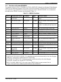
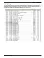
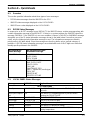
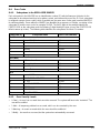
Revision History
The original issue and revisions of this Service Manual for the Kodak DryView 8150 LASER IMAGER are
identified as follows:
Issue date: 07/05
All pages are dated November, 2004 in the initial issue.
Section
Title
Text
Rev.
B
Pages Changed in Current
Revision*
--
Warnings
B
--
TOC
B
--
1
B
--
2
B
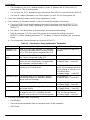
p4 added callout #10; p7 deleted fourth bullet and added a new bullet;
p15 added step #9; p26 added Configuring SCP and added a Note;
p32 revised Note text and deleted steps 2 -- 5; p38 added overview
and replaced screen image; p39 added step a; p40 replaced screen
image; p41 replaced screen image; p42 revised Note and added step
29; p43 moved Training Key Operators to after Editing Service History;
p44 deleted par 2--8.
3
B
4
B
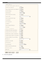
p1 revised temperature spec; p4 revised steps 3 and 6; p6 revised
screen image.
p1; p45 revised Caution.
5
B
p1 revised Note; p5 added procedure.
6
B
--
7
B
p3 added Problem, Cause, Remedy; p25 revised step; p31 added Reloading the MPDB; p70 added Using PCAnywhere; p71 revised heading to Using filtering and added Using Scripts.
8
B
p17 added 10.x.x.x Problem; p33 deleted Note; p35 revised step 7;
p50 added Other Possible Causes; p51 revised Summary; p63 added
Other Possible Causes and Film Pickup Suction Cup procedure; p69
added Other Possible Causes; p73 revised step 2; p81 added Other
Possible Causes; p82 added step #3; p87 revised procedure; p88 revised procedure; p90 deleted Note; p92 deleted Note; p94 revised step
1.
9
B
10
B
p3 revised part number #16; p8 added callout #20; p9 added item #20;
p10 ; p18 revised part number #6; p20 revised part number #13.
--
* New and revised text is marked by a change bar in the page margin.
Service Manual
Safety, Regulatory, EMC and CE Marking Compliance
All Installation and User--related safety information (Warnings and Cautions), regulatory, EMC and CE
marking information may be found in the Safety Manual for this device. Specific service--related warnings
and cautions are included in this manual.
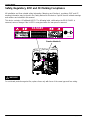
This device contains a 50 milliwatt LASER. The following label, visible when the REAR PANEL is
removed, warns of danger if the LASER is energized when the rear panel is removed.
D A NGER
Bypassing interlocks other than the
service interlock (above) will allow
system to run with laser energized!
Exposure to laser light may result
in permanent eye and skin damage!
96--0000--3663--0 C
Service Interlock
DANGER
96-- 0000-- 3663-- 0 B
!
WARNING
For continued protection against fire, replace fuses only with fuses of the same type and fuse rating.
ii
1584010 2005 July Rev. B
Table of Contents
PLEASE NOTE
The information contained herein is based on the experience and knowledge relating
to the subject matter gained by Eastman Kodak Company prior to publication.
No patent license is granted by this information.
Eastman Kodak Company reserves the right to change this information without notice
and makes no warranty, express or implied, with respect to this information. Kodak
shall not be liable for any loss or damage, including consequential or special
damages, resulting from the use of this information, even if loss or damage is caused
by Kodak’s negligence or other fault.
!
Caution
To avoid damage to ESD sensitive ELECTRONIC COMPONENTS, always wear an ANTI-STATIC
WRIST STRAP when handling CIRCUIT BOARDS or EPROMs.
Table of Contents
2005 July Rev. B
Revision History . . . . . . . . . . . . . . . . . . . . . . . . . . . . . . . . . . . . . . . . . . . . . . . .
i
Safety, Regulatory, EMC and CE Marking Compliance . . . . . . . . . . . . .
ii
Section 1 - Specifications . . . . . . . . . . . . . . . . . . . . . . . . . . . . . . . . . . . . . . .
1-1
1-1.
Dimensions . . . . . . . . . . . . . . . . . . . . . . . . . . . . . . . . . . . . . . . . . . . . . . . . . . . . .
1-1
1-2.
Electrical Power . . . . . . . . . . . . . . . . . . . . . . . . . . . . . . . . . . . . . . . . . . . . . . . . .
1-1
1-3.
Storage Environment . . . . . . . . . . . . . . . . . . . . . . . . . . . . . . . . . . . . . . . . . . . .
1-1
1-4.
Operating Environment . . . . . . . . . . . . . . . . . . . . . . . . . . . . . . . . . . . . . . . . . .
1-1
1-5.
Altitude . . . . . . . . . . . . . . . . . . . . . . . . . . . . . . . . . . . . . . . . . . . . . . . . . . . . . . . .
1-2
1-6.
Floor Vibration . . . . . . . . . . . . . . . . . . . . . . . . . . . . . . . . . . . . . . . . . . . . . . . . . .
1-2
1-7.
Floor Levelness . . . . . . . . . . . . . . . . . . . . . . . . . . . . . . . . . . . . . . . . . . . . . . . . .
1-2
1-8.
Floor Load . . . . . . . . . . . . . . . . . . . . . . . . . . . . . . . . . . . . . . . . . . . . . . . . . . . . . .
1-2
1-9.
Environmental Effects . . . . . . . . . . . . . . . . . . . . . . . . . . . . . . . . . . . . . . . . . . . .
1-2
1-10. Film Size . . . . . . . . . . . . . . . . . . . . . . . . . . . . . . . . . . . . . . . . . . . . . . . . . . . . . . .
1-2
1-11.
Film Throughput . . . . . . . . . . . . . . . . . . . . . . . . . . . . . . . . . . . . . . . . . . . . . . . . .
1-2
1-12. Image Input Options . . . . . . . . . . . . . . . . . . . . . . . . . . . . . . . . . . . . . . . . . . . . .
1-2
1-13. Glossary . . . . . . . . . . . . . . . . . . . . . . . . . . . . . . . . . . . . . . . . . . . . . . . . . . . . . . .
1-3
Section 2 -- Installation . . . . . . . . . . . . . . . . . . . . . . . . . . . . . . . . . . . . . . . . . .
2-1
2-1.
Checklist of Installation Procedures . . . . . . . . . . . . . . . . . . . . . . . . . . . . . . . .
2-1
2-2.
Tools Required for Installation . . . . . . . . . . . . . . . . . . . . . . . . . . . . . . . . . . . . .
2-1
2-3.
Uncrating and Initial Setup . . . . . . . . . . . . . . . . . . . . . . . . . . . . . . . . . . . . . . .
2-2
2-3-1.
2-3-2.
Opening the Shipping Crate . . . . . . . . . . . . . . . . . . . . . . . . . . . . . .
Completing the Uncrating . . . . . . . . . . . . . . . . . . . . . . . . . . . . . . . . .
2-2
2-3
2-3-3.
Removing the LASER IMAGER from the PALLET . . . . . . . . . . .
2-5
7F3318
iii
Service Manual
2-3-4.
2-3-5.
Checking the Accessory Materials . . . . . . . . . . . . . . . . . . . . . . . . .
Moving the IMAGER to the Installation Site . . . . . . . . . . . . . . . . .
2-7
2-8
2-3-6.
2-3-7.
Checking Site Readiness . . . . . . . . . . . . . . . . . . . . . . . . . . . . . . . . .
Required Configuration Information . . . . . . . . . . . . . . . . . . . . . . . .
2-9
2-9
Unpacking . . . . . . . . . . . . . . . . . . . . . . . . . . . . . . . . . . . . . . . . . . . . . . . . . . . . . .
2-4-1. Removing the Packing Materials from the Back of the IMAGER
2-11
2-11
2-4-2.
2-4-3.
Removing the Packing Materials from the Front of the IMAGER
Installing the CHARCOAL FILTER . . . . . . . . . . . . . . . . . . . . . . . . .
2-13
2-16
2-4-4.
Checking that Unpacking is Complete . . . . . . . . . . . . . . . . . . . . . .
2-17
Connecting to Electrical Power and the Network . . . . . . . . . . . . . . . . . . . .
2-5-1. Electrical Power Setup . . . . . . . . . . . . . . . . . . . . . . . . . . . . . . . . . . .
2-17
2-17
2-5-2.
Connecting to External AC Power . . . . . . . . . . . . . . . . . . . . . . . . .
2-19
2-5-3.
2-5-4.
2-5-5.
Connecting the IMAGER to the Network . . . . . . . . . . . . . . . . . . . .
Securing the IMAGER in its Operating Position . . . . . . . . . . . . . .
Applying Power . . . . . . . . . . . . . . . . . . . . . . . . . . . . . . . . . . . . . . . . .
2-20
2-20
2-21
2-6.
Configuring the IMAGER . . . . . . . . . . . . . . . . . . . . . . . . . . . . . . . . . . . . . . . . .
2-6-1. Setting the “Host Name” and the “IP Address” . . . . . . . . . . . . . . .
2-6-2. Checking the Port Number of the “Secure Tunnel” . . . . . . . . . . .
2-6-3. Setting the System Clock . . . . . . . . . . . . . . . . . . . . . . . . . . . . . . . . .
2-6-4. Checking the Values for “DICOM Source Communications” . . .
2-6-5. Setting up Service Tracking . . . . . . . . . . . . . . . . . . . . . . . . . . . . . . .
2-6-6. Configuring “SCP Services” . . . . . . . . . . . . . . . . . . . . . . . . . . . . . . .
2-6-7. Configuring the IMAGER to be a Destination . . . . . . . . . . . . . . . .
2-6-8. Configuring the LOCAL PANEL . . . . . . . . . . . . . . . . . . . . . . . . . . .
2-6-9. Selecting the Type of Film . . . . . . . . . . . . . . . . . . . . . . . . . . . . . . . .
2-6-10. Setting up Remote Monitoring (RMS) . . . . . . . . . . . . . . . . . . . . . .
2-6-11. RMS Grouping . . . . . . . . . . . . . . . . . . . . . . . . . . . . . . . . . . . . . . . . . .
2-21
2-22
2-23
2-24
2-25
2-26
2-26
2-33
2-36
2-38
2-39
2-40
2-7.
Checking Image Quality . . . . . . . . . . . . . . . . . . . . . . . . . . . . . . . . . . . . . . . . . .
2-43
2-8.
Backing up the System Configuration . . . . . . . . . . . . . . . . . . . . . . . . . . . . . .
2-44
2-9.
Training Key Operators . . . . . . . . . . . . . . . . . . . . . . . . . . . . . . . . . . . . . . . . . .
2-44
2--10
Editing the Service History Log . . . . . . . . . . . . . . . . . . . . . . . . . . . . . . . . . . . .
2-47
2-11.
Guidelines for Selecting the Correct TFT Set and Related Parameters .
2-12-1. Definitions . . . . . . . . . . . . . . . . . . . . . . . . . . . . . . . . . . . . . . . . . . . . . .
2-48
2-48
2-4.
2-5.
iv
2-12-2. Selecting the Image Quality Parameters Appropriate to the
MODALITY . . . . . . . . . . . . . . . . . . . . . . . . . . . . . . . . . . . . . . . . .
2-12-3. Selecting Parameters for MODALITIES that are not
DICOM-GSDF-Compliant . . . . . . . . . . . . . . . . . . . . . . . . . . . .
2-49
2-12-4. Selecting Parameters for DICOM GSDF-Compliant
MODALITIES . . . . . . . . . . . . . . . . . . . . . . . . . . . . . . . . . . . . . . .
2-49
2-12-5. TFT Set Descriptions . . . . . . . . . . . . . . . . . . . . . . . . . . . . . . . . . . . .
2-53
7F3318
2-48
2005 July Rev. B
Table of Contents
Section 3 - Adjustments . . . . . . . . . . . . . . . . . . . . . . . . . . . . . . . . . . . . . . . . .
3-1
3-1.
Setting Temperature of the PROCESSOR DRUM . . . . . . . . . . . . . . . . . . .
3-1
3-2.
Processor Drum RTD . . . . . . . . . . . . . . . . . . . . . . . . . . . . . . . . . . . . . . . . . . . .
3-4
3-3.
Processor Film Diverter Assembly (Stripper) . . . . . . . . . . . . . . . . . . . . . . . .
3-5
3-4.
Optics Translation Speed and SOP Delay . . . . . . . . . . . . . . . . . . . . . . . . . .
3-6
3-5.
Reference Level for DENSITOMETER . . . . . . . . . . . . . . . . . . . . . . . . . . . . .
3-8
3-6.
Dynamic Range of the LASER . . . . . . . . . . . . . . . . . . . . . . . . . . . . . . . . . . . .
3-10
3-7.
Optics Laser Power . . . . . . . . . . . . . . . . . . . . . . . . . . . . . . . . . . . . . . . . . . . . . .
3-12
Section 4 -- Disassembly/Reassembly . . . . . . . . . . . . . . . . . . . . . . . . . . . .
4-1
4-1.
Front Door and Rear Panel Assemblies . . . . . . . . . . . . . . . . . . . . . . . . . . . .
4-1-1. Front Door Filter . . . . . . . . . . . . . . . . . . . . . . . . . . . . . . . . . . . . . . . . .
4-1
4-1
4-1-2.
Rear Panel . . . . . . . . . . . . . . . . . . . . . . . . . . . . . . . . . . . . . . . . . . . . .
4-2
4-2.
Film Processor Assembly . . . . . . . . . . . . . . . . . . . . . . . . . . . . . . . . . . . . . . . . .
4-2-1. Processor Interface Board . . . . . . . . . . . . . . . . . . . . . . . . . . . . . . . .
4-2-2. Processor Drum . . . . . . . . . . . . . . . . . . . . . . . . . . . . . . . . . . . . . . . . .
4-2-3. Processor Rollers and Related Parts . . . . . . . . . . . . . . . . . . . . . . .
4-2-4. Processor Motor . . . . . . . . . . . . . . . . . . . . . . . . . . . . . . . . . . . . . . . . .
4-2-5. Kicker Motor . . . . . . . . . . . . . . . . . . . . . . . . . . . . . . . . . . . . . . . . . . . .
4-2-6. Processor Film Diverter Assembly . . . . . . . . . . . . . . . . . . . . . . . . .
4-3
4-3
4-4
4-6
4-7
4-9
4-11
4-3.
Roller Set Assemblies . . . . . . . . . . . . . . . . . . . . . . . . . . . . . . . . . . . . . . . . . . . .
4-12
4-4.
Densitometer Assembly . . . . . . . . . . . . . . . . . . . . . . . . . . . . . . . . . . . . . . . . . .
4-4-1. Densitometer Module . . . . . . . . . . . . . . . . . . . . . . . . . . . . . . . . . . . .
4-4-2. Densitometer/Exit Sensor (S9) . . . . . . . . . . . . . . . . . . . . . . . . . . . .
4-4-3. Densitometer Light Source Assembly . . . . . . . . . . . . . . . . . . . . . .
4-4-4. Densitometer Board . . . . . . . . . . . . . . . . . . . . . . . . . . . . . . . . . . . . .
4-14
4-14
4-15
4-16
4-17
4-5.
Local Panel Assembly . . . . . . . . . . . . . . . . . . . . . . . . . . . . . . . . . . . . . . . . . . .
4-18
4-6.
Film Pickup Assembly . . . . . . . . . . . . . . . . . . . . . . . . . . . . . . . . . . . . . . . . . . . .
4-6-1. Film Pickup Module . . . . . . . . . . . . . . . . . . . . . . . . . . . . . . . . . . . . . .
4-6-2. Film Pickup Cups . . . . . . . . . . . . . . . . . . . . . . . . . . . . . . . . . . . . . . . .
4-19
4-19
4-20
4-6-3.
Film Pickup Heel Pad . . . . . . . . . . . . . . . . . . . . . . . . . . . . . . . . . . . .
4-21
4-6-4.
4-6-5.
4-6-6.
Film Pickup Optical Sensors (S3, S4, S5, S10) . . . . . . . . . . . . . .
Film Pickup Motor (DCM2) . . . . . . . . . . . . . . . . . . . . . . . . . . . . . . . .
Film Pickup Vacuum Pump . . . . . . . . . . . . . . . . . . . . . . . . . . . . . . .
4-22
4-23
4-24
Rollback Assembly . . . . . . . . . . . . . . . . . . . . . . . . . . . . . . . . . . . . . . . . . . . . . .
4-25
4-7-1.
Rollback Module . . . . . . . . . . . . . . . . . . . . . . . . . . . . . . . . . . . . . . . .
4-25
4-7-2.
4-7-3.
4-7-4.
Rollback Motor (DCM1) . . . . . . . . . . . . . . . . . . . . . . . . . . . . . . . . . .
Cartridge Present Sensor (S1) . . . . . . . . . . . . . . . . . . . . . . . . . . . .
Rollback Home Sensor (S2) . . . . . . . . . . . . . . . . . . . . . . . . . . . . . .
4-27
4-28
4-29
4-7.
2005 July Rev. B
7F3318
v
Service Manual
4-7-5.
4-7-6.
4-7-7.
4-8.
Rollback Open Sensor (S13) . . . . . . . . . . . . . . . . . . . . . . . . . . . . . .
4-30
RF Tag Assembly (RF Tag interface Board and RF Reader Board) . . . . .
4-31
RF Antenna Board . . . . . . . . . . . . . . . . . . . . . . . . . . . . . . . . . . . . . . .
4-32
Elevator Assembly . . . . . . . . . . . . . . . . . . . . . . . . . . . . . . . . . . . . . . . . . . . . . . .
4-8-1. Elevator Module . . . . . . . . . . . . . . . . . . . . . . . . . . . . . . . . . . . . . . . . .
4-33
4-33
4-8-2.
4-8-3.
Elevator Home Sensor (S12) . . . . . . . . . . . . . . . . . . . . . . . . . . . . . .
Elevator Motor and Hub Assembly (Step 8) . . . . . . . . . . . . . . . . .
4-34
4-35
FEED ROLLER ASSEMBLY . . . . . . . . . . . . . . . . . . . . . . . . . . . . . . . . . . . . . .
4-9-1. FEED ROLLER MODULE . . . . . . . . . . . . . . . . . . . . . . . . . . . . . . . .
4-9-2. Feed Roller Open Sensor (S11) . . . . . . . . . . . . . . . . . . . . . . . . . . .
4-36
4-36
4-37
4-9-3.
Feed Roller Open Motor (DCM4) . . . . . . . . . . . . . . . . . . . . . . . . . .
4-38
4-9-4.
4-9-5.
Feed Roller Motor) and Pulley . . . . . . . . . . . . . . . . . . . . . . . . . . . . .
Feed Roller Torsion Springs . . . . . . . . . . . . . . . . . . . . . . . . . . . . . . .
4-40
4-41
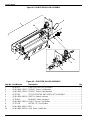
4-10. Vertical Transport ASSEMBLY . . . . . . . . . . . . . . . . . . . . . . . . . . . . . . . . . . . .
4-42
4-10-1. Vertical Transport MODULE . . . . . . . . . . . . . . . . . . . . . . . . . . . . . . .
4-10-2. Vertical Transport Sensor (S8) . . . . . . . . . . . . . . . . . . . . . . . . . . . .
4-10-3. VERTICAL TRANSPORT MOTOR (Step 6) . . . . . . . . . . . . . . . . .
4-42
4-43
4-44
4-9.
4-11.
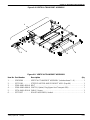
IMAGING (EXPOSURE) ASSEMBLY . . . . . . . . . . . . . . . . . . . . . . . . . . . . . .
4-45
4-11-1. IMAGING MODULE . . . . . . . . . . . . . . . . . . . . . . . . . . . . . . . . . . . . . .
4-45
4-11-2. SCANNER ASSEMBLY . . . . . . . . . . . . . . . . . . . . . . . . . . . . . . . . . .
4-46
4-11-3. PLATEN FILM SENSOR (S6) . . . . . . . . . . . . . . . . . . . . . . . . . . . . .
4-48
4-11-4. OPTICS HOME SENSOR (S7) . . . . . . . . . . . . . . . . . . . . . . . . . . . .
4-49
4-11-5. Optics Translation MOTOR (Step 4) and Capstan . . . . . . . . . . .
4-50
4-11-6. FILM CENTERING ASSEMBLY and CENTERING MOTOR (Step 7) . . .
4-51
4-11-7. PLATEN ROLLER MOTOR (Step 2) . . . . . . . . . . . . . . . . . . . . . . .
4-52
4-11-8. PLATEN NIP ROLLER BELT . . . . . . . . . . . . . . . . . . . . . . . . . . . . . .
4-53
4-11-9. PLATEN NIP and DRIVE ROLLERS . . . . . . . . . . . . . . . . . . . . . . .
4-11-10. VIBRATION MOUNTS . . . . . . . . . . . . . . . . . . . . . . . . . . . . . . . . . . .
4-11-11. OPTICS MODULE . . . . . . . . . . . . . . . . . . . . . . . . . . . . . . . . . . . . . . .
4-54
4-56
4-58
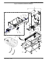
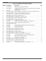
4-12. POWER ASSEMBLY . . . . . . . . . . . . . . . . . . . . . . . . . . . . . . . . . . . . . . . . . . . .
4-62
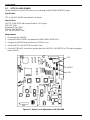
4-13. MCS ELECTRONIC COMPONENTS . . . . . . . . . . . . . . . . . . . . . . . . . . . . . .
4-63
4-14. DICOM RASTER ENGINE (DRE) COMPUTER . . . . . . . . . . . . . . . . . . . . .
4-14-1. DRE HARD DRIVE, CD-ROM DRIVE, or FLOPPY DRIVE . . . .
4-14-2. Removing the FLOPPY DRIVE . . . . . . . . . . . . . . . . . . . . . . . . . . . .
4-14-3. Removing the PCIO BOARD, Ethernet BOARD, or LOCAL PANEL
TRANSMITTER BOARD . . . . . . . . . . . . . . . . . . . . . . . . . . . . .
4-66
4-71
4-72
4-14-4. Removing the DIMM MEMORY BOARDS . . . . . . . . . . . . . . . . . .
4-14-5. Removing the DRE POWER SUPPLY . . . . . . . . . . . . . . . . . . . . . .
vi
7F3318
4-73
4-74
4-75
2005 July Rev. B
Table of Contents
Section 5 -- Tools/Preventive Maintenance/Cleaning . . . . . . . . . . . . . . .
5-1
5-1.
Required Tools . . . . . . . . . . . . . . . . . . . . . . . . . . . . . . . . . . . . . . . . . . . . . . . . . .
5-1
5-2.
TEMPERATURE METER and PROBE Calibration . . . . . . . . . . . . . . . . . . .
5-2
5-3.
Serial Number Location . . . . . . . . . . . . . . . . . . . . . . . . . . . . . . . . . . . . . . . . . .
5-2
5-4.
Preventive Maintenance . . . . . . . . . . . . . . . . . . . . . . . . . . . . . . . . . . . . . . . . . .
5-4-1. PM Intervals . . . . . . . . . . . . . . . . . . . . . . . . . . . . . . . . . . . . . . . . . . . .
5-4-2. Supplies Required for PM . . . . . . . . . . . . . . . . . . . . . . . . . . . . . . . .
5-3
5-3
5-3
5-4-3.
EM Call Checklist . . . . . . . . . . . . . . . . . . . . . . . . . . . . . . . . . . . . . . . .
5-4
5-4-4.
5-4-5.
5-4-6.
20,000 Cycle PM Checklist . . . . . . . . . . . . . . . . . . . . . . . . . . . . . . .
Cleaning the EXPOSURE PLATEN . . . . . . . . . . . . . . . . . . . . . . . .
Replacing the FRONT DOOR AIR FILTER . . . . . . . . . . . . . . . . . .
5-5
5-6
5-7
5-4-7.
5-4-8.
Replacing the CHARCOAL FILTER . . . . . . . . . . . . . . . . . . . . . . . .
Removing and Checking the PROCESSOR DRUM . . . . . . . . . .
5-10
5-11
5-4-9.
Cleaning the DRUM, HEAT SHIELD and PROCESSOR ROLLERS . . . .
5-13
5-4-10.
5-4-11.
5-4-12.
5-4-13.
Cleaning the FILM DIVERTER ASSEMBLY . . . . . . . . . . . . . . . . .
Replace the PROCESSOR GASKET . . . . . . . . . . . . . . . . . . . . . .
Installing the DRUM . . . . . . . . . . . . . . . . . . . . . . . . . . . . . . . . . . . . .
Completing the PM . . . . . . . . . . . . . . . . . . . . . . . . . . . . . . . . . . . . . .
5-15
5-17
5-17
5-19
Cleaning the OPTICS MODULE . . . . . . . . . . . . . . . . . . . . . . . . . . . . . . . . . . .
5-20
Section 6 - Theory of Operation . . . . . . . . . . . . . . . . . . . . . . . . . . . . . . . . . .
6-1
6-1.
General . . . . . . . . . . . . . . . . . . . . . . . . . . . . . . . . . . . . . . . . . . . . . . . . . . . . . . . .
6-1
6-2.
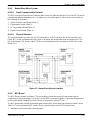
The DICOM RASTER ENGINE (DRE) . . . . . . . . . . . . . . . . . . . . . . . . . . . . .
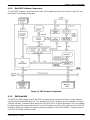
6-2-1. DRE Hardware . . . . . . . . . . . . . . . . . . . . . . . . . . . . . . . . . . . . . . . . . .
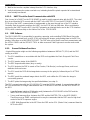
6-2-1-1. DRE Computer Hardware Components . . . . . . . . . . . .
6-2-1-2. LOCAL PANEL . . . . . . . . . . . . . . . . . . . . . . . . . . . . . . . . .
6-2-1-3. Image Processing in Main Memory . . . . . . . . . . . . . . . .
6-2-2. PCIO BOARD . . . . . . . . . . . . . . . . . . . . . . . . . . . . . . . . . . . . . . . . . . .
6-2-2-1. Digital Output Circuit . . . . . . . . . . . . . . . . . . . . . . . . . . . .
6-2-2-2. UART Circuit for Serial Communication with MCS . . .
6-2
6-2
6-2
6-3
6-4
6-4
6-5
6-6
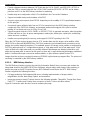
6-3.
DRE Software . . . . . . . . . . . . . . . . . . . . . . . . . . . . . . . . . . . . . . . . . . . . . . . . . .
6-6
5-5.
6-3-1.
6-3-2.
6-3-3.
6-3-4.
2005 July Rev. B
7F3318
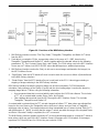
General Software Functions . . . . . . . . . . . . . . . . . . . . . . . . . . . . . .
Main DRE Software Components . . . . . . . . . . . . . . . . . . . . . . . . . .
PACSLink MIM . . . . . . . . . . . . . . . . . . . . . . . . . . . . . . . . . . . . . . . . . .
6-3-3-1. MIM Delivery Interface . . . . . . . . . . . . . . . . . . . . . . . . . . .
6-3-3-2. DICOM Modality Preferences Database (MPDB) . . . .
MCS Interface Server (MIS) . . . . . . . . . . . . . . . . . . . . . . . . . . . . . . .
6-3-4-1. General . . . . . . . . . . . . . . . . . . . . . . . . . . . . . . . . . . . . . . . .
6-3-4-2. MCS Image Server . . . . . . . . . . . . . . . . . . . . . . . . . . . . . .
6-3-4-3. MCS/MIS Command Server . . . . . . . . . . . . . . . . . . . . . .
6-3-4-4. Service Providers . . . . . . . . . . . . . . . . . . . . . . . . . . . . . . .
6-6
6-7
6-7
6-8
6-10
6-10
6-10
6-10
6-11
6-11
vii
Service Manual
6-4.
6-3-5.
6-3-6.
MCS Database Server . . . . . . . . . . . . . . . . . . . . . . . . . . . . . . . . . . .
Web Server . . . . . . . . . . . . . . . . . . . . . . . . . . . . . . . . . . . . . . . . . . . . .
6-11
6-11
6-3-7.
Browsers for SERVICE LAPTOP and LOCAL PANEL . . . . . . . .
6-3-7-1. Active Server Pages (ASP) for SERVICE LAPTOP
and LOCAL PANEL . . . . . . . . . . . . . . . . . . . . . . . . . . . . .
6-3-7-2. Data Formatters for Service Tool and LOCAL PANEL
6-11
6-11
6-11
Machine Control System (MCS) . . . . . . . . . . . . . . . . . . . . . . . . . . . . . . . . . . .
6-12
6-4-1.
Master/Slave Micro System . . . . . . . . . . . . . . . . . . . . . . . . . . . . . . .
6-4-1-1. Serial Communication Protocol . . . . . . . . . . . . . . . . . . .
6-4-1-2. Physical Interface . . . . . . . . . . . . . . . . . . . . . . . . . . . . . . .
MCS Board . . . . . . . . . . . . . . . . . . . . . . . . . . . . . . . . . . . . . . . . . . . . .
6-4-2-1. Master CPU . . . . . . . . . . . . . . . . . . . . . . . . . . . . . . . . . . . .
6-4-2-2. Film Processor Control . . . . . . . . . . . . . . . . . . . . . . . . . .
6-4-2-3. Stepper Motor Drive . . . . . . . . . . . . . . . . . . . . . . . . . . . . .
6-4-2-4. Media Lookup Table (Linear LUT) . . . . . . . . . . . . . . . . .
6-4-2-5. Laser Scanning Characteristics . . . . . . . . . . . . . . . . . . .
6-4-2-6. General Pixel Flow Control Functions . . . . . . . . . . . . . .
Laser Optics Subsystem . . . . . . . . . . . . . . . . . . . . . . . . . . . . . . . . . .
6-4-3-1. General . . . . . . . . . . . . . . . . . . . . . . . . . . . . . . . . . . . . . . . .
6-4-3-2. Film Platen . . . . . . . . . . . . . . . . . . . . . . . . . . . . . . . . . . . . .
6-4-3-3. Optics Module . . . . . . . . . . . . . . . . . . . . . . . . . . . . . . . . . .
6-4-3-4. Optics Translation Assembly . . . . . . . . . . . . . . . . . . . . .
6-4-3-5. Optics Module Control Board . . . . . . . . . . . . . . . . . . . . .
Densitometer Module . . . . . . . . . . . . . . . . . . . . . . . . . . . . . . . . . . . .
6-4-4-1. Step Wedge Calibration . . . . . . . . . . . . . . . . . . . . . . . . . .
6-4-4-2. Reading the Dpatch . . . . . . . . . . . . . . . . . . . . . . . . . . . . .
6-4-4-3. Using Test Calibration Data to Create the Film Model
6-4-4-4. Densitometer Control Functions . . . . . . . . . . . . . . . . . . .
RF TAG SUBSYSTEMS . . . . . . . . . . . . . . . . . . . . . . . . . . . . . . . . . .
6-4-5-1. RF TAG SUBSYSTEM COMPONENTS . . . . . . . . . . . .
6-4-5-2. RF TAG Commands . . . . . . . . . . . . . . . . . . . . . . . . . . . . .
Feeder Control Board . . . . . . . . . . . . . . . . . . . . . . . . . . . . . . . . . . . .
6-4-6-1. Motor Control . . . . . . . . . . . . . . . . . . . . . . . . . . . . . . . . . . .
6-4-6-2. Sensor Control . . . . . . . . . . . . . . . . . . . . . . . . . . . . . . . . .
6-4-6-3. Film Pickup and Feed Functions . . . . . . . . . . . . . . . . . .
6-4-6-4. Cartridge Elevator Functions . . . . . . . . . . . . . . . . . . . . .
6-4-6-5. Cartridge Rollback Functions . . . . . . . . . . . . . . . . . . . . .
Processor Interface Board . . . . . . . . . . . . . . . . . . . . . . . . . . . . . . . .
DC Power Supply . . . . . . . . . . . . . . . . . . . . . . . . . . . . . . . . . . . . . . .
6-13
6-13
6-13
6-13
6-14
6-15
6-15
6-16
6-16
6-16
6-17
6-17
6-18
6-18
6-20
6-21
6-23
6-23
6-25
6-25
6-26
6-26
6-27
6-27
6-28
6-28
6-29
6-29
6-30
6-31
6-31
6-32
6-4-9. MCS Print Sequence of Operation . . . . . . . . . . . . . . . . . . . . . . . . .
6-4-10. Special Service Mode Operations . . . . . . . . . . . . . . . . . . . . . . . . .
6-32
6-47
AIQC and GSM . . . . . . . . . . . . . . . . . . . . . . . . . . . . . . . . . . . . . . . . . . . . . . . . .
6-47
6-5-1.
6-5-2.
Purpose of AIQC . . . . . . . . . . . . . . . . . . . . . . . . . . . . . . . . . . . . . . . .
Purpose of GSM . . . . . . . . . . . . . . . . . . . . . . . . . . . . . . . . . . . . . . . .
6-47
6-47
6-5-3.
Power up, Calibration, and Print Sequence . . . . . . . . . . . . . . . . .
6-49
6-4-2.
6-4-3.
6-4-4.
6-4-5.
6-4-6.
6-4-7.
6-4-8.
6-5.
viii
7F3318
2005 July Rev. B
Table of Contents
Section 7 - Troubleshooting . . . . . . . . . . . . . . . . . . . . . . . . . . . . . . . . . . . . .
7-1
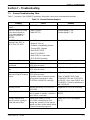
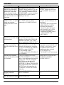
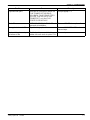
7-1.
General Troubleshooting Table . . . . . . . . . . . . . . . . . . . . . . . . . . . . . . . . . . . .
7-1
7-2.
Using the Service Tool (Service WebLink) . . . . . . . . . . . . . . . . . . . . . . . . . .
7-2-1. Setting Active Controls . . . . . . . . . . . . . . . . . . . . . . . . . . . . . . . . . . .
7-2-2. Network Settings for Service WebLink . . . . . . . . . . . . . . . . . . . . . .
7-2-3. Accessing the SERVICE TOOL . . . . . . . . . . . . . . . . . . . . . . . . . . .
7-3
7-4
7-5
7-6
7-2-4.
Testing the DENSITOMETER . . . . . . . . . . . . . . . . . . . . . . . . . . . . .
7-7
7-2-5.
7-2-6.
7-2-7.
Running the FRU Diagnostics . . . . . . . . . . . . . . . . . . . . . . . . . . . . .
Running the Mechanical Diagnostics . . . . . . . . . . . . . . . . . . . . . . .
Running Tests of the OPTICS . . . . . . . . . . . . . . . . . . . . . . . . . . . . .
7-8
7-9
7-12
7-2-8.
7-2-9.
Testing the SENSORS . . . . . . . . . . . . . . . . . . . . . . . . . . . . . . . . . . .
Obtaining Film Data . . . . . . . . . . . . . . . . . . . . . . . . . . . . . . . . . . . . . .
7-15
7-17
7-2-10. Obtaining Dpatch Data . . . . . . . . . . . . . . . . . . . . . . . . . . . . . . . . . . .
7-2-11. Plotting Film Calibration Data . . . . . . . . . . . . . . . . . . . . . . . . . . . . .
7-18
7-19
7-2-12. Testing the LOCAL PANEL . . . . . . . . . . . . . . . . . . . . . . . . . . . . . . .
7-2-13. Running a DRE Test Print . . . . . . . . . . . . . . . . . . . . . . . . . . . . . . . .
7-20
7-20
7-2-14.
7-2-15.
7-2-16.
7-2-17.
7-2-18.
7-2-19.
7-2-20.
7--2--21
Running an MCS Transport Test . . . . . . . . . . . . . . . . . . . . . . . . . . .
Obtaining a Diagnostics Summary . . . . . . . . . . . . . . . . . . . . . . . . .
Testing Communication on the Network . . . . . . . . . . . . . . . . . . . .
Troubleshooting the Source of Image Problems . . . . . . . . . . . . .
Configuration Backup . . . . . . . . . . . . . . . . . . . . . . . . . . . . . . . . . . . .
Configuration Restore . . . . . . . . . . . . . . . . . . . . . . . . . . . . . . . . . . . .
Upgrading the DRE Software -- “Ghosting” . . . . . . . . . . . . . . . . . .
Reloading the MPDB through RMS . . . . . . . . . . . . . . . . . . . . . . . .
7-21
7-21
7-23
7-24
7-28
7-29
7-30
7-31
7-3.
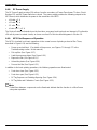
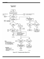
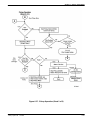
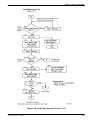
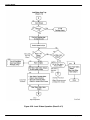
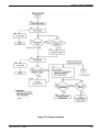
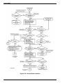
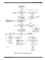
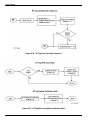
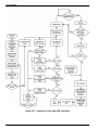
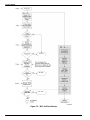
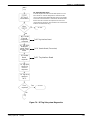
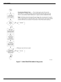
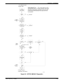
Using Power-On Self-Test as a Troubleshooting Tool . . . . . . . . . . . . . . . .
7-3-1. Setting up for Observation of Self-Test . . . . . . . . . . . . . . . . . . . . .
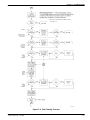
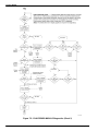
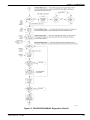
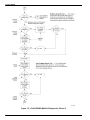
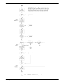
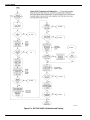
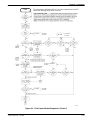
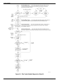
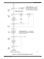
7-3-2. Initialization and Self-Test Sequence Flow Charts . . . . . . . . . . . .
7-33
7-33
7-33
7-4.
Functions of System SENSORS . . . . . . . . . . . . . . . . . . . . . . . . . . . . . . . . . . .
7-4-1. Testing the SENSORS Using LEDs . . . . . . . . . . . . . . . . . . . . . . . .
7-4-1-1. Testing Film Feed SENSORS S1-S5 and S10-S12
Via LEDs . . . . . . . . . . . . . . . . . . . . . . . . . . . . . . . . . . . . . . .
7-4-1-2. Testing ROLLBACK COMPLETE SENSOR S13
with LEDs . . . . . . . . . . . . . . . . . . . . . . . . . . . . . . . . . . . . . .
7-4-1-3. Testing SENSORS S6-S9 Via LEDs . . . . . . . . . . . . . . .
7-43
7-44
7-45
7-47
Troubleshooting Film Transport Problems . . . . . . . . . . . . . . . . . . . . . . . . . .
7-48
7-5-1.
7-5-2.
7-5-3.
Troubleshooting Basics . . . . . . . . . . . . . . . . . . . . . . . . . . . . . . . . . .
Troubleshooting Sequence . . . . . . . . . . . . . . . . . . . . . . . . . . . . . . .
Interviewing the Operator . . . . . . . . . . . . . . . . . . . . . . . . . . . . . . . . .
7-48
7-49
7-49
7-5-4.
Preliminary Visual Inspection . . . . . . . . . . . . . . . . . . . . . . . . . . . . . .
7-5-4-1. Preparation . . . . . . . . . . . . . . . . . . . . . . . . . . . . . . . . . . . .
7-5-4-2. Checking the ROLLBACK MODULE for Problems . . .
7-5-4-3. Checking the FILM PICKUP MODULE for Problems .
7-49
7-49
7-50
7-51
7-5.
2005 July Rev. B
7F3318
7-45
ix
Service Manual
7-5-5.
7-5-6.
7-5-7.
7-6.
Cycling Film and Observing the Film Transport Process . . . . . .
7-51
7-5-5-1. Preliminary Setup . . . . . . . . . . . . . . . . . . . . . . . . . . . . . . .
7-51
7-5-5-2. Checking the ROLLBACK MODULE . . . . . . . . . . . . . . .
7-52
7-5-5-3. Checking the FILM PICKUP MODULE . . . . . . . . . . . . .
7-52
7-5-5-4. Checking the FEED ROLLER MODULE . . . . . . . . . . .
7-53
7-5-5-5. Checking the PLATEN MODULE . . . . . . . . . . . . . . . . . .
7-53
Remove and Inspect Suspect MODULES . . . . . . . . . . . . . . . . . .
7-54
7-5-6-1. Removing and Inspecting the ROLLBACK MODULE
7-54
7-5-6-2. Removing and Inspecting the FILM PICKUP MODULE 7-55
7-5-6-3. Removing and Inspecting the FEED ROLLER MODULE . . . . .
7-60
7-5-6-4. Removing and Inspecting the FILM PLATEN MODULE 7-60
Replace the Repaired MODULE and Cycle Film to Confirm Repair . . . . .
7-61
Troubleshooting the Sources of Film Scratches . . . . . . . . . . . . . . . . . . . . .
7-6-1. Preparation for Transporting Film in the Service Mode . . . . . . . .
7-62
7-62
7-6-2.
7-6-3.
7-62
Isolating the General Area where Scratches are Occurring . . . .
Locating the Cause of Scratching in the
PROCESSOR/DENSITOMETER Area . . . . . . . . . . . . . . . . .
Locating the Cause of Scratching in the FILM PLATEN . . . . . . .
Guidelines for Removing the Causes of Scratches . . . . . . . . . . .
7-64
7-65
7-65
7-7.
Monitoring the MCS Via a Direct CABLE Connection to the
MCS BOARD . . . . . . . . . . . . . . . . . . . . . . . . . . . . . . . . . . . . . . . . . . . . . . . . . . .
7-66
7-8.
Using PCAnywhere. . . . . . . . . . . . . . . . . . . . . . . . . . . . . . . . . . . . . . . . . . . . 7--69
7--9.
Using Scipts. . . . . . . . . . . . . . . . . . . . . . . . . . . . . . . . . . . . . . . . . . . . . . . . . .7--70
7-6-4.
7-6-5.
7--10. Using the Logs . . . . . . . . . . . . . . . . . . . . . . . . . . . . . . . . . . . . . . . . . . . . . . . . . .
7-8-1. Types of Log . . . . . . . . . . . . . . . . . . . . . . . . . . . . . . . . . . . . . . . . . . . .
7-8-2. The Application Log . . . . . . . . . . . . . . . . . . . . . . . . . . . . . . . . . . . . .
7-8-2-1. Using the Application Log . . . . . . . . . . . . . . . . . . . . . . . .
7-8-2-2. Log Keying Functions . . . . . . . . . . . . . . . . . . . . . . . . . . .
7-8-2-3. Using Advanced filtering . . . . . . . . . . . . . . . . . . . . . . . . .
7-8-2-4. Contents of the Log . . . . . . . . . . . . . . . . . . . . . . . . . . . . .
7-8-2-5. Log Levels . . . . . . . . . . . . . . . . . . . . . . . . . . . . . . . . . . . . .
7-8-3. DICOM Log . . . . . . . . . . . . . . . . . . . . . . . . . . . . . . . . . . . . . . . . . . . . .
x
7-71
7-71
7-71
7-71
7-73
7-76
7-79
7-81
7-82
7-8-4.
7-8-5.
Error Tally . . . . . . . . . . . . . . . . . . . . . . . . . . . . . . . . . . . . . . . . . . . . . .
IIS Log . . . . . . . . . . . . . . . . . . . . . . . . . . . . . . . . . . . . . . . . . . . . . . . . .
7-83
7-85
7-8-6.
7-8-7.
Local Panel Log . . . . . . . . . . . . . . . . . . . . . . . . . . . . . . . . . . . . . . . . .
MCS Log . . . . . . . . . . . . . . . . . . . . . . . . . . . . . . . . . . . . . . . . . . . . . . .
7-86
7-87
7-8-8.
7-8-9.
NT Event Log (App) . . . . . . . . . . . . . . . . . . . . . . . . . . . . . . . . . . . . . .
NT Event Log (System) . . . . . . . . . . . . . . . . . . . . . . . . . . . . . . . . . .
7-88
7-89
7-8-10. Print Delivery Log . . . . . . . . . . . . . . . . . . . . . . . . . . . . . . . . . . . . . . .
7-90
Section 8 -- QuickSheets . . . . . . . . . . . . . . . . . . . . . . . . . . . . . . . . . . . . . . . . .
8-1
8-1.
8-1
Overview . . . . . . . . . . . . . . . . . . . . . . . . . . . . . . . . . . . . . . . . . . . . . . . . . . . . . . .
7F3318
2005 July Rev. B
Table of Contents
8-2.
DICOM Status Messages . . . . . . . . . . . . . . . . . . . . . . . . . . . . . . . . . . . . . . . .
8-1
8-3.
LOCAL PANEL Status Messages . . . . . . . . . . . . . . . . . . . . . . . . . . . . . . . . .
8-1
8-4.
Error Codes . . . . . . . . . . . . . . . . . . . . . . . . . . . . . . . . . . . . . . . . . . . . . . . . . . . .
8-4-1. Subsystems in the 8150 LASER IMAGER . . . . . . . . . . . . . . . . . .
8-3
8-3
8-4-2.
Error Severity Levels . . . . . . . . . . . . . . . . . . . . . . . . . . . . . . . . . . . . .
8-3
Error Code QuickSheets . . . . . . . . . . . . . . . . . . . . . . . . . . . . . . . . . . . . . . . . .
8-4
8-5.
8-5-1.
Error 00-099 through 00-530: Error Notification in General PACS
Subsystem . . . . . . . . . . . . . . . . . . . . . . . . . . . . . . . . . . . . . . . . .
8-4
8-5-2.
Error 01-001 through 01-910: Error Notification in Service
Subsystem . . . . . . . . . . . . . . . . . . . . . . . . . . . . . . . . . . . . . . . . .
Error 03-111: Rendering Error in Delivery Subsystem . . . . . . . .
8-5
8-6
8-5-3.
8-5-4.
8-5-5.
8-5-6.
8-5-7.
8-5-8.
8-5-9.
8-5-10.
8-5-11.
8-5-12.
8-5-13.
8-5-14.
8-5-15.
8--5--16
2005 July Rev. B
7F3318
Error 03-381 through 03--912: Error Notification in Routing/Delivery
Subsystem . . . . . . . . . . . . . . . . . . . . . . . . . . . . . . . . . . . . . . . . .
8-7
Error 03-650: Delivery Error Notification in Routing/Delivery
Subsystem . . . . . . . . . . . . . . . . . . . . . . . . . . . . . . . . . . . . . . . . .
8-8
Error 04-004 through 04--215: Error Notification in DICOM/Network
Subsystem . . . . . . . . . . . . . . . . . . . . . . . . . . . . . . . . . . . . . . . . .
8-9
Error 04-201: Maximum Number of DICOM Associations has been
Exceeded . . . . . . . . . . . . . . . . . . . . . . . . . . . . . . . . . . . . . . . . . .
8-10
Error 04-205: Resource Limitation Error in Network Subsystem
8-11
Error 05-000: Error in Storage Subsystem . . . . . . . . . . . . . . . . . .
8-12
Error 05-039: Unable to Reach Low Watermark . . . . . . . . . . . . .
8-13
Error 05-044: Low Watermark Has Been Reached . . . . . . . . . . .
8-14
Error 10-001: Delivery Subsystem Internal Software Error . . . .
8-15
Error 10-003: Image Datapath Error in Delivery Server
Subsystem . . . . . . . . . . . . . . . . . . . . . . . . . . . . . . . . . . . . . . . . .
8-16
10-910: No Communication with the MCS . . . . . . . . . . . . . . . . . .
8-17
10.x.x.x Problem. . . . . . . . . . . . . . . . . . . . . . . . . . . . . . . . . . . . . . . 8--17
Error 12-001: Software Error in LOCAL PANEL . . . . . . . . . . . . . .
8-19
8-5-17. Error 12-002: Database Error in LOCAL PANEL . . . . . . . . . . . . .
8-5-18. Error 12-003: Internal Software Error in LOCAL PANEL . . . . . .
8-5-19. Error 12-075: Error in LOCAL PANEL Software . . . . . . . . . . . . . .
8-20
8-21
8-22
8-5-20. Error 13-001: Error in SERVICE TOOL Software . . . . . . . . . . . .
8-5-21. Error 13-002: Database Error in SERVICE TOOL Software . . .
8-23
8-24
8-5-22. Error 13-003: SERVICE TOOL Script Error . . . . . . . . . . . . . . . . .
8-5-23. 20-137: Open DOOR Requested . . . . . . . . . . . . . . . . . . . . . . . . . .
8-5-24. 20-202: SERVICE OVERRIDE SWITCH Out . . . . . . . . . . . . . . . .
8-25
8-26
8-27
8-5-25. 20-208: DOOR Fail Open . . . . . . . . . . . . . . . . . . . . . . . . . . . . . . . . .
8-5-26. 20-550: Preventive Maintenance is Recommended . . . . . . . . . .
8-28
8-29
8-5-27. 20-912: Image Data Transfer Parity Error Detected . . . . . . . . . .
8-5-28. 20-913: Data Transfer Count Error Detected . . . . . . . . . . . . . . . .
8-30
8-31
xi
Service Manual
xii
8-5-29. Error 21-114: Film Pickup Failure before Opening or Closing
a CARTRIDGE . . . . . . . . . . . . . . . . . . . . . . . . . . . . . . . . . . . . .
8-32
8-5-30. Error 21-115: Film Pickup Retry Notification . . . . . . . . . . . . . . . .
8-5-31. Error 21-116: Film Pickup Failure . . . . . . . . . . . . . . . . . . . . . . . . . .
8-33
8-34
8-5-32. Error 21-117: FILM FEED ROLLERS Failed to Close . . . . . . . . .
8-5-33. Error 21-118: Pickup Failed to go Home . . . . . . . . . . . . . . . . . . . .
8-35
8-36
8-5-34. Error 21-119: Pickup Did Not Contact Film . . . . . . . . . . . . . . . . . .
8-5-35. Error 21-120: VACUUM CUPS Did Not Engage Film . . . . . . . . .
8-37
8-38
8-5-36. Error 21-131: ELEVATOR Failure . . . . . . . . . . . . . . . . . . . . . . . . . .
8-5-37. 21-132: No Supply CARTRIDGE . . . . . . . . . . . . . . . . . . . . . . . . . .
8-5-38. 21-134: Supply CARTRIDGE Empty . . . . . . . . . . . . . . . . . . . . . . .
8-39
8-40
8-41
8-5-39. 21-138: User Intervention Required to Open DOOR . . . . . . . . .
8-5-40. 21-139: Bad CARTRIDGE ID . . . . . . . . . . . . . . . . . . . . . . . . . . . . .
8-42
8-43
8-5-41. 21-145: Unsupported Media Type . . . . . . . . . . . . . . . . . . . . . . . . .
8-5-42. 21-146: Wrong Media Size . . . . . . . . . . . . . . . . . . . . . . . . . . . . . . . .
8-44
8-45
8-5-43.
8-5-44.
8-5-45.
8-5-46.
8-5-47.
8-5-48.
8-5-49.
8-5-50.
8-5-51.
8-5-52.
8-5-53.
8-5-54.
8-5-55.
8-5-56.
21-175: ROLLBACK Failed to Engage CARTRIDGE . . . . . . . .
21-176: Supply CARTRIDGE Could Not Be Fully Opened . . . .
21-177: Supply CARTRIDGE Could Not Be Closed . . . . . . . . . .
21-178: ROLLBACK Failed to Leave Home . . . . . . . . . . . . . . . . .
21-179: ROLLBACK Failed to Move from Open Position . . . . . .
21-515: Calibration Print Failed . . . . . . . . . . . . . . . . . . . . . . . . . . . .
21-624: Bad DENSITOMETER Data . . . . . . . . . . . . . . . . . . . . . . .
21-631: Dmin Not Met . . . . . . . . . . . . . . . . . . . . . . . . . . . . . . . . . . . .
21-632: Dmax Not Met . . . . . . . . . . . . . . . . . . . . . . . . . . . . . . . . . . .
21-921: FEEDER Diagnostics Failure . . . . . . . . . . . . . . . . . . . . . .
25-922: RF TAG SUBSYSTEM Diagnostics Failure . . . . . . . . . .
25-931: RF TAG SUBSYSTEM Communications Failure . . . . . .
25-932: RF TAG SUBSYSTEM Communications Retry . . . . . . .
26-163: Jam Loading Exposure PLATEN . . . . . . . . . . . . . . . . . . .
8-46
8-47
8-48
8-49
8-50
8-51
8-52
8-53
8-54
8-55
8-60
8-61
8-62
8-63
8-5-57. 26-164: Jam Loading Exposure PLATEN . . . . . . . . . . . . . . . . . . .
8-5-58. 26-165: Jam at TRANSPORT . . . . . . . . . . . . . . . . . . . . . . . . . . . . .
8-5-59. Error 26-166: Film Jam at VERTICAL TRANSPORT . . . . . . . . .
8-64
8-65
8-66
8-5-60. 26-169: Jam Unloading Exposure PLATEN . . . . . . . . . . . . . . . . .
8-5-61. 26-542: Jam at PROCESSOR . . . . . . . . . . . . . . . . . . . . . . . . . . . .
8-67
8-68
8-5-62.
8-5-63.
8-5-64.
8-5-65.
26-543: Jam Prior to DENSITOMETER . . . . . . . . . . . . . . . . . . . . .
26-544: Jam at DENSITOMETER . . . . . . . . . . . . . . . . . . . . . . . . .
Error 27-121: ATTENUATOR Error . . . . . . . . . . . . . . . . . . . . . . . . .
27-123: SPINNER Error . . . . . . . . . . . . . . . . . . . . . . . . . . . . . . . . . .
8-69
8-70
8-71
8-72
8-5-66. 27-602: Invalid POWER MONITOR Range with ATTENUATOR
Open . . . . . . . . . . . . . . . . . . . . . . . . . . . . . . . . . . . . . . . . . . . . . .
8-5-67. 27-603: Invalid ATTENUATOR Optical Density Range . . . . . . . .
8-73
8-75
8-5-68. 27-604: Invalid Laser Dynamic Range . . . . . . . . . . . . . . . . . . . . . .
8-77
7F3318
2005 July Rev. B
Table of Contents
2005 July Rev. B
8-5-69. 27-605: POWER MONITOR is Saturated . . . . . . . . . . . . . . . . . . .
8-5-70. 27-606: ATTENUATOR Calibration Failed . . . . . . . . . . . . . . . . . .
8-79
8-80
8-5-71. 27-640: Optics Translation Home Failure . . . . . . . . . . . . . . . . . . .
8-5-72. 27-641: Optics NVRAM Failure . . . . . . . . . . . . . . . . . . . . . . . . . . . .
8-81
8-82
8-5-73. 27-923: Optics Diagnostics Failed . . . . . . . . . . . . . . . . . . . . . . . . .
8-5-74. 27-931: Optics Communications Failed . . . . . . . . . . . . . . . . . . . . .
8-83
8-85
8-5-75. 27-932: Optics Communications Retry . . . . . . . . . . . . . . . . . . . . .
8-5-76. 28-506: MCS Cannot Read PROCESSOR Temperature . . . . . .
8-86
8-87
8-5-77. 28-509: PROCESSOR Warmup Failure . . . . . . . . . . . . . . . . . . . .
8-5-78. 28-551: PROCESSOR DRUM HEATER Failure . . . . . . . . . . . . .
8-5-79. 28-554: PROCESSOR Over Temperature Error . . . . . . . . . . . . .
8-88
8-90
8-92
8-5-80. 29-924: DENSITOMETER Offset Failure with Light Source Off
8-94
8-5-81. 29-925: DENSITOMETER Offset Failure with Light Source On
8-5-82. 29-931: MCS Cannot Communicate with DENSITOMETER . . .
8-5-83. 29-932: MCS Cannot Communicate with DENSITOMETER
Notification . . . . . . . . . . . . . . . . . . . . . . . . . . . . . . . . . . . . . . . . .
8-96
8-97
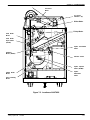
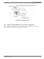
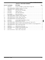
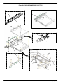
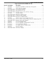
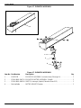
Section 9 - Illustrated Parts Breakdown . . . . . . . . . . . . . . . . . . . . . . . . . .
9-1
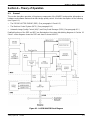
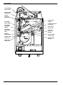
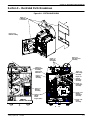
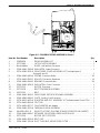
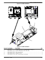
Figure 9-0. SYSTEM OVERVIEW . . . . . . . . . . . . . . . . . . . . . . . . . . . . . . . . .
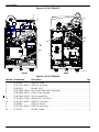
Figure 9-1. CABINETRY WITH LOCAL PANEL . . . . . . . . . . . . . . . . . . . . . .
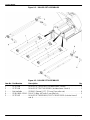
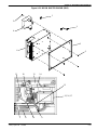
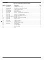
Figure 9-2. FILM PROCESSOR ASSEMBLY . . . . . . . . . . . . . . . . . . . . . . .
Figure 9-3. ROLLER SET ASSEMBLIES . . . . . . . . . . . . . . . . . . . . . . . . . .
Figure 9-4. DENSITOMETER ASSEMBLY . . . . . . . . . . . . . . . . . . . . . . . . .
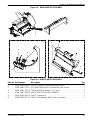
Figure 9-5. FILM PICKUP ASSEMBLY . . . . . . . . . . . . . . . . . . . . . . . . . . . . .
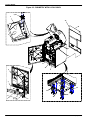
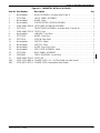
Figure 9-6. ROLLBACK ASSEMBLY, RF TAG . . . . . . . . . . . . . . . . . . . . . . .
Figure 9-7. ELEVATOR ASSEMBLY . . . . . . . . . . . . . . . . . . . . . . . . . . . . . . .
9-1
9-2
9-4
9-6
9-7
9-8
9-10
9-12
Figure 9-8. VERTICAL TRANSPORT ASSEMBLY . . . . . . . . . . . . . . . . . . .
Figure 9-9. FILM FEED ROLLER ASSEMBLY . . . . . . . . . . . . . . . . . . . . . .
9-13
9-14
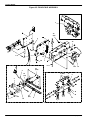
Figure 9-10. IMAGING (EXPOSURE) ASSEMBLY . . . . . . . . . . . . . . . . . . .
Figure 9-11. POWER ASSEMBLY . . . . . . . . . . . . . . . . . . . . . . . . . . . . . . . . .
Figure 9-12. ELECTRONICS . . . . . . . . . . . . . . . . . . . . . . . . . . . . . . . . . . . . .
9-15
9-17
9-18
Figure 9-13. DICOM RASTER ENGINE (DRE) . . . . . . . . . . . . . . . . . . . . .
Figure 9-14. INTERNAL CABLING . . . . . . . . . . . . . . . . . . . . . . . . . . . . . . . .
9-19
9-21
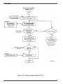
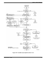
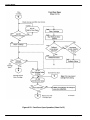
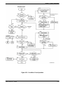
Section 10 - Diagrams . . . . . . . . . . . . . . . . . . . . . . . . . . . . . . . . . . . . . . . . . . .
10-1
10-1. System Functional Diagrams . . . . . . . . . . . . . . . . . . . . . . . . . . . . . . . . . . . . .
10-1
7F3318
8-98
xiii
Section 1 -- Specifications
Section 1 -- Specifications
1-1.
Dimensions
Unpacked:
Height:
116.8 cm (46 in.) -- Top Cover closed
158.1 cm (62-1/4 in.) -- Top Cover open
Width:
63.5 cm (25 in.)
Depth:
66.0 cm (26 in.) -- Front Door closed
124.5 cm (49 in.) -- Front Door open
Weight:
204 kg (450 lbs)
Packed:
Height:
145 cm (57 in.)
Width:
81 cm (32 in.)
Depth:
99 cm (39 in.)
Weight:
268 kg (590 lbs)
1-2.
Electrical Power
Line-matching is accomplished by the use of VOLTAGE SELECTION PLUGS inserted at the primary of
the POWER TRANSFORMER.
Input Voltage:
•
100 VAC ± 10%, 50/60 ± 3 Hz
•
120 VAC ± 10%. 60 ± 3 Hz
•
230 VAC ± 10%, 50 ± 3 Hz
Input Current Draw:
•
Less than 12 Amps at 100 VAC input voltage
•
Less than 10 Amps at 120 VAC input voltage
•
Less than 5.3 Amps at 230 VAC input voltage
Power Consumption: 700 watts maximum
1-3.
Storage Environment
Temperature:
--35° to 60°C (--31° to 140°F)
Humidity:
10% to 90% RH, Noncondensing
1-4.
Operating Environment
Temperature:
15° to 35°C (59° to 95°F)
Humidity:
15% to 85% RH, Noncondensing
Magnetic Field:
50 Gauss (maximum)
2005 July Rev. B
7F3318
1-1
Service Manual
1-5.
Altitude
--30.5 m (100 ft) below sea level to 3,050 m (10,000 ft) above sea level
1-6.
Floor Vibration
The IMAGER shall operate with no image degradation with floor vibration levels up to:
•
1 x 10 -- & G2/Hz at a frequency range of 1--50 Hz in the vertical or horizontal direction
•
6 x 10 --5 G2/Hz at a frequency range of 50--200 Hz in the vertical or horizontal direction
•
5 x 10 --6 G2/Hz at a frequency range of 200--650 Hz in the vertical or horizontal direction
•
1 x 10 --6 G2/Hz at a frequency range of 650--1000 Hz in the vertical or horizontal direction
1-7.
Floor Levelness
The floor must be level within 1° with respect to gravity vector direction.
1-8.
Floor Load
100 lb/sq in. , calculated by dividing machine weight by machine floor “foot print” (450 lb/4.5 sq ft).
1-9.
Environmental Effects
Heat Dissipation:
3000 BTU/Hr (average)
Acoustical Noise:
Less than 55 dB-A at 1 meter (less than 70 dB momentarily)
Less than 80 dB-A at 1 meter for non-repetitive tasks such as door open/close
1-10. Film Size
The Kodak DryView 8150 LASER IMAGER will process Kodak DryView LASER IMAGING FILM in the
following sizes:
•
35 x 43 cm
•
35 x 35 cm
•
11 x 14 in.
1-11. Film Throughput
Up to 70 films per hour
1-12. Image Input Options
DICOM Network Interface
1-2
7F3318
2005 July Rev. B
Section 1 -- Specifications
1-13. Glossary
Following are definitions of abbreviations and technical terms used in this manual.
ACK
Acknowledge -- A hardware signal (response) that indicates reception of a signal.
A/D
Analog to Digital -- The conversion of an analog signal to digital format.
ADC
Analog to Digital Converter -- The hardware circuit that converts analog to digital format.
AIQC
Automatic Image Quality Control -- The subsystem in the laser imager consisting of
hardware and software that ensures consistent image quality.
API
Application Programming Interface -- The Library and Tools software that handles
video parameters, and mediates differences between CHP file parameters and MIB video
variables.
BOM
Beginning of Message
Browser
A computer program that accesses and displays information from the web. It contains
multiple application programs, and uses an object’s name (URL) to determine which
application should be used to access the object.
Carrier Profile A term categorizing a subset of video parameters that describe the video signal itself as
opposed to the image content carried on the video signal.
CGI
Common Gateway Interface
COM
Communications (Port)
CPU
Central Processing Unit -- The microprocessing chip in a computer.
DAC
Digital to Analog Converter
DICOM
Digital Imaging and Communications in Medicine
DLogE
Density versus the Log of Exposure
DMA
Direct Memory Access
Dmax
Maximum Density -- Greatest possible image density, i.e., the density of the black step of
the gray scale.
Dmin
Minimum Density -- The measured density of film base plus fog. (Can be referenced either
to the film or the image.)
Dpatch
Density patch -- A patch of density 1.0 on the top border of the film.
DRE
DICOM Raster Engine
DUART
Dual Universal Asynchronous Receiver/Transmitter
ECC
Error Correction Code
EPROM
Erasable Programmable Read-Only Memory
EMC
Electromagnetic Compatibility
EOM
End of Message
EOT
End of Transmission
EU
European Union
FIFO
First In, First Out
2005 July Rev. B
7F3318
1-3
Service Manual
FPGA
Field Programmable Gate Array
FRDONE
FIFO Read Done
FREAD
FIFO Read
FRGNT
FIFO Read Grant
FRR
FIFO Read Request
FTP
File Transfer Protocol
FWDONE
FIFO Write Done
FWGNT
FIFO Write Grant
FWR
FIFO Write Request
Gateway
A hardware device that links one network with another and translates data if the networks
have different communication formats.
GSM
Grayscale Manager
HPT
Host Protocol Translator
HTML
HyperText Markup Language -- The source language used for documents on the web. It
embeds commands that determine formatting along with the text to be displayed.
HTTP
HyperText Transport Protocol -- The protocol used to transport a page from one host to
another on the web.
H/W
Hardware
Hypertext
A set of documents in which the documents contain embedded references to other
documents in their text.
Image Profile A term categorizing a subset of video parameters that describe the image content of the
video signal.
I/O
Input/Output
IP Address
Internet Protocol Address -- The numeric address of a site on the network, e.g.,
163.228.42.82. An IP address is actually a 32-bit binary number. For convenience, the
number is expressed in dotted decimal notation, which expresses each 8-bit section of the
32-bit number as a decimal value, and uses periods to separate the four sections.
For example: 10000001 00110100 00000110 00000000 (binary) is expressed in dotted
decimal as 129 . 52 . 6 . 0
LCD
Liquid Crystal Display
LED
Light Emitting Diode
LUT
Lookup Table
MCS
Machine Control System -- The subsystem in the IMAGER that controls the printing
process.
MPC
Maintenance Personal Computer
OMBC
Optics Module Control Board
PAL
Programmable Array Logic
PCI
Peripheral Component Interconnect
1-4
7F3318
2005 July Rev. B
Section 1 -- Specifications
PCIO
Peripheral Component Input/Output
PLL
Phase-Locked Loop
PPP
Point-to Point-Protocol
PTADR
Pass-through Address
PTATN
Pass-through Attention
PTDONE
Pass-through Done
PTGNT
Pass-through Grant
RAM
Random Access Memory
RDFIFO
Read FIFO
REQ
Request
RET
Retransmit
RF
Radio Frequency
RSET
Register Set -- The set of registers in the API Library software that stores video parameters.
RTD
Resistive Thermal Device
RXD
The “receive” signal line, as defined by the RS232 and RS422 communication
specifications.
TFT
Transfer Function Table
TTL
Transistor to Transistor Logic
TXD
The “transmit” signal line, as defined by the RS232 and RS422 communication
specifications.
SMPTE
Society of Motion Picture and Television Engineers
SOL
Start of Line
SOS
Start of Scan
SSR
Solid State Relay
STP
Shielded Twisted Pair
Subnet Mask A 32-bit value (in the format of an IP address) that specifies which bits of an IP address
specify the host. For example: 255.255.0.0 masks the network portion of the address
(255 = all 1’s). See IP Address for a description of address formats.
TCP/IP
Transmission Control Protocol/Internet Protocol
TPU
Time Processing Unit
UART
Universal Asynchronous Receiver Transmitter
URL
Uniform Resource Locator -- A web address that locates a particular page on the web.
UTP
Unshielded Twisted Pair
WR
Write
WRFIFO
Write FIFO
WWW
World Wide Web
2005 July Rev. B
7F3318
1-5
Service Manual
BLANK PAGE
1-6
7F3318
2005 July Rev. B
Section 2 -- Installation
Section 2 -- Installation
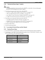
2-1.
Checklist of Installation Procedures
Following is a checklist of the procedures required during installation of an IMAGER:
- Uncrating and Initial Setup
. . . . . . . . . . . . . . . . . . . . . . . . . . . . . . . . . . . . . . . . . . Paragraph 2-3
- Unpacking . . . . . . . . . . . . . . . . . . . . . . . . . . . . . . . . . . . . . . . . . . . . . . . . . . . . . . . . . Paragraph 2-4
- Connecting to Electrical Power and the Network . . . . . . . . . . . . . . . . . . . . . . . . Paragraph 2-5
- Configuring the IMAGER . . . . . . . . . . . . . . . . . . . . . . . . . . . . . . . . . . . . . . . . . . . . . Paragraph 2-6
- Training Key Operators . . . . . . . . . . . . . . . . . . . . . . . . . . . . . . . . . . . . . . . . . . . . . . Paragraph 2-7
- Checking Temperature of the PROCESSOR . . . . . . . . . . . . . . . . . . . . . . . . . . . Paragraph 2-8
- Checking Image Quality . . . . . . . . . . . . . . . . . . . . . . . . . . . . . . . . . . . . . . . . . . . . . Paragraph 2-9
- Backing up the System Configuration . . . . . . . . . . . . . . . . . . . . . . . . . . . . . . . . . . Paragraph 2-10
- Editing the Service History Log . . . . . . . . . . . . . . . . . . . . . . . . . . . . . . . . . . . . . . . Paragraph 2-11
2-2.
Tools Required for Installation
•
VOLTMETER
•
LAPTOP COMPUTER
•
SERVICE TOOL (Service WebLink software installed on your LAPTOP COMPUTER)
2005 July Rev. B
7F3318
2-1
Service Manual
2-3.
2-3-1.
Uncrating and Initial Setup
Opening the Shipping Crate
1. Inspect the SHIPPING CRATE for damage.
2. Check the 2 “Tip N’ Tell” SHIPPING MONITORS for possible mishandling during shipment.
3. If damage or mishandling is evident, contact the shipper.
4. Remove the TOP PANEL: 3 PLASTIC CLAMPS. 11 METAL CLAMPS.
5. Remove RIGHT SIDE PANEL: 4 PLASTIC CLAMPS, 8 METAL CLAMPS.
6. Remove the top FOAM PACKING.
7. Remove the PLASTIC BAG containing the printed Kodak DryView 8150 LASER IMAGER SAFETY
MANUAL and the Kodak DryView 8150 LASER IMAGER USER DOCUMENTATION CD.
8. Read the SAFETY MANUAL.
2-2
7F3318
2005 July Rev. B
Section 2 -- Installation
2-3-2.
*
Completing the Uncrating
Important
Before completing the uncrating, check that there is an unobstructed space of 3 m (10 ft) in front of the crate.
1. Use a SCREWDRIVER to pry out and remove the PLASTIC CLAMPS remaining on the FRONT
PANEL.
2. Lay the FRONT PANEL on the floor in front of the IMAGER.
3. Remove the METAL CLAMPS from the bottom of the SIDE PANEL.
4. Remove the METAL CLAMPS from the bottom of the REAR PANEL.
5. Place a chair or similar item against the SIDE PANEL to keep it from falling.
6. Hold the REAR PANEL so it does not fall. Remove the METAL CLAMPS from the edge of the REAR
PANEL.
7. Remove the REAR PANEL and set it aside.
8. Remove the SIDE PANEL and set it aside.
9. Remove the FOAM PACKING.
2005 July Rev. B
7F3318
2-3
Service Manual
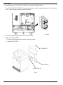
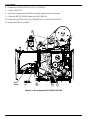
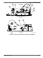
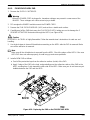
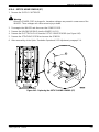
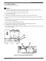
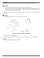
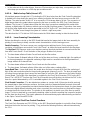
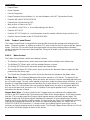
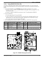
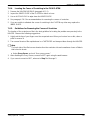
10. With SCISSORS, cut the FOIL BAG all around the base of the IMAGER.
11
10
11. Remove the FOIL BAG.
Note
The bottom of the FOIL BAG, under the Imager, will remain in place.
12. Remove the ACCESSORIES package. See page 2-7 for contents.
12
2-4
7F3318
2005 July Rev. B
Section 2 -- Installation
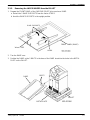
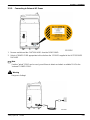
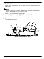
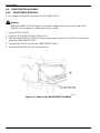
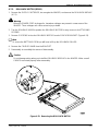
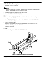
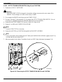
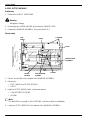
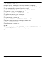
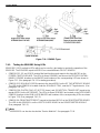
2-3-3.
Removing the LASER IMAGER from the PALLET
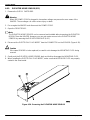
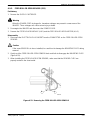
1. Prepare the FRONT PANEL of the SHIPPING CRATE to be used as a RAMP.
a. Detach the 2 RAMP SUPPORTS from the Velcro STRIPS.
b. Hook the RAMP SUPPORTS in the upright position.
RAMP SUPPORTS
FRONT PANEL (RAMP)
Velcro STRIP
HOOK
2. Turn the RAMP over.
3. Position the RAMP so the 2 BOLTS in the base of the RAMP insert into the holes in the METAL
PLATE on the PALLET.
RAMP
BOLTS
PALLET
METAL PLATE
2005 July Rev. B
7F3318
2-5
Service Manual
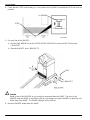
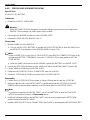
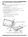
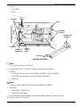
4. Check that the STOP is all the way up. If not, loosen the LOCKNUT and adjust the STOP up as far as
possible.
LOCKNUT
STOP
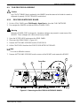
5. On each side of the IMAGER:
a. Use the Allen WRENCH from the ACCESSORIES PACKAGE to remove 4 BOLTS from each
L--BRACKET.
b. Discard the BOLTS and L--BRACKETS.
BOLT
L--BRACKET
!
Caution
Stand in front of the IMAGER as you control its movement down the RAMP. The force of the
IMAGER down the RAMP is about 36 kg (80 lb). Be careful not to tip the IMAGER or allow it to roll
off the side of the RAMP. The IMAGER weighs 204 kg (450 lb).
6. Move the IMAGER slowly down the RAMP.
2-6
7F3318
2005 July Rev. B
Section 2 -- Installation
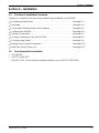
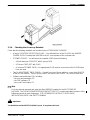
2-3-4.
Checking the Accessory Materials
Check that the following materials are included in the ACCESSORIES PACKAGE:
•
A bag of 5 VOLTAGE SELECTION PLUGS -- You will install one of the PLUGS in the IMAGER
POWER SUPPLY to adapt the IMAGER to the AC source power at this customer site.
•
3 POWER CORDS -- You will select the required CORD from the following:
--
A North American CORD SET with 3--prong PLUG
--
A Chinese CORD SET with PLUG
--
A “universal” POWER CORD -- An appropriate PLUG must be connected on this CORD before
it can be used.
•
Two RJ-45 INTERNET DROP CABLEs -- You will use one of these cables to connect the IMAGER
to the DICOM network. There is a long CABLE and and a short CABLE. You can use either one.
•
Software and publication CDs, including:
-- the user documentation CD
-- the DRE software CD
-- the Local Panel videos CD
Note
You have already removed and used the Allen WRENCH supplied in the ACCESSORIES
PACKAGE. The USER DOCUMENTATION COMPACT DISK (CD) contains translated versions of the
following manuals in many languages: SITE--READINESS CHECKLIST, USER GUIDE,
INSTALLATION GUIDE, and SAFETY MANUAL.
*
Important
You should have read the SAFETY MANUAL by now. If not, please read it now.
2005 July Rev. B
7F3318
2-7
Service Manual
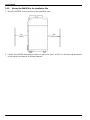
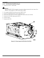
2-3-5.
Moving the IMAGER to the Installation Site
1. Move the IMAGER and accessories to the installation area.
1m
(39 in.)
1m
(39 in.)
2. Position the IMAGER temporarily so there is a space of a least 1 m (39 in.) in the front and at the back
of the machine for removal of packing materials.
2-8
7F3318
2005 July Rev. B
Section 2 -- Installation
2-3-6.
Checking Site Readiness
Check that the site is ready for installation of the IMAGER. Site Requirements are specified in the SITE
READINESS CHECKLIST for the Kodak DryView 8150 LASER IMAGER, 7F3336. The requirements
include:
•
Location Requirements.
•
One of the following AC power sources. within 2.5 m (8 ft) of the left rear corner of the IMAGER:
--
100 V AC ¦ 10%, 50/60 Hz ¦ 3 Hz
--
120 V AC ¦ 10%, 60 Hz ¦ 3 Hz
--
230 V AC ¦ 10%, 50 Hz ¦ 3 Hz
•
A network connection for a single modular RJ-45 plug within 8 m (26 ft) of the right rear corner of
the IMAGER.
•
Film of the correct size and type supplied by the customer.
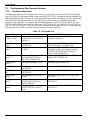
2-3-7.
Required Configuration Information
Check that the following customer information is available for configuration of the IMAGER:
•
The Network (Host) Name for the IMAGER
•
The Network Address for the IMAGER, including:
--
IP Address
--
Subnet Mask
--
Gateway
•
The DICOM Port Number for the IMAGER
•
A list of all MODALITIES that will connect to the IMAGER. For each MODALITY the list should
include:
•
--
Manufacturer
--
Modality Type (CR, DR, etc.)
--
Model Name
--
Film type to be used
--
Film size to be used
The following information is required for installation of RMS:
The following are the same as provided for the
Network Configuration:
--
Customer Name
--
Customer Department
--
Region
--
Node name
--
Country
--
IP Address
--
Location
--
Subnet Mask
--
Gateway
Continued
2005 July Rev. B
7F3318
2-9
Service Manual
--
Proxy Server Address1
--
Proxy Server Port1
--
Authentication Type1
--
Proxy Server Username1
--
Proxy Server Password1
1 Required
2-10
The following are obtained from the Imager during
installation:
--
K--number (found on Local Panel System
Information screen)
--
Serial Number (under the hood on the front
of the Imager)
if used at location
7F3318
2005 July Rev. B
Section 2 -- Installation
2-4.
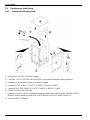
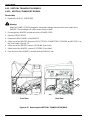
2-4-1.
Unpacking
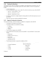
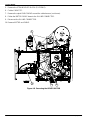
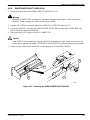
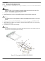
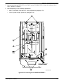
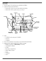
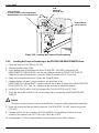
Removing the Packing Materials from the Back of the IMAGER
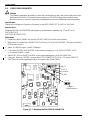
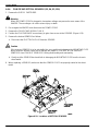
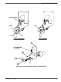
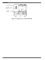
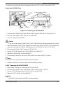
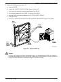
1. Remove and save 9 SCREWS, circled in the diagram, from the REAR PANEL.
SCREWS (9)
REAR PANEL
2. Remove the REAR PANEL.
2005 July Rev. B
7F3318
2-11
Service Manual
!
Caution
CABLE TIES were installed in the IMAGER to restrain movable assemblies during shipment. When
instructed to cut and remove a CABLE TIE, make sure that you remove the entire plastic CABLE
TIE, to avoid damage to the IMAGER. Take care not to cut any WIRES or damage any mechanical
parts or assemblies.
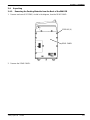
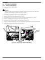
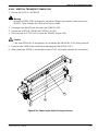
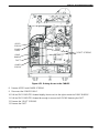
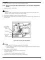
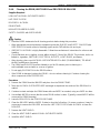
3. Cut and remove 2 CABLE TIES and TAGS from the FILM PICKUP AY.
4. Cut and remove the CABLE TIE and TAG from the TRANSLATION MOTOR.
5. Remove the TAPE and FOAM from the top of the PLATEN AY.
6. Pull out the 2 PLASTIC TUBES.
FILM PICKUP AY
3
TRANSLATION
MOTOR
4
PLATEN AY
5
6
2-12
7F3318
2005 July Rev. B
Section 2 -- Installation
2-4-2.
!
Removing the Packing Materials from the Front of the IMAGER
Caution
Whenever you raise or lower the HOOD, grasp the HOOD only in the area of the recessed slot
below the LOCAL PANEL to avoid the possibility of pinching your fingers. Close the HOOD
carefully. Releasing and dropping the HOOD could damage the IMAGER.
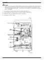
1. Grasp the HOOD in the recessed area below the LOCAL PANEL.
2. Raise the HOOD until the SUPPORT ROD locks into place.
3. Insert a small--diameter SCREWDRIVER or similar item in the slot at an angle, pointing toward the
rear of the IMAGER. Press down to unlatch the FRONT DOOR.
The DOOR will unlock and open
4. Close the HOOD.
5. Unlatch and open the PLATEN DOOR.
3
4
2
SUPPORT
ROD
PLATEN
DOOR
LATCH
1
5
2005 July Rev. B
7F3318
2-13
Service Manual
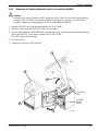
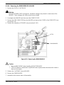
6. Remove the 2 SCREWS and 2 TAGS.
6
2-14
7F3318
2005 July Rev. B
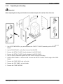
Section 2 -- Installation
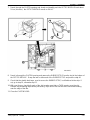
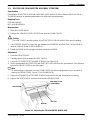
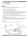
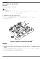
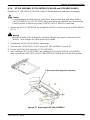
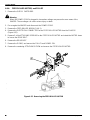
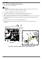
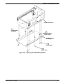
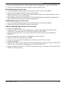
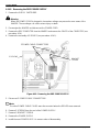
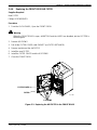
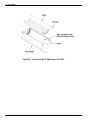
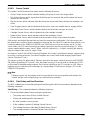
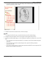
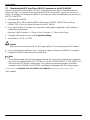
7. Reach through the PLATEN opening and slowly and steadily push the OPTICS MODULE back about
10 cm (4 inches). the OPTICS MODULE moves on RAILS.
9
9
7
8
10
8. Reach in through the PLATEN opening and remove the RUBBER STRIP from the slot in the bottom of
the OPTICS MODULE. Grasp the tab on either end of the RUBBER STRIP and peel the strip off.
9. Check that the double back tape, used to secure the RUBBER STRIP, is still attched to the strip. If
not, go to step 10, otherwise step 11.
10. With your fingers, check both ends of the slot to make sure that no TAPE remains over the slot.
Remove any remaining tape before proceeding. Tape left on this slot will cause horizontal banding
near the edge of the film.
11. Close the PLATEN DOOR.
2005 July Rev. B
7F3318
2-15
Service Manual
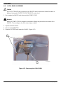
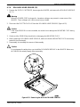
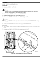
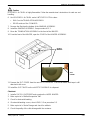
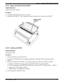
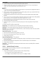
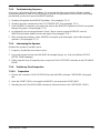
2-4-3.
Installing the CHARCOAL FILTER
1. Lift the FILTER RETAINING CLIP.
2. Pull the PLASTIC BAG and the CHARCOAL FILTER from the IMAGER.
3. Remove and discard the PLASTIC BAG.
2
1
3
4. Insert the CHARCOAL FILTER into the enclosure.
5. Push down the RETAINING CLIP so it locks into place.
6
4
5
6. Close the FRONT DOOR.
2-16
7F3318
2005 July Rev. B
Section 2 -- Installation
2-4-4.
!
Checking that Unpacking is Complete
Caution
If all packing materials are not removed from the IMAGER as instructed on the preceding pages,
the IMAGER will be damaged when power is applied.
1. Check that you have removed from the back of the IMAGER:
•
2 PLASTIC TUBES from the bottom of the PLATEN AY (see page 2-12)
•
TAPE and FOAM from the top of the PLATEN AY (see page 2-12)
•
One CABLE TIE and TAG from the TRANSLATION MOTOR (see page 2-12)
•
2 CABLE TIES and TAGS from the FILM PICKUP AY (see page 2-12 )
2. Check that you have removed from the front of the IMAGER:
•
2 SCREWS and TAGS from the PLATEN AY (see page 2-14)
•
RUBBER STRIP from the slot in the OPTICS MODULE (see page 2-15)
•
PLASTIC BAG from the CHARCOAL FILTER (see page 2-16)
3. Close the FRONT DOOR.
4. Discard the packing materials.
2-5.
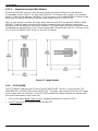
2-5-1.
Connecting to Electrical Power and the Network
Electrical Power Setup
1. Use a VOLTMETER to measure the AC voltage at the wall outlet that will be used by the IMAGER.
2. From the bag of 5 VOLTAGE SELECTION PLUGS supplied in the ACCESSORIES PACKAGE, select
the PLUG that matches the measured wall voltage:
For Measured Voltage of:
Select PLUG with:
90 -- 105 V AC
Brown Wires
106 -- 130 V AC
Red Wires
180 -- 210 V AC
Orange Wires
211 -- 230 V AC
Yellow wires
231 -- 250 V AC
Blue Wires
2005 July Rev. B
7F3318
2-17
Service Manual
3. Insert the correct VOLTAGE SELECTION PLUG into the POWER SUPPLY.
The VOLTAGE SELECTION PLUG is keyed so that it can only be inserted one way. Do not force the
PLUG. When oriented correctly, it will insert easily.
4. Discard the remaining VOLTAGE SELECTION PLUGS.
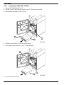
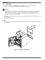
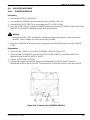
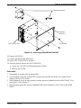
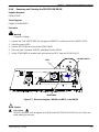
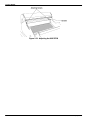
5. Replace the REAR PANEL:
a. Engage the bottom tabs and rotate the top into position.
b. Install the 9 SCREWS.
SCREWS (9)
BACKPANEL
Bottom Tabs (3)
2-18
7F3318
2005 July Rev. B
Section 2 -- Installation
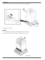
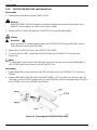
2-5-2.
Connecting to External AC Power
1. Remove and discard the CAUTION LABEL from the REAR PANEL.
2. Select a POWER CORD appropriate to this site from the 3 CORDS supplied in the ACCESSORIES
PACKAGE
Note
If neither ”whole” CORD can be used, you will have to obtain and attach a suitable PLUG to the
“universal” POWER CORD.
!
Warning
Dangerous Voltage!
2005 July Rev. B
7F3318
2-19
Service Manual
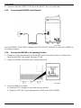
3. Connect the selected POWER CORD, first to the IMAGER, then to the wall outlet.
2-5-3.
Connecting the IMAGER to the Network
Use the INTERNET DROP CABLE supplied in the ACCESSORIES PACKAGE to connect the IMAGER to
the customer network.
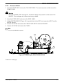
2-5-4.
Securing the IMAGER in its Operating Position
1. Review the Location Requirements for the IMAGER. Refer to the Site Readiness Checklist for the
Kodak DryView 8150 Laser Imager, document 7F3336.
2. Position the IMAGER precisely where it normally will be used.
3. Secure the IMAGER in position.
a. Rotate the STOP clockwise by hand until it touches the floor.
b. Tighten the LOCK NUT finger--tight against the BASE of the LASER IMAGER.
2-20
7F3318
2005 July Rev. B
Section 2 -- Installation
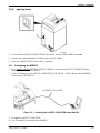
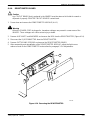
2-5-5.
Applying Power
1. Check that the HOOD and FRONT DOOR are closed, and the REAR PANEL is installed.
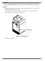
2. Remove the protective plastic COVER from the LOCAL PANEL.
3. Press the POWER SWITCH to the ON ( | ) position.
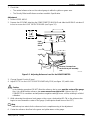
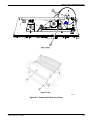
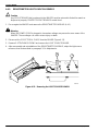
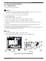
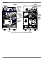
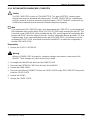
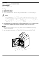
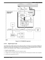
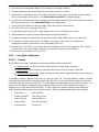
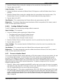
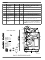
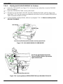
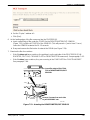
2-6.
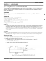
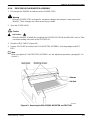
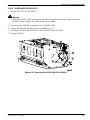
Configuring the IMAGER
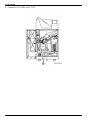
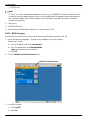
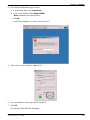
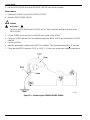
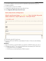
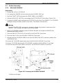
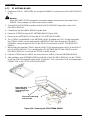
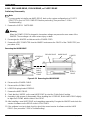
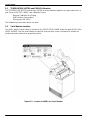
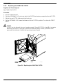
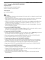
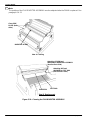
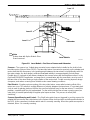
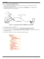
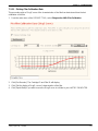
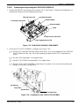
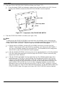
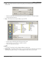
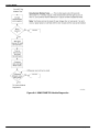
1. Use a straight--through INTERNET PATCH CABLE to connect your LAPTOP COMPUTER to the
Service Port under the TOP HOOD.
2. Set the IP Address of your LAPTOP COMPUTER to 192.168.0.2 -- (the IP address of the IMAGER
service port is 192.168.0.1).
INTERNET PATCH CABLE
Figure 2-1. Connecting the LAPTOP COMPUTER to the IMAGER
3. Energize the LAPTOP COMPUTER.
4. Use “SecureLink” to connect to the IMAGER.
2005 July Rev. B
7F3318
2-21
Service Manual
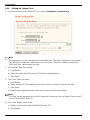
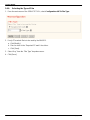
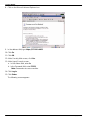
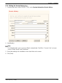
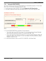
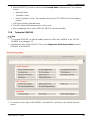
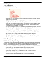
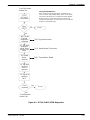
5. Launch “Service WebLink” to display the main menu of the SERVICE TOOL.
6. Expand the “Configuration” menu items.
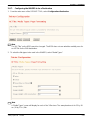
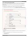
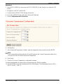
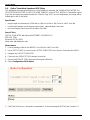
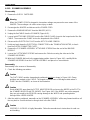
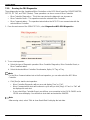
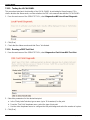
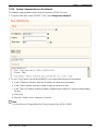
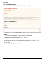
2-6-1.
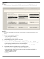
Setting the “Host Name” and the “IP Address”
1. Obtain from the customer the “Host Name”, “IP Address”, “Subnet Mask”, and “Gateway” that will
identify this IMAGER on the network.
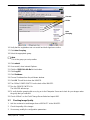
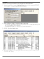
2. From the main menu, select Configuration>System>Network.
3. Click [Modify].
Note
The Host Name is the network name for this IMAGER. It can be a maximum of 14 characters and a
minimum of one. The first character must be a letter. Other characters can be a letter, number or a --.
4. Enter:
•
“Host Name”
•
“IP Address”
•
“subnet Mask”
•
“Default Gateway”
5. Click [Save].
6. Restart the IMAGER from the LOCAL PANEL to enter the network data into the system.
Note
The Host Name and IP Address data can also be entered from the LOCAL PANEL: Main
Menu>Setup Imager>Network Setup. (IMAGER must be restarted.)
2-22
7F3318
2005 July Rev. B
Section 2 -- Installation
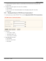
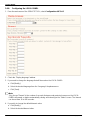
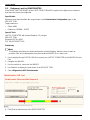
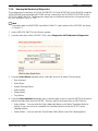
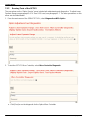
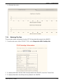
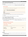
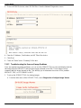
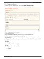
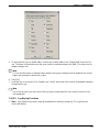
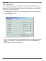
2-6-2.
Checking the Port Number of the “Secure Tunnel”
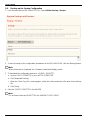
1. From the main menu of the SERVICE TOOL, select Configuration>System>SecureLink.
2. Check that the “Port” setting is 443.
Note
If the Port setting is not 443, you will not be able to back up the configuration.
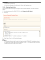
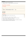
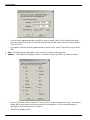
3. If the Port setting is not 443:
a. Click [Modify].
b. Type : 443
c. Click [Save].
d. Restart the IMAGER from the LOCAL PANEL.
2005 July Rev. B
7F3318
2-23
Service Manual
2-6-3.
Setting the System Clock
1. From the main menu of the SERVICE TOOL, select Configuration >System>Clock.
Note
The system clock is set in manufacturing. At installation, the “Time Zone” setting has to be changed
if the IMAGER is installed in a different time zone. When the “Time Zone” setting is changed, the
“Time” and “Date” should display correctly.
2. To correct the “Time Zone” setting:
a. Click [Modify].
b. Select the correct Time Zone from the “Time Zone” dropdown menu.
c. Click [Save].
3. If the “Time” value is incorrect:
a. Click [Modify].
b. Select a field in the “Time” window and use the Arrows to increase or decrease the time.
c. Click [Save].
d. Notify Service Engineering that the time was incorrect and had to be changed.
Note
The “Date” can be changed only by Level 5 personnel. If necessary, you can obtain 24 hours Level 5
access to the IMAGER from TSC.
4. If the “Date” display is not correct:
a. Obtain Level 5 access to the the IMAGER from the TSC.
b. Click ]Modify].
2-24
7F3318
2005 July Rev. B
Section 2 -- Installation
c. Use the “Date” dropdown calendar, or select fields in the “Date” window to change the date.
d. Click [Save].
5. If daylight saving time applies in the area of the installation:
a. Click [Modify].
b. Place a check in the “Automatically adjust clock for daylight savings time” check box.
c. Click [Save].
2-6-4.
Checking the Values for “DICOM Source Communications”
1. From the main menu of the SERVICE TOOL, select Configuration>DICOM SCP>Communications.
2. Check that:
•
“Port number is “5040”.
•
“Association Limit” is “12”.
•
“Source Name” is “DICOM”.
3. If the values are not correct:
a. Click [Modify].
b. Enter the correct values.
c. Click [Save].
2005 July Rev. B
7F3318
2-25
Service Manual
2-6-5.
Setting up Service Tracking
1. From the main menu of the SERVICE TOOL, select System Information>Identification.
2. Click [Modify].
3. Enter the correct information in the following fields:
•
“Model Name”
•
“Service Phone Number”
•
“Phone Number”
Note
The K--Number should match the decal on the machine. Serial number changes require Level 5
certification.
4. Click [Save].
2-6-6.
Configuring “SCP Services”
The Kodak DryView 8150 LASER IMAGER comes with a Modality Preferences Databse (MPDB). When a
modality sends information to the 8150 the first time, the software will look at the DICOM unique ID and
check for a match in the MPDB table. If it finds a match, it will send a TFT and contrast/density settings.
Note
Before this configuration procedure can occur, each MODALITY that will use this IMAGER must
send an image to it.
1. From the main menu of the SERVICE TOOL, select Configuration>DICOM SCP>SCP Services.
2-26
7F3318
2005 July Rev. B
Section 2 -- Installation
Note
The SERVICE TOOL will display a screen of “Image Optimization” parameters with default parameter
values selected from the Modality Preferences Database in the DRE.
•
Note
The parameter default values on the screen apply to the MODALITY identified in the “SCU”
window at the top of the screen.
2005 July Rev. B
7F3318
2-27
Service Manual
•
The information in the “SCU” window includes, in order: IP Address and AE Title of the SCU
sender, and AE Title of the destination.
•
You can open the “SCU” window to display a dropdown list of all SCUs connected to the IMAGER.
•
You must do “Image Optimization” and “Other Options” for each SCU in the dropdown list.
2. Check each default parameter on the “Image Optimization” screen.
3. Do the following to determine whether a change to a default parameter is necessary:
a. Check the DICOM log for details relating to the print job sent down from the MODALITY. The
parameter values on the “Image Optimization” screen should match any values sent from the
MODALITY.
b. See Table 2-1 for descriptions of the parameters and recommended settings.
c. Refer to paragraph 2-12 at the end of this section for recommended settings, by type of
MODALITY, for the following parameters: TFT Set Name, Contrast, Smoothing Type, and Image
Dmax.
d. Check the quality of printed images sent from the MODALITY.
Table 2-1. Selecting the ’Image Optimization” Parameters
Parameter
Description
Negotiate Presentation PLUT
Some SCUs can apply standard PLUT parameters that provide improved tone scaling of images. The SCP must agree to negotiate this PLUT.
YES, for those SCUs with PLUT
capability.
Negotiate Color
Print
TFT Set Name
Determines if the SCP will negotiate the Color
Print Service if requested by the SCU.
Name of a particular set of 15 TFT curves. Each
curve in the set is identified by a corresponding
user--selectable contrast number, 1-15.
NO
Contrast
The number selected determines which table
from the set of 15 will be used.
See paragraph 2-12. You may
need to run contrast test prints at
various settings to select the correct contrast value.
For “Always Apply...”, select NO.
Smoothing Type A smoothing value (0-15) specifies a level of
smoothness/sharpness in transitions between
density levels on the image.
Image Dmin
Image Dmax
Image Polarity
Recommended Setting
See paragraph 2-12.
For Always Apply..., select NO.
See paragraph 2-12.
For Always Apply...”, select NO.
Minimum density of the image.
0.0
For “Always Apply..., select NO.
Maximum density of the image. Cannot be higher See paragraph 2-12.
than border density.
For “Always Apply...,” select NO.
The polarity of the printed image with respect to
the image from the SCU. NORMAL (default)
specifies same polarity, REVERSE the opposite.
POSITIVE for most SCUs. NEGATIVE for Nuclear Medicine.
For “Always Apply..., select NO.
4. To change a parameter value, if necessary:
•
Click [Modify].
•
Select the desired parameter from the dropdown menu for the parameter.
•
Click [Save].
2-28
7F3318
2005 July Rev. B
Section 2 -- Installation
Note
For some parameters you have the option to “Always Apply...”. If you select YES, the parameter on
the screen will override the parameter that the SCU sends. If you select NO, the SCU parameter will
apply. Normally you should allow the SCU to override.
5. After checking, and modifying, if necessary, the “Image Optimization” parameters, select “Other
Options” from the top of the screen.
2005 July Rev. B
7F3318
2-29
Service Manual
6. Check each parameter.
2-30
7F3318
2005 July Rev. B
Section 2 -- Installation
7. See Table 2--2 for descriptions of the “Other Options”. The default values shown on the screen have
been selected from the Modality Preferences Database in the DRE.
8. Change parameters only if necessary.
9. To change a parameter:
a. Select [Modify].
b. Select the new parameter value from the dropdown menu for that parameter.
c. Click [Save].
Table 2-2. Selecting “Other Options” Parameters
Parameter
Description
Recommended Setting
Send N_Event Reports
The IMAGER can automatically send
changes in its status to the SCU when the
changes occur.
Send Warnings
The IMAGER can also send non--fatal warn- YES, unless the user does not
ing messages to the SCU when problems oc- want the messages sent.
cur (film jams, etc.)
Print Priority
The order of printing from the SCUs can be
prioritized by selecting LOW, NORMAL, or
STAT (High) priority for particular SCUs,
Check with the user for the print
priority for this SCU.
For “Always Apply...”, select NO.
2mm Border
Selects 2mm border for non--requested
image size jobs.
Enbles use of clipping border of 22.1 mm for
jobs that have more than one image with a
requested image size that does not resize
images.
BLUE FILM or CLEAR FILM
The default is NO.
Film Clip Border
Film Base
YES, unless the user does not
want the reports sent. (Such reports can cause problems in some
SCUs.)
For “Always Apply...”, select NO.
The default is NO.
If the SCU does not send film
base type:
• Select the correct type.
•
Film Size
For “Always Apply...”, select
YES.
3 sizes are available: 14 x 17 in., 11 x 14 in.,
and 14 x 14 in.
Include print date in If the user wants the date of “image acquisiannotation
tion” to be annotated on the print, select YES.
Include print time in If the user wants the time of printing to be anannotation
notated on the print, select YES.
Include page num- If the user wants the page number sequence
ber in annotation
in a multi--page study to be annotated on the
prints, select YES.
Select the correct size.
For “Always Apply...”, select NO.
Check with user.
Include hospital
name in annotation
Check with user.
2005 July Rev. B
7F3318
If the user wants the hospital name to be annotated on the print, select YES. This name
will be the same as that entered on the Service Tracking screen.
Check with user.
Check with user.
2-31
Service Manual
Include modality ID
in annotation
If the user wants the modality ID to be annotated on the print, select YES. See the item
below.
Check with user.
Modality ID
The Modality ID indicated will be printed in
the Annotation Text Box on the print. The ID
includes the first 8 characters of the SCP
node Name plus the 2 last octets of the SCU
IP Address.
Check with user.
Annotation Override If you select YES, the values entered for all
the annotation parameters will override any
values sent down from the SCU.
Select NO.
Density Patch
Default is YES, but check with the
user.
Check with the user. If MINIFY/
SCALE is selected, the IMAGER
will determine which type of demagnification is to be used, either
MINIFY or SCALE.
Use of the Density Patch is selectable only
for 14 x 17 in. film.
The 2 options are MINIFY/SCALE or CROP.
• To “minify” is to decrease the image by
removing pixel data via a software
algorithm if the raw image is too large for
the film. When this occurs, the “minify”
icon is printed on the film. See Figure 2-2.
Image Resizing
•
To “scale” is to de--magnify, or scale
down, the image if the requested image
size is too large for the film. When this
occurs,the “scale” icon is printed on the
film. See Figure 2-2.
•
To “crop” is to remove the edges of the
image so it fits on the film. The uncropped
part of the image will remain true size.
When this occurs, the “crop” icon is
printed on the film. See Figure 2--2.
For Always Apply...”, select NO.
Some SCUs have the ability to indicate type of resizing and should
be allowed to override the default
value set in the IMAGER.
Text Box Location
This parameter applies only to “1-up” images
on 14 x 17 in. film, when crop has been selected for image resizing. Text Box Location
indicates the location on the page for the annotation box. The box can be cut and pasted
on the cropped image at the TOP or BOTTOM of the film.
Check with user for desired location. Select NONE if cropping is
not used.
Source ID
This is the source name used for logging DICOM communications from this SCU. It also
identifies the SCU in the SERVICE TOOL
print statistics.
Select a short name for the SCU.
Minify Icon
Scale Icon
Crop Icon
Figure 2-2. Cropping Icons
2-32
7F3318
2005 July Rev. B
Section 2 -- Installation
2-6-7.
Configuring the IMAGER to be a Destination
1. From the main menu of the SERVICE TOOL, select Configuration>Destination.
Note
The “AE Title” on the 8150 cannot be changed. The 8150 does not care what the modality uses for
an AE Title for the PMA destination.
2. To select the film types to be used in the IMAGER, select “Media Types”.
Note
A “Media Types” screen will display for each of the 3 film sizes. The example above is for 35 by 34
cm (14 by 17 in.) film.
2005 July Rev. B
7F3318
2-33
Service Manual
3. For all film sizes that will be used, select “Any (Blue or Clear)” for the “Media Type”.
Note
Do not change the default values shown for “Image Width” and “Image Height”. These values select
the maximum number of pixel positions for a “1--up portrait image” on the page. The “Image Height”
is reduced for pages with “annotation”. For page formats other than “1--up”, the following applies:
•
In any column of images on the page, the sum of all “Image Heights” plus all separations
between images cannot exceed the “Image Height” pixel value.
•
In any row of images on the page, the sum of all “Image Widths” plus the separations between
images cannot exceed the “Image Width” pixel value.
4. From the “Printer Configuration” screen, select “Page Formatting”.
5. Do not disable any of the Page Formatting Capabilities” of the IMAGER unless instructed to by the
customer.
6. Check the “Ranges” on the lower part of the screen.
2-34
7F3318
2005 July Rev. B
Section 2 -- Installation
Note
You must check with the user before changing any of the “Ranges” values.
7. If it is necessary to change any value on the “Page Formatting” screen:
a. Click {Modify].
b. Enter the new value.
c. Click [Save].
2005 July Rev. B
7F3318
2-35
Service Manual
2-6-8.
Configuring the LOCAL PANEL
1. From the main menu of the SERVICE TOOL, select Configuration>MCS>LP.
2. Check the “Display language” window.
3. If you need to change the language that will be used on the LOCAL PANEL:
a. Click [Modify].
b. Select the desired language from the “Language” dropdown menu.
c. Click [Save].
Note
“Key Access Timeout“ is the number of seconds that passcode-protected screens on the LOCAL
PANEL will remain on before automatically closing and returning to the “Status” screen. The timeout
can be set from 30 to 300 seconds.
4. If you wish to change the default timeout value:
a. Click [Modify].
b. Select the desired timeout value.
2-36
7F3318
2005 July Rev. B
Section 2 -- Installation
c. Click [Save].
Note
The “Key Operator Passcodes” section of the screen allows you to set passcodes that allow
operators to access the service functions of the LOCAL PANEL. You can also change the Service
passcode, labeled First Call 99 on this screen.
•
These passcodes can also be set directly from the LOCAL PANEL. See the User Guide for
instructions.
•
You can set the passcodes either now or during Operator Training.
5. Ask the operators to create the passcodes they wish to use. (They must be 6--digits, numeric only.)
6. If you wish to enter the passcodes at this time:
a. Click [Modify].
b. Type each 6--digit passcode.
c. Click [Save].
7. Change the Service Passcode.
The Service passcode is 123456 when the IMAGER leaves the factory. At this time change this
passcode to a new passcode that you choose. (The Service Passcode must be 6--digits, numeric
only.)
a. Click [Modify].
b. Type the new Service Passcode opposite “First Call 99”.
c. Click [Save].
8. If you modified any entry on the Local Panel Configuration screen, restart the system from the LOCAL
PANEL for the new value to take effect.
2005 July Rev. B
7F3318
2-37
Service Manual
2-6-9.
Selecting the Type of Film
1. From the main menu of the SERVICE TOOL, select Configuration>MCS>Film Type.
2. If only CE marked film is to be used by the IMAGER:
a. Click [Modify].
b. Place a check in the “Required CE mark” check box.
c. Click [Save].
3. Select “Any” from the “Film Type” dropdown menu.
4. Click [Save].
2-38
7F3318
2005 July Rev. B
Section 2 -- Installation
2-6-10. Setting up Remote Monitoring (RMS)
RMS uses the K--Number, Serial Number, Service Code, and Country to create the appropriate file
names. Accuracy in this area is important. The other data entered helps to create a profile on the
Enterprise server.
Before setting up RMS, contact TSC or xxxx to set up a group name under the appropriate region.
If this IMAGER is to be monitored remotely, configure it for remote servicing as follows.
1. From the main menu of the SERVICE TOOL, select Configuration>System>Remote Monitoring.
2. Click [Modify].
3. Enter into the appropriate windows the geographical and descriptive information that identifies this
IMAGER.
4. From the “Proxy Type” dropdown menu, select the type of proxy server at this location:
•
No Proxy (the default)
•
Standard Proxy
2005 July Rev. B
7F3318
2-39
Service Manual
•
NTLM Proxy
Note
A “Proxy” is a server that stands between a machine (e.g., the IMAGER) and the Internet to ensure
security and provide administrative control. It is associated with the gateway server that separates
the customer network from outside networks and the firewall server that secures the customer
network from intrusion.
5. Click [Save].
6. Click [Start Service].
7. Set up Remote Monitoring Grouping. Go on to procedure 2-6-11.
2-6-11. RMS Grouping
Perform this procedure after you have set up Remote Monitoring in procedure 2-6-10).
1. Using Symantec pcAnywheret remote access software, access the Imager:
At the Logon screen:
a. In the User Name Field, enter pcanywhere.
b. In the Password field, enter Netware28900.
Note: passwords are case sensitive.
c. Click OK.
2. Click the SEND Ctrl--Alt--Del to Host button.
SEND Ctrl--Alt--Del to Host
3. Log off the system.
a. Click Log Off.
b. Click Yes.
2-40
7F3318
2005 July Rev. B
Section 2 -- Installation
4. At the Microsoft Windows Logon screen:
a. In User Name field, enter pcanywhere.
b. In the Password field, enter Netware28900.
Note: passwords are case sensitive.
c. Click OK.
You will be prompted for a Secure Link Session ID.
5. Start a Secure Link Session to obtain an ID.
6. In the pcAnywhere screen, type in the Session ID.
7. Click OK.
The desktop of the IMAGER will appear.
2005 July Rev. B
7F3318
2-41
Service Manual
8. Click on the Microsoft Internet Explorer icon.
9. In the address field, type https://127.0.0.1:4433
10. Click Go.
11. Click OK.
12. At the Security Alert screen, click Yes.
13. At the Agent Console screen:
a. In User Name field, enter fe
b. In the Password field, enter FE123
Note: Passwords are case--sensitive.
14. Click Log In.
15. Click Status.
The following screen appears.
2-42
7F3318
2005 July Rev. B
Section 2 -- Installation
Success
Online
Auto
Grouping
16. Verify that the registration was successful and both Agents are online.
17. Click Auto Grouping.
18. Select the appropriate group.
Note
This is the group you set up earlier.
19. Click submit.
20. If successful, close Internet Explorer:
21. Click the SEND Ctrl--Alt--Del to Host button.
22. Click Log Off.
23. Click Shutdown.
24. Choose Shutdown from the pull--down window.
25. Click OK. This will shut down the IMAGER.
26. Turn Off the POWER SWITCH on the back of the IMAGER.
27. Turn the POWER SWITCH On.
The IMAGER will start up.
28. To verify that the grouping did occur, log on to the Enterprise Server and check for your Imager under
the group that you selected.
29. Check off Mod 1 on the Field Change Record label and report M01.
2-7.
Checking Image Quality
1. Ask the customer to send images from a MODALITY to the IMAGER.
2. Check the quality of the images.
3. If necessary, modify the configuration parameters.
2005 July Rev. B
7F3318
2-43
Service Manual
2-8.
Backing up the System Configuration
1. From the main menu of the SERVICE TOOL, select Utilities>Backup / Restore.
2. To store a backup of the configuration parameters on the DRE HARD DISK, click the [Backup] button.
Note
When the backup is completed, the “Summary” window will display results.
3. To download the configuration backup to a FLOPPY DISKETTE:
a. Insert a FLOPPY DISKETTE in your LAPTOP COMPUTER.
b. Click [Download Backup].
c. When the “Save Copy As” screen appears, select the A drive and enter a file name for the backup
file.
d. Click [Save].
4. Store the FLOPPY DISKETTE in the IMAGER.
Note
Do not leave the backup DISKETTE in the IMAGER FLOPPY DRIVE.
2-44
7F3318
2005 July Rev. B
Section 2 -- Installation
2-9.
Training Key Operators
Prepare key operators to use the IMAGER as follows:
1. Refer to the USER GUIDE for the Kodak DryView 8150 LASER IMAGER, and train the operators in
the basic machine functions.
2. If you did not assign operator passcodes while configuring the LOCAL PANEL, do so now. See
paragraph 2-6-8 .
There are 3 levels of operator access to the IMAGER (see Table 2-3).
•
Ordinary operators -- no passcode required
•
Key operators (User ID 0--10) -- Passcode required, assigned by FE or customer installer
•
Customer Installer (User ID 99) -- Passcode required, changed at installation
Note
If the customer has a Customer First technician, this person is assigned a special passcode required
for resetting the PM count.
Table 2-3. Levels of Customer Access to IMAGER
Tasks
Ordinary
Operators-No Passcode
Key Operators-ID 0-10 + Passcode
Customer Installer-ID 99 + Passcode
Shut down IMAGER
x
x
x
Open FRONT DOOR
x
x
x
Calibrate film
x
x
x
Run density test
x
x
x
IMAGER on line/off line
x
x
x
Printer enable/disable
x
x
x
Ping
x
x
x
Change FILTER
x
x
x
View system information
x
x
x
View versions
x
x
x
View print count
x
x
x
View jobs
x
x
x
View current errors
x
x
x
Change language of LOCAL PANEL
x
x
x
Log off
x
x
Delete queued print jobs
x
x
Delete “waiting for media” print jobs
x
x
Delete unprintable jobs
x
x
Adjust touch volume
x
x
Adjust backlighting of LOCAL PANEL
x
x
Adjust audible alarm
x
x
Edit service phone number
x
x
2005 July Rev. B
7F3318
2-45
Service Manual
Date format
x
Date
x
Time format
x
Time
x
Network name
x
IP Address
x
Subnet mask
x
Gateway
x
Ping from network setup screen
x
DICOM port
x
Set up modality
x
Change/create passcodes
x
Calibrate touch screen
x
Back up configuration
x
Restore configuration
x
Install IMAGER
x
Add image sources
x
Note
• Kodak Level 4 (FEs) and Level 5 (SE and TSC) service personnel can access all machine
functions shown in the table via SecureLink.
•
2-46
Kodak Level 5 personnel can access IMAGER functions via Remote Management Services
7F3318
2005 July Rev. B
Section 2 -- Installation
2-10. Editing the Service History Log
1. From the main menu of the SERVICE TOOL, select System Information>Service History.
2. Click [Modify].
Note
The following fields on the screen are filled in automatically: “DateTime”, “Service Code”, and your
Secure Tunnel “UserID” and “UserName”.
3. Enter data relating to the installation in the other fields on the screen.
4. Click [Save].
2005 July Rev. B
7F3318
2-47
Service Manual
2-11. Guidelines for Selecting the Correct TFT Set and Related Parameters
This section provides basic information that will help you to select the proper values for the following
’Image Quality” parameters that must be input during configuration of SCP Services (see procedure
2-6-6).
•
TFT Set Name
•
Contrast
•
Image Dmax
•
Smoothing Type
2-11-1. Definitions
Item
Description
TFT
A table, or curve, used in closed loop Kodak DryView LASER IMAGERS that relates each
digital input value to a corresponding target value of perceived brightness.
A set of 15 TFTs that represent 15 different curve shapes, each of which is associated
with a corresponding user-selectable contrast selection, 1-15. See paragraph 2-12-3 for
descriptions of individual TFT Sets.
TFT Set
Contrast
Density
A user-selectable value from 1-15 that selects the correct TFT from the TFT Set for the
current print.
A user-selectable value that determines the maximum density (Dmax) used in printing.
Smoothing
Type
PLUT
A user-selectable value (1-15) that specifies a level of smoothness/sharpness in transition between density differences on film.
Presentation LookUp Table
GSDF
Grayscale Standard Display Function
2-11-2. Selecting the Image Quality Parameters Appropriate to the MODALITY
Use Tables 2-4 and 2-5 to select the “Image Quality” parameters. The selections are based on
MODALITY type. They also depend on whether the MODALITY is GSDF-compliant and whether it uses
PLUTs.
•
If the MODALITY is not DICOM GSDF-compliant, use the procedure in paragraph 2-12-3.
•
If the MODALITY is DICOM GSDF-compliant and does not PLUTs or uses PLUTs for only some
images, use the procedure in paragraph 2-12-4.
•
If the MODALITY is DICOM-GSDF-compliant and uses PLUTs for all images, do not use either
procedure. Leave the “Image Quality” parameters at the default values set by the Modality
Preferences Database.
2-48
7F3318
2005 July Rev. B
Section 2 -- Installation
2-11-3. Selecting Parameters for MODALITIES that are not DICOM-GSDF-Compliant
1. Refer to Table 2-4 and find the type of MODALITY for which the IMAGER is being configured.
2. Select the TFT Set recommended in Table 2-4 for this type of MODALITY. If more than one set is
listed, read the notes in the table for guidance in selecting the appropriate set.
3. Select the Table No. (contrast setting) recommended for the chosen TFT Set. If a number is in “bold,”
select this number first (You may have to try more than one Table No, during the configuration
process.)
4. Select the Image Density associated with the Table No. you chose. If there is a range of densities:
•
Select the density value indicated in bold, if there is one.
•
If there is no bold value, select the middle value. For example, if the range is 2.7 to 3.1, select 2.9.
•
If there are only 2 density values, select either one.
5. Select the Smoothing Type recommended in Table 2-4.
6. Enter the selected parameter values on the “Image Optimization” screen in the SERVICE TOOL.
2-11-4. Selecting Parameters for DICOM GSDF-Compliant MODALITIES
Note
This procedure does not apply to GSDF-Compliant MODALITIES that use PLUTs for all images.
1. Use TFT Set GSDF0.87.
2. Refer to Table 2-4 and find the type of MODALITY for which the IMAGER is being configured.
3. Select the Density (Dmax) recommended for this type of MODALITY. If there is a range of densities:
•
Select the density value indicated in bold, if there is one.
•
If there is no bold value, select the middle value. For example, if the range is 2.7 to 3.1, select 2.9.
•
If there are only 2 density values, select either one.
4. Refer to Table 2-5 and select the Table No. (contrast setting) that corresponds to the chosen Density
(Dmax) value.
5. Refer to Table 2-4 and select the Smoothing Type for the selected type of MODALITY.
6. Enter the selected parameter values on the “Image Optimization” screen in the SERVICE TOOL.
2005 July Rev. B
7F3318
2-49
Service Manual
Table 2-4. Recommended TFT Sets for MODALITIES
Type of MODALITY
TFT Set
Table No.
(Contrast)*
Density
(Dmax)*
Smoothing
Type
Notes
Kodak and other CR
(Computed Radiography) and DR (Digital
Radiography) Systems.
Also Workstations and
imaging devices that
output data to a linear-in--density contrast
curve.
Fuji CR
WRKSTN2A 1
2
3
4
3.1
3.0
2.9
2.8
5
Select Table number
(contrast) and Dmax in
the pairs shown. Do not
use with Fuji CR.(See
Fuji CR below.)
FCR302C4
2.6
2.7
2.8
2.9
3.0
3.1
5
Table number (contrast)
and Dmax must be chosen in the pairs shown.
The contrast curves are
approximately linear in
density for most of the
pixel value range, but
become relatively flat at
high (bright) pixel values. Designed for use
with Fuji CR only.
CT (Computed
Tomography) or MRI
(Magnetic Resonance)
VER693C30 5, 7, 8
3.0--3.1
15
Table 7 provides good
grayscale range in all
CT and MRI studies.
Table 5 has less mid-tone contrast. Table 8
has more mid--tone contrast.
DSA (Digital Subtraction Angiography), including
C--Arm and Digital
Fluoro
VER713C0 6, 7, 9
Alternative 1
2.9--3.1
15
VER713C0 provides
brighter image background than
VER693C0. Lower table
numbers have less
mid--tone contrast.
Higher have more.
VER693C0 6, 7, 9
Alternative 2
2.9--3.1
15
VER693C0 provides
darker image background than
VER713C0. Lower
Table numbers have
less mid--tone contrast.
Higher have more.
10
11
12
13
14
15
Note: * The number in bold should be the first choice when you are selecting parameter values.
2-50
7F3318
2005 July Rev. B
Section 2 -- Installation
Phillips Medical SysPMSV3K
tems (PMS) -- EasyVision and other PMS modalities.
9
3.0, 3.1
15
Table No.
(Contrast)*
Density
(Dmax)*
Smoothing
Type
VER713C0 5--7--10
Alternative 1
2.2, 2.3
12
Table 7 is popular. Table
5 has less mid--tone
contrast and shows
more isotope takeup.
Table 10 has more mid-tone contrast and reduces takeup visibility
on film.
PMSV3K
10--14
Alternative 2
2.2, 2.3
12
Start with Table 10.
Higher tables have increased brightness and
reduce isotope takeup
visibility on film. Lower
tables show more
takeup.
Siemens Host Control
or WORKSTATION
WRKSTN2A 4
2.8
15
Ultrasound
VER693C0 5--8--12
Alternative 1
2.4--2.8
15
Typically the density is
set to 2.8 by the Siemens host control software. Table 4 must be
chosen for linear
grayscale translation.
Table number choices
vary with manufacturer
and radiologist. Lower
table numbers have
less mid--tone contrast.
Higher numbers have
more.
PMSV3K
7--10--13
Alternative 2
2.4--2.8
15
Type of MODALITY
Nuclear Medicine
TFT Set
Check with the PMS
service engineer. On
some PMS MODALITIES, image quality calibration must be run
from the PMS control
console.
Notes
Table number choices
vary with manufacturer
and radiologist. Higher
table numbers have increased brightness.
Note: * The number in bold should be the first choice when you are selecting parameter values.
2005 July Rev. B
7F3318
2-51
Service Manual
Table 2-5. GSDF0 Dmax Setting vs. Table Number (Contrast) Setting
Density (Dmax)
Table No. (Contrast)
1.7
1
1.7
2
1.8
3
2.0
4
2.1
5
2.2
6
2.3
7
2.4
8
2.5
9
2.6
10
2.7
11
2.8
12
2.9
13
3.0
14
3.1
15
Density and Table No. must be chosen in the
pairs shown.
2-52
7F3318
2005 July Rev. B
Section 2 -- Installation
2-11-5. TFT Set Descriptions
AIRIS2A: Designed to meet Hitachi requirements for a TFT SET, that, when used for printing on Kodak
DryView FILMS, can perceptually match films printed on a 969 HQ (wet) LASER IMAGER when TFT SET
VER693C0, with Contrast = 6 and Dmax = 3.0, is used in the HQ.
To do this, the AIRIS2A TFT SET is designed for overall similarity to the VER693C0 TFT SET, but
provides lower measured densities in the darker part of the density range. In the AIRIS2A SET, Contrast =
8 TFT is designed to provide dry prints which match the Contrast = 6 wet prints made using VER693C0
on an HQ, with Dmax = 3.0 for both prints.
The plots of this TFT SET indicate that all 15 of the tables have the same mid--tone brightness, with
varying degrees of an S--shape curve which gives the strongest end--point contrast, or slope, to Table 12
and the strongest mid--tone contrast to Table 15. Note that this TFT SET provides a narrower range of
curves than the VER693C0.
2005 July Rev. B
7F3318
2-53
Service Manual
B3C5AX4: Allows moderate departures from the basic VER693C0 curves. Curves 2, 5, 8, 11 and 14
roughly cover the span of VER693C0. The remaining curves provide more mid--tone brightness choices.
Curves 1, 4, 7, 10, and 13 = the brightest, and curves 3, 6, 9, 12, and 15 = the darkest. In all, there are 5
mid--tone contrast choices for each of 3 mid--tone brightness choices.
The plots on the chart indicate the two--dimensional brightness/contrast combinations provided by this
TFT SET. The numbering of the TFTs in the set is such that when a 3 (horizontally) x 5 (vertically) contrast
test film is printed, the printed images are of decreasing brightness going from left to right and increasing
mid-tone contrast going from top to bottom on the film.
C3B5AX4: Allows moderate--to--strong departures from the basic VER693C0 curves. Curves 7 through 9
cover roughly the span of VER693C0 and the remaining curves provide more choices of mid--tone
brightness. Curves 1 through 3 = the brightest, and curves 13 through 15 = the darkest. In all, there are 3
mid--tone contrast choices for each of 5 mid--tone brightness choices.
The plots on the chart indicate the two--dimensional brightness/contrast combinations provided by this
TFT SET. The numbering of the TFTs in the SET is such that when a 3, horizontally, x 5, vertically,
contrast test film is printed, the printed images are of decreasing brightness going from top to bottom and
decreasing mid--tone contrast going from left to right on the film.
2-54
7F3318
2005 July Rev. B
Section 2 -- Installation
FCR302C4: Created specifically for use with the 3M Model 2210 CREIB INTERFACE to a Fuji COMPUTED
RADIOGRAPHY SYSTEM. This TFT SET should not be used for any other application. The 15 TFTs in this
SET are designed to be used in correspondence with the 15 Dmax choices of the IMAGER, using Contrast
1 when the first Dmax value is used, etc. The plots in the chart below indicate a sagging shape, which is
characteristic of a “linear in density” behavior, until maximum brightness (Dmin) is approached, at which point
the curves become flat.
2005 July Rev. B
7F3318
2-55
Service Manual
GEHYB01: A hybrid TFT SET that supports the various imaging MODALITIES which might be connected
to a GE AMBER WORKSTATION. These MODALITIES include Fuji COMPUTED RADIOGRAPHY (CR),
CT, MR, Ultrasound and any MODALITY that expects a linear--in--density PRINTER. The following table
defines how the 15 TFTs can best be applied to the various MODALITIES supported by this TFT SET.
Contrast Value
Application
TFT No.
1 Fuji CR, with Dmax = 2.6
2 Fuji CR, with Dmax = 2.7
3 Fuji CR, with Dmax = 2.8
4 Fuji CR, with Dmax = 2.9
5 Fuji CR, with Dmax = 3.0
6 Linear in Density, Dmax = 2.6
7 Linear in Density, Dmax = 2.6
8 Linear in Density, Dmax = 2.6
9 Linear in Density, Dmax = 2.6
10 Linear in Density, Dmax = 2.6
11 Ultrasound -- highest mid--tone brightness
12 Ultrasound -- moderate mid--tone brightness
13 Ultrasound, CT or MR
14 CT or MR
15 CT or MR
2-56
7F3318
2005 July Rev. B
Section 2 -- Installation
GSDF0: A TFT SET in which all 15 curves are designed to conform to the “NEMA Grayscale Standard
Display Function” as applied to the case of transmissive film media under certain typical conditions. For
optimum conformity with the standard, select the contrast value in this TFT SET based upon the Dmax
value in the following table:
Dmax Optimum Contrast Value
1.7 . . . . . . . .
1
1.8 . . . . . . . .
2
1.9 . . . . . . . .
3
2.0 . . . . . . . . . . . . . . . 4
2.1 . . . . . . . .
5
2.2 . . . . . . . .
6
2.3 . . . . . . . .
7
2.4 . . . . . . . .
8
2.5 . . . . . . . .
9
2.6 . . . . . . . .
10
2.7 . . . . . . . . . . . . . . . 11
2.8 . . . . . . . . . . . . . . . 12
2.9 . . . . . . . . . . . . . . . 13
3.0 . . . . . . . .
14
3.1 . . . . . . . .
15
2005 July Rev. B
7F3318
2-57
Service Manual
HYB60516: A hybrid TFT SET that supports the diverse needs of several imaging MODALITIES that might
be operating within a Lockheed (formerly Loral) network. These MODALITIES include Fuji COMPUTED
RADIOGRAPHY (CR), Digital Subtraction Angiography (DSA or DSI), C--ARM applications, CT, MR,
Ultrasound and Nuclear Medicine. The following table defines how these 15 individual TFTs can best be
applied to the needs of various imaging MODALITIES supported by this TFT SET
Imaging
Suitable Preferred
MODALITY
Dmax Range Dmax
Fuji CR
2.7--3.0
3.0
DSI (DSA )
3.0
3.0
C--Arm
3.0
3.0
CT
3.0
3.0
MR
3.0
3.0
Ultrasound
2.5
2.5
Nuclear Medicine 2.3
2.3
2-58
Suitable TFT
Contrast Value
2
4--7
1--4
2--7
1--7
3, 5--7, 11--15
Preferred TFT
Contrast Value
2
4
1
2
2
9
12
7F3318
2005 July Rev. B
Section 2 -- Installation
MAXXUS: Created specifically for use with the YMS SPECT to match Konica film. All 15 curves are very
close to a single curve. The MAXXUS TFT SET provides a SET of tables suitable for certain nuclear
medicine applications, specifically, to provide a flat, low contrast, curve shape in the brightest portions of
an image. This minimizes the visibility of soft tissue in a bone nuclear medicine image in which bone is
printed black on a white background. This is a tight TFT SET, offering limited variation with contrast value.
MSFDUP1: Designed to meet the density printing requirements of a TFT--based LASER IMAGER for
Kodak that is used as the PRINTER in a Kodak DUPLICATOR equipped with a MULTI--SHEET FEEDER.
The 15 individual TFTs of this TFT SET are designed to map 15 different Dmin and Dmax nominal input
ranges, original film, into the full density range of the IMAGER, approximately 0.2 to 3.1, for blue film.
Example: If the original film is a blue--based film from a LASER IMAGER, with a film Dmin of about 0.2
and a printed Dmax of about 3.0, a reasonable contrast value for duplicating this film would be 11. Since
these input density ranges are approximate, other similar values, 6 in this example, could give optimal
results from a user perspective. See the following table of nominal contrast values.
Nominal Contrast Values*
Dmin
Dmax ~ 3.0
Dmax ~ 3.2
Dmax ~ 3.4
~ 0.05
C=1
C=2
C=3
~ 0.12
C=6
C=7
C=8
~ 0.20
C = 11
C = 12
C = 13
* For various original film density ranges.
2005 July Rev. B
7F3318
Dmax ~3.6
C=4
C=9
C = 14
Dmax ~ 3.8
C=5
C = 10
C = 15
2-59
Service Manual
PMSB: Developed as a modification to the PMSV3K TFT SET that was previously developed for Philips
MEDICAL SYSTEMS. This SET was made by adjusting the t--values within the PMSV3K TFT SET so that
when using Contrast 9 of the PMSB TFT SET match, the densities print, as correctly as possible, the
latest target densities requested by Philips MEDICAL SYSTEMS. All 15 of these tables have the same
mid--tone contrast, or slope, but have a wide variety of brightnesses, with contrast value 1 = the darkest
image and contrast value 15 = the brightest.
2-60
7F3318
2005 July Rev. B
Section 2 -- Installation
PMSV3K: A SET of non--S--curve TFTs, with mid--tone density gradually decreasing as the TFT number,
or contrast value, is increased. This SET was originally requested by Philips MEDICAL SYSTEMS who
preferred “saggy curve” shapes to the “S--shaped” curves of VER693C0 and VER713C0. All 15 of these
tables have the same mid--tone contrast, or slope, but have a wide variety of brightnesses, with contrast
value 1 = the darkest image and contrast value 15 = the brightest.
SFH301A4: Composed of 15 non--S--curves, designed specifically for the Siemens Fluorospot H SYSTEM.
The plots on the chart below indicate a shape that is approximately “linear in brightness”, with the different
minimum t--values corresponding to the different selectable Dmax values.
2005 July Rev. B
7F3318
2-61
Service Manual
SIECT87: A SET in which all 15 curves are very close to a single, Siemens defined curve for CT. The following
plots of this TFT SET indicate a shape which is close to a “linear in brightness” shape and is similar to the
slightly S--shaped middle TFTs of the VER693C0 TFT SET. But unlike the VER693C0 SET, this TFT SET is
not designed to provide a significant range of variability to the user, but rather a small range of variability to
allow a single predefined table to be matched as closely as possible.
SIECT87B: A slight modification to the SIECT87 TFT SET, designed to match, as closely as possible, the
Siemens requirements for CT.
2-62
7F3318
2005 July Rev. B
Section 2 -- Installation
SIEFC969: Designed to satisfy the requirements of Siemens for use with the Fluorospot COMPACT
modality. The t--values in this TFT SET are similar to the values defined for the SFH301A4 TFT SET, but
the SIEFC969 values have been adjusted to optimally meet the needs of the Fluorscope COMPACT. The
t--value plots below indicate a shape that is approximately “linear in brightness”, with the different
minimum t--values corresponding to the different selectable Dmax values.
SIEFL87B: A slight modification to the SFH301A4 TFT SET, designed to match, as closely as possible, the
Siemens requirements for Fluorospot DSA. The t--value plots below indicate a shape that is approximately
“linear in brightness,” with the different minimum t--values corresponding to the different selectable Dmax
values.
2005 July Rev. B
7F3318
2-63
Service Manual
SIEFL87C: A slight modification to the SIEFL87B TFT SET, designed to match, as closely as possible, the
latest Siemens requirements for the Fluorospot DSA.
SIEFLTOP: A slight modification to the SIEWS87B TFT SET, designed to match, as closely as possible,
the Siemens requirements for Fluorospot TOP SYSTEMS.
2-64
7F3318
2005 July Rev. B
Section 2 -- Installation
SIEMR87: A SET in which all 15 curves are very close to a single, Siemens defined curve for MR. The
t--value plots in the chart below indicate a shape which is like a “linear in brightness” shape, but with more
undulations than the slightly S--shaped middle TFTs of the VER693C0 TFT SET. As with the SIECT87
TFT SET, the SIEMR87 TFT SET is not designed to provide a significant range of variability to the user,
but rather a small range of variability to allow a single predefined table to be matched as closely as
possible.
SIEMR87B: A slight modification to the SIEMR87 TFT SET, designed to match, as closely as possible,
the Siemens requirements for MR.
2005 July Rev. B
7F3318
2-65
Service Manual
SIEPOLY: Equivalent to the PMSV3K TFT SET, designed to match, as closely as possible, the Siemens
requirements for installations of the Siemens Polytron/8700.
SIEWS87B: A slight modification to the WRKSTN2A TFT SET, designed to match, as closely as possible,
the Siemens requirements for the Sienet WORKSTATION.
2-66
7F3318
2005 July Rev. B
Section 2 -- Installation
TLII: Created for use with the Toshiba LASER IMAGER INTERFACE (TLII) for Nuclear Medicine
applications. It provides several linear--in--density curves, 5 with increasing density plus 5 with decreasing
density. It also provides 5 approximately linear--in--brightness curves, similar to some of the VER693C0
curves, for an MR MODALITY, Toshiba FLEXART. The combination of diverse curve shapes in this TFT
SET, for different MODALITIES, makes it an example of a hybrid TFT SET.
VER693C0: A popular, general--purpose TFT SET of S--shaped curves, widely used for CT, MR and
certain other MODALITIES. Curve 6 of this SET is designed to be linear--in--perceived--brightness.
Contrast values below 6 give increased contrast, or slope, next to the end points and decreased
“mid--tone” contrast, near 50% of digital input. Contrast values above 6 give decreased contrast near the
end points and increased mid--tone contrast. The following plots of this TFT SET indicate that all 15 of the
tables have the same mid--tone brightness, with varying degrees of an S--shape contribution which gives
the strongest end--points contrast, or slope, to Table 1 and the strongest mid--tone contrast, or slope, to
Table 15.
2005 July Rev. B
7F3318
2-67
Service Manual
VER703C0: Created to provide a SET of S--shaped curve choices that are intermediate in perceived
brightness, between those of VER693C0 TFT SET and those of VER713C0 TFT SET. All 15 of these
tables have the same mid--tone brightness, which is slightly brighter than the mid--tone brightness of the
VER693C0 tables and slightly darker than the mid--tone brightness of the VER713C0 TFT SET. As with
the VER693C0 and VER713C0 TFT SETS, there are varying degrees of an S--shape contribution which
gives the strongest end--points contrast, or slope, to Table 1 and the strongest mid--tone contrast, or
slope, to Table 15.
2-68
7F3318
2005 July Rev. B
Section 2 -- Installation
VER713C0: Nearly as popular as the VER693C0 SET, with a lower mid--tone density than the VER693C0
SET. This SET is similar to the VER693C0 TFT SET, but with a slight increase in brightness, i.e., the
VER713C0 TFT SET can be characterized as having slightly lower “mid--tone density” than the
VER693C0 TFT SET. All 15 of these tables have the same mid--tone brightness, which is brighter than
the mid--tone brightness of the VER693C0 tables. As with the VER693C0 TFT SET, there are varying
degrees of an S--shape contribution which gives the strongest end--points contrast, or slope, to Table 1
and the strongest mid--tone contrast, or slope, to Table 15.
VER723C0: Designed to offer another choice of curves, similar to the S--shaped curves of VER713C0,
but at a brightness higher than VER713C0, which is brighter than VER703C0, which is brighter than
VER693C0. This choice is necessary at certain customer sites, e.g., at GE CT--I sites where higher
brightness is desired for mid--brain gray/white matter and/or abdominal soft tissue.
2005 July Rev. B
7F3318
2-69
Service Manual
WRKSTN2A: Designed for post--processing IMAGING WORKSTATIONS in which curves 1 through 8 are
designed to produce linear in optical density results on film, for density values of 3.2 through 1.8,
respectively. Curves 9 through 11 are the same as VER693C0 curves 6 through 8. Curves 12 through 14
are designed for film DIGITIZER applications. Curve 15 is the same as curve 9.
2-70
7F3318
2005 July Rev. B
Section 2 -- Installation
BLANK PAGE
2005 July Rev. B
7F3318
2-71
Section 3 -- Adjustments
Section 3 -- Adjustments
3-1.
Setting Temperature of the PROCESSOR DRUM
This procedure must be performed whenever the PROCESSOR ASSEMBLY or PROCESSOR DRUM is
replaced, whenever the MCS BOARD is replaced, or if DRUM temperatures are suspected of causing
image quality problems.
Specification
The temperature measured at the PROCESSOR DRUM must be in the range 123.5° -- 124.5° C
(254.3° -- 256° F).
Special Tools
TEMPERATURE METER with PROBE TL5574
BLOCK FOR PROBE, KIT SP7F3477
LAPTOP COMPUTER with Microsoft INTERNET EXPLORER 5.5
SERVICE TOOL
Ethernet PATCH CABLE (straight--through) TL5576
Note
A TEMPERATURE METER and PROBE with a BAR TYPE ELEMENT must be used to perform this
procedure. PROBES with CIRCULAR TYPE ELEMENTS will not provide accurate readings. The
TEMPERATURE METER and PROBE must be calibrated together as a pair at least once per year. If
the PROBE breaks, a new PROBE and the METER must be sent in for calibration. See paragraph
5-2 for details.
Note
The TEMPERATURE METER must be at room temperature when performing this procedure. If the
METER has been brought in from a hot or cold vehicle, allow it to acclimate to room temperature.
Measurement Setup
1. Energize the IMAGER and allow it to warm to operating temperature (READY).
2. Prepare the TEMPERATURE METER for use:
a. Install the BLOCK on the TEMPERATURE METER PROBE as shown in Figure 3-1.
b. Clean the PROBE with alcohol.
c. Set the TEMPERATURE METER to display in Celsius (C).
Figure 3-1. Positioning the TEMPERATURE PROBE BLOCK
2005 July Rev. B
7F3318
3-1
Service Manual
3. Lift the UPPER HOOD and set the SERVICE SWITCH in the Service position.
Measurement
1. Release the CLAMPS on the PROCESSOR COVER.
2. Open the PROCESSOR COVER.
!
Caution
Hot Surface
The PROCESSOR DRUM and ROLLERS are hot. Take care when working in the area of the
PROCESSOR.
3. Lay the PROBE across the top of the DRUM at the center of the DRUM.
4. Close the COVER with the BLOCK positioned against the BACK PLATE and just below the COVER
HANDLE.
5. Latch the COVER.
6. Allow the temperature reading on the METER to stabilize. This should take about 90 + 15 seconds.
7. Check that the METER indicates 123.5° to 124.5° C. If it does not, perform the following adjustment.
Figure 3-2. Positioning the TEMPERATURE PROBE
3-2
7F3318
2005 July Rev. B
Section 3 -- Adjustments
Adjustment
1. Use a PATCH CABLE to connect your LAPTOP COMPUTER to the Service Port under the TOP
HOOD.
2. Energize the LAPTOP COMPUTER.
3. Connect to the SERVICE TOOL through SecureLink.
4. Access the SERVICE TOOL main menu through the WebLink.
5. Select Configuration>MCS>Processor.
6. Click [Modify].
7. In the “Measured Temperature” window, type the temperature value measured by the METER.
Note
The “Current offset” window indicates the “offset” between the Current Temperature value in the
PROCESSOR MICRO and the Measured Temperature.
8. Click [Save].
9. Close the “Processor Temperature Configuration” window.
10. Allow approximately 10 minutes for the temperature of the DRUM to stabilize.
11. Use the METER to check the temperature of the DRUM again. The temperature must be 123.5° -124.5° C (254.3° -- 256° F).
2005 July Rev. B
7F3318
3-3
Service Manual
3-2.
!
PROCESSOR DRUM RTD
Caution
The following calibration procedure is done at the manufacturing site, and should rarely have to be
performed in the field. It is included here for reference. DO NOT perform this procedure unless
directed to do so by Service Engineering. Misadjustment can cause additional machine problems.
Specification
Output of the Voltage--to--Frequency Converter on the MCS BOARD (TP1) is 99.5 to 100.5 Khz.
Special Tools
Calibrated DIGITAL MULTIMETER with frequency measurement capability (e.g., Fluke 87) or an
OSCILLOSCOPE
PORT ADJUSTMENT TOOL
Adjustment
1. Remove the REAR PANEL and set the SERVICE SWITCH in the Service position.
2. With power off, remove the CONNECTOR PLUG from J17 on the MCS BOARD. (This disconnects the
RTD from the circuit.)
3. Attach a JUMPER to pins 1 and 2 (Calibrate).
4. Connect the DIGITAL MULTIMETER, set to measure frequency, or an OSCILLOSCOPE to TPI
(+ lead) and AGND1 (-- lead).
5. Adjust POT VR1 on the MCS BOARD so the measured frequency is 99.5 to 100.5 KHz.
6. Power off. Remove JUMPER, reconnect the RTD CONNECTOR PLUG to J17, set the SERVICE
SWITCH to its normal operating position, and replace the REAR PANEL.
J17
TP1
AGND1
VR1
3 2 1
JP1
Jumper in
calibrate position
Figure 3-3. Calibrating the PROCESSOR DRUM RTD
3-4
7F3318
2005 July Rev. B
Section 3 -- Adjustments
3-3.
PROCESSOR FILM DIVERTER ASSEMBLY (STRIPPER)
Specification
Gap between DIVERTER BLADE and DRUM END CAPS must be 0.38 to 0.50 mm (0.015 to 0.020 in.).
The DRUM must be at operating temperature for valid check and adjustment.
Required Tools
FEELER GAUGES
M2.5 ALLEN WRENCH
Measurement
1. Raise the UPPER HOOD.
2. Release the 2 DRUM COVER LATCHES and open the DRUM COVER.
!
Caution
The HEAT SHIELD and the surface of the PROCESSOR DRUM are hot. Take care in handling.
3. Use a FEELER GAUGE to check the gap between the DIVERTER and END CAPS of the DRUM. It
must be 0.38 to 0.50 mm (0.015 to 0.020 in.).
4. Rotate the DRUM and check gap consistency around the DRUM.
Adjustment
1. Close the DRUM COVER.
2. Carefully remove and set aside the HEAT SHIELD.
3. Loosen the 2 DIVERTER ATTACHING SCREWS (see Figure 3-4).
4. Set the gap between the DIVERTER and END CAPS of the DRUM to the specification. (You will have
to open the DRUM COVER to check the gap.)
Note
To avoid having to open and close the DRUM COVER for check and adjustment, you may wish to
remove the DRUM COVER. (Use a 2.5 ALLEN WRENCH.)
5. Tighten the 2 DIVERTER ATTACHING SCREWS and recheck the gap. Readjust as necessary.
6. Replace the HEAT SHIELD and close and latch the DRUM COVER.
Attaching Screw
and Washer
Heat Shield
Diverter
Felt Pad
Figure 3-4. Adjusting the FILM DIVERTER BLADE GAP
2005 July Rev. B
7F3318
3-5
Service Manual
3-4.
Optics Translation Speed and SOP Delay
This adjustment must be performed if any of the following is replaced; the TRANSLATION MOTOR, the
FILM CENTERING MOTOR, the OPTICS HOME SENSOR, or the OPTICS MODULE. If translation speed
is too fast, the image may appear stretched. If Start of Page (SOP) is out of adjustment, the image will be
shifted right or left on the page.
Specification
•
Image height should measure 334.8 mm for 14x14--inch film or 346.7 mm for 14x17--inch film.
•
Left and right margins on the page must be equal, approximately 4 mm each.
•
No clear margins should show on the sides of the film.
Special Tools
LAPTOP COMPUTER with Microsoft INTERNET EXPLORER 5.5
SERVICE TOOL
Ethernet PATCH CABLE
Metric ruler with millimeter units
Measurement
1. Load a cartridge of film in the IMAGER. Use 14x14 or 14x17--inch film.
2. Use a PATCH CABLE to connect your LAPTOP COMPUTER to the Service Port under the HOOD.
3. Energize the LAPTOP COMPUTER.
4. Connect to the SERVICE TOOL through SecureLink.
5. Access the SERVICE TOOL main menu through the WebLink.
6. Select Configuration>MCS>Optics.
7. Click [Test Print] to run a test print for examination. Select test image SMPTE1K and Contrast = 1.
3-6
7F3318
2005 July Rev. B
Section 3 -- Adjustments
8. Measure the height of the image. It should measure 334.8 mm for 14x14--inch film or 346.7 mm for
14x17--inch film.
9. Measure the width of the image.
The width should be equal to the height. If it is not, adjust the Transport Motor Speed until width =
height. 7.5 counts (approximately) = 1 mm. Increasing the speed will make the image wider.
Decreasing the speed will make the image narrower.
10. When width and height are equal, measure the left and right borders and determine how far the image
must be shifted to center the Image on the film.
11. Adjust the SOP Delay to make the right and left borders equal (approximately 4 mm). Changing the
SOP Delay ± 0.1 second shifts the image 1mm left or right on the film.
Note
There is no height adjustment for the image that can be done in the field.
2005 July Rev. B
7F3318
3-7
Service Manual
3-5.
Reference Level for DENSITOMETER
If the DENSITOMETER BOARD or the LIGHT SOURCE BOARD is replaced, the light source reference
level must be checked and adjusted.
Specification
Reference level must be within the range shown on the Densitometer Configuration graph in the
SERVICE TOOL.
Target values are:
•
Offset: 4096
•
Reference: 197888 -- 214272
Special Tools
LAPTOP COMPUTER with Internet Explorer 5.5 or higher
SERVICE TOOL
Ethernet PATCH CABLE
POT ADJUSTMENT TOOL
Preliminary
Note
The following procedure should be performed in subdued lighting. Make the area as dark as
possible. Also, do not attempt the procedure while the IMAGER is in a print cycle.
1. Use a straight--through PATCH CABLE to connect your LAPTOP COMPUTER to the IMAGER Service
Port.
2. Energize the IMAGER.
3. Use SecureLink to connect to the IMAGER.
4. Use WebLink to display the main menu of the SERVICE TOOL.
5. Select Diagnostics>MCS>Densitometer.
6. Click [Run] to start the test of the DENSITOMETER.
3-8
7F3318
2005 July Rev. B
Section 3 -- Adjustments
7. Check that:
•
The vertical reference bar on the colored gauge is within the yellow or green area.
•
The Density Offset and Reference values are within Specification.
Adjustment
1. Lift the UPPER HOOD.
2. Remove four SCREWS attaching the DENSITOMETER MODULE and slide the MODULE out about 3
inches to access the LIGHT SOURCE BOARD (see Figure 3-5).
Pot R3
Light
Source
Board
R
3
Remove 2 screws from
each side to pull assembly
out.
8100--164L
Figure 3-5. Adjusting Reference Level for the DENSITOMETER
3. Change Repeat Count to 0 (zero).
4. Adjust POT R3 on the LIGHT SOURCE BOARD fully CCW (see figure 3-5) until it clicks.
!
Caution
In the following procedure DO NOT allow the reference bar to move past the center of the gauge.
Also, it is critical that the reference bar never moves from right to left. If it does, the A/D
CONVERTER is overdriven and will produce negative readings from a cal film, resulting in a failed
calibration.
5. While observing the reference level gauge on the screen, slowly adjust R3 CW so the reference bar
begins to move toward the center of the gauge. (It will require several turns of the POT.)
Note
It will take up to a minute for the reference bar to complete moving in the adjustment.
6. Center the reference level bar in the green and yellow areas on the gauge.
2005 July Rev. B
7F3318
3-9
Service Manual
7. Close the UPPER HOOD and verify that the reading does not change significantly.
8. Open the HOOD and reattach the DENSITOMETER MODULE to the FRAME (4 SCREWS).
9. Return the Repeat Count to 1 (one).
10. Close the “Densitometer Self-Test” screen.
!
3-6.
Caution
If the Densitometer Configuration Screen is active any time during calibration or normal printing,
Dpatch timeouts or calibration errors will occur, resulting in calibrations and job reprints.
Dynamic Range of the LASER
Dynamic range of the LASER is automatically tested at power up and whenever a test calibration occurs.
It is defined as the ratio of maximum laser power minus power monitor offset to minimum laser power
minus power monitor offset (Max power -- Offset)/ (Min power -- Offset). Power monitor offset is the power
monitor output value measured when the LASER is turned off. A laser dynamic range failure can be
caused by a bad power monitor offset value.
!
Caution
Do not perform this procedure unless you are sure it is required. It should be performed only when
an MCS BOARD or the SCANNER ASSEMBLY has been replaced, or error 27-604 has occurred.
Unnecessary adjustment can degrade image quality.
Note
This procedure cannot be run while the IMAGER is in Service mode. (With the IMAGER in Service
mode, the laser dynamic range is 1.) If the IMAGER has been in Service mode, set the SERVICE
SWITCH to User mode and cycle power before performing the procedure. Also, the UPPER HOOD,
FRONT DOOR and REAR PANEL must be closed for the adjustment to work.
Specification
Laser dynamic range is 100 to 200. Desired value is 150. Values between 140 and 160 are acceptable.
Required Tools
LAPTOP COMPUTER with Internet Explorer 5.5 or higher
SERVICE TOOL
Ethernet PATCH CABLE
Check and Measurement
1. Use a PATCH CABLE to connect your LAPTOP COMPUTER to the IMAGER Service Port.
2. Energize the IMAGER.
3. Use SecureLink to connect to the IMAGER.
4. Use WebLink to display the main menu of the SERVICE TOOL.
5. Select Diagnostics>MCS>Optics>Adjust Laser Dynamic Range.
6. Click [Run]. The SERVICE TOOL will perform an adjustment automatically.
3-10
7F3318
2005 July Rev. B
Section 3 -- Adjustments
7. Check that “Status” is Pass and that the laser dynamic range is between 140 and 160.
Note
In some cases you will have to repeat the adjustment several times. As you do, note whether the
measured values are improving.
8. After the adjustment is completed, run a calibration print before running any other print.
!
Caution
If a print is initiated before calibration, 27-622 (Media LUT Non-Monotonic) will occur.
2005 July Rev. B
7F3318
3-11
Service Manual
3-7.
OPTICS LASER POWER
Do this procedure only if 27-602 errors occur, indicating invalid POWER MONITOR range.
Specification
TP2 on the MCS BOARD must indicate +2 volts dc.
Special Tools
LAPTOP COMPUTER with Internet Explorer 5.5 or higher
SERVICE TOOL
Ethernet PATCH CABLE
DIGITAL VOLTMETER
POT ADJUSTMENT TOOL
Measurement
1. De-energize the IMAGER.
2. Remove the REAR PANEL and defeat the REAR PANEL INTERLOCK.
3. Energize the IMAGER and wait for error 27-602 to occur.
4. Set the DIGITAL VOLTMETER to read DC Volts.
5. On the MCS BOARD, connect the positive lead of the DIGITAL VOLTMETER to TP2 and the negative
lead to AGND1.
TP2
AGND1
VR2
Figure 3-6. Optics Laser Adjustment on MCS BOARD
3-12
7F3318
2005 July Rev. B
Section 3 -- Adjustments
6. Use a PATCH CABLE to connect your LAPTOP COMPUTER to the IMAGER Service Port.
7. Energize the IMAGER.
8. Use SecureLink to connect to the IMAGER.
9. Use WebLink to display the main menu of the SERVICE TOOL.
10. Select Diagnostics>MCS>Optics>Zero SOS Level.
11. Click [Run] to set the SOS Level to zero.
12. Check the DIGITAL VOLTMETER, It should indicate 2.0 volts dc. If it does not, do the following
adjustment.
Adjustment
1. Adjust VR2 (OPTICS) on the MCS BOARD so the DIGITAL VOLTMETER indicates 2.0 volts dc.
2. De-energize the IMAGER. Then energize the IMAGER and check whether error 27-602 occurs.
•
If 27-602 does not occur, do a calibration.
•
If 27-602 occurs, see the QuickSheet for 27-602 in Section 8.
2005 July Rev. B
7F3318
3-13
Service Manual
BLANK PAGE
3-14
7F3318
2005 July Rev. B
Section 4 -- Disassembly/Reassembly
Section 4 -- Disassembly/Reassembly
4-1.
4-1-1.
FRONT DOOR and REAR PANEL ASSEMBLIES
FRONT DOOR FILTER
For the procedure to remove and replace the FRONT DOOR FILTER and align the FRONT DOOR,
refer to procedure 5-4-6 in section 5 of this manual.
2005 July Rev. B 7F3318
4-1
Service Manual
4-1-2.
REAR PANEL
1. On the LOCAL PANEL press FILM Supply> Open Door to close the FILM CARTRIDGE.
2. Remove 9 ATTACHING SCREWS from the REAR PANEL (Figure 4-1).
!
Warning
When the REAR PANEL is removed, all MOTORS and the LASER are disabled. However, power
remains applied to the IMAGER. If you need to activate the MOTORS, actuate the SERVICE
SWITCH. Be aware that hazardous voltages are present in some areas of the IMAGER. These
voltages can cause severe injury or death.
3. Pull the top of the REAR PANEL BACK, and lift up to remove the PANEL FEET from the SLOTS in the
MACHINE BASE.
4. Set the REAR PANEL aside.
Note
During reassembly ensure that the INTERLOCK on the REAR COVER is engaged before tightening
the SCREWS.
2
3
8100--77L
Figure 4-1. Removing the REAR PANEL
4-2
7F3318
2005 July Rev. B
Section 4 -- Disassembly/Reassembly
4-2.
FILM PROCESSOR ASSEMBLY
!
Caution
Any CIRCUIT BOARD that is replaced in the IMAGER must be returned to Kodak for rework or
disposed of properly. CIRCUIT BOARDS contain lead.
4-2-1.
PROCESSOR INTERFACE BOARD
1. On the LOCAL PANEL press FILM Supply> Open Door to close the FILM CARTRIDGE.
2. De--energize the IMAGER and disconnect the POWER CORD.
!
Warning
When the POWER CORD is plugged in, hazardous voltages are present in some areas of the
IMAGER. These voltages can cause severe injury or death.
3. Open the UPPER HOOD and remove the REAR PANEL.
4. Disconnect the DRUM CABLE. (Figure 4-2).
5. Remove 4 ATTACHING SCREWS from the COVER BOX.
6. Lift the COVER BOX free from the PROCESSOR INTERFACE BOARD.
Note
The cover is difficult to remove.
7. Remove 4 ATTACHING SCREWS from the corners of the BOARD, and remove the BOARD.
4
Cover Box
5
6
7
Figure 4-2. Removing the PROCESSOR INTERFACE BOARD
2005 July Rev. B 7F3318
4-3
Service Manual
4-2-2.
PROCESSOR DRUM
Disassembly
1. De--energize the IMAGER and disconnect the POWER CORD.
!
Warning
When the POWER CORD is plugged in, hazardous voltages are present in some areas of the
IMAGER. These voltages can cause severe injury or death.
2. Open the UPPER HOOD.
3. Remove the REAR PANEL.
4. Disconnect the 2 CABLES extending from the DRUM (See View A in Figure 4-3).
5. Lift the BELT TENSIONER (View A) to provide slack in the BELT, and remove the BELT from the
DRUM PULLEY.
!
Caution
Hot Surface
When the IMAGER is initially de--energized, the PROCESSOR DRUM and ROLLERS are hot. Take
care when removing the DRUM.
6. Release the clamps (View B) from the cover of the processor and open the processor cover.
!
Caution
The surface of the DRUM is easily damaged by fingernails and jewelry. Handle the DRUM with 1
hand on the large PULLEY and the other hand on the opposite ENDCAP. Do not touch the silicone
surface of the DRUM.
7. Lift the DRUM from the PROCESSOR and lay it on a flat, stable surface. (The PULLEY will prevent
the silicone surface of the DRUM from touching the flat surface.) As an option, you can place the
DRUM in the CRADLE made by the PROCESSOR COVER ASSEMBLY.
Note
Whenever a new DRUM is installed, the temperature adjustment for the PROCESSOR must be
performed (procedure 3-1 in Adjustments).
4-4
7F3318
2005 July Rev. B
Section 4 -- Disassembly/Reassembly
4
5
7
SECTION
XSEC0001 - XSEC0001
6
Figure 4-3. Removing the Processor Drum
2005 July Rev. B 7F3318
4-5
Service Manual
4-2-3.
PROCESSOR ROLLERS and Related Parts
Disassembly
1. Remove power and disconnect the POWER CORD.
!
Warning
When the POWER CORD is plugged in, hazardous voltages are present in some areas of the
IMAGER. These voltages can cause severe injury or death.
2. Open the UPPER HOOD and allow the PROCESSOR to cool before proceeding.
!
Caution
Hot Surface
When the IMAGER is initially powered down, the PROCESSOR DRUM and ROLLERS are hot.
Take care when removing the ROLLERS.
3. Release the 2 CLAMPS and open the PROCESSOR COVER.
4. To remove the ROLLERS, simply lift each ROLLER from the RETAINER CLIPS at each end
(Figure 4-4).
Note
The BEARINGS on the ends of each ROLLER are loose. Take care not to lose the BEARINGS or
the SPRINGS that they mount on in the RETAINER CLIPS.
Reassembly
1. Install a BEARING on each end of the ROLLER, and make sure each RETAINER CLIP includes a
SPRING.
2. Insert the BEARINGS (with ROLLER) into the RETAINER CLIPS as shown in the inset in Figure 4-4.
Check that: (a) each ROLLER rotates freely, (b) each BEARING is free to slide against the SPRING in
the RETAINER, and (c) the SPRINGS are not bent.
Figure 4-4. Removing the PROCESSOR ROLLERS
4-6
7F3318
2005 July Rev. B
Section 4 -- Disassembly/Reassembly
4-2-4.
Processor Motor
1. Open the FRONT DOOR to close the FILM CARTRIDGE. Then remove power and disconnect the
POWER CORD.
!
Warning
When the POWER CORD is plugged in, hazardous voltages are present in some areas of the
IMAGER. These voltages can cause severe injury or death.
2. Open the UPPER HOOD and remove the REAR PANEL.
3. Lift the BELT TENSIONER (Figure 4-5) to provide slack in the BELT, and remove the BELT from the
MOTOR PULLEY.
4. Remove 4 SCREWS and remove the PROCESSOR MOTOR from the BRACKET.
5. Remove 4 SCREWS and remove the COVER.
Note
The cover is difficult to remove.
Belt
4
3
5
Figure 4-5. Removing the PROCESSOR MOTOR
Continue on next page.
2005 July Rev. B 7F3318
4-7
Service Manual
6. Remove the STRAIN RELIEF BLOCK (2 SCREWS).
7. Cut the CABLE TIE.
8. Remove the spiral CABLE WRAP around the cable harness (not shown).
9. Follow the MOTOR CABLE down to the MCS BOARD.
10. Remove the MOTOR PLUG from CONNECTOR J10 on the MCS BOARD.
11. Remove MOTOR and CABLE.
6
MCS
Board
Connector
J10
10
8
7
Figure 4-6. Removing the PROCESSOR MOTOR
4-8
7F3318
2005 July Rev. B
Section 4 -- Disassembly/Reassembly
4-2-5.
Kicker Motor
1. Open the FRONT DOOR to close the FILM CARTRIDGE. Then remove power and disconnect the
POWER CORD.
!
Warning
When the POWER CORD is plugged in, hazardous voltages are present in some areas of the
IMAGER. These voltages can cause severe injury or death.
2. Open the UPPER HOOD and remove the REAR PANEL.
3. Remove 4 SCREWS and remove the KICKER MOTOR from the BRACKET.
4. Remove 4 SCREWS and remove the COVER.
Note
The cover is difficult to remove.
3
5
4
Figure 4-7. Removing the KICKER MOTOR
Continue on next page.
2005 July Rev. B 7F3318
4-9
Service Manual
5. Remove the STRAIN RELIEF BLOCK (2 SCREWS).
6. Cut the CABLE TIE.
7. Remove the spiral CABLE WRAP around the cable harness (not shown).
8. Follow the MOTOR CABLE down to the IN--LINE CONNECTOR.
9. Disconnect the IN--LINE CONNECTOR.
10. Remove MOTOR and CABLE.
5
8
7
6
Figure 4-8. Removing the KICKER MOTOR
4-10
7F3318
2005 July Rev. B
Section 4 -- Disassembly/Reassembly
4-2-6.
PROCESSOR FILM DIVERTER ASSEMBLY
1. De--energize the IMAGER and disconnect the POWER CORD.
!
Warning
When the POWER CORD is plugged in, hazardous voltages are present in some areas of the
IMAGER. These voltages can cause severe injury or death.
2. Open the UPPER HOOD.
!
Caution
Hot Surface
When the IMAGER is initially de--energized, the PROCESSOR DRUM and ROLLERS are hot. Take
care when working in the area of the PROCESSOR.
3. Lift up the HEAT SHIELD (Figure 4-9).
4. Remove 2 SCREWS and remove the FILM DIVERTER ASSEMBLY (including stripper and FELT
PAD).
Note
When you replace a FILM DIVERTER ASSEMBLY, see the adjustment procedure, paragraph 3-3 in
Section 3.
Figure 4-9. Removing the PROCESSOR DIVERTER and FELT PAD
2005 July Rev. B 7F3318
4-11
Service Manual
4-3.
ROLLER SET ASSEMBLIES
1. Open the FRONT DOOR to close the FILM CARTRIDGE. Then remove power and disconnect the
POWER CORD.
!
Warning
When the POWER CORD is plugged in, hazardous voltages are present in some areas of the
IMAGER. These voltages can cause severe injury or death.
2. Open the UPPER HOOD and remove the REAR PANEL (paragraph 4-1-2).
3. Lift the BELT TENSIONER and remove the TRANSPORT/PROCESSOR DRIVE BELT (Rear View in
Figure 4-10).
4. For the TRANSPORT ROLLER ASSEMBLY located at the REAR BASE of the PROCESSOR only:
a. Open the 2 LATCHES and remove 2 SCREWS under the LATCHES.
b. Remove the BACK LATCH PLATE (Rear View)
5. For EXIT ROLLER SET ASSEMBLY:
a. Remove the EXIT BELT.
b. Remove 1 ATTACHING SCREW from each end of the ASSEMBLY (Rear View and Front View).
c. Pull the ROLLER ASSEMBLY out of its SLOT (Front View).
6. For the other 2 ROLLER SET ASSEMBLIES:
a. Remove 1 ATTACHING SCREW from each end of the ASSEMBLY (Rear View and Front View).
b. Pull the ROLLER ASSEMBLY out of its SLOT (Front View).
4-12
7F3318
2005 July Rev. B
Section 4 -- Disassembly/Reassembly
5b
6a
DRIVE BELT
3
6a
5a
4a
4b
Rear View
6a
5b
Front View
6a
RemoveTransRollers
Figure 4-10. Removing the TRANSPORT ROLLER SET ASSEMBLIES
2005 July Rev. B 7F3318
4-13
Service Manual
4-4.
4-4-1.
DENSITOMETER ASSEMBLY
DENSITOMETER MODULE
1. De--energize the IMAGER and disconnect the POWER CORD.
!
Warning
When the POWER CORD is plugged in, hazardous voltages are present in some areas of the
IMAGER. These voltages can cause severe injury or death.
2. Open the UPPER HOOD.
3. Remove 4 ATTACHING SCREWS (Figure 4-11).
4. Slide the DENSITOMETER MODULE out far enough to gain access to the RJ45 PLUG on the right
side of the DENSITOMETER BOX.
5. Disconnect the RJ45 PLUG from the DENSITOMETER BOX.
6. Remove the MODULE and set it on a work bench.
Figure 4-11. Removing the DENSITOMETER MODULE
4-14
7F3318
2005 July Rev. B
Section 4 -- Disassembly/Reassembly
4-4-2.
DENSITOMETER/EXIT SENSOR (S9)
1. Power down and remove the DENSITOMETER MODULE (4-4-1).
!
Warning
When the POWER CORD is plugged in, hazardous voltages are present in some areas of the
IMAGER. These voltages can cause severe injury or death.
2. Remove the SCREW on the right side of the SENSOR COVER BOX (Figure 4-12).
3. Loosen the SCREW on the left side of the SENSOR COVER BOX and pivot the COVER BOX over
and to the left to expose the SENSOR.
4. Disconnect the PLUG from the SENSOR CONNECTOR.
!
Caution
If the SENSOR is to be replaced, be very careful not to damage the clips during removal. Also be
careful not to damage the fragile ACTUATOR of the SENSOR during disassembly and reassembly.
5. Gently rock the SENSOR back and forth to disengage its CLIPS from the CHASSIS.
5
2
3
4
8100--71L
Figure 4-12. Removing the DENSITOMETER/EXIT SENSOR
2005 July Rev. B 7F3318
4-15
Service Manual
4-4-3.
!
DENSITOMETER LIGHT SOURCE ASSEMBLY
Caution
Any CIRCUIT BOARD that is replaced in the IMAGER must be returned to Kodak for rework or
disposed of properly. PRINTED CIRCUIT BOARDS contain lead.
1. De--energize the IMAGER and remove the DENSITOMETER MODULE (4-4-1).
!
Warning
When the POWER CORD is plugged in, hazardous voltages are present in some areas of the
IMAGER. These voltages can cause severe injury or death.
2. Disconnect the 2 ELECTRICAL PLUGS from the BOARD (Figure 4-13).
3. Remove 2 ATTACHING SCREWS and remove the LIGHT SOURCE BOARD.
4. After reassembly and reinstallation of the DENSITOMETER MODULE, adjust the light source
reference level as described in paragraph 3-5 in Adjustments.
2
3
8100--72L
Figure 4-13. Removing the LIGHT SOURCE BOARD
4-16
7F3318
2005 July Rev. B
Section 4 -- Disassembly/Reassembly
4-4-4.
!
DENSITOMETER BOARD
Caution
Any CIRCUIT BOARD that is replaced in the IMAGER must be returned to Kodak for rework or
disposed of properly. PRINTED CIRCUIT BOARDS contain lead.
1. Power down and remove the DENSITOMETER MODULE (4-4-1).
!
Warning
When the POWER CORD is plugged in, hazardous voltages are present in some areas of the
IMAGER. These voltages can cause severe injury or death.
2. Remove 4 HEX NUTS and WASHERS and remove the BOX from the DENSITOMETER (Figure 4-14).
3. Disconnect the RJ45 CONNECTOR from the DENSITOMETER.
4. Remove 5 ATTACHING SCREWS and remove the DENSITOMETER BOARD.
5. After reassembly and reinstallation of the DENSITOMETER MODULE, adjust the light source
reference level for the DENSITOMETER as described in paragraph 3-5 in Adjustments.
4
2
3
8100--73L
Figure 4-14. Removing the DENSITOMETER
2005 July Rev. B 7F3318
4-17
Service Manual
4-5.
!
LOCAL PANEL ASSEMBLY
Caution
Any CIRCUIT BOARD that is replaced in the IMAGER must be returned to Kodak for rework or
disposed of properly. PRINTED CIRCUIT BOARDS contain lead.
1. De--energize the IMAGER and disconnect the POWER CORD.
!
Warning
When the POWER CORD is plugged in, hazardous voltages are present in some areas of the
IMAGER. These voltages can cause severe injury or death.
2. Open the UPPER HOOD.
3. Disconnect CONNECTOR.
4. Remove 4 SCREWS and remove the PANEL (Figure 4-15).
4
3
LocalPanelBack
Figure 4-15. Removing the LOCAL PANEL
4-18
7F3318
2005 July Rev. B
Section 4 -- Disassembly/Reassembly
4-6.
4-6-1.
FILM PICKUP ASSEMBLY
Film Pickup Module
1. Remove the SUPPLY CARTRIDGE.
!
Warning
When the POWER CORD is plugged in, hazardous voltages are present in some areas of the
IMAGER. These voltages can cause severe injury or death.
2. De--energize and disconnect the POWER CORD.
3. Open the FRONT DOOR and remove the REAR PANEL.
4. Remove the FEED ROLLER MODULE (see procedure 4-9-1.)
5. Check that the FILM PICKUP CARRIAGE is in the home (retracted) position (SUCKER CUPS are up).
If it is not, proceed as follows: While holding the FILM PICKUP CARRIAGE from the bottom to keep it
from dropping, pry the release tab out (see Rear View) to disengage the MOTOR DRIVE GEAR. Then
lift the CARRIAGE up to the retracted (home) position, and let go of the RELEASE TAB.
6. Remove 2 ATTACHING SCREWS from the front (Front View in Figure 4-16).
7. Disconnect 2 ELECTRICAL CABLES (Rear View in Figure 4-16). (One plugs into the Film Pickup
Assembly. The other is the cable to the ROLLBACK MOTOR, which should be disconnected to avoid
damage to it.)
8. Remove 2 ATTACHING SCREWS from the back side.
9. The FILM PICKUP ASSEMBLY is hanging by hooks from a ROD. With 1 hand under the heel of the
PICKUP MODULE and the other supporting the TOP, carefully lift up to remove the TOP HOOKS from
the ROD. Then tip the FILM PICKUP ASSEMBLY slightly to the left and lower it to remove it.
!
Caution
Be careful in reassembly to avoid damaging WIRES and CONNECTORS.
Figure 4-16. Removing the FILM PICKUP ASSEMBLY
2005 July Rev. B 7F3318
4-19
Service Manual
4-6-2.
FILM PICKUP CUPS
1. Remove the SUPPLY CARTRIDGE.
!
Warning
When the POWER CORD is plugged in, hazardous voltages are present in some areas of the
IMAGER. These voltages can cause severe injury or death.
2. Remove power and disconnect the POWER CORD.
3. Remove each FILM PICKUP CUP as follows:
a. Insert a small flat-blade screwdriver into the SLOT at the center of each CUP and turn
counterclockwise to remove the CUP and HUB (Figure 4-17).
b. Use the FLAT BLADE SCREWDRIVER to pry the HUB from the CUP.
4. When reassembling the CUPS, do not overtighten the HUBS.
Vacuum
Hose
Hub
Cup
8100-- 75L
Figure 4-17. Replacing the PICKUP CUPS
4-20
7F3318
2005 July Rev. B
Section 4 -- Disassembly/Reassembly
4-6-3.
FILM PICKUP HEEL PAD
1. Remove the SUPPLY CARTRIDGE.
!
Warning
When the POWER CORD is plugged in, hazardous voltages are present in some areas of the
IMAGER. These voltages can cause severe injury or death.
2. DE--energize the IMAGER and disconnect the POWER CORD.
3. Remove the FILM PICKUP MODULE (4-6-1) and set it on a stable work surface.
4. Carefully peel off the PAD that covers the FILM PICKUP HEEL, taking care not to damage the 2
SENSOR ACTUATORS that extend through the HEEL (see Figure 4-18).
!
Caution
ISOPROPYL ALCOHOL is highly flammable. Follow the manufacturer’s instructions for safe use and
handling.
5. Use alcohol wipes to clean off the adhesive remaining on the HEEL after the PAD is removed. Make
sure all the adhesive is removed.
Note
Make sure all the old adhesive is removed from the HEEL. Check the edges of the HEEL. If the new
HEEL PAD does not adhere properly, it could hang up and cause problems.
6. Install a NEW PAD as follows:
a. Peel off the protective layer from the adhesive surface (inside) of the PAD.
b. Apply 1 edge of the PAD to the heel, and gradually press the adhesive surface of the PAD to the
HEEL, working from 1 side toward the other side of the HEEL. Make sure you do not leave any air
bubbles between the PAD and the HEEL.
Figure 4-18. Replacing the PAD on the FILM PICKUP HEEL
2005 July Rev. B 7F3318
4-21
Service Manual
4-6-4.
FILM PICKUP OPTICAL SENSORS (S3, S4, S5, S10)
1. Remove the SUPPLY CARTRIDGE.
!
Warning
When the POWER CORD is plugged in, hazardous voltages are present in some areas of the
IMAGER. These voltages can cause severe injury or death.
2. De--energize the IMAGER and disconnect the POWER CORD.
3. Remove the FILM PICKUP MODULE (4-6-1).
4. Position the FILM CARRIAGE as necessary to gain clear access to the SENSOR (Figure 4-19).
5. Remove the desired SENSOR as follows:
a. Disconnect the ELECTRICAL PLUG from the SENSOR.
!
Caution
If the removed SENSOR is to be reinstalled, be very careful not to damage the MOUNTING CLIPS
during removal. Also be careful not to damage the fragile ACTUATORS of FILM SURFACE
SENSOR S4 and FILM OUT SENSOR S5 during disassembly and reassembly.
b. Gently rock the SENSOR back and forth to disengage its MOUNTING CLIPS from the chassis
sheet metal.
6. When replacing a SENSOR, make sure that the SENSOR CLIPS are properly seated in the sheet
metal.
Figure 4-19. Locations of OPTICAL SENSORS
4-22
7F3318
2005 July Rev. B
Section 4 -- Disassembly/Reassembly
4-6-5.
FILM PICKUP MOTOR (DCM2)
1. Remove the supply cartridge.
!
Warning
When the POWER CORD is plugged in, hazardous voltages are present in some areas of the
IMAGER. These voltages can cause severe injury or death.
2. De--energize the IMAGER and disconnect the POWER CORD.
3. Remove the FILM PICKUP MODULE (4-6-1).
4. Disconnect the ELECTRICAL PLUG (Figure 4-20).
5. Remove the SPRING from the MOTOR BRACKET.
6. Remove 2 SHOULDER SCREWS and WASHERS. (The WASHERS may fall off after the SHOULDER
SCREWS are removed.)
7. Remove the MOTOR.
Figure 4-20. Replacing the PICKUP MOTOR
2005 July Rev. B 7F3318
4-23
Service Manual
4-6-6.
FILM PICKUP VACUUM PUMP
Disassembly
1. Remove the SUPPLY CARTRIDGE.
!
Warning
When the POWER CORD is plugged in, hazardous voltages are present in some areas of the
IMAGER. These voltages can cause severe injury or death.
2. Remove power and disconnect the POWER CORD.
3. Remove the FILM PICKUP MODULE (4-6-1).
4. Disconnect the VACUUM HOSE from the PUMP (see Figure 4-21).
5. Remove the ATTACHING SCREW securing the LOOP CLAMP, and remove the PUMP and
ADHESIVE FOAM PAD.
Figure 4-21. Removing the FILM PICKUP VACUUM PUMP
Reassembly
1. Before replacing a PUMP, remove any foam residue from the mounting location and clean the surface.
2. With the LOOP CLAMP on the PUMP, position the PUMP (with FOAM PAD) to establish the mounting
location.
3. Peel the PROTECTIVE COVER from the FOAM and press down to adhere the FOAM (and PUMP) to
the mounting surface. Then complete reassembly.
4. Attach the LOOP CLAMP with its MOUNTING SCREW.
4-24
7F3318
2005 July Rev. B
Section 4 -- Disassembly/Reassembly
4-7.
4-7-1.
Rollback Assembly
ROLLBACK MODULE
Disassembly
1. Remove the SUPPLY CARTRIDGE.
2. De--energize the IMAGER, but do not disconnect the POWER CORD yet.
3. Open the FRONT DOOR and remove the REAR PANEL of the IMAGER.
4. Actuate the SERVICE SWITCH by unscrewing the ACTUATOR BOLT (Rear View in Figure 4-22).
5. Energize the IMAGER while observing the ELEVATOR from the front of the IMAGER. The ELEVATOR
will begin moving to its down position (Front View). (This will take a few minutes.)
!
Warning
When the POWER CORD is plugged in, hazardous voltages are present in some areas of the
IMAGER. These voltages can cause severe injury or death.
6. When the ELEVATOR is all the way down (SENSOR blocked), de--energize the IMAGER and
disconnect the POWER CORD.
7. Disconnect the ELECTRICAL PLUG for the ROLLBACK MOTOR (Rear View).
8. Disconnect the PLUG for the ROLLBACK SENSORS (Rear View).
9. Manually turn the ROLLBACK KNOB to move the ROLLBACK ROLLER to about the middle of the
CARTRIDGE TRAY.
10. Remove the 2 SCREWS attaching the base of the ROLLBACK MODULE (Front View).
11. Remove 3 SCREWS attaching the TOP BRACKET of the ROLLBACK MODULE (Front View).
12. Disconnect the MicroComm CABLE from the RF TAG INTERFACE BOARD (Front View).
4
11
9
7
8
12
10
Figure 4-22. Removing the ROLLBACK MODULE
Continue on next page.
2005 July Rev. B 7F3318
4-25
Service Manual
!
Caution
Do not to damage wiring when you slide the ROLLBACK MODULE out. The TENSION SPRINGS
on the front and back of the MODULE may catch wiring if you are not careful.
13. Carefully slide the ROLLBACK MODULE out the front of the IMAGER and set it on a work surface.
Reassembly
Reassembly is essentially the reverse of disassembly. Make sure when you install the ROLLBACK
MODULE that the bottom left of the assembly slides in along the SLIDE TRACK on the BASE (Front
View).
!
4-26
Caution
Do not to damage wiring when you slide the ROLLBACK MODULE in. Make sure all CABLES are
routed properly after reassembly.
7F3318
2005 July Rev. B
Section 4 -- Disassembly/Reassembly
4-7-2.
ROLLBACK MOTOR (DCM1)
1. Remove the SUPPLY CARTRIDGE, de--energize the IMAGER, and remove the ROLLBACK MODULE
(4-7-1).
!
Warning
When the POWER CORD is plugged in, hazardous voltages are present in some areas of the
IMAGER. These voltages can cause severe injury or death.
2. Turn the ROLLBACK KNOB to position the ROLLBACK MOTOR for easy access to its ATTACHING
SCREWS.
3. Remove 3 SCREWS to free the ROLLBACK MOTOR from its COUPLER BRACKET (Figure 4-23).
Note
To access the BOTTOM SCREW you will have to lift up the ROLLBACK ROLLER.
4. Remove the COUPLER VANE from the BRACKET.
5. Reassembly is essentially the reverse of disassembly.
!
Caution
Do not damage wiring when you install the ROLLBACK MODULE in the IMAGER. Make sure all
CABLES are routed properly after reassembly.
Figure 4-23. Removing the ROLLBACK MOTOR
2005 July Rev. B 7F3318
4-27
Service Manual
4-7-3.
CARTRIDGE PRESENT SENSOR (S1)
1. Remove the SUPPLY CARTRIDGE, de--energize the IMAGER, and remove the ROLLBACK MODULE
(4-7-1).
!
Warning
When the POWER CORD is plugged in, hazardous voltages are present in some areas of the
IMAGER. These voltages can cause severe injury or death.
2. Disconnect the ELECTRICAL PLUG from the CARTRIDGE PRESENT SENSOR (Figure 4-24).
!
Caution
If the same SENSOR is to be re--installed, be careful not to damage the MOUNTING CLIPS during
removal.
3. Gently rock the CARTRIDGE PRESENT SENSOR back and forth to disengage the MOUNTING
CLIPS.
4. When replacing the CARTRIDGE PRESENT SENSOR, make sure that the MOUNTING CLIPS are
securely seated in the sheet metal.
5. Reassembly is the reverse of disassembly.
!
Caution
Do not damage the wiring when you install the ROLLBACK MODULE in the IMAGER. Make sure
CABLES are routed properly after reassembly.
Cartridge
Present Sensor
Figure 4-24. Removing the CARTRIDGE PRESENT SENSOR
4-28
7F3318
2005 July Rev. B
Section 4 -- Disassembly/Reassembly
4-7-4.
ROLLBACK HOME SENSOR (S2)
1. Remove the SUPPLY CARTRIDGE, de-energize the IMAGER, and remove the ROLLBACK MODULE
(4-7-1).
!
Warning
When the POWER CORD is plugged in, hazardous voltages are present in some areas of the
IMAGER. These voltages can cause severe injury or death.
2. Disconnect the ELECTRICAL PLUG from the ROLLBACK HOME SENSOR (Figure 4-25).
!
Caution
If the same SENSOR is to be re-installed, be careful not to damage the MOUNTING CLIPS during
removal.
3. Gently rock the SENSOR back and forth to disengage the MOUNTING CLIPS.
4. When replacing a ROLLBACK HOME SENSOR, make sure that the MOUNTING CLIPS are securely
seated in the sheet metal.
5. Reassembly is essentially the reverse of disassembly.
!
Caution
Do not damage the wiring when you install the ROLLBACK MODULE in the IMAGER. Make sure
all CABLES are routed properly after reassembly.
Figure 4-25. Removing the ROLLBACK HOME SENSOR
2005 July Rev. B 7F3318
4-29
Service Manual
4-7-5.
ROLLBACK OPEN SENSOR (S13)
1. Remove the SUPPLY CARTRIDGE, de-energize the IMAGER, and remove the ROLLBACK MODULE
(4-7-1).
!
Warning
When the POWER CORD is plugged in, hazardous voltages are present in some areas of the
IMAGER. These voltages can cause severe injury or death.
2. Carefully turn the ROLLBACK MODULE upside down.
3. Disconnect the ELECTRICAL PLUG from the ROLLBACK OPEN SENSOR (Figure 4-26).
!
Caution
If the same SENSOR is to be replaced, be careful not to damage the MOUNTING CLIPS during
removal.
4. Gently rock the ROLLBACK OPEN SENSOR back and forth to disengage the MOUNTING CLIPS.
5. When replacing ROLLBACK OPEN SENSOR, make sure that the MOUNTING CLIPS are securely
seated in the sheet metal.
6. Reassembly is the reverse of disassembly.
!
Caution
Do not damage the wiring when you install the ROLLBACK MODULE in the IMAGER. Make sure
all CABLES are routed properly after reassembly.
3
4
Figure 4-26. Removing the ROLLBACK OPEN SENSOR
4-30
7F3318
2005 July Rev. B
Section 4 -- Disassembly/Reassembly
4-7-6.
RF TAG ASSEMBLY (RF TAG INTERFACE BOARD and RF READER BOARD)
Normally the RF TAG INTERFACE BOARD and the RF Reader Board are replaced as an assembly.
!
Caution
To avoid damaging sensitive electronic components, always wear a static strap when handling
CIRCUIT BOARDS. Any CIRCUIT BOARD that is removed from the IMAGER must be returned to
Kodak for rework, or disposed of properly. PRINTED CIRCUIT BOARDS contain lead.
1. Remove the SUPPLY CARTRIDGE, de--energize the IMAGER, and remove the ROLLBACK MODULE
(4-7-1).
!
Warning
When the POWER CORD is plugged in, hazardous voltages are present in some areas of the
IMAGER. These voltages can cause severe injury or death.
2. Carefully turn the ROLLBACK MODULE upside down.
3. Disconnect the 3 ELECTRICAL PLUGS from the RF TAG ASSEMBLY (Figure 4-25).
4. Remove 4 SCREWS and remove the RF TAG ASSEMBLY.
5. After installing the RF TAG ASSEMBLY and installing the ROLLBACK MODULE in the IMAGER,
make sure that both SWITCHES on the RF TAG INTERFACE BOARD are set to the down position.
3 (Disconnect three plugs from assembly.)
4
Figure 4-27. Removing the RF TAG ASSEMBLY
2005 July Rev. B 7F3318
4-31
Service Manual
4-7-7.
RF ANTENNA BOARD
1. Remove the SUPPLY CARTRIDGE, de-energize the IMAGER, and remove the ROLLBACK MODULE
(4-7-1).
!
Warning
When the POWER CORD is plugged in, hazardous voltages are present in some areas of the
IMAGER. These voltages can cause severe injury or death.
2. Turn the ROLLBACK KNOB to position the ROLLBACK CARRIAGE at about the center of the
ROLLBACK MODULE.
3. Carefully turn the ROLLBACK MODULE upside down.
4. Remove 4 SCREWS to free the RF ANTENNA BOARD (Figure 4-26).
5. Disconnect the ANTENNA PLUG from the RF TAG INTERFACE BOARD.
6. Tie a STRING (or small WIRE) to the ANTENNA CABLE just below the PLUG. (During reassembly,
this STRING or WIRE can be used to pull the ANTENNA CABLE back through the ROLLBACK
ASSEMBLY and up through the HOLE in the BASE for reconnection to the RF TAG INTERFACE
BOARD.)
7. While holding the attached STRING, drop the CABLE PLUG down through the HOLE in the BASE of
the ROLLBACK MODULE. Then carefully pull the RF ANTENNA BOARD (with CABLE) from the
ROLLBACK MODULE. (Do not pull the STRING or WIRE through.)
8. Untie the STRING from the CABLE and connect it to the CABLE of the new ANTENNA BOARD.
9. After installing a new ANTENNA BOARD in the BASE of the ROLLBACK MODULE, use the STRING
to pull the CABLE through and out the HOLE in the BASE. Then connect the PLUG to the appropriate
CONNECTOR on the RF TAG INTERFACE BOARD.
Drop cable plug 7
(tied to string or
wire) through hole
in base.
5
Disconnect cable plug
from this side.
4
Figure 4-28. Removing the RF ANTENNA BOARD
4-32
7F3318
2005 July Rev. B
Section 4 -- Disassembly/Reassembly
4-8.
4-8-1.
ELEVATOR ASSEMBLY
ELEVATOR MODULE
Preliminary
1. Remove the SUPPLY CARTRIDGE.
2. De--energize the IMAGER, but do not disconnect the POWER CORD yet.
3. Actuate the SERVICE SWITCH by unscrewing the ACTUATOR SCREW.
4. Open the FRONT DOOR. Energize the IMAGER while observing the ELEVATOR from the front of the
IMAGER. The ELEVATOR will begin moving to its down position.
!
Warning
When the POWER CORD is plugged in, hazardous voltages are present in some areas of the
IMAGER. These voltages can cause severe injury or death.
5. When the ELEVATOR is all the way down, de--energize the IMAGER and disconnect the POWER
CORD.
Disassembly
1. Disconnect the CABLE PLUG from the ELEVATOR CHASSIS (Figure 4-29).
2. Disconnect the PLUG INSERT from the ELEVATOR HOME SENSOR, and pull the WIRES out
through the side of the ELEVATOR CHASSIS.
3. Remove 2 ATTACHING SCREWS.
4. Pull the PIN and pivot the MOTOR forward so the threaded ELEVATOR SHAFT clears the
MOUNTING BASE for the ELEVATOR. Then remove the ELEVATOR MODULE from the IMAGER.
Figure 4-29. Removing the ELEVATOR MODULE
2005 July Rev. B 7F3318
4-33
Service Manual
4-8-2.
ELEVATOR HOME SENSOR (S12)
1. Remove the SUPPLY CARTRIDGE.
!
Warning
When the POWER CORD is plugged in, hazardous voltages are present in some areas of the
IMAGER. These voltages can cause severe injury or death.
2. De--energize the IMAGER and disconnect the POWER CORD.
3. Open the FRONT DOOR.
Note
The ELEVATOR HOME SENSOR can be removed and installed without removing the ELEVATOR
MODULE from the IMAGER. However, you can gain easier access to the ELEVATOR HOME
SENSOR by removing the ELEVATOR MODULE (4-8-1).
4. Disconnect the ELECTRICAL PLUG INSERT from the CONNECTOR on the SENSOR (Figure 4-30).
!
Caution
If the same SENSOR is to be replaced, be careful not to damage the MOUNTING CLIPS during
removal.
5. Gently rock the ELEVATOR HOME SENSOR back and forth to disengage the MOUNTING CLIPS.
6. When installing the ELECTRICAL PLUG INSERT, make sure that the SENSOR CLIPS are properly
seated in the sheet metal.
Figure 4-30. Removing the ELEVATOR HOME SENSOR
4-34
7F3318
2005 July Rev. B
Section 4 -- Disassembly/Reassembly
4-8-3.
ELEVATOR MOTOR AND HUB ASSEMBLY (Step 8)
1. Remove the SUPPLY CARTRIDGE, de-energize the IMAGER, and remove the ELEVATOR MODULE
(4-8-1).
!
Warning
When the POWER CORD is plugged in, hazardous voltages are present in some areas of the
IMAGER. These voltages can cause severe injury or death.
2. Disconnect the ELECTRICAL PLUG from the ELEVATOR CHASSIS (Figure 4-31).
3. Free the MOTOR ELECTRICAL WIRES from the MOUNT.
4. Remove 2 SCREWS to free the MOTOR.
Figure 4-31. Removing the Elevator Motor and Hub Assembly
2005 July Rev. B 7F3318
4-35
Service Manual
4-9.
4-9-1.
FEED ROLLER ASSEMBLY
FEED ROLLER MODULE
1. Remove the SUPPLY CARTRIDGES.
!
Warning
When the POWER CORD is plugged in, hazardous voltages are present in some areas of the
IMAGER. These voltages can cause severe injury or death.
2. De-energize the IMAGER and disconnect the POWER CORD.
3. Open the FRONT DOOR and remove the REAR PANEL.
4. Check that the FILM PICKUP MODULE is in the up position (see paragraph 4-6-1, step 5).
5. Remove 2 SCREWS from the front (see Front View in Figure 4-32).
6. Disconnect 3 ELECTRICAL CABLES (see Rear View in Figure 4-32).
7. Remove 2 SCREWS from the back side (Rear View), while supporting the FEED ROLLER MODULE.
8. Carefully lift and remove the MODULE from the machine.
5
7
Remove 4
6 CABLES
DANGER
96-- 0000-- 3663-- 0 B
FEED ROLLER
MODULE
FrontBackUpper
Figure 4-32. Removing the FEED ROLLER MODULE
4-36
7F3318
2005 July Rev. B
Section 4 -- Disassembly/Reassembly
4-9-2.
FEED ROLLER OPEN SENSOR (S11)
Preliminary
1. Remove the SUPPLY CARTRIDGE.
!
Warning
When the POWER CORD is plugged in, hazardous voltages are present in some areas of the
IMAGER. These voltages can cause severe injury or death.
2. De-energize the IMAGER and disconnect the POWER CORD.
3. Remove the FEED ROLLER MODULE (4-9-1) and the FEED ROLLER OPEN MOTOR (4-9-3).
Disassembly
1. Disconnect the ELECTRICAL PLUG INSERT from the CONNECTOR on the FEED ROLLER OPEN
SENSOR.
!
Caution
If the same SENSOR is to be re--installed, be careful not to damage the MOUNTING CLIPS during
removal.
2. Gently rock the FEED ROLLER OPEN SENSOR back and forth to disengage the MOUNTING CLIPS
(Figure 4-29).
3. When installing the FEED ROLLER OPEN SENSOR, make sure that the SENSOR CLIPS are
properly seated in the sheet metal.
2
1
Figure 4-33. Removing the FEED ROLLER OPEN SENSOR
2005 July Rev. B 7F3318
4-37
Service Manual
4-9-3.
FEED ROLLER OPEN MOTOR (DCM4)
Special Tools
9-volt DRY CELL BATTERY
Preliminary
1. Remove the SUPPLY CARTRIDGE.
!
Warning
When the POWER CORD is plugged in, hazardous voltages are present in some areas of the
IMAGER. These voltages can cause severe injury or death.
2. De-energize the IMAGER and disconnect the POWER CORD.
3. Remove the FEED ROLLER MODULE (4-9-1).
Disassembly
1. Move the VANE out of the SENSOR:
a. Use a 9-volt DRY-CELL BATTERY to operate the FILM FEED MOTOR to drive the VANE out of
the SENSOR. (See positions of the SENSOR VANE in Figure 4-34.)
Note
Insert a PAPER CLIP in each of the 2--PIN SOCKETS of the MOTOR CONNECTOR (Figure 4-34),
and place the BATTERY TERMINALS across the 2 PAPER CLIPS to apply power to the FILM
FEED MOTOR.
b. When the VANE has moved out of the SENSOR, remove the BATTERY and PAPER CLIPS.
2. Loosen the SETSCREW that attaches the VANE and CAM to the MOTOR SHAFT (Figure 4-34).
3. Pull the VANE and CAM from the MOTOR SHAFT.
4. Remove the MOTOR ELECTRICAL CONNECTOR from the CHASSIS.
5. Remove 3 ATTACHING SCREWS and remove the FILM FEED MOTOR.
Reassembly
1. Position the FILM FEED MOTOR as shown in Figure 4-34 and attach it with the 3 SCREWS.
2. Make sure that the flat on the MOTOR SHAFT is positioned so that the FEED ROLLER OPEN
SENSOR will not interfere with installation of the CAM and VANE on the MOTOR SHAFT.
Note
If you have to reposition the MOTOR SHAFT, use a 9-volt BATTERY to drive the FILM FEED
MOTOR as described in step 1 in Disassembly above.
3. Install the CAM and VANE on the MOTOR SHAFT and secure it by tightening the SETSCREW
against the flat of the MOTOR SHAFT.
4. Install the MOTOR ELECTRICAL CONNECTOR in the CHASSIS, and replace the MOTOR DRIVE BELT.
4-38
7F3318
2005 July Rev. B
Section 4 -- Disassembly/Reassembly
Motor Connector
Motor
Vane
Sensor
Vane
Sensor Home Position
Vane Rotated 180
4 CONNECTOR
Position
5
2
3
Figure 4-34. Replacing the FEED ROLLER OPEN MOTOR
2005 July Rev. B 7F3318
4-39
Service Manual
4-9-4.
FEED ROLLER MOTOR) and PULLEY
1. Remove the SUPPLY CARTRIDGE.
!
Warning
When the POWER CORD is plugged in, hazardous voltages are present in some areas of the
IMAGER. These voltages can cause severe injury or death.
2. De--energize the IMAGER and disconnect the POWER CORD.
3. Remove the FEED ROLLER MODULE (4-9-1).
4. Remove the ELECTRICAL CONNECTOR for the FEED ROLLER MOTOR from the CHASSIS
(Figure 4-35).
5. Remove 3 of the ATTACHING SCREWS fro the FEED ROLLER MOTOR and rotate the MOTOR down
to loosen the DRIVE BELT.
6. Remove the DRIVE BELT.
7. Remove the E-RING, and remove the PULLEY and DOWEL PIN.
8. Remove the remaining ATTACHING SCREW and remove the FEED ROLLER MOTOR.
4
5
7
Figure 4-35. Removing the FEED ROLLER MOTOR
4-40
7F3318
2005 July Rev. B
Section 4 -- Disassembly/Reassembly
4-9-5.
Feed Roller Torsion Springs
1. Remove the SUPPLY CARTRIDGE.
!
Warning
When the POWER CORD is plugged in, hazardous voltages are present in some areas of the
IMAGER. These voltages can cause severe injury or death.
2. De-energize the IMAGER and disconnect the POWER CORD.
3. Remove the FEED ROLLER MODULE (4-9-1).
Note
Be aware that the 2 TORSION SPRINGS are not identical. For reference in reassembly, note the
configuration of the SPRINGS as you remove them.
4. For each TORSION SPRING: Remove the end of the SPRING from the CHASSIS RETAINER to
release tension (Figure 4-36).
5. For each TORSION SPRING:
a. Remove the SCREW securing the SPRING and pivot to the FEED ROLLER BRACKET.
b. Slide the SPRING, pivot free of the BRACKET.
c. Remove the SPRING.
Note
In reassembly, make sure the FLANGES of the PIVOTS (Figure 4-32) for the TORSION SPRINGS
are seated flat against the FEED ROLLER BRACKET.
Chassis
Retainer
5a
5b
Figure 4-36. Removing the Feed Roller Torsion Springs
2005 July Rev. B 7F3318
4-41
Service Manual
4-10. VERTICAL TRANSPORT ASSEMBLY
4-10-1. VERTICAL TRANSPORT MODULE
Disassembly
1. Remove the SUPPLY CARTRIDGE.
!
Warning
When the POWER CORD is plugged in, hazardous voltages are present in some areas of the
IMAGER. These voltages can cause severe injury or death.
2. De-energize the IMAGER and disconnect the POWER CORD.
3. Open the FRONT DOOR.
4. Remove the REAR PANEL of the IMAGER.
5. At the rear of the IMAGER, disconnect 2 ELECTRICAL CONNECTORS (SENSOR and MOTOR). See
the Rear View in Figure 4-37.
6. At the rear of the IMAGER, remove 2 SCREWS (Rear View).
7. At the front of the IMAGER, remove 2 SCREWS (Front View).
8. From the front of the IMAGER, carefully slide the MODULE out.
7
5
6
Front View
Rear View
Figure 4-37. Removing the VERTICAL TRANSPORT MODULE
4-42
7F3318
2005 July Rev. B
Section 4 -- Disassembly/Reassembly
4-10-2. VERTICAL TRANSPORT SENSOR (S8)
1. Remove the SUPPLY CARTRIDGE.
!
Warning
When the POWER CORD is plugged in, hazardous voltages are present in some areas of the
IMAGER. These voltages can cause severe injury or death.
2. De-energize the IMAGER and disconnect the POWER CORD.
3. Remove the VERTICAL TRANSPORT MODULE (4-10-1).
4. Disconnect the ELECTRICAL PLUG from the SENSOR (Figure 4-38).
!
Caution
If the same SENSOR is to be replaced, do not damage the MOUNTING CLIPS during removal.
5. Gently rock the SENSOR back and forth to disengage the MOUNTING CLIPS.
6. When replacing a SENSOR, check that the sensor CLIPS are properly seated in the sheet metal.
5
4
Figure 4-38. Removing the Vertical Transport Sensor
2005 July Rev. B 7F3318
4-43
Service Manual
4-10-3. VERTICAL TRANSPORT MOTOR (Step 6)
1. Remove the SUPPLY CARTRIDGE.
!
Warning
When the POWER CORD is plugged in, hazardous voltages are present in some areas of the
IMAGER. These voltages can cause severe injury or death.
2. De--energize the IMAGER and disconnect the POWER CORD.
3. Remove the UPPER VERTICAL TRANSPORT MODULE (see paragraph 4-10-1).
4. Disconnect the ELECTRICAL PLUG from the MOTOR (see Figure 4-39).
5. While supporting the MOTOR with 1 hand, remove 4 SCREWS from the MOTOR MOUNTING PLATE.
6. Slightly lower the MOTOR to provide slack in the BELT, and remove the BELT from the MOTOR
SPROCKET.
7. Remove the MOTOR and SPROCKET with MOUNTING PLATE.
8. Remove 4 SCREWS to separate the MOUNTING PLATE from the MOTOR and SPROCKET
ASSEMBLY.
4
5
DANGER
96-- 0000-- 3663-- 0 B
5
8
7
RearHalf
Rear View
6
Figure 4-39. Removing the UPPER VERTICAL TRANSPORT MOTOR
4-44
7F3318
2005 July Rev. B
Section 4 -- Disassembly/Reassembly
4-11. IMAGING (EXPOSURE) ASSEMBLY
4-11-1. IMAGING MODULE
1. Remove the SUPPLY CARTRIDGE.
!
Warning
When the POWER CORD is plugged in, hazardous voltages are present in some areas of the
IMAGER. These voltages can cause severe injury or death.
2. De--energize the IMAGER and disconnect the POWER CORD.
3. Open the FRONT DOOR.
4. Remove the REAR PANEL of the IMAGER.
5. At the front of the IMAGER, remove 2 ATTACHING SCREWS (Front View).
6. At the rear of the IMAGER, remove 2 ATTACHING SCREWS (Rear View).
7. Slide the end of IMAGING MODULE about 4 inches outside the rear of the IMAGER as shown in
Figure 4-40.
8. Loosen the 2 SCREWS attaching the connector and disconnect the flat CABLE (Rear View).
9. Disconnect the 4 CABLE PLUGS from the right side (Rear View).
10. Carefully slide the IMAGING MODULE most of the way out of the IMAGER and lower the end to the
floor while the other end remains in the IMAGER.
!
Caution
The IMAGING MODULE weighs 22 -- 27 kg (50 -- 60 lbs.).
11. Carefully lift the IMAGING MODULE and gently set it on a flat working surface.
5
RearLoHalf
Front View
Rear View
Figure 4-40. Removing the IMAGING MODULE
2005 July Rev. B 7F3318
4-45
Service Manual
4-11-2. SCANNER ASSEMBLY
Disassembly
1. Remove the SUPPLY CARTRIDGE.
!
Warning
When the POWER CORD is plugged in, hazardous voltages are present in some areas of the
IMAGER. These voltages can cause severe injury or death.
2. De-energize the IMAGER and disconnect the POWER CORD.
3. Remove the IMAGING MODULE from the IMAGER (4-11-1).
4. Unplug the flat CABLE from the SCANNER (Figure 4-41).
5. Loosen both ATTACHING SCREWS from the flat CABLE CLAMP closest to the looped end of the flat
CABLE. Then remove the CLAMP to free the looped end of the CABLE.
6. Disconnect the ELECTRICAL PLUG from the OPTICS HOME SENSOR.
7. Unclip and push down the ELECTRICAL CONNECTOR for the TRANSLATION MOTOR, to free it
from the PLATEN CONNECTOR PLATE.
8. Remove the 2 SCANNER ASSEMBLY ATTACHING SCREWS from the end of the IMAGING
MODULE.
9. Loosen the 2 ATTACHING SCREWS and remove the 2 blocks securing the other end of the
SCANNER ASSEMBLY.
10. With the SCANNER slid back to the approximate position shown in Figure 4-41, carefully lift the
SCANNER ASSEMBLY from the PLATEN ASSEMBLY and place it on a work bench.
Reassembly
Reassembly is the reverse of disassembly.
1. Check the following precautions:
!
!
Caution
The FLAT CABLE must be clamped and positioned straight as shown in Figure 4-41. Clamp
positions are marked on the CABLE. The looped end must have a 180-degree twist where it
PLUGS into the SCANNER, as shown in the illustration.
Caution
Route all WIRES away from the OPTICS HOME SENSOR and secure the WIRES to the POST in
the SCANNER MODULE with TIE--WRAPS. See Figure 4-41. If the WIRES are not tie wrapped,
they can get caught in the SENSOR causing damage to the WIRES and spreading debris
throughout the LASER IMAGER.
2. After the cable is positioned, manually run the SCANNER ASSEMBLY all the way forward and then all
the way back to check that there is enough slack in the flat CABLE.
!
4-46
Caution
ISOPROPYL ALCOHOL is highly flammable. Follow the manufacturer’s instructions for safe use
and handling.
7F3318
2005 July Rev. B
Section 4 -- Disassembly/Reassembly
3. After reassembly, use ISOPROPYL ALCOHOL and a CLEANING PAD to clean the surfaces of the
RAILS and the FLYWHEEL.
4. After reassembly, do the following adjustments:
•
Optics Translation Speed and SOP Delay Adjustment (paragraph 3-4).
•
Laser Dynamic Range Adjustment (paragraph 3-6).
Group WIRES and
tie--wrap to POST
8100-- 103C (Mod)
Figure 4-41. Removing the SCANNER ASSEMBLY
2005 July Rev. B 7F3318
4-47
Service Manual
4-11-3. PLATEN FILM SENSOR (S6)
Disassembly
1. Remove the SUPPLY CARTRIDGE.
!
Warning
When the POWER CORD is plugged in, hazardous voltages are present in some areas of the
IMAGER. These voltages can cause severe injury or death.
2. De--energize the IMAGER and disconnect the POWER CORD.
3. Remove the IMAGING MODULE from the IMAGER (4-11-1).
4. Disconnect the ELECTRICAL PLUG from the SENSOR (Figure 4-42).
!
Caution
If the same SENSOR is to be replaced, be careful not to damage the MOUNTING CLIPS during
removal.
5. Gently rock the SENSOR back and forth to disengage the MOUNTING CLIPS.
Reassembly
6. When replacing a SENSOR, make sure that the MOUNTING CLIPS are securely seated in the sheet
metal.
7. Check that the SENSOR ACTUATOR ARM operates freely in its SLOT.
Figure 4-42. Replacing the PLATEN FILM SENSOR (S4)
4-48
7F3318
2005 July Rev. B
Section 4 -- Disassembly/Reassembly
4-11-4. OPTICS HOME SENSOR (S7)
1. Remove the SUPPLY CARTRIDGE.
!
Warning
When the POWER CORD is plugged in, hazardous voltages are present in some areas of the
IMAGER. These voltages can cause severe injury or death.
2. De-energize the IMAGER and disconnect the POWER CORD.
3. Remove the IMAGING MODULE from the IMAGER (4-11-1).
4. Remove the ELECTRICAL PLUG from the OPTICS HOME SENSOR (see Figure 4-43).
5. Remove the ATTACHING SCREW and remove the SENSOR.
6. After reassembly, do the Optics Translation Speed and SOP Adjustment, paragraph 3-4.
Figure 4-43. Replacing the OPTICS HOME SENSOR (S7)
2005 July Rev. B 7F3318
4-49
Service Manual
4-11-5. OPTICS TRANSLATION MOTOR (Step 4) and CAPSTAN
1. Remove the SUPPLY CARTRIDGE.
!
Warning
When the POWER CORD is plugged in, hazardous voltages are present in some areas of the
IMAGER. These voltages can cause severe injury or death.
2. De--energize the IMAGER and disconnect the POWER CORD.
3. Do steps 3 through 7 of paragraph 4-11-1 to expose the OPTICS TRANSLATION MOTOR. (It is not
necessary to completely remove the IMAGING MODULE from the IMAGER.)
4. Remove the MOTOR CONNECTOR from the CHASSIS (Figure 4-44).
5. Remove 1 nut (M6) and COMPRESSION SPRING.
Note
Remove CABLE TIES as necessary.
6. Remove the MOTOR and CAPSTAN along with the BRACKET ASSEMBLY.
Note
During reassembly, after installing the NUT (M6) and COMPRESSION SPRING, tighten the NUT so
it is flush with the end of the BOLT.
7. After reassembly, do the Optics Translation Speed and SOP Delay Adjustment (paragraph 3-4).
8100-- 102C (Mod)
Figure 4-44. Removing the OPTICS TRANSLATION MOTOR and CAPSTAN
4-50
7F3318
2005 July Rev. B
Section 4 -- Disassembly/Reassembly
4-11-6. FILM CENTERING ASSEMBLY and CENTERING MOTOR (Step 7)
!
Warning
When the POWER CORD is plugged in, hazardous voltages are present in some areas of the
IMAGER. These voltages can cause severe injury or death.
1. Remove the SUPPLY CARTRIDGE.
2. De-energize the IMAGER and disconnect the POWER CORD.
3. Remove the REAR PANEL.
4. Disconnect the MOTOR ELECTRICAL CONNECTOR from the CHASSIS (Figure 4-45).
5. Cut the TIE-WRAP to free the ELECTRICAL CABLE to the MOTOR.
6. Insert a PHILLPS SCREWDRIVER through the small access holes in the end of the IMAGING
MODULE and remove 2 SCREWS.
7. Carefully rotate the CENTERING ASSEMBLY and remove it.
8. To remove the CENTERING MOTOR:
a. Remove the E-RING.
b. Remove 2 SCREWS to free the MOTOR, SHAFT, and END PLATE.
c. Remove 2 SCREWS to free the MOTOR from the END PLATE.
d. Remove the SHAFT from the MOTOR.
9. Reassemble in the reverse order of disassembly.
4
Access Holes for SCREWDRIVER
END PLATE
8d
7
6
CENTERING
MOTOR
8b
8c
8a
Figure 4-45. Replacing the FILM CENTERING ASSEMBLY and MOTOR
2005 July Rev. B 7F3318
4-51
Service Manual
4-11-7. PLATEN ROLLER MOTOR (Step 2)
1. Remove the SUPPLY CARTRIDGE.
!
Warning
When the POWER CORD is plugged in, hazardous voltages are present in some areas of the
IMAGER. These voltages can cause severe injury or death.
2. De--energize the IMAGER and disconnect the POWER CORD.
3. Remove the IMAGING MODULE from the IMAGER (4-11-1).
4. Disconnect the MOTOR ELECTRICAL CONNECTOR from its slot in the CHASSIS.
5. Remove the 3 SCREWS attaching the MOTOR.
6. Remove the BELT.
7. Remove the MOTOR.
Figure 4-46. Removing the PLATEN ROLLER MOTOR
4-52
7F3318
2005 July Rev. B
Section 4 -- Disassembly/Reassembly
4-11-8. PLATEN NIP ROLLER BELT
1. Remove the SUPPLY CARTRIDGE.
!
Warning
When the POWER CORD is plugged in, hazardous voltages are present in some areas of the
IMAGER. These voltages can cause severe injury or death.
2. De--energize the IMAGER and disconnect the POWER CORD.
3. Remove the IMAGING MODULE from the IMAGER (4-11-1).
4. Loosen the 3 ATTACHING SCREWS for the PLATEN ROLLER MOTOR.
5. Remove the BELT.
Figure 4-47. Removing the PLATEN NIP ROLLER BELT
2005 July Rev. B 7F3318
4-53
Service Manual
4-11-9. PLATEN NIP and DRIVE ROLLERS
1. Remove the SUPPLY CARTRIDGE.
!
Warning
When the POWER CORD is plugged in, hazardous voltages are present in some areas of the
IMAGER. These voltages can cause severe injury or death.
2. De-energize the IMAGER and disconnect the POWER CORD.
3. Remove the IMAGING MODULE from the IMAGER (4-11-1).
4. Remove the NIP ROLLER BELT (paragraph 4-11-8).
5. Remove the following parts at the rear of the IMAGING MODULE:
a. Remove 2 ATTACHING SCREWS from the outside BEARING BLOCK (see Figure 4-48).
b. Remove E--RING
c. Remove BEARING on the end of the DRIVE ROLLER
(next to the outside BEARING BLOCK -- not visible in Figure 4-48).
d. Remove SPRING.
e. Remove outside BEARING BLOCK from the PLATEN CHASSIS.
6. Remove the following parts from the inside end of the DRIVE ROLLER:
a. E--RING
b. MAIN SPROCKET
c. SHAFT PIN
d. NIP ROLLER DRIVE GEAR
e. SHAFT PIN
f. E--RING
g. BEARING (not shown)
7. Remove the following parts from the inside end of the NIP ROLLER:
a. E--RING (not shown)
b. GEAR (not shown)
8. Pull the DRIVE ROLLER NIP ROLLER out from the rear of the PLATEN ASSEMBLY.
Note: It is not necessary to remove the inside BEARING BLOCK.
9. Remove the E-RING and pull the SPROCKET from the DRIVE ROLLER.
!
4-54
Caution
In reassembly check that the notched surfaces of the BEARING BLOCKS (see inset in Figure 4-48)
are pushed in all the way against the IMAGING CYLINDER. The ROLLER set must be pushed in
as close to the OPTICS MODULE as possible.
7F3318
2005 July Rev. B
Section 4 -- Disassembly/Reassembly
NIP
ROLLER
5d
5a
5c
5b
5e
DRIVE
ROLLER
Notched surfaces
of BEARING BLOCK
6e
6f
6c
6d
6a
6b
Figure 4-48. Removing the PLATEN ROLLERS
2005 July Rev. B 7F3318
4-55
Service Manual
4-11-10. VIBRATION MOUNTS
Preliminary
1. Remove the SUPPLY CARTRIDGE.
!
Warning
When the POWER CORD is plugged in, hazardous voltages are present in some areas of the
IMAGER. These voltages can cause severe injury or death.
2. De-energize the IMAGER and disconnect the POWER CORD.
3. Remove the IMAGING MODULE from the IMAGER (4-11-1).
Note
While the IMAGING MODULE is outside the IMAGER, cover the top to avoid introducing dust or
debris that may affect image quality.
Disassembly
1. Remove the 8 HEX NUTS (8-32) securing the VIBRATION MOUNTS to the PLATEN SUPPORT
ASSEMBLY (see Figure 4-49).
2. Disconnect the GROUND STRAP at one end.
3. Remove the 4 PLATEN SHOULDER SCREWS (M6) from the corners of the PLATEN SUPPORT
ASSEMBLY, and remove the PLATEN SUPPORT ASSEMBLY from the PLATEN ASSEMBLY.
4. Unscrew the 8 VIBRATION MOUNTS from the ISOLATOR BRACKETS attached to the PLATEN
CHASSIS.
Reassembly
1. Install the 8 replacement VIBRATION MOUNTS into the ISOLATOR BRACKETS. Tighten them so
they are snug.
2. Carefully place the PLATEN ASSEMBLY onto the SUPPORT ASSEMBLY while guiding the 8
VIBRATION MOUNTS into the holes of the SUPPORT ASSEMBLY.
3. Install the 4 SHOULDER SCREWS.
4. Secure the PLATEN SUPPORT ASSEMBLY to the VIBRATION MOUNTS with the 8 HEX NUTS.
5. Reattach the GROUND STRAP.
4-56
7F3318
2005 July Rev. B
Section 4 -- Disassembly/Reassembly
Isolator Bracket (2)
Note:
Ground strap
not shown.
4
Vibration Mount
(4 each side)
Platen Support
Assembly
3
(2 each side)
1
(4 each side)
Figure 4-49. Replacing the VIBRATION MOUNTS
2005 July Rev. B 7F3318
4-57
Service Manual
4-11-11. OPTICS MODULE
Preliminary
1. Remove the SUPPLY CARTRIDGE.
!
Warning
Dangerous Voltage
2. De-energize the LASER IMAGER and unplug the POWER CORD.
3. Remove the IMAGING ASSEMBLY. See procedure 4-11-1.
Disassembly
FLAT
CABLE
3 SCREWS
LATCH
PLATE
TRANSLATION
ASSEMBLY
OPTICS
MODULE
2 ADJUSTMENT
SCREWS
SCREW
1. Place a sheet of film on the bottom of the IMAGING ASSEMBLY.
2. Disconnect:
•
FLAT CABLE from OPTICS MODULE
•
LATCH
3. Hold the OPTICS MODULE with 1 hand and remove:
•
2 ADJUSTMENT SCREWS
•
SCREW
Note
If a WASHER is used with 1 of the SCREWS, note the position for installation.
4. Lower the OPTICS MODULE to the bottom of the IMAGING ASSEMBLY.
4-58
7F3318
2005 July Rev. B
Section 4 -- Disassembly/Reassembly
5. Remove:
•
3 SCREWS
•
PLATE
2 SCREWS
FLAT
CABLE
PLATE
2 SCREWS
2 BLOCKS
TRANSLATION
ASSEMBLY
FLYWHEEL
END CABLE
CONNECTOR
HOME
SENSOR
CABLE
RAIL PINS
IMAGING ASSEMBLY
Note
Do not disconnect the FLAT CABLE.
6. Lift the PLATE and FLAT CABLE outside of the IMAGING ASSEMBLY.
7. Remove:
•
2 SCREWS from the end of the IMAGING ASSEMBLY by the FLYWHEEL
•
2 SCREWS from the other end of the IMAGING ASSEMBLY
•
2 BLOCKS
Note
Keep the HOME SENSOR CABLE with the IMAGING ASSEMBLY.
8. Disconnect:
•
END CABLE CONNECTOR
•
HOME SENSOR CABLE
9. Lift the TRANSLATION ASSEMBLY from the IMAGING ASSEMBLY and set it down.
10. Remove the OPTICS MODULE.
2005 July Rev. B 7F3318
4-59
Service Manual
Reassembly
1. Place the new OPTICS MODULE in the IMAGING ASSEMBLY.
2. Install the TRANSLATION ASSEMBLY:
•
Seat the RAIL PINS in the end of the IMAGING ASSEMBLY.
•
Hold the RAIL PINS in position when you do Step 3.
FLYWHEEL
FLAT
CABLE
LATCH
FLANGE
3 SCREWS
2 SCREWS
PLATE
2 BLOCKS
2 SCREWS
TRANSLATION
ASSEMBLY
END CABLE
CONNECTOR
HOME
SENSOR
CABLE
OPTICS
MODULE
2 ALIGNMENT
SCREWS
SCREW
3. Install:
•
2 SCREWS on the end by the FLYWHEEL
•
2 BLOCKS
•
2 SCREWS
4. Lift the OPTICS MODULE into position on the TRANSLATION ASSEMBLY.
5. Hold the OPTICS MODULE against the FLANGE and install:
•
WASHER from Step 3 of Disassembly, if necessary
•
2 ALIGNMENT SCREWS
•
SCREW
•
END CABLE CONNECTOR
•
HOME SENSOR CABLE
•
PLATE
•
3 SCREWS
•
LATCH
4-60
7F3318
2005 July Rev. B
Section 4 -- Disassembly/Reassembly
!
Caution
ISOPROPYL ALCOHOL is highly flammable. Follow the manufacturer’s instructions for safe use and
handling.
6. Use ISOPROPYL ALCOHOL and a LINT-FREE CLOTH to clean:
•
RAILS on the TRANSLATION ASSEMBLY
•
DRIVE surface of the FLYWHEEL
7. Remove the film from the bottom of the IMAGING ASSEMBLY.
8. Install the IMAGING ASSEMBLY. See procedure 4-11-1.
9. Move the TRANSLATION ASSEMBLY to the front of the IMAGER.
10. From the front of the IMAGER, open the COVER of the IMAGER ASSEMBLY.
OPTICS
MODULE
SLIT
COVER
11. Remove the SLIT COVER from the new OPTICS MODULE. Check that double back tape is still
attached to slit cover.
12. Install the SLIT COVER on the old OPTICS MODULE for shipment.
Checkout
1. Install a SUPPLY CARTRIDGE and energize the LASER IMAGER.
2. Make a print of a “flat-field inspection” film.
3. Check for horizontal banding.
4. If horizontal banding occurs, clean LENS L3. See procedure 5-5.
5. Make a print of a “clinical” image and check for artifacts.
6. Check the quality of the clinical image with the customer.
2005 July Rev. B 7F3318
4-61
Service Manual
7. Troubleshoot image problems if necessary. See Section 7.
4-62
7F3318
2005 July Rev. B
Section 4 -- Disassembly/Reassembly
4-12. POWER ASSEMBLY
1. Remove the SUPPLY CARTRIDGE.
!
Warning
When the POWER CORD is plugged in, hazardous voltages are present in some areas of the
IMAGER. These voltages can cause severe injury or death.
2. De-energize the IMAGER and disconnect the POWER CORD.
3. Remove the REAR PANEL.
4. Remove the 2 ATTACHING SCREWS from the POWER SUPPLY BASE (Figure 4-50).
5. Open the FRONT DOOR and remove 2 ATTACHING SCREWS from the other end of the POWER
SUPPLY.
6. Pull the POWER SUPPLY out the back of the IMAGER far enough to expose the CABLE connections
at the center of the ASSEMBLY.
7. Disconnect the AC POWER CABLE (Figure 4-50).
8. Disconnect the 2 DC CABLE CONNECTORS from the POWER SUPPLY BOARD.
9. Carefully pull the POWER SUPPLY from the IMAGER.
10. If you are installing a new POWER ASSEMBLY, remove the VOLTAGE SELECTION PLUG and install
it in the new ASSEMBLY.
9
4
8
7
Top View of POWER ASSEMBLY
Figure 4-50. Removing the POWER ASSEMBLY
2005 July Rev. B 7F3318
4-63
Service Manual
4-13. MCS ELECTRONIC COMPONENTS
This procedure removes the INTERLOCKS, CIRCUIT BOARDS, SERVICE OVERRIDE SWITCH, etc.
!
Caution
To avoid damage to sensitive ELECTRONIC COMPONENTS, always wear an ANTI-STATIC
WRIST STRAP when handling CIRCUIT BOARDS. CIRCUIT BOARDS contain lead and replaced
BOARDS must be returned to Kodak for rework, or disposed of properly.
Preliminary
Do the Preliminary procedure before doing any disassembly procedures.
1. Remove the SUPPLY CARTRIDGE.
!
Warning
When the POWER CORD is plugged in, hazardous voltages are present in some areas of the
IMAGER. These voltages can cause severe injury or death.
2. De--energize the IMAGER and disconnect the POWER CORD.
POWER SWITCH (Figure 4-51, Front View)
1. Lift the TOP HOOD.
2. Loosen 2 7--mm NUTS attaching the COVER for the TOP HOOD INTERLOCK and POWER SWITCH.
3. Slip down the COVER (slotted) to expose the POWER SWITCH.
4. Disconnect the WIRES and remove the POWER SWITCH.
TOP HOOD INTERLOCK (see Figure 4-51, Front View)
1. Lift the TOP HOOD.
2. Loosen 2 7--mm NUTS attaching the COVER for the TOP HOOD INTERLOCK and POWER SWITCH.
3. Slip down the COVER (slotted) to expose the INTERLOCK.
4. Remove 2 ATTACHING SCREWS and disconnect the WIRES to free the INTERLOCK.
FRONT DOOR INTERLOCK Switch (Figure 4-51, Front View)
1. Open the FRONT DOOR and remove the REAR PANEL.
2. Loosen the 4 SCREWS (2 each end) securing the IMAGING MODULE, and slide the MODULE out
the back of the IMAGER about 6 inches.
3. Open the PLATEN door from the front of the IMAGER.
4. Reach in through the PLATEN doorway to remove 2 SCREWS securing the INTERLOCK switch. Then
disconnect the ELECTRICAL PLUG to remove the SWITCH. Do not remove the whole INTERLOCK
ASSEMBLY.
DOOR RELEASE SOLENOID (Figure 4-51, Front View)
1. Open the FRONT DOOR.
2. Remove 4 SCREWS and disconnect the ELECTRICAL PLUG to remove the SOLENOID.
REAR PANEL INTERLOCK (Figure 4-51, Rear View)
1. Remove the REAR PANEL.
4-64
7F3318
2005 July Rev. B
Section 4 -- Disassembly/Reassembly
2. Remove the COVER BOX for the PROCESSOR INTERFACE BOARD (1 PLUG and 4 SCREWS).
3. Remove 4 SCREWS and disconnect the WIRES to free the INTERLOCK.
MCS BOARD (Figure 4-51, Rear View)
1. Remove the REAR PANEL and disconnect all ELECTRICAL PLUGS from the BOARD.
2. Remove 8 ATTACHING SCREWS and remove the BOARD.
3. Make sure that JUMPER JP1 in the upper, right area of the BOARD is in the Normal position, on the
left 2 pins (see Figure 3-3 in Adjustments).
4. After installing a new BOARD, do the PROCESSOR DRUM Temperature Adjustment (paragraph 3-1)
and the LASER Dynamic Range Adjustment (paragraph 3-6).
FEEDER BOARD (Figure 4-51, Rear View)
1. Remove the REAR PANEL and disconnect all ELECTRICAL PLUGS from the BOARD.
2. Remove 4 ATTACHING SCREWS and remove the BOARD.
SERVICE (OVERRIDE) SWITCH (Figure 4-51, Rear View)
1. Remove the REAR PANEL.
2. Remove the SWITCH ACTUATOR SCREW from the PROCESSOR INTERFACE BOARD (PIB)
COVER BOX. Then remove the PIB COVER BOX (1 plug and 4 SCREWS).
3. Squeeze together the CLIPS on the base of the SWITCH to disconnect it from its MOUNTING
BRACKET.
4. Remove the WIRES from the SWITCH TERMINALS to free the SWITCH.
5. Replace the SWITCH and reconnect the WIRES.
6. Replace and secure the PIB COVER BOX (4 SCREWS and 1 ELECTRICAL PLUG).
7. Energize the IMAGER.
8. Lift the UPPER HOOD and check that the PROCESSOR MOTOR is operating. (SERVICE OVERRIDE
SWITCH is in “service” position, defeating the TOP HOOD INTERLOCK.)
9. Insert the actuator SCREW in the COVER BOX and lower it to the “user” position. (The PROCESSOR
MOTOR should stop turning.)
2005 July Rev. B 7F3318
4-65
Service Manual
POWER
SWITCH
SERVICE
SWITCH
TOP HOOD
INTERLOCK
7mm
NUT (2)
COVER
SCREW (4)
DOOR
RELEASE
SOLENOID
FEEDER
BOARD
MCS
BOARD
PLUG
REAR
PANEL
INTER-LOCK
Front Door
Interlock
Switch
FRONT
FrontBackFull
REAR
Figure 4-51. Replacing ELECTRONIC COMPONENTS
4-66
7F3318
2005 July Rev. B
Section 4 -- Disassembly/Reassembly
4-14. DICOM RASTER ENGINE (DRE) COMPUTER
!
Caution
The DRE COMPUTER includes a LITHIUM BATTERY. This type of BATTERY requires proper
disposal and cannot be discarded with ordinary trash. The DRE COMPUTER is a controlled part
and if it is replaced, it must be returned to Kodak for rework. CIRCUIT BOARDS contain lead. Any
BOARD that is replaced must be returned to Kodak or disposed of properly.
Note
If you replace the DRE COMPUTER with a new (preprogrammed) COMPUTER, you must download
the configuration files from the HARD DRIVE to a FLOPPY DISK before removing the old DRE. This
is because a new HARD DRIVE will be installed with the DRE, and will require the configuration files
from the old DRIVE, which are unique to this site. See the Configuration Backup procedure 7-2-18 in
Troubleshooting. If you cannot download from the old DRE HARD DRIVE, you will have to use the
configuration FLOPPY DISK, that should be stored in the IMAGER, to restore the configuration to
the new DRE HARD DRIVE.
Disassembly
1. Remove the SUPPLY CARTRIDGE.
!
Warning
When the POWER CORD is plugged in, hazardous voltages are present in some areas of the
IMAGER. These voltages can cause severe injury or death.
2. De-energize the IMAGER and disconnect the POWER CORD.
3. Disconnect the NETWORK CABLE from the back of the IMAGER.
4. Remove the REAR PANEL.
5. Disconnect the Ethernet CONNECTOR from the COVER PLATE for the DRE COMPUTER and push it
inside the COVER PLATE.
6. Remove 4 SCREWS.
7. Remove the COVER PLATE.
2005 July Rev. B 7F3318
4-67
Service Manual
3 SCREWS
Ethernet
CONNECTOR
COVER
PLATE
Figure 4-52. Gaining Access to the DRE COMPUTER
4-68
7F3318
2005 July Rev. B
Section 4 -- Disassembly/Reassembly
UPPER
SCREW
POWER
CABLE
2 DUCT SCREWS
CABLE
BUNDLE
DUCT
LOWER
SCREW
Figure 4-53. Gaining Access to the CABLES
8. Remove UPPER and LOWER SCREWS.
9. Disconnect the POWER CABLE.
10. Pull the DRE COMPUTER forward slightly, then move it to the right to avoid the CABLE BUNDLE.
11. Pull the DRE COMPUTER forward far enough to access the SCREWS fastening the DUCT.
12. Remove the 2 DUCT SCREWS.
13. Remove the DUCT.
2005 July Rev. B 7F3318
4-69
Service Manual
Ethernet
CABLE
To COM1
To
LOCAL
PANEL
To
IMAGE CABLE
to MCS BOARD
To
SERVICE TOOL Port
Figure 4-54. Removing the DRE COMPUTER
14. Disconnect:
•
Ethernet CABLE
•
CABLE to SERVICE TOOL Port
•
IMAGE CABLE to MCS BOARD
•
CABLE to LOCAL PANEL
•
COM1 CABLE to end of LOCAL PANEL CABLE
!
Caution
Avoid damage to the CABLE BUNDLE when removing the DRE COMPUTER.
15. Carefully pull the DRE COMPUTER all the way out of the IMAGER.
4-70
7F3318
2005 July Rev. B
Section 4 -- Disassembly/Reassembly
Removed previously
MOUNT
BRACKET
DRE COMPUTER
4 SCREWS
Figure 4-55. Removing the MOUNTING BRACKET
16. Remove 4 SCREWS.
17. Remove the MOUNTING BRACKET.
18. Set the DRE COMPUTER on its BASE.
19. If you are going to service the DRE COMPUTER:
a. Loosen the CAPTIVE SCREW fastening the COVER.
b. Remove the COVER.
Reassembly
1. Reassemble in reverse order of disassembly.
2. If you installed a new DRE COMPUTER, energize the IMAGER and check the version of DRE
software via the LOCAL PANEL.
3. If the software is not up to date, ghost the current version of software onto the HARD DRIVE. (See
procedure 7-2-20 in Section 7.
4. After ghosting, upload the system configuration file from the backup FLOPPY DISK to the HARD
DRIVE.
2005 July Rev. B 7F3318
4-71
Service Manual
4-14-1. DRE HARD DRIVE, CD-ROM DRIVE, or FLOPPY DRIVE
Preliminary Disassembly
Note
If you are going to install a new HARD DRIVE, back up the system configuration to a FLOPPY
DISKETTE in your LAPTOP COMPUTER before proceeding. (See procedure 7-2-18 in
Troubleshooting.)
1. Remove the SUPPLY CARTRIDGE.
!
Warning
When the POWER CORD is plugged in, hazardous voltages are present in some areas of the
IMAGER. These voltages can cause severe injury or death.
2. De-energize the IMAGER and disconnect the POWER CORD.
3. Remove the DRE COMPUTER from the IMAGER and remove the COVER of the COMPUTER (see
procedure 4-14).
Removing the HARD DRIVE
4 SCREWS
CD-ROM DRIVE
HARD DRIVE
SIGNAL
CABLE
POWER
CABLE
JUMPER
FLOPPY
DRIVE
Figure 4-56. Removing the HARD DRIVE
4. Disconnect the POWER CABLE.
5. Disconnect the SIGNAL CABLE.
6. LOOSEN 4 spring-loaded SCREWS.
7. Remove the HARD DRIVE.
8. Check that the JUMPER on the new HARD DRIVE is set at the “Cable Select” position.
9. Assembly is the reverse of disassembly. When installing the 4 SCREWS, lift the HARD DRIVE slightly
to align the SCREWS with the holes in the DRIVE.
10. After installing a new HARD DRIVE and completing reassembly. Energize the IMAGER and check the
version of software on the DRIVE via the LOCAL PANEL.
11. If the software is not up to date, load (re--ghost) the current version of software onto the HARD
DRIVE. (See procedure 7-2-20 in Troubleshooting.)
4-72
7F3318
2005 July Rev. B
Section 4 -- Disassembly/Reassembly
12. After ghosting, upload the system configuration file from FLOPPY DRIVE to the HARD DRIVE.
Removing the CD-ROM Drive
4 SCREWS
2 Spring-loaded SCREWS
BRACKET
SIGNAL
CABLES
SCREW
POWER
CABLES
2 SLOTS
FLOPPY
DRIVE
SCREW
JUMPER
CD-ROM HARD
DRIVE DRIVE
Figure 4-57. Removing the CD-ROM DRIVE
1. Disconnect the POWER CABLE and SIGNAL CABLE from the HARD DRIVE (see Figure 4-55).
2. Disconnect the POWER CABLE from the CD-ROM DRIVE.
3. Loosen 2 spring-loaded SCREWS.
!
Caution
Take care not to damage CONNECTORS of the CABLES that are still attached during the removal.
4. Slide the assembly of the 3 DRIVES slightly back from the front of the COMPUTER and carefully lift to
remove the assembly with CABLES still attached to the CD-ROM DRIVE and FLOPPY DRIVE.
5. Disconnect the SIGNAL CABLE from the CD-ROM DRIVE.
6. Remove 2 SCREWS fastening the CD-ROM DRIVE to the BRACKET.
7. Slide the CD-ROM DRIVE out of the BRACKET.
8. Check that the JUMPER on the new CD-ROM DRIVE is set at the “MASTER” position.
Note
Fold CABLES neatly under the DRIVES during reassembly.
9. Install the new DRIVE in reverse order of the disassembly procedure.
4-14-2. Removing the FLOPPY DRIVE
1. Repeat steps 1 through 5 of “Removing the CD-ROM DRIVE”.
2. Disconnect the POWER CABLE and SIGNAL CABLE from the FLOPPY DRIVE.
3. Remove 2 SCREWS fastening the FLOPPY DRIVE to the BRACKET.
4. Slide the FLOPPY DRIVE out of the BRACKET.
Note
Fold CABLES neatly under the DRIVES during reassembly.
2005 July Rev. B 7F3318
4-73
Service Manual
5. Install a new DRIVE in reverse order of the disassembly procedure.
4-14-3. Removing the PCIO BOARD, Ethernet BOARD, or LOCAL PANEL TRANSMITTER
BOARD
1. Remove the SUPPLY CARTRIDGE.
!
Warning
When the POWER CORD is plugged in, hazardous voltages are present in some areas of the
IMAGER. These voltages can cause severe injury or death.
2. De-energize the IMAGER and disconnect the POWER CORD.
3. Remove the DRE COMPUTER from the IMAGER and remove the COVER of the COMPUTER (see
procedure 4-14).
LOCAL PANEL
TRANSMITTER
BOARD
SCREW
PCIO BOARD
Ethernet
BOARD
Figure 4-58. Removing CIRCUIT BOARDS
!
Caution
• Wear a WRIST STRAP when handling CIRCUITS BOARDS.
•
CIRCUIT BOARDS contain lead. Any BOARD that is replaced must be returned to Kodak or
disposed of properly.
4. For any of the 3 CIRCUIT BOARDS:
a. Disconnect CABLES from the CIRCUIT BOARD (if any).
b. Remove 1 SCREW.
c. Pull the CIRCUIT BOARD straight up from its SOCKET.
5. Install the new CIRCUIT BOARD in reverse order of disassembly.
4-74
7F3318
2005 July Rev. B
Section 4 -- Disassembly/Reassembly
4-14-4. Removing the DIMM MEMORY BOARDS
1. Remove the SUPPLY CARTRIDGE.
!
Warning
When the POWER CORD is plugged in, hazardous voltages are present in some areas of the
IMAGER. These voltages can cause severe injury or death.
2. De-energize the IMAGER and disconnect the POWER CORD.
3. Remove the DRE COMPUTER from the IMAGER and remove the COVER of the COMPUTER (see
procedure 4-14).
4. Remove the assembly of 3 DRIVES (see procedure 4-14-1).
LATCH
DIMM BOARDS
Figure 4-59. Removing the DIMM BOARDS
!
Caution
• Wear a WRIST STRAP when handling CIRCUITS BOARDS.
•
CIRCUIT BOARDS contain lead. Any BOARD that is replaced must be returned to Kodak or
disposed of properly.
5. Release the 2 LATCHES for each BOARD.
6. Remove the DIMM BOARDS.
7. Assemble in the reverse order of disassembly.
2005 July Rev. B 7F3318
4-75
Service Manual
4-14-5. Removing the DRE POWER SUPPLY
1. Remove the SUPPLY CARTRIDGE.
!
Warning
When the POWER CORD is plugged in, hazardous voltages are present in some areas of the
IMAGER. These voltages can cause severe injury or death.
2. De-energize the IMAGER and disconnect the POWER CORD.
3. Remove the DRE COMPUTER from the IMAGER and remove the COVER of the COMPUTER (see
procedure 4-14).
4. Remove the assembly of 3 DRIVES (see procedure 4-14-1).
2 POWER CABLE CONNECTORS
2 SCREWS
BRACKET
SCREW
Figure 4-60. Removing the DRE POWER SUPPLY
5. Disconnect 2 POWER CABLE CONNECTORS.
Note
The other POWER CABLE PLUGS were disconnected when the DRIVES were removed.
6. Remove 2 SCREWS from the end of the POWER SUPPLY.
7. Remove 1 BRACKET SCREW.
8. Remove the POWER SUPPLY.
9. Install the new POWER SUPPLY in reverse order of disassembly.
4-76
7F3318
2005 July Rev. B
Section 4 -- Disassembly/Reassembly
BLANK PAGE
2005 July Rev. B 7F3318
4-77
Section 5 -- Tools/Preventive Maintenance/Cleaning
Section 5 -- Tools/Preventive Maintenance/Cleaning
5-1.
Required Tools
In addition to standard hand tools (SCREWDRIVERS, WRENCHES, etc.), the following tools are needed
to service the IMAGER.
Note
• The listed tools are a subset of the tools required for servicing the Kodak Dryview 8100.
• Non-Kodak service technicians are responsible for purchasing items 1 through 3.
1. LAPTOP COMPUTER with the following minimum requirements:
• Pentium--class IBM-compatible with Windows 95/98 or higher Operating System
• 24 Megabytes of RAM
• 1.2 Gigabyte internal HARD DISK
• Internal MODEM, 28.8 Kbps transmission rate
• NETWORK CARD (10BaseT or 100BaseTX TCP/IP PCMCIA CARD)
• VIDEO SCREEN -- 800 x 600 pixels, 256 colors
• MOUSE or POINTING DEVICE
• Web browser software (Internet Explorer 4.0)
Note
These specifications are the minimum configuration needed to use the SERVICE TOOL
configuration and diagnostic tools built into the LASER IMAGER software. For information on the
SERVICE TOOL, see Section 7.
2. FLUKE DVM, Model 87 (or equivalent)
3. Dual-trace OSCILLOSCOPE:
• Band Width: 0 to 100 MHz
• Sensitivity: 0.5 mv
• Accuracy: 3%
4.
5.
6.
7.
CABLE, Serial Port
26-1011-4592-3
CABLE, 10BaseT, Crossover
96-0000-3918--8
CABLE, 10BaseT, Straight--Through (PATCH CABLE)
TL5576
TEMPERATURE METER KIT
78-8099-9500-0 (PROBE P/N
26-1011-8560-6)
(includes Minco TEMPERATURE METER and 11-inch bar-type PROBE, factory calibrated as a pair)
Note
If a new PROBE is ordered, the PROBE and METER must be sent in for calibration.
See paragraph 5-2.
8. BLOCK (used with PROBE)
78-8064-5583-4
9. STATIC PROTECTION KIT
780ST8501
(includes a static dissipative work surface, GROUND CORD, 2 sizes of WRIST BANDS, and an
ALLIGATOR CLIP)
10. CHEMICAL CLEANING KIT
2005 July Rev. B
7F3318
SP7F6028
5-1
Service Manual
5-2.
TEMPERATURE METER and PROBE Calibration
The TEMPERATURE METER and bar-type PROBE must be calibrated together as a pair at least once a
year. Send the METER, PROBE, and calibration form to:
National Calibration and Testing
6960 Madison Avenue West
Minneapolis, MN 55427
The calibration process takes about one week.
5-3.
Serial Number Location
The LABEL with the serial number is located on the PROCESSOR FRAME inside the upper HOOD of the
LASER IMAGER. Use this serial number to report all service activity. Instruct customers to provide the
model and serial number when requesting service.
Figure 5-1. Location of LABEL for Serial Number
5-2
7F3318
2005 July Rev. B
Section 5 -- Tools/Preventive Maintenance/Cleaning
5-4.
5-4-1.
Preventive Maintenance
PM Intervals
To consistently produce high quality images, the IMAGER must receive periodic routine maintenance.
Perform PM procedures:
•
•
Every EM call
Every 20,000 MACHINE cycles
Every 20,000 cycles the LOCAL PANEL displays a message prompting the user to schedule preventive
maintenance. The procedures listed in the 20,000 cycle checklist should be performed as soon as
possible after the 20,000 cycle PM prompt.
To remove the message prompting the user to schedule preventive maintenance and reset the cycle
count to 20,000:
1. Select “Prints to PM” on the LOCAL PANEL.
2. Press [Test Print] + [Enter].
5-4-2.
Supplies Required for PM
The expendable CLEANING SUPPLIES and replacement parts required for a single 20,000 cycle PM are
listed below:
20,000 Cycle PM Supplies:
1. 3M Auto-Pak TACK CLOTH (1 BAG)
96-0000-0118-8
2. BAG with TIE-WRAP (1)
78-9998-2868-0
3. DEVELOPER DRUM STAND
34-7041-8939-7
4. CHARCOAL FILTER KIT
74-0401-8966-9
5. INSULATED RUBBER GLOVES
77-8007-2908-7
(Wear these GLOVES during procedures that require handling chemicals.)
6. FRONT DOOR AIR FILTER
96-0000-2755-5
7. ISOPROPYL ALCOHOL
8. LINT-FREE CLOTHS (TEXWIPES)
78--8005--3779--3
9. SAFETY GLASSES with SIDE SHIELDS (Z87 ANSI-approved)
10. LOW--LINT ALCOHOL--SATURATED WIPES
(TEXWIPES TX1065)
1C8287
11. PROCESSOR GASKET
96--0000--5351--0
2005 July Rev. B
7F3318
5-3
Service Manual
5-4-3.
EM Call Checklist
If the number of MACHINE cycles since the last PM is more than 17,500, use the 20,000 Cycle PM
Checklist instead of the EM Call Checklist.
- 1. Repair the MACHINE problem that caused the EM call.
- 2. Open the UPPER HOOD, open the PROCESSOR COVER, and check the DRUM for damage. If
the DRUM is damaged, replace it. (Do step 3 before installing the new DRUM.)
!
Caution
ISOPROPYL ALCOHOL is highly flammable. Follow the manufacturer’s instructions for safe use
and handling.
- 3. Clean the PROCESSOR ROLLERS (without disassembly). Use ALCOHOL--SATURATED WIPES
to wipe the ROLLERS clean.
- 4. If you installed a new DRUM, calibrate DRUM temperature (see paragraph 3-1 in Adjustments).
5-4
7F3318
2005 July Rev. B
Section 5 -- Tools/Preventive Maintenance/Cleaning
5-4-4.
20,000 Cycle PM Checklist
Every 20,000 MACHINE cycles, perform all of the following procedures in the order listed:
- 1. Print a “flat--field inspection” FILM (i.e., gray--out) to compare against the film after PM is complete.
- 2. De-energize the IMAGER and open the PROCESSOR COVER.
- 3. Cool the PROCESSOR for 30 minutes before cleaning the DRUM and ROLLERS.
- 4. Clean the EXPOSURE PLATEN. Procedure 5-4-5.
- 5. Replace the AIR FILTER on the FRONT DOOR. Procedure 5-4-6.
- 6. Replace the CHARCOAL FILTER. Procedure 5-4-7.
- 7. Remove and check the DRUM. Procedure 5-4-8.
- 8. Clean the DRUM. Procedure 5-4-9.
- 9. Clean the HEAT SHIELD and PROCESSOR ROLLERS. Procedure 5-4-9.
- 10. Clean or replace the FILM DIVERTER ASSEMBLY. Procedure 5-4-10.
- 11. Replace PROCESSOR GASKET. Procedure 5-4-11.
- 12. Install the DRUM. Procedure 5-4-12.
Note
After cleaning, place the used LINT--FREE CLOTHS and ALCOHOL--SATURATED WIPES in a BAG
(78-9998-2868-0). TIE-WRAP the BAG and dispose of it properly.
- 13. Complete the PM procedures. Procedure 5-4-13.
2005 July Rev. B
7F3318
5-5
Service Manual
5-4-5.
Cleaning the EXPOSURE PLATEN
Supplies Required
3M Auto-Pak TACK CLOTH
Cleaning
1. De-energize the IMAGER.
2. Open the FRONT DOOR.
3. Open the PLATEN ACCESS DOOR by sliding the INSERT HANDLE to the left and pulling out.
!
Caution
The anti-reflective surface of the PLATEN is easily damaged by fingernails and jewelry. Before
cleaning the PLATEN, remove any jewelry (rings, bracelets, watches, etc.) that might come in
contact with the PLATEN.
Do not snag the CLEANING CLOTH on the CENTERING ARM at the bottom of the PLATEN. If the
3M Auto-Pak CLOTH catches on parts inside the PLATEN, do not damage the parts when removing
the CLOTH. Check for and remove any torn pieces of CLOTH.
4. Reach through the DOOR on the PLATEN and use a 3M Auto-Pak TACK CLOTH to clean the inside
of the PLATEN. Completely clean the curved bottom surface of the PLATEN ASSEMBLY.
Note
The Auto-Pak CLOTH will not remove large particles. Use a FLASHLIGHT and remove large
particles with your fingers.
5. After cleaning, close and latch the PLATEN ACCESS DOOR and close the FRONT DOOR.
PLATEN ACCESS DOOR
H200_0034DAA
Figure 5-2. Cleaning the PLATEN
5-6
7F3318
2005 July Rev. B
Section 5 -- Tools/Preventive Maintenance/Cleaning
5-4-6.
Replacing the FRONT DOOR AIR FILTER
Supplies Required
New FILTER
Phillips SCREWDRIVER
Procedure
1. From the LOCAL PANEL, Open the FRONT DOOR.
!
Warning
When the FRONT DOOR is open, all MOTORS and the LASER are disabled, but the SYSTEM is
still energized.
2. Remove 6 SCREWS.
3. Pull off the FILTER COVER (with GASKET and FILTER RETAINER).
4. Remove and discard the old FILTER.
5. Install the new FILTER.
6. Install the FILTER COVER and the 6 SCREWS.
7. Close the FRONT DOOR.
FILTER COVER
FILTER
H200_0034D
AA
6 SCREWS
Figure 5-3. Replacing the AIR FILTER in the FRONT DOOR
2005 July Rev. B
7F3318
5-7
Service Manual
8. Check the gap between the edge of the DOOR and and the FRAME. The gap should be uniform
along the unhinged edge of the door. Often the door gap is wider toward the bottom of the DOOR.
Note
The purpose of aligning the FRONT DOOR is make sure that the EMC GASKET on the DOOR
contacts the FRAME all around the DOOR.
•
If the DOOR gap is uniform, this procedure is complete. Go on to the next PM procedure.
•
If the DOOR GAP is not uniform, continue with step 9.
Door Gap
DoorGap
Figure 5-4. Check DOOR Gap
Continued on next page.
5-8
7F3318
2005 July Rev. B
Section 5 -- Tools/Preventive Maintenance/Cleaning
9. Adjust the DOOR gap (see Figure 5-5).
a. Open the DOOR.
b. Loosen the 3 FILTER COVER SCREWS shown in Figure 5-5.
c. Place your foot against the outside bottom edge of the DOOR.
d. Push outward, away from the FRAME, on the top of the DOOR.
e. Hold the DOOR in position and tighten the 3 FILTER COVER SCREWS.
f. Close the DOOR.
g. Check for a uniform gap around the DOOR. Repeat the adjustment if the gap is not uniform.
Push
Outward
FILTER
COVER
SCREWS
Place
Foot
Against
DOOR
DOOR
FILTER
COVER
DOOR
FRAME
DoorGapAdj
Figure 5-5. Adjust DOOR Gap
!
Caution
FILTERS can be disposed of as non-hazardous waste. You should discard FILTERS in a landfill or
incinerator with energy recovery in a municipal, commercial or industry facility. Contact your state or
local government to determine if additional disposal requirements apply.
2005 July Rev. B
7F3318
5-9
Service Manual
5-4-7.
Replacing the CHARCOAL FILTER
Supplies and Tools Required
New CHARCOAL FILTER
Procedure
1. Open the FRONT DOOR.
2. Push the RETAINING CLIP on the top front of the FILTER back and up and pull out the old FILTER.
3. Slide in the new FILTER all the way to the back stop.
4. Pull the RETAINING CLIP forward and down to lock the FILTER in position. Then close the FRONT
DOOR.
!
Caution
FILTERS can be disposed of as non--hazardous waste. Discard FILTERS in a landfill or incinerator
with energy recovery in a municipal, commercial or industry facility. Contact your state or local
government to determine if additional disposal requirements apply.
Pull Out
FILTER
RETAINING
CLIP
Filter_change
Figure 5-6. Replacing the CHARCOAL FILTER
5-10
7F3318
2005 July Rev. B
Section 5 -- Tools/Preventive Maintenance/Cleaning
5-4-8.
Removing and Checking the PROCESSOR DRUM
Supplies Required
DRUM STAND
Tools Required
Phillips SCREWDRIVER
Procedure
!
Warning
Dangerous Voltage
1. Remove the FILM CARTRIDGE, de-energize the IMAGER, and disconnect the POWER CORD.
2. Raise the upper HOOD.
3. Remove 9 SCREWS and remove the REAR PANEL.
4. Disconnect the 2 electrical CABLES extending from the DRUM.
5. Lift the TENSIONER to provide slack and remove the BELT from the DRUM PULLEY.
BELT
DRUM CABLES
TENSIONER
Figure 5-7. Disconnecting the CABLES and BELT on the DRUM
!
Caution
Hot Surface
When the IMAGER is de-energized, the DRUM and PROCESSOR ROLLERS are hot. Take care
while working in this area.
2005 July Rev. B
7F3318
5-11
Service Manual
6. Release the CLAMPS on the PROCESSOR COVER, and open the PROCESSOR COVER.
!
Caution
The DRUM and PROCESSOR ROLLERS are still warm. Handle with care.
The surface of the DRUM is easily damaged by fingernails and jewelry. Before handling the DRUM,
remove any jewelry (rings, bracelets, watches, etc.) that could accidentally contact the surface of
the DRUM. Do not touch the silicone surface.
7. Grasp the PULLEY on one end of the DRUM. Then grasp the END CAP on the other end and remove
the DRUM.
!
Caution
To avoid damage, do not lay the DRUM on its silicone surface.
Figure 5-8. Removing the PROCESSOR DRUM
8. Place the DRUM on a DRUM STAND.
9. Examine the surface of the DRUM for damage in the FILM path area. Look for cuts and gouges.
Note
If the DRUM is damaged, replace the DRUM.
5-12
7F3318
2005 July Rev. B
Section 5 -- Tools/Preventive Maintenance/Cleaning
5-4-9.
Cleaning the DRUM, HEAT SHIELD and PROCESSOR ROLLERS
Supplies Required
LOW--LINT ALCOHOL--SATURATED WIPES
LINT--FREE CLOTHS
ISOPROPYL ALCOHOL
DRUM STAND
INSULATED RUBBER GLOVES
SAFETY GLASSES with SIDE SHIELDS
!
•
Caution
Read the MSDS statements for all cleaning products before doing this procedure.
•
Wear appropriate personal protective equipment, protective GLOVES and SAFETY GLASSES with
SIDE SHIELDS to avoid contact of cleaning agents and/or FAZ with the skin and eyes.
•
ISOPROPYL ALCOHOL is highly flammable. Follow the manufacturer’s instructions for safe use and
handling.
•
Check that there are no ignition sources within at least 3-5 feet of the DRUM. This includes, but is not
limited to, cigarettes, SWITCHES, ELECTRICAL OUTLETS, LIGHT BULBS, and flames.
•
After cleaning, place used ALCOHOL--SATURATED WIPES in BAG (78-9998-2868-0). TIE--WRAP
the BAG and dispose of properly.
•
The DRUM and ROLLERS must be allowed to cool for 30 minutes prior to cleaning in a
well--ventilated room and with no sources of ignition.
•
Do not apply SILICONE OIL to the DRUM surface.
•
If the DRUM is damaged, replace the DRUM -- do not continue cleaning it. Continue cleaning the
other components in the PROCESSOR.
Procedure
1. Remove the DRUM from the IMAGER and place it on the DRUM STAND.
2. Take one ALCOHOL--SATURATED WIPE and begin to wipe down the surface of the DRUM as it is
rotated.
3. Continue to rotate and wipe the DRUM down with new WIPES as needed, using one WIPE at a time.
4. Use multiple WIPES to ensure that the entire DRUM surface is clean. (Typically, several WIPES will be
necessary for DRUM cleaning.)
5. Leave the ROLLERS in the PROCESSOR FRAME.
6. Clean the ROLLERS with the WIPES. Rotate to clean the full surface. On some occasions, it may be
necessary to remove the ROLLERS and use the LINT--FREE CLOTHS with ALCOHOL to clean the
ROLLERS.
7. Remove the HEAT SHIELD.
8. Clean the HEAT SHIELD with ALCOHOL--SATURATED WIPES.
9. Install the HEAT SHIELD.
2005 July Rev. B
7F3318
5-13
Service Manual
Figure 5-9. Cleaning the HEAT SHIELD and ROLLERS
5-14
7F3318
2005 July Rev. B
Section 5 -- Tools/Preventive Maintenance/Cleaning
5-4-10. Cleaning the FILM DIVERTER ASSEMBLY
Supplies Required
LOW--LINT ALCOHOL--SATURATED WIPES
SAFETY GLASSES with SIDE SHIELDS
Tools Required
No. 2.5 ALLEN WRENCH
!
•
Caution
To avoid damage, do not use a sharp instrument for cleaning, and do not attempt to scrape the top of
the BLADE or the FELT PAD.
•
Wear appropriate personal protective equipment, protective GLOVES and SAFETY GLASSES with
SIDE SHIELDS to avoid contact of cleaning agents and/or FAZ with the skin and eyes.
•
ISOPROPYL ALCOHOL is highly flammable. Check that there are no ignition sources within at least
3-5 feet of the DRUM. This includes, but is not limited to, cigarettes, SWITCHES, ELECTRICAL
OUTLETS, LIGHT BULBS, and flames.
•
After cleaning, place used ALCOHOL--SATURATED WIPES in BAG (78-9998-2868-0). TIE--WRAP
the BAG and dispose of properly.
A. Inspect the FILM DIVERTER ASSEMBLY
Inspect the DIVERTER ASSEMBLY for damage. Replace only if it is not in good condition or cannot
be cleaned. See Installing a New FILM DIVERTER ASSEMBLY below.
B. Cleaning the FILM DIVERTER ASSEMBLY
1. With the FILM DIVERTER ASSEMBLY in place in the IMAGER, clean the bottom only of the BLADE
by scraping the residue from it with a straight edge. (See Figure 5-10, View A)
2. After scraping, wipe both sides of the DIVERTER BLADE with ALCOHOL--SATURATED WIPES.
3. If you are unable to clean the FILM DIVERTER ASSEMBLY, replace it.
C. Cleaning the Area Adjacent to the FILM DIVERTER ASSEMBLY
1. Clean the SIDEPLATES of the PROCESSOR and the MOUNTING BRACKET for the DIVERTER
ASSEMBLY (see Figure 5-10, View A.) by scraping away the residue with a knife or straight blade.
2. After scraping, thoroughly vacuum the area. (Also vacuum the HOOD if debris is present.)
3. Wipe clean the SIDEPLATES and MOUNTING BRACKET with ALCOHOL--SATURATED WIPES.
D. Installing a New FILM DIVERTER ASSEMBLY
Replace the DIVERTER ASSEMBLY only if it is damaged.
1. Remove 2 SCREWS and WASHERS (see Figure 5-10, View B) and remove and discard the used
FILM DIVERTER ASSEMBLY (with FELT PAD).
2. Clean adjacent area as described in subparagraph C above.
3. Mount the new FILM DIVERTER ASSEMBLY, but do not tighten the 2 ATTACHING SCREWS
(with WASHERS).
2005 July Rev. B
7F3318
5-15
Service Manual
Note
The position of the FILM DIVERTER ASSEMBLY must be adjusted after the DRUM is replaced. See
paragraph 5-4-12.
Clean SIDE
PLATE (both
sides)
DIVERTER BLADE
View A. Cleaning
Attaching SCREW and
WASHER for DIVERTER ASSEMBLY
(One Set Each Side)
Attaching NUT and
WASHER for FELT PAD
(One Set Each Side)
DIVERTER
FELT PAD
View B. Replacement
Figure 5-10. Cleaning the FILM DIVERTER ASSEMBLY
5-16
7F3318
2005 July Rev. B
Section 5 -- Tools/Preventive Maintenance/Cleaning
5-4-11. Replace the PROCESSOR GASKET
Supplies Required
New PROCESSOR GASKET
Procedure
1. Pull off the old GASKET and clean the surface.
2. Install the new GASKET. There is pressure--sensitive adhesive on one side of the GASKET.
PROCESSOR
GASKET
5-4-12. Installing the DRUM
Supplies Required
Protective GLOVES
Procedure
1. Install the DRUM in the PROCESSOR.
2. Connect the POWER CORD and energize the IMAGER. Allow the DRUM to warm up about 5
minutes.
3. If the FILM DIVERTER ASSEMBLY was replaced, adjust the DIVERTER position as follows:
a. With the 2 SCREWS loosened, slide the DIVERTER BLADE toward the DRUM.
b. Set the gap between the DIVERTER and DRUM end caps at 0.38 -- 0.50 mm (0.015 -- 0.020 in.).
c. Tighten the 2 ATTACHING SCREWS.
d. Verify the gap, and readjust as necessary.
4. Close and latch the DRUM COVER.
2005 July Rev. B
7F3318
5-17
Service Manual
Figure 5-11. Adjusting the DIVERTER
5-18
7F3318
2005 July Rev. B
Section 5 -- Tools/Preventive Maintenance/Cleaning
5-4-13. Completing the PM
1. Load a CARTRIDGE of good film and print a “flat-field inspection” film.
2. Compare the “flat-field inspection” film with the film printed before the PM and check that it does not
show any image quality problems.
3. Make a print of a “clinical image.”
4. Confirm with the customer that image quality is acceptable.
Perform the following procedure to remove the current message on the LOCAL PANEL prompting the
user to schedule preventive maintenance and reset the cycle count to 20,000:
1. On the LOCAL PANEL touch [Menu] .
2. Touch [Service].
3. Touch [PM].
4. Touch [Yes].
5. Enter the Customer First passcode (cfirst) on the keypad that appears.
The message “PM recorded” will appear.
6. Touch [OK].
7. Verify that the “Prints to PM” count has been reset:
a. Touch the “Back” arrow to return to the Main Menu screen.
b. Touch “System Information”.
c. Touch “Print Counts”.
The “Prints to PM” count should now be 20,000.
2005 July Rev. B
7F3318
5-19
Service Manual
5-5.
Cleaning the OPTICS MODULE
Note
This procedure is not part of preventive maintenance. Do this procedure only if customer complaints
about image quality indicate that dust is lodged on flexible LENS L3 in the OPTICS MODULE.
Service Engineering recommends that you have a replacement OPTICS MODULE available when
you respond to an optics--related service call. If cleaning does not eliminate the problem, you will
have to replace the OPTICS MODULE.
Symptom: Light density streak across the 14-inch dimension of the FILM. Use the Optics Troubleshooting
Training Guide, in the CHEMICAL CLEANING KIT, to help determine corrective actions.
Required Tools:
•
CHEMICAL CLEANING KIT (SP7F6028).
This kit includes:
The CHEMICAL CLEANING KIT includes:
•
BOTTLE
•
SWABS
•
A CD containing:
--
Training Video (.mpeg file)
--
Video Transcript (.doc file)
--
Troubleshooting Guide
Locally Obtained Supplies:
•
Non--powdered latex GLOVES
•
METHANOL (preferred) or ISOPROPYL ALCOHOL
These solvents are not included in the kit and must be obtained locally. Follow the safety regulations
in your region when carrying and using these chemicals.
Procedure:
1. Study the video on the CD. The video is in MPEG format. If you cannot view the video, read the
transcript of the video that is also on the CD. You can view the transcript with a word processor such
as Microsoft Word.
2. Perform the cleaning procedure as described in the video.
3. If chemical cleaning does not solve the problem, replace the OPTICS MODULE.
5-20
7F3318
2005 July Rev. B
Section 6 -- Theory of Operation
Section 6 -- Theory of Operation
6-1.
General
This section describes operation of the primary components of the IMAGER and provides information on
hardware and software features that affect image quality control. It includes descriptions of the following
(see Figure 6-1):
•
The DICOM RASTER ENGINE (DRE). (See paragraphs 6-2 and 6-3.)
•
The Machine Control System (MCS). (See paragraph 6-4.)
•
Automatic Image Quality Control (AIQC) and Gray Scale Manager (GSM). (See paragraph 6-5.)
Detailed functions of the DRE and MCS are illustrated on the system block/wiring diagrams in Section 10.
Sheet 1 of the diagrams shows the DRE and sheet 2 shows the MCS.
Figure 6-1. LASER IMAGER Block Diagram
2005 July Rev. B
7F3318
6-1
Service Manual
6-2.
The DICOM RASTER ENGINE (DRE)
The DRE, running on Microsoft WINDOWS 2000 O/S, is essentially a Kodak MIM 200 PRINT SERVER,
with software modified to treat the 8150 IMAGER as a special destination. Providing DICOM Grayscale
Print Class Service for the IMAGER, the DRE performs the following basic functions:
•
It formats, renders, and rasterizes images received in DICOM format from the network for delivery
to the OPTICS MODULE of the IMAGER.
•
It provides Web Server interfaces for communication between the user or Field Engineer and the
DRE/MCS.
•
It supplies +12 VDC power and drive circuits for graphics and touch screen control of the LOCAL
PANEL.
6-2-1.
DRE Hardware
The DRE system consists of the DRE COMPUTER and the LOCAL PANEL. In the 8100 and 8200
IMAGERS, the LOCAL PANEL was implemented as a MicroComm Bus peripheral to the MCS. In the
8150 IMAGER, as in the 8900 IMAGER, the LOCAL PANEL communicates only with the DRE, and is thus
considered a DRE component.
6-2-1-1.
DRE Computer Hardware Components
Figure 6-2. DRE Hardware Components
6-2
7F3318
2005 July Rev. B
Section 6 -- Theory of Operation
The DRE COMPUTER includes:
•
MOTHERBOARD (Single Board COMPUTER)----The MOTHERBOARD, together with a HARD DISK
and MAIN MEMORY, formats the images from the MODALITY before they are sent to the MCS for
printing. The images are received on the PCI Bus of the MOTHERBOARD from the customer network
via the DICOM message exchange protocol. The MOTHERBOARD formats the images in MEMORY
and on the HARD DISK DRIVE, then returns them on the PCI Bus to the output circuits of the PCIO
BOARD for transmission to the MCS. (See paragraph 6-2-1.)
--
The MOTHERBOARD CPU is a 1.2 GHz Intel Celeron.
--
The MOTHERBOARD works with 256 MB of RAM and an 80 GB HARD DISK.
--
The MOTHERBOARD has 2 Serial ports. (COM1 is not used. COM2 is used for control of the
LOCAL PANEL TOUCH SCREEN. )
•
MAIN MEMORY----256 MB of SDRAM are contained in 2 DIMM modules which plug into sockets on
the MOTHERBOARD. In these memory modules the images received from the MODALITY are
rotated, scaled to desired size and then transferred to the HARD DISK for further formatting. When a
print request is received, the images are sent from DISK back to MAIN MEMORY, where they are
further processed and rasterized for scan-line by scan-line transfer to the PCIO BOARD and the MCS.
•
PCIO BOARD----This BOARD, which plugs into the PCI Bus of the MOTHERBOARD, accepts the
formatted and rendered images from the PCI Bus and sends them to the MCS on a parallel interface.
(See paragraph 6-2-2 for more details.) The BOARD is identical to that used in the 8100 and 8200
IMAGERS.
•
PCI 10/100 Base T Ethernet CARD----This BOARD provides access to the DRE for the LAPTOP
COMPUTER of the FE.
•
AGP LOCAL PANEL TRANSMITTER BOARD----This color graphics BOARD drives the LCD
CONTROLLER in the LOCAL PANEL.
•
HARD DISK DRIVE----This 80 GB IDE DRIVE contains the software that controls image processing. It
also provides storage for acquired images before they are sent to MAIN MEMORY for final processing
immediately before printing.
•
CD-ROM DRIVE----This DRIVE has a capacity of 650 MB and an IDE interface. It is used to upgrade
system software.
•
FLOPPY DRIVE----This 3.5 inch, 1.44 MB FLOPPY DRIVE is used to back up and restore the system
configuration and to download files for service examination.
•
DC POWER SUPPLY----This SUPPLY receives 120 VAC input power from the MCS POWER
MODULE, and provides the following DC outputs for operation of the DRE and LOCAL PANEL: +3.3,
¦5, and¦12 VDC.
6-2-1-2.
LOCAL PANEL
The LOCAL PANEL, which connects by cable to the LOCAL PANEL TRANSMITTER BOARD in the DRE,
contains:
•
An LCD DISPLAY
•
A TOUCH SCREEN
•
A RECEIVER BOARD which includes a BACKLIGHT INVERTER and a SPEAKER.
2005 July Rev. B
7F3318
6-3
Service Manual
6-2-1-3.
Image Processing in Main Memory
Because the IMAGER scans the “long” way on the page, the acquired image has to be rotated to
accommodate it to the 14 by 17 inch page (see Figure 6-3). The image is also “scaled” to convert 8-bit
pixels to 13 bits (12 bits data plus 1 bit parity). These processes occur in MAIN MEMORY. After this initial
processing the image is transferred to the temporary storage area on the HARD DISK.
When a print request is received, the image data is retrieved from DISK and placed in buffers in MAIN
MEMORY. There the image is processed on the fly to customize it per user requests (contrast and
density) and film characteristics measured in calibration. The page format is set up and images are sized
(interpolated) as requested by the user. Then the image data is rasterized and sent out, scan line by scan
line, to the PCIO BOARD, which sends it to the MCS for printing.
Figure 6-3. Image Rotation
6-2-2.
PCIO BOARD
The PCIO BOARD plugs into the PCI Bus of the MOTHERBOARD. Thus it is “on-line” with the CPU,
DIMM MEMORY and HARD DISK of the COMPUTER. The image cable from the DRE to the MCS plugs
into the output side of the BOARD. The PCIO BOARD provides the following interfaces for image data
and serial communications (see Figure 6-4):
•
A 12-bit (plus parity) digital output circuit for handling pixel data to be sent to the MCS.
•
A UART channel for serial communication with the MCS.
6-4
7F3318
2005 July Rev. B
Section 6 -- Theory of Operation
Figure 6-4. PCIO BOARD Components
6-2-2-1.
Digital Output Circuit
The purpose of the output circuit is to move data out of the PCI to Add-on FIFO as pixels are written to it,
after an SOL (Start of Line) signal has been issued by the MCS. The data passes through the Digital I/O
Controller FPGA from the PCI to Add-on FIFO. The PCIO Interface FPGA arbitrates use of the Add-on
Data Bus for the passage of data. Following is a typical output sequence:
1. Reset the output interface.
2. Write the number of pixels per line into a transfer counter.
3. Configure the PCIO Interface chip for bus mastership and to interrupt upon transfer count completion.
4. Issue the print command to the MCS.
2005 July Rev. B
7F3318
6-5
Service Manual
5. Wait for the transfer complete interrupt from the PCIO Interface chip.
6. Verify that the transfer counter reached zero, indicating that all the pixels expected to be transferred
were actually transferred.
6-2-2-2.
UART Circuit for Serial Communication with MCS
One channel of a DUART on the PCIO BOARD is used for serial communication with the MCS. The serial
lines to and from the MCS connect with the UART in the MASTER CPU on the MCS BOARD. On the
PCIO side of the UART, communication is implemented on the pass-through bus of the PCI Interface
Controller. Data is passed to and from the UART (on the PCIO side) as 8-bit data. When serial data is
received by the UART from the MCS, the UART generates an interrupt that is sent to the PCIO Interface
FPGA, which controls activity on the Add-on Bus of the PCIO BOARD.
6-3.
DRE Software
The DRE COMPUTER is responsible for acquiring, queueing, and controlling DICOM Basic Grayscale
Print Class jobs received from up to12 SCUs, processing the images, and sending them to the MCS for
printing. It functions as a MIM PRINT SERVER. The DRE also runs a Web Server that communicates with
the LOCAL PANEL and the SERVICE TOOL to allow users and Field Engineers to monitor and control
the system.
6-3-1.
General Software Functions
A typical film session might use the following negotiations between a MODALITY (SCU) and the DRE
serving as a MIM:
1. The SCU establishes an association with the DRE and negotiates the Basic Grayscale Print Class
service.
2. The SCU queries status of the IMAGER.
3. The DRE responds with status (busy or ready).
4. The SCU instructs the DRE to create a Film Session, Film Box(es), and Image Boxes, and to set
attributes for these boxes.
5. The SCU sends the DRE all the image data necessary for the print job, followed by an N--ACTION
request.
6. The DRE sends the rendered image data to the MCS, and notifies the SCU when the image is
successfully queued.
7. The MCS prints the image using the specified attributes (see step 4).
The DRE communicates with the SCU (MODALITY) over the DICOM network. It communicates with the
MCS on several lines in a single cable between the PCIO BOARD in the DRE and the MCS BOARD in
the MCS:
6-6
•
A parallel image interface (12 bits plus parity) between the PCIO BOARD of the DRE and the
IMAGE BUFFER in the MCS BOARD.
•
2--way serial message lines between the DRE and the MASTER CPU on the MCS BOARD.
These lines use an SNMP serial protocol to carry the commands that the DRE uses for high level
control of the MCS exposure engine.
•
A DRE Write Request line to the MCS from the DRE and an SOL (Start of Line) command from the
MCS to the DRE.
7F3318
2005 July Rev. B
Section 6 -- Theory of Operation
6-3-2.
Main DRE Software Components
The main DRE software components that control and coordinate print jobs are shown in Figure 6-5 and
described in the following paragraphs.
Figure 6-5. DRE Software Components
6-3-3.
PACSLink MIM
The PACSLink MIM software used in the DRE is a subset of the standard Print Server control software
used in previous Kodak MIM products. The “standard” PACSLink software has been modified to include a
“Delivery Interface” component which treats the 8150 IMAGER as a special destination. Also, the software
has been extended to incorporate into the Connection Database and Print SCP functions the new DICOM
Modality Preferences Database to support customer installation of the 8150 IMAGER. General functions
of the PACSLink MIM software include:
2005 July Rev. B
7F3318
6-7
Service Manual
•
Provide software interfaces between PACSLink and the LOCAL PANEL and SERVICE LAPTOP to
allow the DRE to communicate with the LOCAL PANEL and the SERVICE LAPTOP and to deliver
jobs from an SCU to the MIM Delivery Interface for rendering.
•
Handle setup and configuration of the SCUs identified in the Connection Database.
•
Support controlled startup and shutdown of the DRE.
•
Accept or reject print requests from DICOM, depending on the usability of SCU-specified parameters
for the print job.
•
Accept and queue valid print jobs from an SCU for transmission to the MIM Delivery Interface
component of the PACSLink software, and maintain maximum throughput of the jobs to achieve
printing of 1xx sheets per hour, for 35 by 43 cm FILM.
•
Support requests from the LOCAL PANEL or SERVICE TOOL to generate test prints, take the spooler
off--line and then on--line, do queue management, retrieve jobs, delete jobs, reprint jobs, and display
status and error conditions.
•
Handle error reporting and job recovery, and support N--EVENT reporting to the SCU.
When the PACSLink receives images from an SCU, it writes them into the image cache partition of the
HARD DISK as Microsoft WINDOWS files. PACSLink retains the job information and connections to the
images, but not the images themselves. The available space in the image cache partition is monitored by
PACSLink with reference to 2 configurable set points, a “high water mark” and a “low water mark”. If the
cache is filled to the high water mark, successfully delivered jobs/images are deleted, oldest first, until
either the low water mark is reached in disk space or there are no more delivered jobs/images available to
delete. If sufficient disk space cannot be made available, no jobs will be accepted from an SCU.
Images from the cache are rendered in memory (SDRAM) in global memory-mapped files. The process of
rendering is controlled by the MIM Delivery Interface.
6-3-3-1.
MIM Delivery Interface
The MIM Delivery Interface receives the print job (Information Model), then processes and renders the
image data stored on the HARD DRIVE into a full page, edge-to-edge, raster image. After rendering, it
passes the page to the MCS Interface Server (MIS) software for transfer to the MCS. MIM Delivery
Interface supports the following functions:
•
Full page rendering of all supported film sizes, including implementation of image rotation,
magnification, border, time stamp, Dpatch, and annotation.
•
Image processing to create T-values that use the following variables: TimageMin, Timage Max, Dmax,
Dmin, TFT, Contrast, and Polarity, then conversion of these T-Values into laser values.
Figure 6-6 shows the main functions used in rendering the page.
6-8
7F3318
2005 July Rev. B
Section 6 -- Theory of Operation
Figure 6-6. Functions of the MIM Delivery Interface
1. MIM Delivery Interface receives “Film Tray Status”, TimageMin, TimageMax, and Media LUT values
from the MCS.
2. Pixel data is converted to 12 bits, representing values in the range of 0 -- 4095, based on the
TimageMin, TimageMax and Media LUT values, together with user-selected values for the following
parameters: TFT Set, Contrast, Dmax, Dmin, and Polarity. The 12-bit values sent to the MCS Interface
Server are not T-Values, but LASER DIODE values that will require no additional processing.
3. MIM Delivery Interface renders the Print Job into one or more images and transfers the Image(s) to
the MCS Interface Server.
4. “Page Status” from the MCS Interface Server is used to track the success or failure of jobs delivered
to the MIM Delivery Interface.
5. “Printer Status” from the MCS Interface Server is sent back to the SCU. It also triggers starting or
stopping of image rendering in the MIM Delivery Interface.
MIM Delivery interface formats the page for image size and feed orientation, DICOM format and
orientation, and positioning of the Dpatch (if used) and the clear leading edge. It renders the image by
mapping image data to T-Values using the following information:
•
User-requested data that is received with the print job from the PACSLink software. This includes
a TFT set, a contrast table number, Dmax, Dmin, and Polarity.
•
Film cartridge data received from the MCS through the MCS Interface Server. This includes
TimageMin, TimageMax, and Media LUT.
A contrast table is selected from the TFT set and changed as follows. TFT data values are adjusted first
based on the user Dmax or the TimageMax value, whichever is lower, and user Dmin or TimageMin,
whichever value is higher. The changed values are then interpolated into a Contrast Lookup Table (LUT)
with 4096 entries (0 -- 4095), checking that the output T values are within the range of the required Dmax
and Dmin. If Reverse Polarity is requested, the LUT is reversed.
The MIM Delivery Interface applies the Media LUT to the rendered image pixels to convert the T-values to
laser values, which are sent to the MCS Interface Server. All images are in 12--bit pixels. If the images
input from PACSLink MIM are 8 or 10--bit, they are scaled to 12--bit.
2005 July Rev. B
7F3318
6-9
Service Manual
6-3-3-2.
DICOM Modality Preferences Database (MPDB)
The MPDB, newly implemented with the 8150 IMAGER, is a repository of “SCP Services” parameters for
all MODALITIES that have been qualified to work with the IMAGER. These parameters are keyed to the
unique DICOM Implementation UID and version name of each MODALITY. These DICOM attributes are
made available to the IMAGER during the establishment of the DICOM association that occurs when the
MODALITY sends an image to the IMAGER. When the association is established, the default ”SCP
Services” parameters that are appropriate to the type of MODALITY are selected and applied from the
MPDB.
As new MODALITIES are qualified, the MPDB can be updated in IMAGERS in the field with the
appropriate parameters for the new MODALITIES.
6-3-4.
6-3-4-1.
MCS Interface Server (MIS)
General
MIS coordinates transfer of rendered image data from the MIM Delivery Interface to the MCS, and
handles all command, diagnostic, and asynchronous event communication between the DRE and MCS.
The MIS is a standalone COM server whose clients include MIM Delivery Interface, the LOCAL PANEL,
the SERVICE TOOL, and the MCS. It includes the following software components: the MCS Image Server
and PCIO Driver, the MCS Command Server, and Service Providers. The MIS in general:
•
Handles all datapath commands from the MIM Delivery Interface, and makes sure that the MIM
Delivery Interface has the correct AIQC information for page rendering.
•
Delivers rendered images through the PCIO BOARD to the MCS.
•
Performs error and activity logging for the MCS, and includes a power on self-test that automatically
runs diagnostics at system startup.
•
Provides the main access point for diagnostics executed through the SERVICE TOOL. It supports a
complete set of calls for the diagnostics available on each subsystem of the MCS.
6-3-4-2.
MCS Image Server
The MCS Image Server, which coordinates all image transfers to the MCS, includes the software driver for
the PCIO BOARD. The MCS Image Server accepts a rendered image from the MIM Delivery Interface,
prepares the PCIO BOARD for DMA transfer of the image, and controls the transfer. Its tasks include:
•
Managing 2 page buffers for rendered images.
•
Initializing a page buffer for DMA transfer to the MCS via the PCIO BOARD.
•
Starting the DMA transfer when commanded by the MIS.
•
Handling status and errors for the PCIO BOARD.
Note
The page buffers managed by the MCS Image Server are located in physical memory in the DRE (in
SDRAM) which is reserved for page buffer use by means of the MAXMEM parameter in the
BOOT.INI file of Windows 2000. The PCIO Driver maps this physical memory, which cannot be used
by Windows 2000 for other purposes, for use as a page buffer. This technique is required to meet
specific data transfer timing requirements of the PCIO BOARD.
6-10
7F3318
2005 July Rev. B
Section 6 -- Theory of Operation
6-3-4-3.
MCS/MIS Command Server
The MCS/MIS Command Server handles all command messages between the DRE and the MCS. The
communication link between the DRE and the MASTER CPU of the MCS is over a serial channel. This
channel requires a different communication protocol from the interfaces used for the other software
components in the DRE, which use Microsoft COM (Component Object Model). The Command Server
uses the SNMP v1 protocol to couple the DRE and the MCS in a reliable way that tolerates lost or
damaged packets. MCS Command Client converts the command requests from DRE clients to the SNMP
protocol to communicate with the MASTER CPU on the MCS BOARD.
6-3-4-4.
Service Providers
The Service Providers are COM interfaces that provide access to software components of the DRE and to
the MCS subsystems through the MCS Interface Server to allow the SERVICE TOOL to perform
configuration and diagnostics.
6-3-5.
MCS Database Server
This database stores information that is specific to the MCS rather than the DRE. It includes:
•
Error IDs, tallies, and histories
•
Service history
•
Diagnostic results and data (temporary)
•
Cartridge information, status and history
•
Statistics -- prints, film size, prints since last PM.
•
Localization tables and configuration data
6-3-6.
Web Server
The Web Server is vendor-purchased Microsoft Personal Web Server v4.0, which is supported by the
Microsoft WINDOWS 2000 O/S. It is the access point for both the SERVICE LAPTOP and the LOCAL
PANEL. The Web Server uses a combination of web technologies (HTTP, XML, Active Server Pages,
SOAP) to allow the user and FE to communicate with and control the functions of the DRE.
6-3-7.
Browsers for SERVICE LAPTOP and LOCAL PANEL
The browser used by both the SERVICE LAPTOP (running on the LAPTOP) and the LOCAL PANEL
(running on the DRE COMPUTER) is Microsoft INTERNET EXPLORER v5.x. The browser for each
component must support the following software: Active X controls, SOAP protocol, and XML data parsing.
6-3-7-1.
Active Server Pages (ASP) for SERVICE LAPTOP and LOCAL PANEL
These components represent ASPs that run within the Web Server Process and create pages to support
the LAPTOP and the LOCAL PANEL. These pages can access COM software components to obtain
dynamic data. The SERVICE TOOL ASP supports display of diagnostic data.
6-3-7-2.
Data Formatters for Service Tool and LOCAL PANEL
These components provide “business logic” that communicates with other software components to
maintain up-to-date information that the SERVICE TOOL or LOCAL PANEL might need to access or
display. The Data Formatters decouple the presentation and delivery of data from the collection,
management, and formatting of the data, and they filter and format the data if necessary.
2005 July Rev. B
7F3318
6-11
Service Manual
6-4.
Machine Control System (MCS)
The MCS controls the operations involved in handling film and exposing, processing, and controlling
quality of the image on the film. The MCS includes the following major components:
•
MCS Board----This board contains the Master CPU and auxiliary circuits that control operation of all
MCS components. It communicates on a MicroComm Bus with slave micro subsystems located on
several peripheral boards that are part of the MCS. (These boards are described below.) Other
functions of the MCS Board are as follows:
a. It receives the rasterized image data from the DRE, passes it through AIQC circuits, and converts
it to an analog signal which drives the laser diode.
b. It receives power from a DC Power Supply and distributes it to the components of the laser
imager.
c. It interfaces with system interlocks and a service switch that are available to control power in
potentially hazardous situations.
d. It contains circuits that directly drive several dc and stepper motors, and receive inputs from
several sensors See sheet 2 of the 8150 Functional Diagrams. (Functional Diagrams are on the
Kodak Health Imaging Digital Output Service Collection CD set.)
Note
The MCS micro slave/master system is described in paragraph 6-4-1, and functions of the MCS
Board are described in more detail in paragraph 6-4-2.
•
Laser Optics Subsystem and Optics Module Control Board----The laser optics control scanning and
exposure of the film. The Optics Module Control Board contains a slave micro system that controls the
Optics Spinner Motor and Attenuator Motor, and receives sense inputs from the Attenuator Home
Sensor and Shaft Index Sensor. This board also houses the laser SOS (Start of Scan) Detector that
synchronizes image scanning, and the Laser Beam Power Monitor. Laser power (+ 12 vdc) and the
image drive signals (analog) are routed from the MCS Board through this board to the laser. (See
paragraph 6-4-3.)
•
Densitometer Board----Contains a slave micro, A/D converter and PAL that measure film density and
report it to the Master CPU. Two density measurements are made during normal imager operation: (1)
The Dpatch on the trailing edge of each sheet of film is checked and (2), Step wedges are measured
on test calibration film. (See paragraph 6-4-4.)
•
RF Tag Subsystem----This subsystem includes three boards: An RF Tag Interface Board, an RF
Reader (Transceiver) Board, and an RF Antenna Board. The RF Tag Interface Board contains a slave
micro system that controls reading and reporting of the data on the film cartridge RF tag. The slave
micro receives commands from the MCS and communicates with the RF Reader Board to either read
from or write to the RF tag. (See paragraph 6-4-5.)
•
Feeder Board----Contains a slave micro system that, under control of the MCS Master CPU, drives the
film handling motors and receives status from various film sensors. (See paragraph 6-4-6.)
•
Processor Interface Board----This board contains relays that route 120 vac power to the Processor
heater under control of the MCS Board. (See paragraph 6-4-7.)
6-12
7F3318
2005 July Rev. B
Section 6 -- Theory of Operation
6-4-1.
6-4-1-1.
Master/Slave Micro System
Serial Communication Protocol
The MCS uses MicroComm Serial Communication Protocol to allow the Master CPU on the MCS Board to
communicate with distributed micros on a simple, low-cost serial interface. Slave micros are included on
the following circuit boards:
1. Optics Module Control Board (Slave 1)
2. Densitometer Board (Slave 2)
3. RF Tag Interface Board (Slave 3)
4. Feeder Control Board (Slave 4)
6-4-1-2.
Physical Interface
The physical interface includes only a TXD (transmit) line, an RXD (receive) line and a Reset line (see
Figure 6-7). In this configuration the RXD lines of all slaves are tied together and connected to the TXD
line of the Master CPU, and the slave TXD lines are tied together and connected to the RXD line of the
Master CPU.
Figure 6-7. Master/Slave Physical Interface
6-4-2.
MCS Board
The MCS Board contains the Master CPU and auxiliary circuits that control the electromechanical
components of the laser imager. See sheet 2 of the 8150 Functional Diagrams. (Functional Diagrams are
on the Kodak Health Imaging User and Service Documentation Library CD set.)
The MCS Board also provides a pixel data path from the DRE to the laser and includes a Media Lookup
Table (LUT) and associated AIQC circuits. Direct control functions of the MCS Board include:
1. Interprets and controls serial communications.
2005 July Rev. B
7F3318
6-13
Service Manual
2. Controls machine subsystems through the MicroComm interface.
3. Controls the following devices which are not on the MicroComm bus:
•
Processor Drum Motor (speed)
•
Processor Drum (temperature)
•
Optics Translation Motor (speed and direction)
•
Platen Feed Motor
•
Platen Centering Motor
•
Front Door Solenoid
•
Safety interlocks
4. Reads the state of the Optics Home Sensor, Platen Film Sensor and Transport Sensor
6-4-2-1.
Master CPU
The Master CPU has general control of all MCS functions. The main resident serial port on the CPU chip
is programmed to talk to 4 slave units on the 9-bit Microcom Interface, as described in paragraph 6-3-1. A
special feature of the CPU allows the creation of UARTs (Universal Asynchronous Receiver/Transmitters)
on its TPU (Time Processing Unit) channels. The integral UARTs allow the CPU to communicate directly
with peripherals, saving the expense of an external UART chip. The current configuration of the MCS
employs only one TPU UART, which is used to communicate with the IMS.
The CPU works with an Address Decoder FPGA to route Chip Select, control, and addressing signals to
other components on the MCS Board. This FPGA extends the CPU’s ability to address and control the
other components of the MCS.
CPU I/O Port Functions----CPU input and output port functions are defined as follows:
CPU Inputs:
•
Optics Home Sensor----Low when optics is in (or past) the home position.
•
Platen Sensor----High when film is actuating the sensor.
•
Transport Sensor----High when film is actuating the sensor.
•
Processor Temp Frequency In----This is a frequency input that is proportional to the processor
temperature. It is used to monitor temperature.
•
Expose Done----A high pulse at the end of each print.
CPU Outputs:
•
Platen On----When low, enables operation of the Platen Nip Stepper Motor.
•
Platen Phase 1 and Phase 2----These two channels control direction of the Platen Nip Motor by
generating two square waves that are 90 degrees out of phase. Direction depends on which signal
leads the other. If Phase 1 leads, the motor turns in the load direction. If Phase 2 leads, the
direction is opposite (unload).
•
Centering On----When low, turns on the Centering Stepper Motor.
•
Centering Phase 1 and Phase 2----These two channels control direction of the Centering Motor by
generating two square waves that are 90 degrees out of phase. If Phase 1 leads, the motor
operates in the home direction. If phase 2 leads, it operates in the centering direction.
Vertical On----When low, turns on the Transport Roller Motor.
Vertical Clk----This is a pulse-width modulated signal that controls the stepping rate of the
Transport Roller Motor.
•
•
6-14
7F3318
2005 July Rev. B
Section 6 -- Theory of Operation
•
•
•
•
•
Kicker On----When low, turns on the Kicker motor.
Kicker Clk----This is a pulse-width modulated signal that controls the stepping rate of the Kicker
Motor.
Processor Heater Control----Controls the duty cycle of the Processor Heater.
Translate Clk----This is a pulse-width modulated signal that controls the stepping rate of the Optics
Translation Stepper Motor.
Processor Clk----This is a pulse-width modulated signal that controls the stepping rate of the
Processor Stepper Motor.
6-4-2-2.
Film Processor Control
The MCS Master CPU and Address Decoder FPGA control the temperature of the Processor heater as
follows. A 1,000 ohm RTD is used to sense heater temperature. The RTD output is converted to a
frequency modulated signal on the MCS board. This signal, PROC TEMP FREQUENCY IN, is sent to the
CPU, where the proper duty cycle for the application of 120 vac heater power is determined. The CPU
sends a PROC HEATER CONTROL signal to the Address Decoder FPGA, which generates the PROC
SSR DRIVE signal. This pulse-width modulated signal (low-going active) energizes the solid state relay on
the Processor Interface Board that routes ac power to the heater.
6-4-2-3.
Stepper Motor Drive
Two types of drive circuits are used on the MCS to operate the four stepper motors that are directly
controlled by the MCS Board:
Film Centering Stepper and Platen Roller Stepper----Drivers for these motors require an enable signal
and two phase signals (square waves) spaced 90 degrees apart. The phase signals determine the
direction of current through the motors and the direction of rotation as shown in Table 6-1.
Table 6-1. Stepper Motor Phase/Direction Relationship
Leading Phase
Stepper Motor Driver
Platen Roller Stepper Motor
Film Centering Stepper Motor
Motor Direction
Phase 1
Load Direction
Phase 2
Unload Direction
Phase 1
Home Direction
Phase 2
Centering Direction
To start a motor, the CPU configures the phasing channels for the appropriate direction and sends the
required enabling signal, PLATEN ON or CENTERING ON (active low). To stop the motor, the enabling
signal is driven high. It is not necessary to stop the phasing signals to stop the motor. The Film Centering
Stepper Motor is driven at 12 volts dc. The Platen Roller Stepper uses 24 volts dc because it requires
high rotational speed and needs higher power to overcome motor winding inductance.
Optics Translation Stepper, Processor Stepper, Vertical Transport Stepper, and Kicker
Stepper----The drivers for these 4 motors have microcontrollers that include micro-stepping data tables.
The optics translation stepper micro receives input control signals for on/off, direction, and fast or slow
speed, as well as clock pulses (TRANSLATE CLK). The other 3 stepper micros have only an on/off control
signal, in addition to its clock input , since these 3 motors have only a single direction and speed. Each
clock pulse from the CPU to a micro results in one micro step. The micros have different code sets for
controlling motor speed:
•
In the optics translation code set, there are 16 microsteps per one major step at scanning speed
(slow). This corresponds to 3200 microsteps per revolution on a 200 step per revolution motor.
Running at high speed, there are approximately 12 microsteps per major step.
2005 July Rev. B
7F3318
6-15
Service Manual
•
In the code sets for the other drivers, there are 32 microsteps per major step, corresponding to 6400
microsteps per revolution on a 200 step per revolution motor.
6-4-2-4.
Media Lookup Table (Linear LUT)
All pixel data passes through this LUT, including the SOS level value from the Pixel Control Register that
is applied to the laser during the part of scan rotation just before the laser beam crosses over the SOS
Detector. The main function of this LUT is to convert the 12--bit image data to 14 bits. The conversion of
digital image data to the output values required by the laser occurred in the DRE Gray Scale Manager
software. The Linear LUT output values follow the video level conventions established for earlier laser
systems: a digital value of 0 produces a black spot on the film (high laser power). To produce clear areas
on the film, large digital values must be presented to the DAC by the LUT, since data inversion occurs at
the DAC. The data sense through the system is 0 = black = high laser power.
The data from the LUT is fed to a DAC that converts the 16-bit data to analog to drive the laser diode.
6-4-2-5.
Laser Scanning Characteristics
Before describing the circuits on the MCS Board that transfer the image pixels to the laser assembly for
printing, it is necessary to briefly consider certain characteristics of the scanning process:
Double Scanning----The laser scanner uses a polygon mirror with two facets. During exposure, each
revolution of the polygon causes both Facet 0 and Facet 1 to deflect the laser beam onto the film plane.
The DryView 8100 exposure engine uses double scanning. Identical pixel data is scanned onto the film
from both Facets 0 and 1. Each revolution of the polygon includes four phases:
1. The laser beam reflects off mirror Facet 0 and onto the film surface.
2. The laser beam (if allowed) reflects off the end of the mirror as it turns, scattering light. (As explained
in the next paragraph, the potential scattering of light must be cancelled out to avoid generation of
image artifacts or increased Dmin.
3. The laser beam reflects off mirror Facet 1 and onto the film surface.
4. The laser beam, if allowed, reflects off the other end of the mirror, scattering light.
Laser Dead Time----Laser dead time is the period when the laser is turned off to avoid the scattering of
light off the mirror ends described in the preceding paragraph (phases 2 and 4). The laser is turned back
on before the next polygon facet causes the laser beam to cross the SOS detector on the Optics Module
Control Board. The length of the dead time is controlled by the Pixel Clock Generator FPGA on the MCS
Board. The LASER OFF line from the Pixel Clock Generator turns off the drive circuit from the DAC to the
laser for a period determined by a CPU-controlled register in the Pixel Clock Generator.
Pixel Stretch Correction----The two-sided mirror rotates on a motor shaft. If the motor shaft is precisely
the same distance from both mirror surfaces, the linear velocity of beams deflected from each mirror will
be identical. Since it is impossible to achieve identical distances for the two mirror facets, the laser beams
will move at slightly different velocities and, unless corrected, the scan lines from one facet will be longer
or shorter than those from the other. The solution to this problem is to stretch one of the lines to make it
longer. The line is stretched by occasionally stretching a pixel so that the resulting line is equal in length to
the line from the other facet. This stretch parameter is measured during optics manufacturing and stored
in the Optics Control Board EEPROM.
6-4-2-6.
General Pixel Flow Control Functions
The Pixel Clock Generator and FIFO FPGAs on the MCS Board work together to control the flow of image
data from the host to the laser for printing. They perform the following functions, without intervention by
the CPU:
6-16
7F3318
2005 July Rev. B
Section 6 -- Theory of Operation
1. Synchronize pixel generation with the SOS detector in the Optics Module.
2. Position the image in the vertical direction on the film, under CPU control.
3. Adjust for the nonsymmetric axis of the Spinner Motor mount by varying the length of some pixels on
one of the two optics mirror facets. (See Pixel Stretch Correction on preceding page.)
4. Turn the laser off during part of each rotation to prevent light scattering as the end of the mirror rotates
through the beam axis. (See Laser Dead Time on preceding page.)
5. Present the same data for scanning by both optics mirror facets consecutively.
6. Send SOL (Start of Line) signals to the IMS.
7. Accept image data from the IMS in high speed bursts of up to 5 Mpixels per second.
8. Allow simultaneous output of pixel data during these high speed bursts.
9. Do parity checking of the pixel data and generate clearly visible artifacts if an error is detected.
10. Count clocks received from the IMS and written to the page. If the counts do not match the
programmed numbers, generate an error detectable by the CPU.
11. Generate a dc SOS (Start of Scan) detection level (settable by the CPU) to trigger the SOS detector
for the portion of the scan rotation where the laser beam crosses the SOS detector.
12. Allow access to the Media LUT by the CPU.
6-4-3.
Laser Optics Subsystem
6-4-3-1.
General
The IMAGER laser optics subsystem includes the following major components:
•
A cylindrical platen, on which the film is held motionless during image scanning.
•
An optics module, which delivers a scanning laser beam across the surface of the film.
•
An optics translation assembly, which translates the laser beam perpendicularly to move down the
film, scan line by scan line.
A simplified schematic diagram of the optics is shown in Figure 6-8. The optics module contains a 50 mW
solid state laser diode with an emission wavelength of 810 nm. These specifications match the spectral
sensitivity of the film used in the IMAGER. The laser beam is modulated by varying its drive current. The
laser beam is shaped by collimation and by passing it through a set of three lenses (not shown in
diagram) to focus the beam at the film plane. The laser path also contains a beam power attenuator,
which controls maximum exposure on the film surface. Basic scanning specifications are as follows:
•
Pixel matrix:
4620 by 5596
•
Spatial resolution:
12.8 lines per mm
•
Laser spot size:
40 um by 60 um
•
Power at film:
23.4 mW maximum
•
Exposure time
35 seconds
2005 July Rev. B
7F3318
6-17
Service Manual
Scan Line
Film in
Cylindrical
Platen
Rotating
Mirror
Scanner
Beam
Power
Attenuator
Laser
Beam
Beam
Shaping
Optics
Optics
Translation
Folding
Mirror
Laser
8100-140L
Figure 6-8. Laser Optics -- Schematic
6-4-3-2.
Film Platen
The optics system of the 8150 IMAGER is an internal drum scanning system, which focuses a scanning
laser beam onto the internal surface of a semi-cylindrical drum. Film is held stationary in the platen during
imaging. The scanning angle for film in the platen is 180 degrees, covering a nominal distance of 17
inches for line scanning. The optics module is “translated” down the page while scanning occurs, to image
the complete page. The nominal travel distance of the optics module at specified translation speed is 14
inches. This method of scanning generates an image on 14 by 17 inch film with the scan line in the
vertical (17 inch) direction, as opposed to the typical horizontal direction.
6-4-3-3.
Optics Module
Functions of the optics module are described in the following paragraphs. Locations of the optics lenses
are shown in Figure 6-9.
6-18
7F3318
2005 July Rev. B
Section 6 -- Theory of Operation
Lens L3
Lens L2
Lens L1
Note
Bottom view with Optics Module Drive
Board removed.
Attenuator
Laser Module
8100-142L
Figure 6-9. Laser Module -- Positions of Lenses and Attenuator
Scanner----The scanner is a 2-sided mirror mounted on an adapter that is installed on the shaft of a dc
brushless motor (Spinner Motor DCM3). The two-sided mirror is mounted so precisely on the adapter and
motor shaft that the discrepancy in the pointing angle between the two mirrors is insignificantly small. As
the motor rotates, the laser beam is reflected downward radially in an approximately conical shape.
Flexible lens L3 is placed at half distance between the scanner mirror and the film platen surface. In the
DryView 8150 IMAGER application, an image line is scanned twice with the same data, once by each of
the two sides of the mirror during a single rotation of the motor shaft. Double scanning improves image
sharpness, and makes scanning lines invisible under normal viewing conditions.
Pixel Stretch----Despite precise mounting of the two--sided mirror, some radial centering offset of the
mirror can occur. This results in a slight difference of velocity between the two mirrors. If a constant pixel
clock is used for placing pixels on the film, the scan line length will vary for the two mirrors. To avoid this
problem, a variable pixel clock is implemented. For the mirror side that has a lower scanning speed, an
extra clock is inserted periodically to lengthen pixel exposure time. This process is called “pixel
stretching.”
Scanner Speed Sensing and Control----The Shaft Index optical sensor, triggered by a shiny area on the
adapter that secures the two--sided mirror to the Spinner Motor shaft, provides a shaft speed indication to
the MCS. At the same time it indicates which mirror is currently scanning. When the speed sense pulse is
detected, Mirror 1 is currently scanning.
2005 July Rev. B
7F3318
6-19
Service Manual
Scanner speed is controlled by a digital feedback loop on the Optics Module Control Board (OMCB). The
time interval between two adjacent scanner speed pulses is measured by a counter using a 16 MHz
clock. An error signal determined by the timing measurement is calculated by the microprocessor on the
OMBC and sent to the DAC, which feeds a correction voltage to the Spinner Motor.
Start of Scan Sensing and Beam Power Monitoring---- Start of Scan Detector PD1 on the OMCB
serves as both SOS detector and laser beam power monitor. The laser is turned off after completion of a
scan line, to avoid light scattering. Turn on of the beam is timed so that it will reflect onto PD1 at the
beginning of scan, generating the SOS pulse. This pulse is fed back to the MCS Board Pixel Clock
Generator to synchronize startup of the pixel clock.
To measure laser power, the laser is turned on constantly at a set driver level, and PD1 performs peak
detection for a number of scans. The power value is measured by an A/D Converter to provide a laser
power reading.
Laser Driver----The laser driver, housed in the box which contains the laser diode, provides current to run
the laser. The current level is determined by the voltage present at the driver input. A feedback loop is
formed by reflection of the beam from lens L1 to a photodiode, which feeds a circuit that generates an
error signal for feedback control of the driver.
Beam Attenuator----A linearly variable neutral density filter is used to attenuate beam power to
accommodate for variations in film speed. Use of the attenuator allows the laser drive current levels to
remain independent of film speed variations.
6-4-3-4.
Optics Translation Assembly
The optics translation assembly (see Figure 6-10) moves the optics module in the cross-scan direction
during exposure. Speed and smoothness of motion must be precisely controlled. Speed variation during
translation will result in vertical bands or streaks of nonuniform density on the film image. Also, unstable
motion during translation can cause inaccurate placement of pixels, resulting in a variety of image
artifacts.
Translation Carriage----The optics module is mounted on a translation carriage that slides on a pair of
cylindrical rails during translation. Kinematic support is achieved by a pair of V-shaped bearing surfaces
and a flat sliding surface built into the carriage. When the carriage slides on the rails, there is little friction
on the carriage in the translation direction, while its position is rigidly determined in the other directions.
The cylindrical rails are precision ground to reduce friction. Any marks or scratches on the rails can result
in nonuniformity in translation speed.
Drive Mechanism----The carriage is driven by 4 nylon-coated steel cables (called a “quad” cable)
mounted on two pulleys: a drive pulley and an idler. The drive pulley is mounted on and coaxial with a
circular flywheel. The flywheel is friction-driven by a polyurethane tire mounted on the shaft of Optics
Translation Motor (STEP 4).
6-20
7F3318
2005 July Rev. B
Section 6 -- Theory of Operation
Flywheel and
Drive Pulley
Tensioner
Carriage
Rail
Idler Pulley
Translation
Motor and Tire
”Quad”
Drive Cables
Optics Module
Mounts Here
8200-14XT
Figure 6-10. Optics Translation Module
6-4-3-5.
Optics Module Control Board
This board, located in the laser enclosure, routes the analog drive signal and + 9 volts dc from the MCS
Board to the drive circuits that operate the laser diode (see Sheet 2 of the system diagrams in Section
10). In addition, it contains a slave micro and auxiliary circuits that control the Optics Spinner Motor and
Attenuator Motor, and report status to the Master CPU on the MCS Board. It also houses the SOS
Detector and Beam Power Monitor circuits.
Parameter EEPROM----The EEPROM for the Slave Micro contains the following information, which is
loaded during manufacturing:
•
Serial number for the Optics Module, which can be in the range from 0 to 65535.
•
Start of Scan (SOS) Delay Time, which can be in the range of 0 to 255 pixels.
•
Identification of the polygon mirror facet (0 or 1) to which the pixel stretch value must be applied.
•
The value for pixel stretch, in the range of 1500 to 61556.
Note
You can use the SERVICE TOOL to display the EEPROM data: Diagnostics>MCS>Optics>Display
Optics Data.
Spinner Motor Control----The Spinner Motor scans the laser across the film, as it is reflected
successively from the two mirror facets in the double scan process. Turn on and speed of the motor are
controlled by the slave micro on the Optics Module Control Board. The speed control signal (SERIAL
CLK) from the slave micro is fed to a DAC. The analog output of the DAC is amplified and used as a drive
signal for the Spinner Motor.
SOS Detector----During each revolution of the scanner, a photodetector on the Optics Module Control
Board is activated by the laser beam reflecting off a spot on the scanner adjacent to mirror Facet 0. Thus
Facet 0 is used as the reference for Start of Scan. The SOS signal from the detector, shaped and
amplified, is sent to the Pixel Clock Generator on the MCS Board to be used as a timing reference (SOS
RAW) for pixel flow control. The detected SOS signal is also used by the Beam Power Monitor on the
Optics Module Control Board, as described in the next paragraph.
2005 July Rev. B
7F3318
6-21
Service Manual
Beam Power Monitor----The Beam Power Monitor consists of an amplifier and a peak detector that
monitor the SOS photodetector. The beam power indication from the peak detector is fed to an AD
Converter. The digitized beam power signal is then passed to the slave micro so the information can be
used to control attenuation of the laser beam to achieve the desired beam strength during optics
calibration.
Optics Module Control Functions----The MCS software implements the following commands to control
the optics module:
Reset Optics Electronics Module----This command reinitializes the optics electronics and performs
power up tests.
Turn Spinner Motor On----This command turns on the Spinner Motor and controls the rate of rotation
precisely.
Turn Spinner Motor Off----This command turns off the Spinner Motor.
Set Attenuator Position----This command moves the attenuator to the position indicated by the
position parameter (a value between 0 and 650).
Display Attenuator Position----This command returns a value (between 0 and 650) indicating the
position of the attenuator.
Measure Beam Power----This command instructs the optics electronics to activate and reset the
beam power monitor, and to turn on the laser long enough for it to spin the laser beam onto the Start
of Scan Detector at least three times before reading beam power from the A/D Converter.
Report Beam Power----This command instructs the Optics Module Slave Micro to return measured
beam power to the MCS CPU.
Turn Laser On----This command instructs the Optics Module Slave Micro to enable the laser.
Turn Laser Off----This command instructs the Optics Module Slave Micro to disable the laser.
Execute Diagnostics----This command instructs the optics to home the attenuator.
6-22
7F3318
2005 July Rev. B
Section 6 -- Theory of Operation
6-4-4.
Densitometer Module
The purpose of the Densitometer Module is to read and report film density values from:
•
Each step wedge in a calibration film.
•
The Dpatch (if used)
The Densitometer Module includes the following components:
•
Densitometer/Exit Sensor----This sensor is used to detect the leading and trailing edges of the film to
control the timing of density readings. It is used also to detect film jams at the exit of the film
processor. The sensor is located about 1 inch ahead of the densitometer emitter and detector in the
film path.
•
Light Source----This is an LED circuit that is positioned on the opposite side of the film path from a
detector on the Densitometer Board. The light from the LED, passing through the film, is detected to
provide an indication of the relative density of the image on the film. The LED is turned on, when
required, by the Slave Micro on the Densitometer Board.
•
Densitometer Board----This board contains a Slave Micro that communicates with the Master Micro on
the MCS Board to control density measurement and reporting. In addition to the Slave Micro, it
contains a photodetector that reads the light passing through the film, an A/D Converter that converts
the analog signal from the detector to digital data, and a PAL that performs timing and logic functions.
6-4-4-1.
Step Wedge Calibration
To perform a test calibration, the imager prints a test film that has 19 strips (or steps) of increasing optical
density. (See Figures 6-11 through 6-13 for configurations of the calibration sheets for the three sizes of
film used in the imager.) The densitometer measures the density of each step and uses the data as
feedback to the Automatic Image Quality Control (AIQC) system to create a Film Model (see paragraph
6-3-4-3). Each gray step is preceded by a fiducial consisting of a thin dark stripe followed by a thin light
stripe. These are used to locate the start of the next gray step.
Figure 6-11. 11 by 14 Inch Calibration Sheet
2005 July Rev. B
7F3318
6-23
Service Manual
Figure 6-12. 14 by 14 Inch Calibration sheet
Figure 6-13. 14 by 17 Inch Calibration Sheet
6-24
7F3318
2005 July Rev. B
Section 6 -- Theory of Operation
6-4-4-2.
Reading the Dpatch
The Dpatch is an option for use only on 14 x 17 inch film. The Dpatch is an area on the sheet of film that
is exposed and processed to provide a reference for quality control of optical density. It is a patch of
density 1.0 on the top border of the film (see Figure 6-14). The density of the Dpatch is measured to
provide feedback to the AIQC system. AIQC then adjusts the optics attenuator as necessary to control the
intensity of the laser beam to achieve the target density.
Film Notch -- On 11 x 14 film, the notch
is at the bottom of the right edge of the film.
Dpatch = density of 1.0
Dpatch border (fiducial)
= density of 3.1
Figure 6-14. The Dpatch
6-4-4-3.
Using Test Calibration Data to Create the Film Model
Once a successful calibration is achieved, the AIQC system and GSM use the data to create a Film Model
and Media Lookup Table, which tell the optics module how much laser attenuation is required to achieve
the desired exposure intensity. The data used is a DLogE curve generated by the density values
measured over the 19 steps of the gray scale step wedge. A sample DLogE curve is shown in
Figure 6-15.
Figure 6-15. Sample Calibration DLogE Curve
2005 July Rev. B
7F3318
6-25
Service Manual
6-4-4-4.
Densitometer Control Functions
The MCS software that controls densitometer functions implements the following commands:
Reset Densitometer Module----This command reinitializes the A/D converter and resets its counters and
flags.
Arm for Dpatch----This command:
•
Monitors the Exit Sensor to detect the leading and trailing edges of the film.
•
Calculates the average density from the raw readings and reports the results to MPC and Gray Scale
Manager (GSM) logs.
Report Dpatch Value----This command reports the calculated average density value.
Arm for Step Wedge----This command:
•
Monitors the Exit Sensor to detect the leading and trailing edges of the film.
•
Calculates the average density from the raw readings.
Report Step Wedge Value----This command reports the calculated average density of the step.
Execute Diagnostics----This command:
•
Reads the densitometer with the light source off and sets the dark offset to the raw value.
•
Reads the densitometer with the light source on and sets the light offset.
•
Compares the dark and light offsets. If the difference between the two values is insufficient, sets the
Densitometer Failure Error bit.
•
Reads the Exit Sensor every 3 seconds and reports status.
Read Raw Densitometer Value----This command reads the current raw value form the A/D Converter
every 16 ms and reports status on request.
Turn Light Source On----Turns the light source on.
Turn Light Source Off----Turns the light source off.
6-4-5.
RF TAG SUBSYSTEMS
The RF TAG SUBSYSTEM installed on the ROLLBACK MODULE reads cartridge ID information from the
RF TAG on the bottom of the FILM CARTRIDGE and reports it to the MCS. It can also write data from the
MCS onto the RF TAG. Each TAG contains space for 2K bits of data , which are divided into 62 blocks of
4 bytes each (with 64 bits remaining for special use). Blocks 0 - 4 (bits 0 - 159) contain the following
information, sent from the factory with the FILM CARTRIDGE:
•
A TAG ID
•
5 bytes of TAG “details” indicating the number of blocks on the TAG and the number of bytes per
block
•
The number of sheets of film in the CARTRIDGE. (This number is decremented by the IMAGER as
film is used.)
The remaining blocks (5 - 62) on the TAG are used to store the following data, written to the TAG by the
IMAGER:
•
Model and serial numbers of the IMAGER
•
Print count
•
MCS FIRMWARE version number
6-26
7F3318
2005 July Rev. B
Section 6 -- Theory of Operation
•
Film size, type, and grade
•
Date the information from the iMAGER was communicated
•
Calibration information, including source of calibration request and laser dynamic range
•
Error information
6-4-5-1.
RF TAG SUBSYSTEM COMPONENTS
The RF TAG SUBSYSTEM includes the following components (see illustration below):
Note
For a more detailed illustration of the RF TAG SUBSYSTEMS, see sheet 2 of the 8150 Functional
Diagrams. (Functional Diagrams are on the Kodak Health Imaging Digital Output Service Collection
CD set.)
•
RF TAG INTERFACE BOARD -- This BOARD contains a micro which communicates (at 512 K baud)
with the MCS on the MicroComm serial channel. The micro builds commands which can be
recognized by the RF READER BOARD, and sends these through a circuit which converts the VCC
(or /TTL) levels to + 8 volt RS232 levels. The commands are sent at 67.4 K baud to the READER
BOARD. Data received from the READER BOARD goes through a reverse conversion process before
being input to the micro.
The RF TAG INTERFACE BOARD contains a pair of DIP SWITCHES. The left SWITCH, which is
normally open (down), can be closed to test the ROLLBACK OPEN SENSOR. The right SWITCH,
which is normally down in the 8150 IMAGER, is used in 8200 IMAGERS to identify the position of the
ROLLBACK MODULE as upper or lower.
•
RF READER BOARD -- This BOARD receives commands from the RF TAG INTERFACE BOARD. It
processes data for transmission to the RF ANTENNA, receives RF data from the ANTENNA, and
responds to the RF TAG INTERFACE BOARD.
•
RF ANTENNA BOARD -- The ANTENNA transmits to and receives RF energy from the RF TAG.
•
ROLLBACK OPEN SENSOR S13 -- This SENSOR conducts (high output) whenever it is not blocked
by the VANE on the bottom of the ROLLBACK CARRIAGE. When the CARTRIDGE LID is fully
opened (rolled back), the VANE blocks the SENSOR and it turns off.
ROLLBACK
OPEN
SENSOR
RF TAG
RF
RF
ANTENNA
BOARD
Coax
RF
READER
BOARD
RS232
RF TAG
MicroComm
INTERFACE
Channel
BOARD
MCS
DIP SWITCHES
6-4-5-2.
RF TAG Commands
The MICRO on the RF TAG INTERFACE BOARD receives and processes the following commands from
the MCS:
2005 July Rev. B
7F3318
6-27
Service Manual
•
Report Status
•
Reset Software
•
Execute Diagnostics
•
Report Firmware Version Number (i.e., the micro firmware on the RF Tag Interface Board)
•
Read the ROLLBACK OPEN SENSOR
•
Read a Block of Data from the TAG
•
Write a Block of Data to the TAG
•
Lock a Block on the TAG (i.e., do not allow writing to the block)
•
Read the RF TAG ID
•
Read the RF TAG Details (i.e., read information about the number of blocks, bytes per block, etc.)
•
Read the Version Number of the RF READER BOARD
6-4-6.
Feeder Control Board
The Feeder Control Board is responsible for extracting film from the film cartridge and feeding it to the
platen. The board contains, in addition to a slave CPU, drive circuits for three dc motors and two stepper
motors. The Slave CPU receives inputs from eight optical sensors that provide position information
relating to mechanical components that handle film. Timing for all feeder control functions is controlled by
the Slave CPU.
6-4-6-1.
Motor Control
The Feeder Control Board controls the following 5 motors:
•
The Elevator (Stepper) motor, which raises and lowers the film cartridge in the rollback tray.
•
The Rollback (DC) Motor, which rolls the cartridge lid open or closed.
•
The Pickup (DC) Motor, which moves the pickup cups up and down.
•
The Feed Roller Open (DC) Motor, which opens and closes the film feed rollers to capture the film
positioned by the pickup cups.
•
The Feed Roller (Stepper) Motor, which drives the film from the cartridge to the platen rollers.
DC Motor Drive----The 3 identical bidirectional dc motors operate on +12 volts dc. The drivers for the
motors do not provide current limiting. When the motors are turned on, they are essentially placed across
the +12 volt dc supply. The only control applied to the motors, aside from turning them off and on, is in the
direction of current flow through the motor windings. Each motor driver has 2 control lines coming to it
from the Slave CPU. When these lines are at opposite digital levels, the motor is energized. When the
lines are at the same level, the motor is off. The polarity of the signals applied to the 2 control lines
determines the direction of travel.
Stepper Motor Drive----The drive circuits for the 2 stepper motors are identical to the stepper drive
circuits on the MCS Board for the Film Centering and Platen Motor Stepper Motors. Each driver requires
from the CPU an enable signal and 2 phase signals (square waves) spaced 90 degrees apart. The
lead/lag relationship of the phase signals determines the direction of current flow through the motor
windings and thus the direction of motor rotation. To start a motor, the Slave CPU configures the phasing
channels for the appropriate direction and sends the required enabling signal, NIP PHASE ON or
ELEVATOR PHASE ON (active low). To stop the motor, the enabling signal is driven high. It is not
necessary to stop the phasing signals to stop the motor. The Elevator Stepper Motor is driven at +12 volts
dc, and the Feed Roller Stepper is driven at +24 volts dc.
6-28
7F3318
2005 July Rev. B
Section 6 -- Theory of Operation
6-4-6-2.
Sensor Control
The Feeder Control Board receives status from the following 8 sensors:
•
Pickup Position Sensor, which indicates that the pickup arm is in its home (top) position.
•
Film Surface Sensor, which signals that the pickup arm has moved to the position where the sensor
contacts the film surface.
•
Film Out Sensor, which indicates (after the pickup arm has moved down) whether the cartridge is out
of film.
•
Cups Engaged Sensor, which indicates that the suction cups have rotated down to engage the film.
•
Feed Roller Open Sensor, which indicates whether the feed rollers are open or closed.
•
Cartridge Present Sensor, which indicates that a film cartridge is loaded.
•
Rollback Home Sensor, which indicates that the film cartridge is closed.
•
Elevator Home Sensor, which indicates that the elevator is in the home (lowered) position.
All 8 sensors are identical electronically and have the same pinout configuration. Since the sensors are
the infrared type, and thus have the potential of exposing film, the Slave CPU switches them off and on as
needed by means of the SENSOR CONTROL line. When this line is low, the sensors are off. To read
sensor status, the CPU sets the line high, providing a ground for the sensor circuits through Q1. All the
sensors operate with the same “sense”: When a sensor is blocked (i.e., no light is reaching the detector
side), the output of the sensor is a logic 0 (low).
As shown on sheet 2 of the 8150 Functional Diagrams, the Feeder Control Board contains 2 jumper plugs
for use by a service technician. (Functional Diagrams are on the Kodak Health Imaging Digital Output
Service Collection CD set.)
The jumper on plug JP3 will provide a “full time” ground for the sensor circuits if placed in the SENSORS
ON position (bypassing CPU control). Also, the jumper on plug JP2 can be used to activate the 8 LEDs
on the board for troubleshooting purposes. Each sensor input line to the CPU includes an LED. When a
particular sensor is blocked (not conducting), its corresponding LED will turn on if jumper JP3 is in the
SENSORS ON position.
Note
Following service use, the jumpers must be removed from the service position and stored in the
“normal” position on the jumper plugs, for normal machine operation.
6-4-6-3.
Film Pickup and Feed Functions
The MCS software that controls film pickup and feed through the MicroComm interface implements the
following commands:
Start Pickup----This command initiates the following sequence:
1. Check the following items before moving the pickup arm:
•
The pickup arm is home (Pickup Position Sensor).
•
Pickup and feed diagnostics have passed.
•
No other operations are in process.
•
A film cartridge is present (Cartridge Present Sensor)
•
The cartridge has been rolled back (Rollback Home Sensor).
•
The cartridge elevator is lowered (Elevator Home Sensor).
2005 July Rev. B
7F3318
6-29
Service Manual
2. Lower the pickup arm until it contacts the film (Film Surface Sensor).
3. Determine whether film is present in the cartridge (Film Out Sensor). If it is not: recheck twice to
confirm, then return the pickup arm home and report the error.
Note
If an error occurs at any point during the pickup sequence, the pickup arm is stopped and returned
home. Then the error is reported to the MCS.
4. If film is present, continue moving the pickup arm until the pickup suction cups contact the film (Cups
Engaged Sensor). Then apply suction cup vacuum.
5. Reverse pickup arm direction and move the pickup arm to the film separation tabs position (timed
function).
6. Pause 1 second. Then pat down the film by lowering the pickup arm to the film surface. After patdown,
return the pickup arm to the separation tabs position and pause for 1 second.
7. Move the pickup arm up to the feed nip roller position (Pickup Position Sensor) and stop.
8. Close the feed nip rollers onto the film.
9. Release the suction cup vacuum and return the pickup arm to the home position (Pickup Position
Sensor).
10. Report to the MCS that film is ready to feed.
Stop Pickup----This command stops the Pickup Motor and reports status to the MCS.
Start Feed----This command starts the Feed Roller Motor and reports status to the MCS.
Stop Feed----This command stops the Feed Roller Motor, returns the feed nip roller to the open position,
and reports status to the MCS.
Home the Pickup Arm----This command:
1. Moves the pickup arm off the home position, if it is home.
2. Moves the pickup arm back home (Pickup Position Sensor).
3. Reports status to the MCS.
Home the Feed Nip Rollers----This command:
1. Moves the feed nip rollers toward the closed position until the Feed Roller Open Sensor is activated or
until a preset timeout.
2. Moves the rollers toward the home position until the Feed Roller Open Sensor deactivates.
3. Reports status to the MCS.
Diagnostics----The diagnostics for the pickup and feed functions exercize essentially all the commands
described above.
6-4-6-4.
Cartridge Elevator Functions
The MCS software uses the following commands to control cartridge elevation:
Raise Cartridge----This command:
1. Checks the following before moving the elevator (via the Elevator Motor):
•
The pickup arm is home (Pickup Position Sensor).
•
The cartridge is closed (Rollback Home Sensor), if a cartridge is loaded.
6-30
7F3318
2005 July Rev. B
Section 6 -- Theory of Operation
2. Starts the Elevator Motor, moving the cartridge up for a preset time, then stops the motor.
3. Reports status to the MCS.
Lower Cartridge----This command:
1. Rotates the rollback mechanism (Rollback Motor) 360 degrees or until the Rollback Home Sensor
activates.
2. Starts the Elevator Motor, moving the cartridge down for a preset time, then stops the motor. (The
Elevator Home Sensor is checked to see if the elevator lowered to the proper position.)
3. Reports status to the MCS.
Stop Elevator----This command stops the Elevator Motor and reports status to the MCS.
Diagnostics----The elevator diagnostics move the elevator off the home position (if it is home), return it
home, and then report status to the MCS.
6-4-6-5.
Cartridge Rollback Functions
The MCS software uses the following cartridge rollback commands:
Open Cartridge----This command:
1. Checks the following before starting the Rollback Motor:
•
The pickup arm is home (Pickup Position Sensor).
•
A cartridge is loaded (Cartridge Present Sensor).
•
The elevator is home (Elevator Position Sensor).
2. Starts the Rollback Motor to roll back (open) the cover for a preset time, then stops the motor.
3. Reports status to the MCS.
Close Cartridge----This command starts the Rollback Motor to close the cover for a preset time, then
stops the motor.
Stop Rollback----This command stops the Rollback Motor and reports status to the MCS.
Diagnostics----The rollback diagnostics move the rollback mechanism off home (if it is home), return it
home, and then report status to the MCS.
6-4-7.
Processor Interface Board
The Processor Interface Board controls application of 120 volt ac power to the processor heater. It is part
of a control loop that includes (1) the Processor RTD, which senses the current temperature of the
processor, (2) a Voltage to Frequency Converter, which converts the analog signal from the RTD to a
digital frequency- modulated signal, and (3) the Master CPU, which calculates the power-on duty cycle
required to keep the heater at the required temperature. The primary components of the Processor
Interface Board are 2 relays:
•
Relay K2----When power is applied to theIMAGER and the top hood is closed, this relay is energized
and applies the Line (hot) side of 120 volts ac to the Load 1 terminal of Relay K1. (The neutral line of
120 vac is applied directly to one side of the processor heater.)
•
Solid State Relay K1----This relay is controlled by the PROC SSR DRIVE signal from the MCS Board.
This pulse width modulated signal provides a low (ground) that actuates the solid state relay for duty
cycles controlled by the Master CPU on the MCS Board. When the relay is actuated, 120 vac is
applied to the processor heater via the Load 2 terminal of the relay. LED1 lights when the solid state
relay is energized.
2005 July Rev. B
7F3318
6-31
Service Manual
6-4-8.
DC Power Supply
The DC Power Supply receives 120 volts ac from the secondary of Power Transformer T1 when Circuit
Breaker CB1 and the Power Switch are closed. The power supply provides the following outputs to the
MCS Board, which distributes dc power to the remainder of the MCS.
•
+24 volts + 5 %
•
+12 volts + 5 %
•
-12 volts + 5 %
•
+5 volts (VCC) + 5 %
The Service Switch and interlocks on the front door, rear panel, and top hood can interrupt +12 volt and/or
+24 volt dc power to certain circuits, as shown on sheet 2 of the functional diagrams in Section 10.
6-4-9.
MCS Print Sequence of Operation
The MCS is involved in six basic operations in the normal course of printing a sheet of film. These,
described in Figure 6-16, are the following:
•
Power up and self-test. (For details of the process, see Figures 7-1 through 7-7 in the
Troubleshooting section of this manual.)
•
Pick up film. (See Figure 6-17.)
•
Load the exposure platen (See Figure 6-18.)
•
Expose the film (See Figure 6-19.)
•
Unload the platen (See Figure 6-20.)
•
Process the film (See Figure 6-21.)
In addition to the basic printing operations, the folloiwng operations are flowcharted:
•
Front door close (See Figure 6-22.)
•
Front door open (See Figure 6-23.)
•
RF Tag Sequence at Cartridge Opening (See Figure 6-24.)
•
RF Tag Write and Calibration Count (See Figure 6-25.)
Note
Dotted lines between components on the flowcharts indicate that the function is a MicroComm
subsystem operation.
6-32
7F3318
2005 July Rev. B
Section 6 -- Theory of Operation
S
S
Power Up
Initialize.
Display “Self Test.”
S Turn on Processor:
S Clear film.
S Open cartridge and test
all machine functions.
See Figures 7-1 through 7-7
in Troubleshooting.
Idle
S Ready
S Not Printing
S Cartridge Open
Pick Up
S Print Command
Received
S Film to Feed Rollers
S Close Feed Rollers
S Prep Optics:
S Start Spinner
S Optics Home
See Figure 6-17.
See Figure 6-21.
Processor
S Film at Entrance
S Transport Rollers to
Processor Drum
S Processor to Cooling
S Cooling to Exit Rollers
S Densitometer
S Densitometer to Exit
Prestage
a Film
Load Platen
S Feed Rollers to
Platen Rollers
See Figure 6-20.
See Figure 6-18.
S Platen Rollers to
Platen
Unload Platen
S Platen Rollers to
Transport Rollers
See Figure 6-19.
Expose
S Start Expose
S Data Sent From DRE
S Stop Expose
S Return Home
8100-126L
Figure 6-16. MCS Basic Operations
2005 July Rev. B
7F3318
6-33
Service Manual
Figure 6-17. Pickup Operation (Sheet 1 of 3)
6-34
7F3318
2005 July Rev. B
Section 6 -- Theory of Operation
Figure 6-17. Pickup Operation (Sheet 2 of 3)
2005 July Rev. B
7F3318
6-35
Service Manual
Figure 6-17. Pickup Operation (Sheet 3 of 3)
6-36
7F3318
2005 July Rev. B
Section 6 -- Theory of Operation
Figure 6-18. Load Platen Operation (Sheet 1 of 2)
2005 July Rev. B
7F3318
6-37
Service Manual
Figure 6-18. Load Platen Operation (Sheet 2 of 2)
6-38
7F3318
2005 July Rev. B
Section 6 -- Theory of Operation
Figure 6-19. Expose Operation
2005 July Rev. B
7F3318
6-39
Service Manual
Figure 6-20. Unload Platen Operation
6-40
7F3318
2005 July Rev. B
Section 6 -- Theory of Operation
Figure 6-21. Processor Operation (Sheet 1 of 2)
2005 July Rev. B
7F3318
6-41
Service Manual
Figure 6-21. Processor Operation (Sheet 2 of 2)
6-42
7F3318
2005 July Rev. B
Section 6 -- Theory of Operation
Figure 6-22. Front Door Open Operation (Sheet 1 of 2)
2005 July Rev. B
7F3318
6-43
Service Manual
Figure 6-22. Front Door Open Operation (Sheet 2 of 2)
6-44
7F3318
2005 July Rev. B
Section 6 -- Theory of Operation
Figure 6-23. Front Door Close Operation
2005 July Rev. B
7F3318
6-45
Service Manual
Figure 6-24. RF Tag Open Cartridge Sequence
Figure 6-25. RF Tag Write and Update Calibration Data
6-46
7F3318
2005 July Rev. B
Section 6 -- Theory of Operation
6-4-10. Special Service Mode Operations
When the IMAGER is operating in service mode (SERVICE SWITCH actuated), the MCS always sees the
FRONT DOOR as being closed. Be familiar with the following operations for controlling film CARTRIDGE
functions when in service mode:
•
To close the film CARTRIDGE and open the FRONT DOOR: Use the LOCAL PANEL Open Door key.
The CARTRIDGE will close, the ELEVATOR will rise and the FRONT DOOR will open, as normal. But
the LOCAL PANEL will indicate “20-208 Door Open Fail”. (The FRONT DOOR still appears closed in
service mode.)
•
To lower the ELEVATOR and open the film CARTRIDGE: Set the SERVICE SWITCH to normal
mode. The MCS will see the FRONT DOOR as being open. Set the SERVICE SWITCH back at
service mode. The MCS will see the FRONT DOOR as closed, and will lower the ELEVATOR and
open the CARTRIDGE. The IMAGER will now be prepared to transport film.
6-5.
AIQC and GSM
The AIQC (Automatic Image Quality Control) system and GSM (Gray Scale Manager) software work
together to provide image quality control.
6-5-1.
Purpose of AIQC
AIQC includes the entire subsystem of OPTICS, DENSITOMETER, PROCESSOR, RF TAG READER,
and LUTs (Lookup Tables) that ensures consistent density from image to image. To provide consistency in
density on printed film, AIQC must take into account:
•
Film characteristics
•
Variations in OPTICS MODULES
•
Feedback from the DENSITOMETER, which monitors density
To achieve its goal, AIQC generates Film Models. The functions of these is to map image digital vales to
the required film densities. AIQC determines when film calibration must occur, and then processes the
density step wedges on the calibration film to create the Film Models.
6-5-2.
Purpose of GSM
GSM is the software that receives information from the DENSITOMETER, OPTICS, and RF TAG
READER, creates the LUTs, and defines the ATTENUATOR setting for the OPTICS. Software
components of GSM are shown in Figure 6-26.
2005 July Rev. B
7F3318
6-47
Service Manual
Figure 6-26. Image Path through GSM
The main components of GSM include:
•
Contrast LUT -- The image received from the MODALITY into PACSLink MIM is filtered through a
Contrast LUT, which is created from information from a specific Transfer Function table (TFT),
which is modified by user-defined values for Contrast and Dmax, and the film Dmax and Dmin for
each image on the film that has a unique contrast setting.
•
TFT -- This table, selected at installation for the MODALITY, defines the relationship between the
digital values input form the MODALITY and the desired Transmittance (T) values output to the
Laser. Each TFT is a specific table selected from a TFT set of 15 tables.
•
Media LUT -- This LUT is created from the Film Model. It contains the output laser diode values
necessary for the desired sensitometries.
•
Film Model -- The Film Model defines the print characteristics for a particular lot of film. It is created
from:
--
The Dmin and Dmax constants defined for the film type
--
The density step wedge data read from a calibration print
--
The dynamic range of the Laser
Note
The 3 most recent Film Models are stored in the DRE. When a film CARTRIDGE is opened, the
sensitometry information from the RF TAG is compared to the data in the Film Models. If the TAG
data matches an existing Film Model and the date of creation of the Film Model is 7 days old or less,
the Media LUT is built from this Film Model. Otherwise a calibration print is requested and a new Film
Model is built.
•
6-48
Hardware Media Linear LUT -- This LUT exists in firmware on the MCS Board. In earlier IMAGERS
this LUT performed the same functions as the Media LUT in the DRE software. In the 8150
IMAGER the sole purpose of the Media Linear LUT is to convert 12--bit image data to 14--bit data
for the D-A CONVERTER that feeds the Laser control circuits.
7F3318
2005 July Rev. B
Section 6 -- Theory of Operation
6-5-3.
Power up, Calibration, and Print Sequence
Figure 6-27 illustrates the sequence of power-up initialization, diagnostics, calibration, and printing that
involves the AIQC components and GSM.
1. Initialize----At power up a series of self-tests is run on the OPTICS, DENSITOMETER, and RF TAG.
2. Perform optics calibration and diagnostics.
3. Read the RF TAG----When a CARTRIDGE is loaded and opened, the RF TAG on the bottom of the
CARTRIDGE is read. The TAG data includes emulsion, jumbo, band, film type (blue or clear), version
number and CARTRIDGE ID. The slave micro on the RF TAG BOARD passes the emulsion, jumbo,
band, and type information to the GSM. (This information is called the “sensi” data.)
4. Load the Film Model----After receiving the sensi data read from the RF TAG, GSM searches for the
appropriate Film Model. If it finds the Film Model, the Media LUT is created (go to step 7). If a Film
Model has not yet been created for this sensi data, or if the Film Model is older than 1 week (no
calibration for over a week), a calibration print is scheduled (step 5).
5. Create and Read a Calibration Print----The calibration print creates the Film Model and the resulting
Media LUT. A calibration print is requested in any of the following circumstances:
•
A CARTRIDGE is loaded with an emulsion number, jumbo, band, and type that are not defined in
the Film Model.
•
A calibration request is issued from the LOCAL PANEL.
•
The target Dpatch does not equal the Dpatch moving average (see step 9 below).
•
More than 1 week has elapsed since the last calibration print for the current CURRENT.
6. Create a New Film Model----The Film Model is built from the sensi data read from the RF TAG, the
time stamp (date of the last calibration), Dmin and Dmax values established in calibration, calculated
film speed, and Dpatch data.
7. Create a Media LUT and Set the ATTENUATOR----The data from the Film Model is used to create an
LUT that interpolates required laser diode intensity values into the pixel array passing through the
LUT. Then the Laser Attenuator is set to obtain the required densities on film.
8. Print the Film----The film is printed using the Media LUT and ATTENUATOR setting established by the
Film Model from calibration data.
9. Read the Dpatch when Film is Printed (if Dpatch is used)---- For each image printed, the density of the
Dpatch on the trailing edge of the film is measured. The density read is used to adjust the OPTICS
ATTENUATOR as follows:
•
If Target Dpatch = Dpatch Moving Average, no ATTENUATOR correction is required.
•
If Target Dpatch -- Dpatch Moving Average < or = 0.7, the ATTENUATOR must be adjusted.
•
If Target Dpatch -- Dpatch Moving Average > 1.3, a calibration print must be scheduled.
10. Build a new Film Model and Adjust the ATTENUATOR, if necessary----The ATTENUATOR setting is
adjusted to obtain corrected density readings on ensuing Dpatches.
2005 July Rev. B
7F3318
6-49
Service Manual
Figure 6-27. Sequence of AIQC and GSM Functions
6-50
7F3318
2005 July Rev. B
Section 7 -- Troubleshooting
Section 7 -- Troubleshooting
7-1.
General Troubleshooting Table
Table 7-1 contains a list of IMAGER problems, along with causes and recommended remedies.
Table 7-1. General Problem Analysis
Cause
Problem
Remedy
Error code on LOCAL
PANEL.
MACHINE problem
See Section 8.
IMAGER hangs up during
a functional sequence.
Error code indicates a
suspect SENSOR or
MOTOR.
Failed SENSOR
See paragraph 7-2-8.
Failed MOTOR
See paragraph 7-2-6.
SYSTEM will not
communicate, DRE to
MCS (Error 10--910).
Possibilities are:
See 10--910 QuickSheet in Section 8.
-- Network (10.x.xx)
-- Software compatibility problem
-- Corrupt DRE software
-- Bad HARD DRIVE
-- Bad PCIO BOARD
-- Bad CABLE or connection
-- MCS BOARD problem
Scratches on film.
Dirt or foreign matter in film path.
See paragraph 7-6.
Image stretched or
shortened.
OPTICS translation speed off or
SOP delay incorrect.
Adjust. See paragraph 3-4.
Clear margin on side of
film.
OPTICS translation speed off or
SOP delay incorrect.
Adjust. See paragraph 3-4.
Left and right margins of
film are not equal (at about
4 mm).
OPTICS translation speed off or
SOP delay incorrect.
If position varies, it may be caused
by translation interference (dirty
PLATEN or HARNESS catching).
Adjust. See paragraph 3-4.
Banding on film.
May be caused by PROCESSOR
ROLLERS.
Replace ROLLERS as necessary.
White streaks on film.
Parity error or data underrun. If there See QuickSheet for Error Code
are a number of streaks, could be a
20-912.
bad CABLE connection.
Sharply defined clear
specks on film, usually in
lower left area of film.
Debris from rubber PLATEN
ROLLERS is deposited on film
during film centering. Clear specks
appear on film in areas where debris
contacts film during exposure.
2005 July Rev. B
7F3318
Clean SCANNER RAILS with
CLEANING PAD and ISOPROPYL
ALCOHOL. Also, clean CABLE and
FLYWHEEL. Check for interference
with HARNESS.
Clean the PLATEN (paragraph
5-4-5).
7-1
Service Manual
Problem
Intermittent vertical bands
with the lines alternating
light and dark. The lines
are about 0.5 mm wide.
These “vibration” bands
occur more often in mobile
vans, but can also occur at
fixed sites.
Cause
An external motion affects the
IMAGER during exposure. This can
be from a DOOR closing, MOBILE
LIFT operating, vibration of an AIR
CONDITIONER, a person touching
the IMAGER, or even a person
walking in the area.
Remedy
Do not replace the SCANNER
MODULE. Instruct the user not to
touch the IMAGER during a print
cycle.
Vertical bands similar to
Power line noise or electrical noise in
vibration bands, except the the CONNECTOR or CABLE
bands are narrower,
entering the SCANNER MODULE.
usually less than 0.5 mm
wide.
Do not replace the SCANNER
MODULE. Try the following in the
order listed:
1. Disconnect, then reconnect flat
RIBBON CABLE in PLATEN.
Connection must be tight.
2. Disconnect, then reconnect
CABLE from MCS to PLATEN.
Connection must be tight.
3. Replace flat RIBBON CABLE.
4. Install a POWER LINE
CONDITIONER.
Clear broad vertical lines
The RIBBON CABLE in the PLATEN
repeated in the same area, is bad when flexed at some
but intermittent.
positions. If kinked, the CABLE will
fail within 100 prints. Use caution
when handling the RIBBON CABLE.
Replace the RIBBON CABLE.
Vertical line down the film,
usually not completely
down the full length of the
film.
Remove sources of interference.
Clean RAILS and FLYWHEEL with
ISOPROPYL ALCOHOL. Check
that RIBBON CABLE travels
smoothly and does not touch
OPTICS MODULE or
ATTACHMENT PLATE as it moves.
The OPTICS MODULE hesitates
during translation across the film
because of interference caused by:
1. OPTICS MODULE hits SENSOR
WIRES on side of PLATEN.
2. Flat RIBBON CABLE.
3. Debris on TRANSLATION RAILS
or FLYWHEEL.
Vertical bands repeated
The CAPSTAN ROLLER in the
Replace the STEPPER MOTOR
across the film at about 1/4 PLATEN ASSEMBLY is out of round, MOUNTING ASSEMBLY
inch intervals.
worn, or has flattened after a period (96--0000--5438--3)
of non--use. This can occur if the
SYSTEM is run with the LOCK
SCREWS for the SCANNER
ASSEMBLY in place, if the IMAGER
was shipped without the CAPSTAN
MOTOR being tied away from the
FLYWHEEL, or if the CAPSTAN is
defective.
Broad light band across
the film (horizontal
banding)
Dust on FLEX LENS L3 in the
OPTICS MODULE.
Remove the dust. See paragraph
5--5.
Intermittent black film, or
black film with white streaks
Alignment problems in FRONT
DOOR INTERLOCK.
Re-align.
7-2
7F3318
2005 July Rev. B
Section 7 -- Troubleshooting
Problem
Cause
Remedy
Repeated film jams
Mechanical or electronic failure in a
FILM TRANSPORT MODULE:
ROLLBACK, FILM PICKUP, FEED
ROLLER, PLATEN, VERTICAL
TRANSPORT, or in the FILM
PROCESSOR MODULE.
See paragraph 7-5.
Blank Films
OPTICS RUBBER SLIT COVER not
removed at installation.
Remove COVER from optics slit.
Fuzzy prints at end of film
Tape blocking optics slit.
Remove SCANNER UNIT and
remove tape.
Horizontal band near top
or bottom of film
Double back tape used to hold
Remove tape.
rubber slit cover stuck to optics FRU.
2005 July Rev. B
7F3318
7-3
Service Manual
Problem
Cause
Jam Loading Exposure
The Cup Plate Assembly does not
Platen (Error 26--163). Film rotate freely due to the metal plate
may not feed on top of the that holds the cups being too long.
Feeder Roller or loud noise
when Film Pickup is
loading film into the Feeder
Assembly.
Remedy
Manufacturing is addressing this
problem. In the field, try the
following:
1. Remove the Film Pickup
Assembly from the machine.
2. Move the motor away from the
gear rack and extend the pickup
assembly.
3. Check that the Cup Plate rotates
freely. It will pivot on the shoulder
screws. The small roller should
move up and down in the slot as
you pivot the assembly.
NOTE: If it does rotate freely, stop
here. This is not a problem on your
machine. Refer to the Service
Manual for additional
troubleshooting.
4. If it does not rotate freely, loosen
the shoulder screws on each side of
the Heal Pad (do not remove the
screws) and check to see if it
rotates freely now.
5. With the shoulder screws loose, if
it rotates freely, bend the Heal Pad
tabs (this is what the shoulder
screws screw into) slightly outward
on the Heal Pad Assembly. This
can be done by using a flat blade
screwdriver between the tab and
the Heal Pad. They should be just a
little past 90 degrees.
6. Tighten the shoulder screws.
When tightened properly, the
shoulder screw should be next to
the Cup Plate and the washer on
the inside should be next to the
Heal Pad tab.
7. Check that the Cup Plate
Assembly still rotates freely.
If it does rotate freely, stop here,
this is not a problem on your
machine. Refer to the Service
Manual for additional
troubleshooting.
7-4
7F3318
2005 July Rev. B
Section 7 -- Troubleshooting
Problem
Cause
Remedy
Jam at Transport (Error
26--165). Film feeds part
way into the platen and
errors when trying to exit
the Platen assembly.
The Platen Sensor (S6) changes
state as the film enters the platen.
Because the film is still partially in
the entrance chute, a jam occurs
when trying to exit.
Check and reform or replace Platen
sensor (S6). Check that the Platen
roller bearings are pushed all the
way into the platen and the
securing screws are tight.
Processor Drum
Temperature (Error 28--551
& 28--554). Drum
temperature does not
reach the proper
temperature in time or
exceeds the temperature.
The screws that hold the gear driven
end of the drum have loosened. The
Voltage to Frequency Converter
adjustment (100KHz) on the MCS
board is out of adjustment.
Check for loose screws and tighten
as necessary. Check Voltage to
Frequency Converter adjustment
(3--2 Processor Drum RTD)
7-2.
Using the Service Tool (Service WebLink)
The SERVICE TOOL (“Service WebLink”) provides the following functions:
•
Configuration -- Includes tools for configuring the IMAGER.
•
Diagnostics -- Includes tools for testing components of the IMAGER.
•
Logs -- Provides access to logs of events that occur in the IMAGER.
•
Statistics -- Displays total numbers of images printed on all film sizes.
•
System Information -- Provides information about the IMAGER, the service user, and software
versions.
•
Upgrade -- Provides ability to upgrade the DRE software, and the MICROCONTROLLER
applications of the MCS.
•
Utilities -- Includes such functions as Logoff, Restart, Shutdown., Backup and Restore, and image
file transfer.
Control Panel -- Displays status of DRE, MCS. and SERVICE TOOL.
2005 July Rev. B
7F3318
7-5
Service Manual
7-2-1.
Setting Active Controls
Before you use the Service Tool you must make the following configuration settings in Internet Explorer
on your LAPTOP COMPUTER
1. On your COMPUTER, open Intenet Explorer.
2. Select Tools> Internet Options from the Main Menu bar.
3. Select the Security tab.
4. Select the Local Internet icon and then press the Custom Level button.
5. Under Active X Controls and Plug--Ins:
a. Set Download signed Active X controls to “Enable“.
b. Set Download unsigned Active X controls to “Prompt”
c. Set Initialize and script Active X controls not marked as safe to “Prompt”
d. Set Run Active X controls and plug--ins to “Enable”
e. Set Script Active X controls marked safe for scripting to “Enable”
6. Under Cookies:
(Note: On Internet Explorer 6 select the Privacy tab; there is no Cookies section.
a. Set Allow cookies that are stored on your computer to “Enable”.
b. Set Allow per--session cookies (not stored) to “Enable”.
7. Under Miscellaneous, set User data persistence to “Enable”.
7-6
7F3318
2005 July Rev. B
Section 7 -- Troubleshooting
7-2-2.
Network Settings for Service WebLink
If your computer is unable to connect to the IMAGER, try the following net work settings;
1. From your Desktop, right--click on Network Neighborhood and select Properties.
2. From the Adapters tab, select your NETWORK ADAPTER.
3. With the NETWORK ADAPTER selected, click Properties and select the Advanced tab.
a. In the Property window, select Line Mode.
b. In the Value drop--down list, select Half--Duplex.
c. In the Property window, select Line Spec.
d. In the Value drop--down list, select 10 MBS and click OK.
e. Click OK again.
4. From the Start menu, select Shut Down and then Restart.
5. Connect your computer to the IMAGER SERVICE PORT with a straight--through PATCH CABLE.
6. Shut down and then restart the IMAGER.
2005 July Rev. B
7F3318
7-7
Service Manual
7-2-3.
Accessing the SERVICE TOOL
1. Use a straight--through Ethernet PATCH CABLE to connect your LAPTOP COMPUTER to the
SERVICE PORT on the IMAGER.
2. Change the IP Address on your LAPTOP COMPUTER to 192.168.0.2. (The IP Address of the
IMAGER SERVICE PORT is 192.168.0.1.)
Ethernet PATCH CABLE
SERVICE PORT
Figure 7-1. Connecting the LAPTOP COMPUTER to the IMAGER
3. Energize the LAPTOP COMPUTER.
4. Use “SecureLink” to connect to the IMAGER (Start>Programs>Kodak>SecureLink).
5. Launch “Service WebLink” (Start>Programs>Kodak>Service WebLink) to display the main menu of
the SERVICE TOOL.
6. Expand the “Diagnostic” menu items to display the diagnostic options.
7-8
7F3318
2005 July Rev. B
Section 7 -- Troubleshooting
7-2-4.
Testing the DENSITOMETER
This is the same test as the test of the DENSITOMETER run automatically at power on. The test ends
with a Pass or Fail indication and displays diagnostic data.
1. From the main menu of the SERVICE TOOL, select Diagnostics>MCS>Densitometer.
2. If you wish to display the results of the last DENSITOMETER, click [Current Diagnostic Data].
3. To run the DENSITOMETER test, click [Run]. The test sequence:
•
Turns off the Light Source LAMP, then reads A--D counts representing the Density Offset light
value 8 times and calculates an average. This value must be 4096 ¦ 400.
•
Turns on the Light Source LAMP, then reads the A--D counts for Density Reference 8 times and
averages the values. If the average A--D count is not between 750,000 and 850,000, software
attempts to adjust the count.
4. To save the test results to a file on your LAPTOP COMPUTER, click [Export Data].
2005 July Rev. B
7F3318
7-9
Service Manual
7-2-5.
Running the FRU Diagnostics
These diagnostics test the 4 peripheral Micro Controllers on the MCS MicroComm Bus: DENSITOMETER,
OPTICS, RF TAG, and TRAY (Feeder). Three operations can be run on each Micro Controller:
•
Micro Controller Diagnostics -- This is the same test as the diagnostic run at power on.
•
Micro Controller Reset -- This operation resets the selected Micro Controller.
•
Micro Communications -- The operation tests whether the MCS CPU can communicate with the
selected Micro Controller.
1. From the main menu of the SERVICE TOOL, select Diagnostics>MCS>FRU Diagnostics.
2. To run a test operation:
a. Select the type of Diagnostic operation: Micro Controller Diagnostics, Micro Controller Reset, or
Micro Communications.
b. Select the desired Micro Controller: Densitometer, Optics, RF Tag, or Tray.
Note
For the Micro Communications test or the Reset operation, you can also select the MCS Micro
Controller.
c. Click [Run] to start the test operation.
•
Micro Controller Diagnostics will run once and display “Pass” or “Fail”.
•
Micro Communications tests will continue to cycle until you click [Stop]. A “Pass” or “Fail” will
be displayed for each test.
•
If you select Micro Controller Reset, you will lose your connection to the LOCAL PANEL and a
10-910 error will display. You will have to shut down and restart the IMAGER.
Note
After running a test, select “Click to show Result Data” to display the test data.
7-10
7F3318
2005 July Rev. B
Section 7 -- Troubleshooting
7-2-6.
Running the Mechanical Diagnostics
These diagnostics include tests for DOOR SOLENOID SOL1 and all MOTORS in the IMAGER except the
VACUUM PUMP and the following MOTORS that run continuously: the PROCESSOR MOTOR and the
OPTICS SPINNER MOTOR. The diagnostics simply turn on the device selected for a short period, then
turn it off and report “Pass” or “Fail”.
Note
Descriptive data for all MOTORS is provided in Table 7-2, and locations of the MOTORS are shown
in Figure 7-2.
1. Set the SERVICE SWITCH in the Service position.
2. From the main menu of the SERVICE TOOL, select Diagnostics>MCS>Mechanical Diagnostics.
3. From the Select Device dropdown menu, select the device to be tested. These include:
•
Door Solenoid
•
Kicker Motor
•
Vertical Transport Motor
•
Optics Motors
•
Platen Motors
•
Tray Motors
4. From the Select Operation dropdown menu, select the type of test or a specific MOTOR if the device
selected includes more than one MOTOR. “Devices” which include more than one MOTOR are:
•
Optics Motors -- You can select the Optics Attenuator Motor or the Optics Translation Motor for
testing. Or you can choose to command the Translation Motor to move the OPTICS to the
shipping position.
•
Platen Motors -- You can select the Feed (Platen Roller) Motor or the Film Centering Motor.
2005 July Rev. B
7F3318
7-11
Service Manual
Tray Motors -- You can choose to exercise any of the following motors: Rollback Motor (to Open or
Close the FILM CARTRIDGE), PIckup Motor, Feed Roller Motor, Feed Roller Open Motor (to either
Open or Close the FEED ROLLERS), and Elevator Motor (to either move the ELEVATOR Up or
Down).
•
5. To start the test, click [Run]. When the test is completed either “Pass” or “Fail” will display.
6. Click the bottom line of the screen to display test results data.
7. After completing the test, set the SERVICE SWITCH to the User position and restart the IMAGER.
Table 7-2. Functions of MOTORS
MOTOR
ASSEMBLY
Ref
Des.
DCM1
ROLLBACK
ROLLBACK
DCM2
PICKUP
PICKUP
DCM3
OPTICS SPINNER
SCANNER
DCM4
DCM5
FEED ROLLER
OPEN
VACUUM PUMP
FEED
ROLLER
PICKUP
Step 1
FEED ROLLER
Step 2
PLATEN ROLLER
FEED
ROLLER
IMAGING
Step 3
OPTICS
ATTENUATOR
OPTICS
TRANSLATION
PROCESSOR
Step 4
Step 5
Step 6
SCANNER
Power
Haz. +12
vdc
Haz. +12
vdc
+ 12 vdc
DC DRIVE CHIP on FEEDER CONTROL
BOARD
DC DRIVE CHIP on FEEDER CONTROL
BOARD
DAC and driver on OPTICS Mod. Bd.
Haz. +12
vdc
Haz. +12
vdc
Haz. +24
vdc
Haz. +24
vdc
+12 vdc
DC DRIVE CHIP on FEEDER CONTROL
BOARD
FET on FEEDER BOARD
SCANNER
Haz. +12
vdc
PROCESSOR Haz. +12
vdc
TRANSPORT
Step 7
VERTICAL
TRANSPORT
FILM CENTERING
Step 8
ELEVATOR
ELEVATOR
Step 9
KICKER
PROCESSOR
IMAGING
Drive Circuit
Haz. +12
vdc
Haz. +12
vdc
STEPPER DRIVE CHIP on FEEDER
CONTROL BOARD
STEPPER DRIVE CHIP on MCS BOARD
STEPPER DRIVE CHIP on OPTICS
MODULE BOARD.
MICRO/STEPPER DRIVE CHIP on MCS
BOARD
MCS BOARD
STEPPER DRIVE CHIP on MCS BOARD
STEPPER DRIVE CHIP on FEEDER
CONTROL BOARD
Note
Hazard +12 and +24 vdc power is applied through RELAY K1 on the MCS BOARD. When the REAR
PANEL is removed or the FRONT DOOR is opened, this RELAY opens, disabling power to all
MOTORS that use “hazard” power.
7-12
7F3318
2005 July Rev. B
Section 7 -- Troubleshooting
Processor
Motor
Top Hood
Interlock (I2)
Kicker Motor
Pickup Motor
Feed Roller
Motor
Feed Roller
Open Motor
(DCM4)
Optics Translation
Motor
Rollback
Motor (DCM1)
Elevator Motor
Optics Spinner
Motor (DCM3)
Optics
Attenuator
Motor
Platen Roller
Motor
Film Centering
Motor
Figure 7-2. Locations of MOTORS
2005 July Rev. B
7F3318
7-13
Service Manual
7-2-7.
Running Tests of the OPTICS
The procedures on the “Optics Service” menu include both adjustments and diagnostics. To adjust Laser
Dynamic Range see paragraph 3-6. To Zero SOS Level, see paragraph 3-7. The other procedures on this
menu are described below.
1. From the main menu of the SERVICE TOOL, select Diagnostics>MCS>Optics.
2. To test the OPTICS Micro Controller, select Micro Controller Diagnostic.
a. Click [Run] to run the diagnostic for the Optics Micro Controller.
7-14
7F3318
2005 July Rev. B
Section 7 -- Troubleshooting
Note
This is the same diagnostic as that run during the power on self--test of the IMAGER. Also you can
run this same test from the Mechanical Diagnostics screen in the SERVICE TOOL.
b. Check the Summary box for test results.
3. To display a summary of optics data from the last calibration, select Display Optics Data.
a. Click [Run].
b. Check the Status and Summary boxes on the screen.
2005 July Rev. B
7F3318
7-15
Service Manual
4. To export the optics data to a file on your LAPTOP COMPUTER, select Export Optics Data.
a. Click [Run] to display the optics data.
b. From the main menu of the SERVICE TOOL, select Diagnostics>Diag Summary to export the
optics data to your LAPTOP COMPUTER. See paragraph 7-2-15.
5. To test the Optics Motors, select Test Optics Motors. (This test can also be run from the Mechanical
Diagnostics screen in the SERVICE TOOL.)
a. Set the SERVICE SWITCH in the Service position.
7-16
7F3318
2005 July Rev. B
Section 7 -- Troubleshooting
b. Select the MOTOR you wish to test from the Assembly Name dropdown menu. The selections
include:
•
Attenuator Motor
•
Translation Motor
•
Move Translation to Ship -- This operation moves the OPTICS MODULE into the shipping
position.
c. Click [Run] to test the selected motor.
d. Check the Status and Summary boxes on the screen
e. After completing the test, set the SERVICE SWITCH in the User position.
7-2-8.
Testing the SENSORS
Note
The system SENSORS can also be tested by means of LEDs and JUMPERS on the CIRCUIT
BOARDS. See paragraph 7-5.
1. From the main menu of the SERVICE TOOL, select Diagnostics>MCS>Sensor State to test the
SENSORS in the IMAGER.
2. To check the current state of all SENSORS in the IMAGER, click [Run] on the ’Monitor Sensors”
screen.
2005 July Rev. B
7F3318
7-17
Service Manual
Note
A black background indicates that the SENSOR state is high (or the INTERLOCK is closed).
Note
The screen above shows the normal state of the SENSORS in the IMAGER while film is not in
transit.
3. If you wish to temporarily stop monitoring:
•
Click [Pause] to stop monitoring.
•
Click [Resume] to resume monitoring.
4. To discontinue monitoring the SENSORS, click [Stop].
5. To monitor the SENSORS while film is moving through the IMAGER:
a. From the main menu of the SERVICE TOOL, select Diagnostics>Test Prints>MCS Transport.
b. Return quickly to the “Monitor Sensors” screen and click [Run].
c. Observe the “Monitor Sensors” screen to see changes in the state of the SENSORS.
6. To see a plotted graph of the operation of up to 3 selected SENSORS:
a. To start a test print, select Diagnostics>Test Prints>MCS Transport.
b. Return quickly to the “Monitor Sensors” screen and select (by checking) the SENSOR (or
SENSORS) you wish to monitor.
c. Click the “Graph Sensors” tab.
d. Click [Run].
7-18
7F3318
2005 July Rev. B
Section 7 -- Troubleshooting
e. Observe the screen.
7-2-9.
Obtaining Film Data
This procedure obtains information from the RF TAG about the film loaded in the IMAGER.
1. From the main menu of the SERVICE TOOL, select Diagnostics>MIS>Cartridge Info.
2. To display information about the film currently loaded in the IMAGER, check the “Current” box.
3. To display information about film previously loaded in the IMAGER:
2005 July Rev. B
7F3318
7-19
Service Manual
a. Uncheck the “Current” box.
b. Select the Lot Number of the film from the “Select Lot#” dropdown menu.
7-2-10. Obtaining Dpatch Data
This procedure obtains the density of the Dpatch from the last film calibration, if the film contained a
Dpatch.
1. From the main menu of the SERVICE TOOL, select Diagnostics>MIS>Dpatch.
2. Click [Run].
3. Check Status (”Pass” or “Fail”) and the Summary.
Note
The Summary will include the Density of the Dpatch and the ATTENUATOR setting that achieved
this density value. Dpatch density must be between 0.7 and 1.3. The values are zero in the above
example because the film did not use a Dpatch.
7-20
7F3318
2005 July Rev. B
Section 7 -- Troubleshooting
7-2-11. Plotting Film Calibration Data
This procedure plots a DLogE curve of the characteristics of the film from data stored from the last
calibration of the film.
1. From the main menu of the SERVICE TOOL, select Diagnostics>MIS>Film Calibration.
2. Click [Get Records]. The Cartridge ID and Film ID will display.
3. Click [Plot] to display a DLogE curve of characteristics of the film.
4. Click [Export Data] if you wish to save the DLogE curve to a folder in your LAPTOP COMPUTER.
2005 July Rev. B
7F3318
7-21
Service Manual
7-2-12. Testing the LOCAL PANEL
This procedure tests basic functionality of the LOCAL PANEL by activating its Alarm (beeper). This
checks whether the Alarm works, and also whether the DRE can communicate with the LOCAL PANEL.
1. From the main menu of the SERVICE TOOL, select Diagnostics>MIS>Local Panel Diagnostic.
2. Click [Run].
3. Check that the Alarm sounds and that “Pass” is indicated.
7-2-13. Running a DRE Test Print
1. From the main menu of the SERVICE TOOL, select Diagnostics>Test Prints>DRE Test Print.
2. Select the parameters for the desired test print.
a. In the “Study Label” window, type a name (up to 20 characters) for the print.
b. From the “Test Print” dropdown menu, select the type of test print.
c. Use the other dropdown menus to configure the test print image and select the number of copiers.
3. Click [Run].
7-22
7F3318
2005 July Rev. B
Section 7 -- Troubleshooting
7-2-14. Running an MCS Transport Test
This procedure runs film through the MCS without exposing it. It can be used to check operation of the
film transport.
1. From the main menu of the SERVICE TOOL, select Diagnostics>Test Prints>MCS Transport.
2. Use the “Copies” dropdown window to select the number of sheets of film you wish to run.
3. Click [Run].
4. If you wish to stop the process before all sheets are run, click [Stop].
7-2-15. Obtaining a Diagnostics Summary
This procedure will provide status of any diagnostic currently running in the IMAGER. It will also show the
results of any diagnostic that has been run recently.
1. From the main menu of the SERVICE TOOL, select Diagnostics>Diag Summary to display “Current
Status” of the diagnostics.
Note
If a Diagnostic is currently running, the name of the test and the insurance number of the user who
requested it will display.
2005 July Rev. B
7F3318
7-23
Service Manual
2. If you wish to abort a current test, click [Stop].
3. To display the results of a completed diagnostic, select “Test Results”.
4. From the “Diagnostic” dropdown menu, select the name of the desired test.
5. To display a summary of the test results, click [View].
6. To save the summary to the HARD DRIVE of your LAPTOP COMPUTER, click [Save].
7. Store the file in a folder on your LAPTOP COMPUTER.
7-24
7F3318
2005 July Rev. B
Section 7 -- Troubleshooting
7-2-16. Testing Communication on the Network
The network communications tests include a Ping and a DICOM Echo test.
1. From the main menu of the SERVICE TOOL, select Diagnostics>Network.
2. To run a “Ping” test to check that the IMAGER can contact other devices on the network:
a. In the “IP Address” window, enter the IP Address of a device on the network.
b. In the “Count” window, enter the number of pings you wish to be sent.
c. In the “Time Out” window, enter the number of milliseconds to allow for a response before failing
the test.
d. Click [Run].
e. Check for “Status” and a “Summary” of the test.
Note
You can also run a Ping test from the “Service” menu of the LOCAL PANEL.
2005 July Rev. B
7F3318
7-25
Service Manual
3. To run a DICOM Echo test, select “DICOM Echo” from the Network Diagnostics screen.
4. Enter the IP Address, Port Number, and AE Title of the device.
5. Click [Run].
6. Check for ’Status“ and a “Summary” of the test.
7-2-17. Troubleshooting the Source of Image Problems
If you are experiencing image problems, you can use the SERVICE TOOL to save and display both the
raw image from the MODALITY and the same image rendered in the DRE. These images can be
compared with the image printed on film. This will help you to determine the source of the problem:
MODALITY, DRE, or PCIO BOARD or MCS.
1. To set up the SERVICE TOOL for viewing images:
a. From the main menu of the SERVICE TOOL, select Diagnostics>Configure Image Viewer.
7-26
7F3318
2005 July Rev. B
Section 7 -- Troubleshooting
b. Click [Modify].
c. In the “Cache Enabled” window, select YES.
d. In the “Input Cache Location” window, type the file location on the DRE HARD DISK (C:/temp) for
storage of the raw image.
e. In the “Rendered Cache Location” window, type the file location on the DRE HARD DISK
(C:/winnt/temp) for storage of the rendered image.
f. In the “Max. Number of Images” window, type the maximum number of images you wish to view
(minimum value is 10, maximum value is 100).
g. In the “Max. Cache Size (MB)” window, type a size in megabytes for the storage area on DISK
(minimum value is 100 MB, maximum is 200 MB, default is 500 MB).
h. Click [Save].
Note
The “Image Cache” area on the DRE HARD DISK is now set up for storage of images sent down
from the MODALITY. The storage area will remain enabled for 2 hours, and will capture all images
received into the DRE The “raw” image is the DICOM image received into the PACSLink from the
network. The “rendered” image is captured after rendering in the PACSLink Delivery Interface.
2. To view the images in the Image Cache:
a. On the main menu of the SERVICE TOOL, select Monitoring>Image Viewer.
2005 July Rev. B
7F3318
7-27
Service Manual
b. To view a “raw” image from the MODALITY, select “Input Images”.
c. Select (click) the desired image from the Input Images list.
d. Select “Tools” from the menu and click “Zoom Out” until the image is reduced to the screen size.
7-28
7F3318
2005 July Rev. B
Section 7 -- Troubleshooting
e. To view the “rendered” version of the same image, select “Rendered Images’ from the menu and
repeat the procedures of steps c and d.
3. Compare the raw and the rendered versions of the same image.
Note
The images should look the same, except for the border around the rendered image.
4. Compare the raw and rendered versions of the image to the print produced by the MCS.
5. If problems exist with printed images, use the following basic guidelines to determine the source of the
error:
•
If the raw image is bad, suspect the MODALITY, the network, or the DICOM (network) subsystem
of the DRE.
•
If the raw image is good and the rendered image is bad, suspect the Delivery (Interface)
subsystem of the DRE.
•
If the raw and rendered images are good, but the print from the IMAGER is bad, suspect the PCIO
BOARD, the MCS BOARD, or the OPTICS.
2005 July Rev. B
7F3318
7-29
Service Manual
7-2-18. Configuration Backup
1. From the main menu of the SERVICE TOOL, select Utilities>Backup / Restore.
2. To store a backup of the configuration parameters on the DRE HARD DISK, click the [Backup] button.
Note
When the backup is completed, the “Summary” window will display results.
3. To download the configuration backup to a FLOPPY DISKETTE:
a. Click [Download Backup].
b. When the “Save Copy As” screen appears, select a folder on a FLOPPY DISKETTE in your
LAPTOP COMPUTER.
c. Click [Save].
4. Store the FLOPPY DISKETTE in the IMAGER.
7-30
7F3318
2005 July Rev. B
Section 7 -- Troubleshooting
7-2-19. Configuration Restore
1. From the main menu of the SERVICE TOOL, select Utilities>Backup / Restore.
2. Select “Restore” at the top of the screen.
3. Click the [Restore] button.
4. To upload the stored configuration data from a FLOPPY DISKETTE to the DRE:
a. Place a check in the “Upload Configuration File” box.
b. Click [Browse].
c. When the “Choose File” screen appears, load the backup FLOPPY DISKETTE into your SERVICE
LAPTOP.
d. Select:
•
“3-1/2 Floppy”
•
The file name of the backup file.
e. Click:
•
[Open]
•
[Restore]
2005 July Rev. B
7F3318
7-31
Service Manual
7-2-20. Upgrading the DRE Software -- “Ghosting”
This “generic” procedure is provided only for reference. The “ghosting” procedure will vary with each new
software upgrade and will be provided in a MOD KIT, which also may contain firmware chips for upgrading
the MCS firmware.
For this procedure you will need:
•
A CD containing the DRE software (the ghost CD).
•
A CD containing the LOCAL PANEL videos.
1. Connect your LAPTOP COMPUTER to the Service Port on the IMAGER.
2. Use SecureLink to connect to the IMAGER.
3. Open the Service Tool (Service WebLink).
4. Back up the Configuration Files to a FLOPPY DISKETTE as instructed in procedure 7-2-18.
5. Open the FRONT DOOR of the IMAGER.
6. Remove the FILM CARTRIDGE.
7. Open the DRE DOOR.
8. Insert the DRE software CD into the CD-ROM DRIVE of the IMAGER.
9. Shutdown the IMAGER and turn off the POWER SWITCH on the back of the IMAGER.
10. Turn on the POWER SWITCH to restart the IMAGER.
Software loading (ghosting) starts after the IMAGER boots up from the CD--ROM DRIVE and lasts for
about 8 minutes. A message will appear on the LOCAL PANEL when software loading is complete.
Note
In the ghosting process, the language selection is reset to English and the Service Passcode reverts
to the factory setting (123456).
11. Remove the DRE software CD from the CD-ROM DRIVE.
12. Turn off the IMAGER using the POWER SWITCH .
13. Turn on the POWER SWITCH. The IMAGER should start up normally and display the “Select
Language” screen on the LOCAL PANEL.
14. Select the desired language for your location. Refer to paragraph 2-6-8 in Section 2 of this manual.
15. Change the Service Passcode from the factory setting (123456). Refer to paragraph 2-6-8 in Section
2 of this manual.
16. Restore the configuration parameters: Follow procedure 7-2-19 on page 7-31.
17. Load LOCAL PANEL videos:
a. Insert the video CD in the CD ROM DRIVE of the IMAGER.
b. Close the DRE DOOR.
c. Close the FRONT DOOR.
d. Reconnect to the Service WebLink
e. From the Main Menu of the SERVICE TOOL, select Diagnostics>Scripts.
f. Select “Remote”
g. Highlight “CopyLPVideos.vbs” and select Run.
7-32
7F3318
2005 July Rev. B
Section 7 -- Troubleshooting
h. Select the “ScriptRunTime” tab.
•
Loading will take about 4 to 5 minutes.
•
When loading is complete, the word “Pass” is displayed in the Service WebLink window.
18. Open the FRONT DOOR.
19. Open the DRE DOOR.
20. Remove the video CD and close the DRE DOOR.
21. Insert a FILM CARTRIDGE.
22. Close the FRONT DOOR.
23. If RMS was enabled on this IMAGER, you will need to restart RMS:
a. In the Service Weblink, select “Configuration > System > Remote Monitoring”
b. Click [Modify]
c. Click [Save]
d. Click [Start Service]
24. Verify RMS registration:
•
Refer to paragraph 2-6-11 in Section 2.
•
Perform steps 1 through16 of the RMS Grouping procedure.
25. Reload the MPDB (Modality Preferences Data Base). See the procedure below.
7-2-21. Reloading the MPDB through RMS
This process is used at sites with RMS to install the MPDB update after the update has been downloaded
from ACMS.
1. Launch the RMS Main Screen and log in (https://qss.kodak.com/qss/login.jsp).
2. Under Groups, expand Remote System Managers.
3. Locate the region, area/country and hospital.
4. Click the hospital folder.
5. The devices located at the selected hospital will display on the screen.
6. Click the device SA (e.g. K8150xxx.USA.8150xxx.SA).
7. Click the Device Explorer Popup icon to display two screens.
8. Under File Transfer, click Upload.
9. Click Local.
10. Next to the Select File box, click Browse to locate the MPDB update file on your hard drive. The file
will be at the location where it was downloaded from ACMS. Refer to ACMS Query.
11. Select the file.
12. Click Open.
13. The file name appears in the Select File box.
2005 July Rev. B
7F3318
7-33
Service Manual
14. Click Upload. The progress bar at the bottom of the screen indicates the uploading progress.
15. A new screen displays the selected file name and path in the Systems File--Filter window.
16. Under File Transfer, click Download.
17. In the System File Name window, locate the file. Check the box in front of the file name.
Scroll down to the bottom of the screen and click Download to place the file in the ES repository.
When the File Download window indicates that the file download has been submitted, click OK.
18. Under Summary, click View to verify that the file is in the ES repository.
19. Check that the Pending Messages/File Repository box contains a date and time (EST) for the
generated file. Change the refresh interval to 5 seconds and click Start Auto Refresh.
After the file has been downloaded, the Pending Messages box will indicate that there are no pending
messages.
20. Select Administration>System tabs and click System Log to display error messages. If there is a
downloading error, contact RMS Support or wait and try again.
21. Select Applications>Diagnostics tabs.
22. Under Properties, click Get Values.
23. In the Readable Properties window, check the Property box. Click Request.
24. Change the refresh interval to 5 seconds and click Start Auto Refresh. Under Remote Access, click
Connect to Device.
25. The Remote Access screen appears. Wait for Status column entries to display Completed .
26. Click Connect SecureLink.
27. Click OK (no user name or password is needed).
28. The Secure Link Password screen appears. Enter the Secure Link password.
29. Enter the IP Address (127.0.0.1) in the IP Address box of the Secure Link screen.
30. Enter the port number displayed on the Remote Access Session screen (5959) into the Port box of the
Secure Link screen.
31. Click Connect to connect Secure Link to the Imager. The connection icon indicates that the Secure
Link connection to the Imager has been completed.
32. Launch the WebLink 8150 Service Tool. Select Diagnostics>Scripts.
33. On the Scripts page, click Local. Browse to the local copy of the TriggerMPDB.vbs file and highlight
the file. This file is provided on your laptop to enable you to perform this process.
34. Click Open and click Run.
35. Select the Scripts RunTime tab.A “Pass” message appears when the file has been copied to
trigger.enca. If the ACMS Query did not provide the required modality parameters, configure the
Imager by manually entering the parameters using the Modality Parameter Values Capture process.
7-34
7F3318
2005 July Rev. B
Section 7 -- Troubleshooting
7-3.
Using Power-On Self-Test as a Troubleshooting Tool
Each time power is applied to the IMAGER, a self test of major MCS functions occurs, followed by
calibration of the LASER OPTICS. A knowledge of the sequence and timing of this process can be a
valuable aid in trouble analysis. Self test occurs normally without user intervention. However, as described
in the following paragraph, you can “open” the IMAGER before applying power so that you can observe
the self-test process in the MACHINE. The following pages provide flow charts of the major self-test
functions and indicate the timing of individual tests with respect to application of power to the SYSTEM.
7-3-1.
Setting up for Observation of Self-Test
With power removed and a FILM CARTRIDGE loaded:
1. Open the FRONT DOOR and remove the REAR PANEL. (This will allow you to observe self test
operations.)
2. Set the SERVICE OVERRIDE SWITCH in the Service position.
Note
The last procedure in the self-test sequence, the OPTICS/AIQC calibration and test, cannot occur
with the SERVICE OVERRIDE SWITCH set in the Service position. The program will skip this test
and change to a Ready state after performing the rest of the tests. At this point you should turn off
SYSTEM power, set the Service Override to the Normal position, replace the REAR PANEL, close
the FRONT DOOR, and energize the IMAGER to repeat the sequence. This time all tests will
sequence.
7-3-2.
Initialization and Self-Test Sequence Flow Charts
The following flow charts illustrate the sequence of initialization and self-test::
•
Figure 7-3. MCS Initialization and Self-Test Startup
•
Figure 7-4. Film Clearing Process
•
•
Figure 7-5. FILM FEEDER MODULE Diagnostics, including:
-- PICKUP ASSEMBLY Checks (Sheet 1)
-- FILM FEED ROLLER, FILM FEED MOTOR, VACUUM PUMP and ELEVATOR Checks
(Sheet 2)
-- ROLLBACK and CUPS ENGAGED SENSOR Checks (Sheet 3)
Figure 7-6. RF TAG SUBSYSTEM Diagnostics
•
Figure 7-7. DENSITOMETER MODULE Diagnostics
•
Figure 7-8. OPTICS MODULE Diagnostics
•
Figure 7-9. OPTICS (AIQC) Calibration and Testing
2005 July Rev. B
7F3318
7-35
Service Manual
12--075
28--506
from DRE
01--910
Next
Page
7-- 4
Figure 7-3. MCS Self-Test Startup
7-36
7F3318
2005 July Rev. B
Section 7 -- Troubleshooting
Prev.
Page
* This step is not performed in software versions
1.0.3 and 1.1.2.
29--924
26--544
*
26--542
*
*
Next
Page
Figure 7-4. Film Clearing Process
2005 July Rev. B
7F3318
7-37
Service Manual
Prev.
Page
21--921
21--921
21--921
21--921
Figure 7-5. FILM FEEDER MODULE Diagnostics (Sheet 1)
7-38
7F3318
2005 July Rev. B
Section 7 -- Troubleshooting
21--921
21--921
21--921
Figure 7-5. FILM FEEDER MODULE Diagnostics (Sheet 2)
2005 July Rev. B
7F3318
7-39
Service Manual
21--921
21--921
Next
Page
Figure 7-5. FILM FEEDER MODULE Diagnostics (Sheet 3)
7-40
7F3318
2005 July Rev. B
Section 7 -- Troubleshooting
Prev.
Page
RF Tag I/F
Board micro.
RF Tag Subsystem Test-- -This test begins about 60 seconds after power--on. The
MCS sends an ’execute diagnostics” command to the
micro on the RF Tag Interface Board, which in turn builds
and sends a ”Read Version” command to the RF Reader
Board. The micro checks the response for errors and
reports back to the MCS. (The test does not check the RF
Antenna or read the RF tag.)
25--922
MCS sends
”Execute
Diagnostics”
command.
To RF Tag Interface Board
RF Tag micro
builds and
sends ”Read
Version” com-mand.
To RF Reader Board (Transceiver)
RF Reader
Board
responds.
To RF Tag Interface Board
RF Tag micro
checks for
errors in
response.
RF Tag micro
reports to
MCS.
Error
reported?
Yes
25--922
No
Next
Page
Figure 7-6. RF Tag Subsystem Diagnostics
2005 July Rev. B
7F3318
7-41
Service Manual
Prev.
Page
29--924
29--924
Next
Page
Figure 7-7. DENSITOMETER MODULE Diagnostics
7-42
7F3318
2005 July Rev. B
Section 7 -- Troubleshooting
Prev.
Page
27--923
27--923
27--923
27--640
Next
Page
Figure 7-8. OPTICS MODULE Diagnostics
2005 July Rev. B
7F3318
7-43
Service Manual
Prev.
Page
27--606
27--123
27--603
27--605
???
27--604
27--602
27--641
Figure 7-9. OPTICS (AIQC) Calibration and Testing
7-44
7F3318
2005 July Rev. B
Section 7 -- Troubleshooting
7-4.
Functions of System SENSORS
The system includes 2 kinds of SENSORS (OPTICAL SWITCHES): flag-type and U-type. All the flag type
SENSORS are identical except for CARTRIDGE PRESENT SENSOR S1 and PLATEN FILM SENSOR
S6, and all the U-type SENSORS are identical except for OPTICS HOME SENSOR S7, as indicated in
the table below. SENSOR functions are described in Table 7-3.
Table 7-3. SENSOR Functions
Ref Des
SENSOR Description
ASSEMBLY
CARTRIDGE
PRESENCE
ROLLBACK
Flag
S2
ROLLBACK HOME
ROLLBACK
U--type
Low (OFF) when CARTRIDGE LID is
closed
S3
PICKUP POSITION
PICKUP
U--type
High (ON) with pickup assy in feed
position. Low when pickup assy is at
top.
S4
FILM SURFACE
PICKUP
Flag
High (ON) when flag contacts film
S5
FILM OUT
PICKUP
Flag
Low (OFF) when film is out
S6***
PLATEN FILM
IMAGING
Flag
High (ON) when film contacts flag
S7****
OPTICS HOME
PICKUP
S8
VERTICAL
TRANSPORT
VERT.
TRANSPORT.
Flag
High (ON) when flag contacts flag
S9
DENSITOMETER/
EXIT
DENSITOMETER
Flag
High (ON) when film contacts flag
S10
CUPS ENGAGED
PICKUP
S11
S1**
Type
U--type
SENSOR Output*
High (ON) when CARTRIDGE is
loaded
Low (OFF) when SCANNER is home
U--type
Low (OFF) when cups are squashed
FEED ROLLER OPEN FEED ROLLER
U--type
Low (OFF) when ROLLERS are open
S12
ELEVATOR HOME
ELEVATOR
U--type
Low (OFF) when ELEVATOR is
down/home
S13
ROLLBACK
COMPLETE
ROLLBACK
U--type
Low (OFF) when CARTRIDGE LID is
opened
ATTENUATOR HOME
SCANNER
Not observable (in OPTICS MODULE)
SHAFT INDEX
SCANNER
Not observable (in OPTICS MODULE)
* A blocked SENSOR = low = OFF (not conducting)
** CARTRIDGE PRESENCE SENSOR S1 is identical physically and electronically to the other flag type
SENSORS, except it has a bidirectional ACTUATOR flag.
*** PLATEN FILM SENSOR S6 is identical physically and electronically to the other flag type
SENSORS, except it has a longer ACTUATOR flag.
****OPTICS HOME SENSOR S7 is the only U-type SENSOR that is screw-mounted. Note in
Figure 7-10 that S7 has a different pinout from the other SENSORS.
2005 July Rev. B
7F3318
7-45
Service Manual
Figure 7-10. SENSOR Types
7-4-1.
Testing the SENSORS Using LEDs
SENSORS S1-S13 are tied to LEDs which can be used in a test mode to monitor the operation of the
SENSORS. The SENSORS report to MICROS on several different CIRCUIT BOARDS.
•
SENSORS S1- S5 and S10-12 monitor film feed functions and report to the slave MICRO on the
FEEDER CONTROL BOARD. The LEDs for these SENSORS are also on the FEEDER CONTROL
BOARD. SENSOR locations in the IMAGER and locations of the corresponding LEDs are shown in
Figure 7-11. (See paragraph 7-4-1-1 for testing procedure).
•
SENSOR S13 (ROLLBACK OPEN) reports to the slave MICRO on the RF TAG INTERFACE BOARD.
The LED for the SENSOR is located under the ROLLBACK TRAY, near the RF Tag electronics. (See
paragraph 7-4-1-2.)
•
SENSORS S6 (PLATEN FILM), S7 (OPTICS Home), and S8 (VERTICAL TRANSPORT) report to the
master MICRO on the MCS BOARD. The LEDs for these SENSORS are located on the MCS BOARD.
SENSOR locations in the 8100 LASER IMAGER and locations of the corresponding LEDs are shown
in Figure 7-10. (See paragraph 7-4-1-3.)
•
SENSOR S9 (DENSITOMETER/EXIT) reports to the slave MICRO on the DENSITOMETER BOARD.
The LED for this SENSOR is on the LIGHT SOURCE BOARD in the DENSITOMETER MODULE.
(See paragraph 7-4-1-3.)
Note
All SENSORS can also be checked via “Service WebLink”. See paragraph 7-2-8.
7-46
7F3318
2005 July Rev. B
Section 7 -- Troubleshooting
7-4-1-1.
Testing Film Feed SENSORS S1-S5 and S10-S12 Via LEDs
Preliminary
1. Remove the FILM CARTRIDGE from the IMAGER and leave the FRONT DOOR open.
2. De-energize the IMAGER.
3. Remove the REAR PANEL.
4. Set the SERVICE OVERRIDE SWITCH in the Service position.
5. Set the JP2 JUMPER (LEDs) on the FEEDER CONTROL BOARD to short pins 1 and 2
(see Figure 7-11). This will enable the LEDs.
6. Set the JP3 JUMPER (SENSORS) to short pins 1 and 2. This will enable the SENSORS.
7. Energize the IMAGER and allow it to warm up.
Testing
1. Test the S1 (CARTRIDGE PRESENCE), S2 (ROLLBACK HOME), or S12 (ELEVATOR HOME)
SENSOR as follows:
a. Check the state of the SENSOR: LED1 (CARTRIDGE PRESENCE) should be on, LED2
(ROLLBACK HOME) on, and LED3 (ELEVATOR HOME) off.
b. Load a CARTRIDGE of “transport” (waste) film. Set the SERVICE OVERRIDE SWITCH to the
Normal position, then back to the Service position. Allow time for the CARTRIDGE to close.
c. Check that the LED has changed state.
2. Test the PICKUP POSITION (S3), FILM SURFACE (S4), CUPS ENGAGED (S10), or FEED ROLLER
OPEN (S11) SENSOR as follows:
a. Check the current state of LED4 (for S3), LED5 (for S4), LED7 (for S10), or LED8 (for S11).
b. Run a print sequence and check that the LED toggles during the sequence.
3. After completing the test, reset JUMPERS JP2 and JP3 in their normal positions (2-3).
4. Remove the transport FILM CARTRIDGE and restore the IMAGER to normal operating state (unless you
are going to test SENSORS S6 through S9).
Note
To test FILM OUT SENSOR S5 via LED6, you will have to manually toggle the SENSOR.
7-4-1-2.
Testing ROLLBACK COMPLETE SENSOR S13 with LEDs
1. Check that the IMAGER is in the Preliminary state (see paragraph 7-4-1-1), except ignore the
settings of the JUMPERS. (FILM CARTRIDGE should be removed, FRONT DOOR open, and
IMAGER energized.)
2. Reach in through the open FRONT DOOR and set the left DIP SWITCH on the RF TAG INTERFACE
BOARD to up.
3. Check the LED on the RF TAG INTERFACE BOARD on the bottom of the CARTRIDGE TRAY. The
LED should be off (SENSOR not blocked by ACTUATOR). Block the SENSOR. LED should turn on.
4. Set the left DIP SWITCH down.
2005 July Rev. B
7F3318
7-47
Service Manual
Ref Des
Assy
Type
LED State on FEEDER CONTROL BOARD
ROLLBACK
Flag
ROLLBACK
U-type
LED1: On with no CARTRIDGE/ Off with
CARTRIDGE loaded.
LED2: Off with lid open/ On with LID closed.
PICKUP
U-type
LED4: Off in feed position/ On in top position.
S4
CARTRIDGE
PRESENCE
ROLLBACK
HOME
PICKUP
POSITION
FILM SURFACE
PICKUP
Flag
LED5: Off when touching film/ On when not.
S5
FILM OUT
PICKUP
Flag
LED6: Off with film/ On with no film.
S10
CUPS ENGAGED
PICKUP
U-type
LED7: On when squashed/ Off when not.
S11
FEED ROLLER
OPEN
ELEVATOR
HOME
ROLLBACK
OPEN
FEED
ROLLER
ELEVATOR
U-type
LED8: On when open/ Off when closed.
U-type
LED3: On when down/ Off when not.
ROLLBACK
U-type
LED9: On when DIP SWITCH is up and
CARTRIDGE LID is opened. (The SWITCH
and LED are located on RF TAG INTERFACE
BOARD.)
S1
S2
S3
S12
S13
SENSOR
S3
S10
FEEDER CONTROL BOARD
8 16
S4
S5
GND2
6
J1
S13
CART. DETECT
LED1
J7
ROLLBACK HOME
LED2
1
LED3
ELEVATOR HOME
9
PUMPEN
S12
NORM
S2
LED4
PICKUP TOP
PICKUP SURFACE
LED5
J2
FEED
ROLLER
ASSY
S11
JP5
9 18
1
S1
LED6
PICKUP EMPTY
J6
LED7
PICKUP BOTTOM
NIP OPEN
LED8
1 10
JP1
JP2
JP3
GND1
J3
4
3
2
1
JP4
NU
JP5
VCC1
FilmFeedSensors
Figure 7-11. FILM FEED SENSORS and LEDs
7-48
7F3318
2005 July Rev. B
Section 7 -- Troubleshooting
7-4-1-3.
Testing SENSORS S6-S9 Via LEDs
The LEDs for S6 through S8 are located on the MCS BOARD (see Figure 7-12). The LED for S9 is
located on the DENSITOMETER LIGHT SOURCE BOARD. Use the LEDs to test these SENSORS as
follows:
1. Check that the IMAGER is in the Preliminary state described in paragraph 7-4-1-1, except:
a. Set the JP1 (LEDs) JUMPER on the MCS BOARD to short pins 1 and 2 (see Figure 7-12). This
will enable the LEDs.
b. Set the JP5 JUMPER (SENSORS) to short pins 1 and 2. This will enable the SENSORS.
2. Test the 4 SENSORS:
a. Check the state of the LED for the SENSOR.
b. Load a CARTRIDGE of transport (waste) film. Set the SERVICE OVERRIDE SWITCH to the
Normal position, then back to the Service position. Allow time for the CARTRIDGE to close.
c. Run a print sequence and check that the LED toggles.
3. After completing the test, reset the JUMPERS and remove the CARTRIDGE of transport film.
Ref Des SENSOR Description
ASSEMBLY
Type
LED State on MCS BOARD
LED1: Off when film contacts flag.
S6
PLATEN FILM
IMAGING
Flag
S7
OPTICS HOME
IMAGING
U-type
S8
VERTICAL
VERT.
TRANSPORT
TRANSPORT
DENSITOMETER/ EXIT DENSITOMETER
S9
LED2: On when SCANNER is home.
Flag
LED4: Off when film contacts flag.
Flag
LED2: Off when film contacts flag.
S9
VCC1
GND1
J17 (RTD)
TP1
J24
JP1
NOT
USED
VR1
(RTD CAL)
SW1
S8
J18
TP2 AGND1
VR2
J20
J19
GND2
NOT
USED
J1
JP6
SENSOR
ENABLE
SW3
LED8
HAPPY
LED
SW4
FPGA CONFIG
J16
LED5
LED6
LED7
--12V
+12V
J3
+24V
MGND
J5
J2
TOPH
+12V
J7
J10
J22
J13
TRANSPORT
LASER PLATEN
J15
HAZ
+12V
S6
S7
J4
J14
HAZ
+24V
MCS BOARD
MCS_BoardSensors
Figure 7-12. SENSORS S6 through S9 and LEDs
2005 July Rev. B
7F3318
7-49
Service Manual
7-5.
7-5-1.
Troubleshooting Film Transport Problems
Troubleshooting Basics
The table below lists the error messages that can occur as a result of mechanical or SENSOR problems
in the ASSEMBLIES that transport film through the IMAGER SYSTEM. Intermittent film jam problems are
frequently misdiagnosed in the field. The error messages may indicate accurately the area in the IMAGER
where the error code was generated, but the real cause of the problem can sometimes be located
elsewhere in the IMAGER. For example, film skew that originates in the FILM PICKUP MODULE or the
FEED ROLLER MODULE can result in a jam in the PLATEN MODULE, the VERTICAL TRANSPORT, or
even the FILM PROCESSOR. Thus when you are analyzing a film transport problem, do not immediately
assume that the ASSEMBLY where the jam occurred is the cause of the jam.
Table 7-4. Film Feed Errors
Error Message
Error Generated By
MACHINE Problem
21-116 Pickup
Failure -- Area 1
Mechanical or SENSOR failure in Defective FILM PICKUP MODULE or
FILM PICKUP or ROLLBACK
ROLLBACK MODULE.
MODULE.
21-119 Feed Err
Area 2
26-164 Jam -Area 3
Film did not reach FILM PLATEN
SENSOR S6.
Film jammed at entrance to
PLATEN.
Defective FILM PICKUP MODULE, FEED
ROLLER MODULE, or SENSOR S6.
Film skew, PLATEN DRIVE ROLLER
BEARING BLOCKS not installed correctly,
PLATEN FILM CENTERING PIN out of
position, faulty SENSOR S6.
26-165 Jam -Area 3
Film jammed between PLATEN
and film PROCESSOR in
VERTICAL TRANSPORT.
Film skew, faulty SENSOR S6 or VERTICAL
TRANSPORT SENSOR S8.
26-169 Jam -Area 3
21-176 Crtg Open
Err
21-177 Crtg Close
Err
26-542 Jam -Area 4
26-543 Jam -Area 5
Film jammed exiting PLATEN.
Film skew, faulty SENSOR S6.
IMAGER could not open
CARTRIDGE.
IMAGER could not close
CARTRIDGE.
Film jammed on PROCESSOR
DRUM.
Film jammed between
PROCESSOR DRUM and
DENSITOMETER.
Defective ROLLBACK MODULE.
26-544 Jam -Area 5
Film jammed between
DENSITOMETER and EXIT
TRAY.
Film skew, faulty DENSITOMETER/EXIT
SENSOR S9.
7-50
Defective ROLLBACK MODULE.
Film skew or faulty VERTICAL TRANSPORT
SENSOR S8.
Film skew, faulty DENSITOMETER/EXIT
SENSOR S9.
7F3318
2005 July Rev. B
Section 7 -- Troubleshooting
7-5-2.
Troubleshooting Sequence
At a service call involving film jam problems, it is recommended that you perform the following trouble
analysis procedures in order. It is not necessary to perform every procedure on each service call. Simply
proceed until you find and correct the IMAGER problem.
1. Question the operator about IMAGER problems. (See paragraph 7-5-3.)
2. Visually inspect the components of the FILM TRANSPORT. (See paragraph 7-5-4.)
3. Set the IMAGER in transport cycle mode and observe the IMAGER for problems as film is transported
through the system. (See paragraph 7-5-5.)
4. As indicated by the checks performed in 2 and 3 above, remove suspect MODULES from the
IMAGER and perform detailed checks and repair. (See paragraph 7-5-6.)
5. After correcting the problem, set the IMAGER in transport cycle mode again, and confirm transport
operation. (See paragraph 7-5-7.)
7-5-3.
Interviewing the Operator
Question the operator, if possible, about:
1. Frequency of particular error codes or jams.
2. Any recent unusual sounds from MACHINE (for example, bangs, etc., that could indicate PICKUP
MOTOR PINION damage).
3. Did the operator have to frequently close or open the FILM CARTRIDGE manually via the ROLLBACK
KNOB?
7-5-4.
7-5-4-1.
Preliminary Visual Inspection
Preparation
1. Remove the customer’s FILM CARTRIDGE from the IMAGER and load a CARTRIDGE of transport
film.
2. Open the FRONT DOOR, de-energize the IMAGER, and remove the REAR PANEL.
3. Manually turn the ROLLBACK KNOB clockwise to roll back the foil on the CARTRIDGE COVER.
2005 July Rev. B
7F3318
7-51
Service Manual
7-5-4-2.
Checking the ROLLBACK MODULE for Problems
- 1. Inspect the FILM GUARD (see Figure 7-13). Is the entire top surface flat, or has the CAM ARM
been bent upward?
- 2. Inspect the SEPARATOR TABS. Are they bent down?
- 3. Manually turn the ROLLBACK ROLLER toward the SEPARATOR TABS until they begin to lift
(see Figure 7-14). Check the clearance between the ROLLBACK ROLLER and the SEPARATOR
TABS. It must be at least 5 to 10 mm.
- 4. If your inspection reveals problems, advance to paragraph 7-5-6-1 to Remove and Inspect the
ROLLBACK MODULE.
Half Shears
Separator Tabs
Film Guards
Cam Arm must lie flat, and Film Guards must be perpendicular.
Figure 7-13. ROLLBACK MODULE COMPONENTS
5 to 10 mm gap between Separator
Tab and Rollback Roller. Gap must be
equal on both ends.
Knob just touching cam arm
Figure 7-14. Spacing between SEPARATOR TABS and ROLLBACK ROLLER
7-52
7F3318
2005 July Rev. B
Section 7 -- Troubleshooting
7-5-4-3.
Checking the FILM PICKUP MODULE for Problems
- 1. Check that all SUCTION CUPS are spring-loaded and slide back and forth freely in their slots.
- 2. Check that the SUCTION CUPS are finger tight.
- 3. Check the HEEL PAD for adhesion to the HEEL.
- 4. If your inspection reveals problems, advance to paragraph 7-5-6-2 to remove and inspect the
FILM PICKUP MODULE.
7-5-5.
7-5-5-1.
Cycling Film and Observing the Film Transport Process
Preliminary Setup
1. Connect your LAPTOP COMPUTER to the IMAGER (see procedure 7-2-3).
2. Set the SERVICE SWITCH in the Service position and power up the SYSTEM.
3. Use “SecureLink” to connect to the IMAGER.
4. Launch “Service WebLink”.
5. When instructed to in the following procedures, start film cycling as follows:
a. Select Diagnostics>Test Prints>MCS Transport.
b. Set the “Copies” window at 5.
c. Click [Run] to cycle film.
2005 July Rev. B
7F3318
7-53
Service Manual
7-5-5-2.
Checking the ROLLBACK MODULE
Start film cycling (see paragraph 7-5-5-1 above).
- 1. Does the ROLLBACK open far enough to allow room for film pickup?
- 2. Does the film slip off the SEPARATOR TABS at maximum bend position?
Note
“Maximum bend” is the CUP and film position during the 3-second pause. Slippage from the tabs will
cause double feeds. The problem could be bent SEPARATOR TABS (see paragraph 7-5-6-1[3]).
- 3. If these or other problems are apparent, go to paragraph 7-5-6-1, to remove and inspect the
ROLLBACK MODULE.
7-5-5-3.
Checking the FILM PICKUP MODULE
Start film cycling (see paragraph 7-5-5-1 above).
- 1
Does the DRIVER ARM hesitate as it moves up and down (except for the 3 second pause after
pickup)? If it does, the PICKUP MOTOR PINION might be partially sheared.
See paragraph 7-5-6-2 (3).
- 2. Can you hear the VACUUM MOTOR turn on and off during the cycle? It should turn on when the
cups squash down on the film, and turn off when the film is at feed position.
If the MOTOR does not turn on and off at the right time, feed problems will occur. If it remains on
constantly, feed problems and film quality problems will also occur, and the MOTOR will fail
prematurely.
- 3. Does the HEEL stay down on the film while the ASSEMBLY is at the 3 second maximum bend
position? If it does not, there is an alignment problem between the CUPS ENGAGED SENSOR on
the HEEL ASSEMBLY and the corresponding ACTUATOR flag on the DRIVER ASSEMBLY.
Replace the FILM PICKUP MODULE.
- 4. Does the leading edge of the film hit the FEED ROLLER as film is lifted to feed position? This can
be caused by failure of the CUP PLATE to pivot freely relative to the HEEL.
See paragraph 7-5-6-2 (2).
- 5. Check the position of the film when it is inside the FEED ROLLERS after they are closed. It should
extend 2 to 4 mm over the small diameter DRIVE ROLLER, and skew from end to end should be
less than 1 mm. If the film is skewed, check alignment of components in the PICKUP MODULE.
See paragraph 7-5-6-2 (4).
- 6. After the film is initially clamped by the FEED ROLLERS, is it pulled back by the PICKUP
ASSEMBLY when the PICKUP homes itself? There should be less than 1 mm of film pullback.
If pullback is excessive, pickup vacuum is being released too late. See paragraph 7-5-6-2 (4).
- 7. If any of the above problems is noted, advance to paragraph 7-5-6-2 to remove and
inspect the FILM PICKUP MODULE.
7-54
7F3318
2005 July Rev. B
Section 7 -- Troubleshooting
7-5-5-4.
Checking the FEED ROLLER MODULE
Start film cycling (see paragraph 7-5-5-1 above).
- 1. When the IDLER ROLLER clamps down on the FEED ROLLER, is 1 side of the ROLLERS
clamped while there is a noticeable gap on the other side? If the ROLLERS are not aligned with
one another, film skew will result. See paragraph 7-5-6-3(3).
- 2. Observe the POST PICKUP FILM GUIDE as the film feeds toward the PLATEN. The film should
not track to either side more than 1 to 2 mm. If it does, PLATEN centering may not work properly.
The film could enter the PLATEN outside of the working range of the film CENTERING PIN.
- 3. If either of the above problems is apparent, advance to paragraph 7-5-6-3 to remove and
inspect the FEED ROLLER MODULE.
7-5-5-5.
Checking the PLATEN MODULE
Start film cycling (see paragraph 7-5-5-1 above).
- 1. Does film occasionally hang up at the entrance to the PLATEN just beneath the DRIVE
ROLLERS. If it does, the PLATEN DRIVE ROLLER BEARING BLOCKS may not be installed
correctly or the PLATEN support tabs may be out of spec. See paragraph 7-5-6-4.
- 2. Does film hit the end of the PLATEN FILM SENSOR upon entry? No part of the radiused end of
the SENSOR flag should extend out of the curved INNER GUIDE.
- 4. Is the film pushed at least 1 mm by the film CENTERING PIN? See Note in paragraph 7-5-6-4.
- 5. If any of the above problems is apparent, advance to paragraph 7-5-6-4 to remove and
inspect the PLATEN MODULE.
2005 July Rev. B
7F3318
7-55
Service Manual
7-5-6.
7-5-6-1.
Remove and Inspect Suspect MODULES
Removing and Inspecting the ROLLBACK MODULE
1. Remove the ASSEMBLY as instructed in procedure 4-7-1.
2. Inspect the FILM GUARD. Is the entire top surface flat, or has the CAM ARM been bent upward (as a
result of manually closing the FILM CARTRIDGE with a jam in Area 2. If the FILM GUARD is bent,
replace it.
3. Inspect the SEPARATOR TABS. Are they bent down (as the result of the ROLLBACK ROLLER rolling
over the tops of the TABS)? If they are bent down, replace them.
4. Check that the FILM GUARD pivots freely, with no noticeable friction from the TRAY. If it does not,
replace it.
5. Check that the CARTRIDGE PRESENT SENSOR, the ROLLBACK HOME SENSOR, and the
ROLLBACK OPEN SENSOR are securely seated with their snap feet extending through the cutouts. If
snap feet are broken, replace the SENSOR.
7-56
7F3318
2005 July Rev. B
Section 7 -- Troubleshooting
7-5-6-2.
Removing and Inspecting the FILM PICKUP MODULE
1. Remove the MODULE as instructed in procedure 4--6-1. (See Figure 7-15 below for identification of
components referenced in the following procedures.)
Film Out Sensor S6
Cup Plate Assembly
Heel Assembly
Film Surface Sensor S4
Driver Assembly
Frame
Pickup Position Sensor S3
Cups Engaged Sensor S10
Figure 7-15. FILM PICKUP MODULE COMPONENTS
2. Check the CUP PLATE ASSEMBLY as follows (see Figure 7-16):
- a. Do the CUPS slide back and forth freely in their slots? If not, check alignment of the VACUUM
HOSES attached to the cups. If they are impeding movement of the CUPS, reposition the
hoses.
- b. Are the CUPS finger tight? It not, tighten them.
- c. Are the CUP SPRINGS overextended? If so, replace them.
- d. Does the CUP PLATE ASSEMBLY rotate freely on its pivots. If not, check and bend the pivot
flanges, as necessary, to align them.
Cup Springs
Cup Slider
Vacuum Hose
Cup Plate Pivot
Figure 7-16. Components of the CUP PLATE ASSEMBLY
2005 July Rev. B
7F3318
7-57
Service Manual
3. Check the PICKUP MOTOR DRIVE PINION as follows (see Figure 7-17):
-
Grasp the plastic PINION and attempt to rotate it back and forth relative to its HUB. If there is
any play, the PINION is sheared and the MOTOR ASSEMBLY must be replaced.
Pinion Hub
Film Pickup Motor
Pinion
Figure 7-17. Components of the FILM PICKUP MOTOR
4. Check the DRIVER ASSEMBLY as follows (see Figure 7-18):
Note
To allow moving the DRIVER ASSEMBLY back and forth in the following checks, disengage the
plastic PINION of the PICKUP MOTOR from the rack, and wedge something between the MOTOR
FRAME and PICKUP ASSEMBLY FRAME to keep the rack and PINION disengaged.
- a. Slide the driver ASSEMBLY and the HEEL ASSEMBLY all the way up to the top of the
FRAME. Check that the HEEL and DRIVER are parallel to each other and to the FRAME. If
they are not, film will be skewed in the pickup process. The assemblies must be realigned on
their SLIDES or the PICKUP MODULE must be replaced.
- b Slide the DRIVER ASSEMBLY all the way down in the opposite direction so it is fully extended.
Rock the DRIVER back and forth to check for play in the SLIDES. If there is excessive play,
replace the PICKUP MODULE.
- c. Slide the DRIVER ASSEMBLY back up toward the top of the FRAME until the edge of the
metal frame tab ACTUATOR is exactly half way (lined up with the SENSOR notch) into the
PICKUP POSITION SENSOR (see Figure 7-19). Use a FEELER GAUGE to check the gap
between the stem of the VACUUM RELEASE VALVE and the spring-loaded PLUNGER. The
gap should be 0.030 to 0.070 inch (1.3 to 1.8 mm). If the gap is too large, vacuum will be
released too late, and the film will pull back from the FEED ROLLERS, resulting in a skewed
feed. If the gap is too small, vacuum release will be premature, and the film will drop before the
FEED ROLLERS clamp. If the gap is out of spec, the PICKUP MODULE must be replaced.
7-58
7F3318
2005 July Rev. B
Section 7 -- Troubleshooting
Heel Assy
Driver Assy
Frame
Driver Slides
Heel slides
Figure 7-18. DRIVER and HEEL ASSEMBLIES
0.030 to
0.070 in.
gap
Tab half
into
sensor
Figure 7-19. VACUUM RELEASE VALVE Gap
5. Check that the HEEL PAD is securely attached to the HEEL ASSEMBLY from end to end and side to
side. If it is not, replace the PAD. (See paragraph 4-6-3.)
Note
Alignment of the HEEL ASSEMBLY with respect to the DRIVER ASSEMBLY and the FRAME is
checked in paragraph 7-5-6-2(4).
2005 July Rev. B
7F3318
7-59
Service Manual
6. Check that all 4 SENSORS in the FILM PICKUP MODULE are securely mounted, with their snap legs
protruding through the metal mounting BASE.
7. Check that the large CUP PLATE SPRINGS are mounted properly in the grooves of the PINS on the
driver BASE. Also check that the 2 CABLES are in the grooves of the PULLEY.
7-60
7F3318
2005 July Rev. B
Section 7 -- Troubleshooting
7-5-6-3.
Removing and Inspecting the FEED ROLLER MODULE
1. Remove the MODULE as instructed in procedure 4-9-1.
2. Use a 9-volt dry cell BATTERY to close the IDLER ROLLER on the DRIVE ROLLER as follows:
S
Insert a paper clip in each of the 2 pin sockets of the CONNECTOR for the FEED ROLLER OPEN
MOTOR.
S
Place the BATTERY poles across the 2 paper clips to drive the IDLER ROLLER up against the
FEED ROLLER.
3. Check the components of the FEED ROLLER MODULE as follows (see Figure 7-20):
Note:
Rollers must have no end to end gap
when closed.
Idler Roller
Drive Roller
Sensor Vane
Feed Roller Open Sensor
Figure 7-20. FEED ROLLER MODULE
- a. Are the 2 ROLLERS tight on both ends? (Film skewing will occur unless the ROLLERS are
parallel and even, with no gap from end to end.) If the ROLLERS are open on 1 end, you can
attempt to twist the FEED ROLLER MODULE frame to close the gap. If you cannot close the
gap, you must replace the MODULE.
- b. Is the FEED ROLLER OPEN SENSOR securely mounted, with the snap legs protruding
through the metal mounting BASE? If the snap legs are broken, replace the SENSOR.
- c. Use the 9-volt BATTERY to open the ROLLERS. Does the SENSOR vane strike the sides of
the FEED ROLLER OPEN SENSOR?
- d. Examine the torsion SPRINGS at the pivots for the IDLER ROLLER. Are the ends of the
SPRINGS seated properly?
2005 July Rev. B
7F3318
7-61
Service Manual
7-5-6-4.
Removing and Inspecting the FILM PLATEN MODULE
1. Remove the MODULE as instructed in procedure 4-11-1 in this manual.
2. The primary cause of jams as the film enters the PLATEN is: The PLATEN ROLLER BEARING
BLOCKS are mispositioned so at entry the film strikes the support TABS just under the ROLLERS
(see Figure 7-21). Check as follows:
Are the 2 BEARING BLOCKS pushed all the way forward against the imaging cylinder
(see Figure 7-22) If not, the bearing block SCREWS (2 each) must be loosened and the BLOCKS
must be repositioned. Reference procedure 4-11-9.)
Note
If jams at the PLATEN SUPPORT TABS occur even when the BEARING BLOCKS are correctly
installed, the PLATEN FRAME is probably out of spec, and the PLATEN ASSEMBLY must be
replaced.
Top of Support Tab
Figure 7-21. Support Tab at Entry to PLATEN ASSEMBLY
7-62
7F3318
2005 July Rev. B
Section 7 -- Troubleshooting
Bearing Block
Notched face of block must be flush with imaging cylinder.
Imaging Cylinder
Figure 7-22. Bearing Block Position
7-5-7.
Replace the Repaired MODULE and Cycle Film to Confirm Repair
After repairing the suspect MODULE(s), cycle film as instructed in paragraph 7-5-5-1 and observe
transport operation to confirm that the problem has been resolved.
2005 July Rev. B
7F3318
7-63
Service Manual
7-6.
Troubleshooting the Sources of Film Scratches
This procedure provides a logical sequence for locating the causes of film scratches in the MACHINE,
starting from the DENSITOMETER TURNAROUND (Area 5) and working down to the PLATEN (Area 3).
The areas where film scratches can most likely occur are:
•
DENSITOMETER/TURNAROUND
•
PROCESSOR FELT PAD
•
PROCESSOR FILM DIVERTER (STRIPPER)
•
PLATEN ASSEMBLY
7-6-1.
Preparation for Transporting Film in the Service Mode
1. Set the SERVICE SWITCH in Service Mode.
2. Open the UPPER HOOD and the PROCESSOR DRUM COVER.
Note
Be familiar with the following operations for controlling FILM CARTRIDGE functions in the Service
mode.
7-6-2.
•
To close the FILM CARTRIDGE and open the FRONT DOOR, use the LOCAL PANEL Open
Door key. (The LOCAL PANEL will indicate 20-208, Open Door Fail, because the FRONT
DOOR still appears closed to the MCS in Service mode.)
•
To lower the ELEVATOR and open the FILM CARTRIDGE, set the SERVICE SWITCH to the
Normal position. The MCS will see the FRONT DOOR as being open. Then set the SERVICE
SWITCH back to the Service position. The MCS will see the FRONT DOOR as being closed,
and will lower the ELEVATOR and close the CARTRIDGE. The IMAGER can now transport
film.
Isolating the General Area where Scratches are Occurring
1. Remove the 4 ATTACHING SCREWS for the DENSITOMETER MODULE, and slide the MODULE out
far enough to expose the COVER for the DENSITOMETER/EXIT SENSOR (see Figure 7-23).
2. Connect your LAPTOP COMPUTER to the service port on the IMAGER.
3. Use “SecureLink” to connect to the IMAGER.
4. Launch the “Service WebLink”.
5. Check that a CARTRIDGE of transport film is loaded.
6. Start a film cycle:
a. Select Diagnostics>Test Prints>MCS Transport.
7-64
7F3318
2005 July Rev. B
Section 7 -- Troubleshooting
b. Set the “Copies” window at 1.
c. Click [Run].
6. As the leading edge of the film comes up into the PROCESSOR:
a. Insert a small strip of film under the COVER for the DENSITOMETER/EXIT SENSOR
(Figure 7-23), to lift the ACTUATOR of the SENSOR. (This will prevent a “Jam in Area 5” error.)
Leave the SENSOR actuated for 10 -15 seconds.
b. Grasp and remove the film before it contacts the DRUM (see Figure 7-24).
7. Examine the film for scratches.
•
If the film does not have scratches, the problem is on the exit side of the PROCESSOR (FILM
DIVERTER, FELT PAD, COOLING PLATE or DENSITOMETER turnaround). See paragraph 7-6-3.
•
If the film does have scratches, they are occurring in the FILM PLATEN or FILM TRANSPORT.
See paragraph 7-6-4.
Insert film strip to lift ACTUATOR of DENSITOMETER/ EXIT
SENSOR.
R
3
Remove 2 screws from each side
to pull ASSEMBLY out.
8100--220L
Figure 7-23. Actuating the DENSITOMETER/EXIT SENSOR
2005 July Rev. B
7F3318
7-65
Service Manual
Remove film here
to isolate problem to either PROCESSOR/
DENSITOMETER area or FILM PLATEN area.
FILM
DIVERTER /
FELT PAD Area
DENSITOMETER/
Turnaround Area
8100-- 55L
Figure 7-24. Locating the Source of Film Scratching
7-6-3.
Locating the Cause of Scratching in the PROCESSOR/DENSITOMETER Area
1. Close and latch the PROCESSOR COVER.
2. Transport another sheet of film.
3. As the leading edge of the film arrives at the TRANSPORT ROLLERS just ahead of the
DENSITOMETER TURNAROUND, use the strip of film to actuate the DENSITOMETER/EXIT
SENSOR (to avoid a film jam error). Leave the SENSOR actuated for 10-15 seconds.
4. Grasp and remove the film before it enters the TURNAROUND.
5. Examine the film. If it does not have scratches, the problem is in the
DENSITOMETER/TURNAROUND. If it has scratches the problem is ahead of the DENSITOMETER
(FILM DIVERTER, FELT PAD, etc.). Advance to the next step to isolate the problem.
6. Lift the PROCESSOR HEAD SHIELD to expose the FILM DIVERTER and FELT PAD.
7. As the film enters the PROCESSOR, use the strip of film to actuate the DENSITOMETER/EXIT
SENSOR.
!
Caution
The film is hot after it passes over the heated DRUM. Use gloves while grasping and handling it.
8. Grasp and remove the film just after it passes the FILM DIVERTER. DO NOT allow it to touch the
FELT PAD.
9. Examine the film. If it has scratches, the FILM DIVERTER is the problem. If it does not have
scratches, the problem is the FELT PAD or the COOLING PLATE.
10. See paragraph 7-6-5 for recommendations for removing the cause of film scratches.
7-66
7F3318
2005 July Rev. B
Section 7 -- Troubleshooting
7-6-4.
Locating the Cause of Scratching in the FILM PLATEN
1. Remove the IMAGING MODULE (paragraph 4-11-1).
2. Inspect the INNER GUIDE of the PLATEN for debris or burrs.
3. Use an ALCOHOL PAD to wipe down the INNER GUIDE.
4. See paragraph 7-6-5 for recommendations for removing the causes of scratches.
5. If you are unable to eliminate the cause of scratching in the PLATEN any other way, replace the
INNER GUIDE.
7-6-5.
Guidelines for Removing the Causes of Scratches
The location of the scratches on film is the best guideline for locating the problem area precisely in the
IMAGER. Observe the following suggestions:
1. Lightly rub the tips of your fingers over the suspected area. When you locate a burr or dirt, clean or
polish to remove it.
2. Turn several sheets of film upside down in a CARTRIDGE and transport them through the IMAGER.
Note
The back side of the film is more abrasive than the emulsion side and sometimes cleans off debris
that is hard to locate.
a. Under Proxy Server, uncheck “Use a proxy server.”
3. After disabling the Proxy Server, connect to MPC again using the web browser.
4. If you cannot connect to MPC, advance to Step 1 in Message 2.
2005 July Rev. B
7F3318
7-67
Service Manual
7-7.
Monitoring the MCS Via a Direct CABLE Connection to the MCS BOARD
Use this procedure to monitor activity in the MCS and display the same types of information that are
written to the logs. For example, if you suspect that the MCS is not booting correctly, you can set up a
session, de-energize and energize the IMAGER, and observe the boot and initialization process on your
LAPTOP COMPUTER.
1. De-energize the IMAGER.
2. Connect an MPC CABLE (standard DB9 to DB9) from the LAPTOP COMPUTER to the 9-pin
CONNECTOR (J24) on the upper left corner of the MCS BOARD.
3. Using HyperTerminal, ProComm, or an equivalent communications application, set the following
communication parameters:
Baud rate = 9600, Data bits = 8, Parity = None, Stop bits = 1, Flow control = None
4. To display the Emulation screen, select Properties>Setting.
5. Set Emulation = VT 52 or VT 100.
!
Caution
While you are in monitoring mode, DO NOT type anything. This can damage the MCS software.
6. In the communications application, turn on logging to capture data when the IMAGER is energized.
7. Energize the IMAGER and observe the boot-up data.
Note
The following sample log of MCS operations at bootup does not include a printout of the operations
that occur in the peripheral MICRO SYSTEMS such as the FEEDER BOARD, RF TAG BOARD, etc.,
with which the MCS BOARD communicates. The log does not provide information on detailed
operations of the SENSORS and MOTORS controlled by the peripheral MICROS during bootup.
--------------------------------EXAMPLE OF A SUCCESSFUL MCS BOOTUP----------------------------------------------------------
To be supplied.
7-68
7F3318
2005 July Rev. B
Section 7 -- Troubleshooting
7-8.
Using PCAnywhere
When using pcAnywhere, the password is case sensitive and the username is not.
7-8-1.
pcAnywhere - Level 1
Purpose: Used to access the Local Panel.
Username
pcanywhere
Password
Netware28900
7-8-2.
pcAnywhere -- Level 2
Purpose: Used to access Internet Explorer (RMS Grouping).
To access, log on to level 1; log off; log on with username and password provided below.
Username
pcanywhere
Password
Netware28900
7-8-3.
pcanywhere -- Level 3
Purpose: Used to access DV8150 DRE Desktop. Need to use extreme caution when accessing the desktop, because
with this username and password you have administrative capabilities.
To access, log on as level 1; log off; log on with username and password provided below.
Username
RNIservicemanager
Password
mliHxe597An{
2005 July Rev. B
7F3318
7-69
Service Manual
7-9.
Using Scripts
Scripts can be accessed using the Service Tool/Diagnostics. Scripts can be either Local (residing on your laptop) or
Remote (residing in the software of the DV8150).
7-9-1.
Remote Scripts
SetFacettoStretch2.vbs -- sets the facet to stretch optics parameter to factory setting.
SetPixelStretch2.vbs -- sets the pixel stretch optics parameter to factory setting.
SetSOSDelay2.vbs -- sets the SOS Delay optics parameter to factory setting.
DisableComputerBrowserService.vbs -- used to disable Computer Browser Service to reduce network traffic on the
customer’s network.
TriggerMPDB.vbs -- used to tell the DV8150 to look for the Modality Preferences Database when the MPDB has
been downloaded by Remote Management Services.
ListRMSServices.vbs -- lists the status of the Remote Management Services (what is running).
CopyLPVideo.vbs -- used to reload the Local Panel videos after ghosting new software.
7-9-2.
Local Scripts
SetFacettoStretch2.vbs -- allows setting the value different from the factory setting. Selection will be either 0 or 1.
This changes the scanner mirror the machine will use and would affect the overall image.
SetPixelStretch2.vbs -- allows setting the value different from the factory setting. Selection values up to 61556.
When viewing an image on the light box, if this parameter were incorrect, you would see a slight shifting of the image
(jagged edge on horizontal bars) on the top part of the film.
SetSOSDelay2.vbs -- allows setting the value different from the factory setting. Selection values are from 0 to 255.
This parameter will affect the top to bottom position of the image on the film.
ppp_ip_change.vbs -- allows changing the DV8150 internal IP address that is used to communicate between the
DRE and MCS. This script is used when a customer’s LAN IP address is 10.X.X.X.
7-70
7F3318
2005 July Rev. B
Section 7 -- Troubleshooting
7-10. Using the Logs
7-10-1. Types of Log
The SERVICE TOOL includes 9 logs:
•
Application Log -- This log records the events controlled and monitored by all system software
applications and subsystems.
•
DICOM Log -- This is a log of Network (DICOM) Subsystem events filtered from the Application
Log. The Network Subsystem is part of the DRE application.
•
Error Tally -- This log records all error events in 2 separate tallies: a Current Tally, which counts
and lists errors that have occurred since the last reset of this tally, and a Lifetime Tally, which
counts all errors since installation of the system.
•
IIS (Internet Information Server) Log -- This log records all attempts to connect to the web server.
•
Local Panel Log -- This is a log of events in the Local Panel Subsystem, filtered from the
Application Log. The Local Panel Subsystem is part of the DRE application.
•
MCS Log -- This is a log of MCS Subsystem events filtered from the Application Log. The log
records all transactions between the peripheral MICROS and the MCS Master CPU that are
transferred to the DRE application over the communications link between the MCS and DRE.
•
NT Event Log (App) -- This log records Windows events in the software applications.
•
NT Event Log (System) -- This log records Windows events in the system software.
•
Print Delivery Log -- This is a log of all Delivery Subsystem events filtered from the Application Log.
The Delivery Subsystem is part of the DRE Application.
7-10-2. The Application Log
7-10-2-1. Using the Application Log
The Application Log and the subsystem logs which can be filtered from it are important troubleshooting
resources. When an error occurs, you can search the logs to help locate the problem by checking the
sequence of events leading up to the error. A typical troubleshooting sequence might involve:
•
Connecting your LAPTOP to the IMAGER and using SecureLink to access the SERVICE TOOL.
•
Searching the Error Tally to determine how many times the error has occurred.
•
Opening the NT Event (System) Log to determine the time at which the last error occurred.
•
Searching the Application Log (or a subsystem log) for data at the time of the error.
•
Examining the data in the log that precedes the error.
•
If necessary, saving the log and sending it to the TSC or Service Engineering.
2005 July Rev. B
7F3318
7-71
Service Manual
Techniques for searching the Application Log are described in the following procedures.
1. To access the Application Log, select Logs>Application Log from the main menu of the SERVICE
TOOL. A blank log screen with a log retrieval window will appear.
2. Use the Log Retrieval window to locate the log data you wish to view:
•
If you know the approximate time when the event you wish to view occurred, select “View Log with
time range” and enter a Start and End Time.
•
If you wish to view the log of an event as it occurs, select “View Active Log.”
3. Click [OK]. The retrieved log will display.
4. Click [Options] to display a screen showing the column heads of the log. You can use this screen to
decrease the width of the log.
7-72
7F3318
2005 July Rev. B
Section 7 -- Troubleshooting
5. To decrease the log to a usable width, uncheck the column heads in the “Display field” that are of no
use. The items checked above are the most useful for troubleshooting in the field. (The others are for
software design use.)
Note
You can also decrease or expand column width in the log by selecting the lines between the column
heads and moving the column left or right.
6. Click [OK].
7. Scroll the log, as necessary. See Sample Logs 1 and 2 at the end of this section for detailed examples
of Application Logs.
Note
Use of the function keys at the top of the log screen are described in Log Keying Functions in the
next paragraph.
7-10-2-2. Log Keying Functions
1. Start -- Click [Start] at any time to specify parameters for retrieving a new log. The Log Retrieval
screen will display.
2005 July Rev. B
7F3318
7-73
Service Manual
•
If you know the approximate time at which an error occurred, select “View Log with time range,”
and enter a Start Time and End Time which will include the time of the event you wish to review.
Then click [OK].
•
If you wish to view the log being written while an event occurs, select “View Active Log” and click
[OK].
2. Stop -- Click [Stop] at any time while a log is loading to stop the loading process.
3. Options -- Click [Options] to display a screen for selection of the log columns you wish to display.
•
Leave a checkmark next to the name of each column you wish to display in the log. The columns
shown with checks above are the most useful for your purposes. See the next paragraph for
descriptions of the functions of the columns.
•
Click [OK] to display the log.
7-74
7F3318
2005 July Rev. B
Section 7 -- Troubleshooting
4. Find -- Click [Find] to search for an area in the log that you can identify by words or numbers such as
an error code.
•
Enter the combination of words and numbers you want to locate in the “Find what” window.
•
Click [Find] to search the log.
5. Save -- Click [Save] to save a log to a folder on your LAPTOP.
•
Use the cursor to select the area of the log you wish to save.
•
Select the folder on the LAPTOP, for example “Log Files”.
•
Enter a File name and click [Save].
Note
Your LAPTOP must have Local Log Viewer software to view the logs.
6. Display Filter -- Click [Display Filter] to display a screen that will allow you to filter the log to decrease
the quantity of log data for analysis. The next paragraph describes how to use this feature.
2005 July Rev. B
7F3318
7-75
Service Manual
7-10-2-3. Using filtering
This paragraph explains how to use the filtering function to simplify searches in the Application Log.
Assume the following IMAGER problem: Modalities are not able to target the IMAGER because the
current number of SCP associations has reached and remains at the limit (12). You can use the filtering
function to search for key words and numbers in the log to locate the information you need to solve the
problem. See the following example search.
1. Access the Application Log and use the Log Retrieval window to select the time range within which
the IMAGER problem occurred.
2. Click [OK] to capture the log data.
3. Select [Display Filter].
4. Under the “Basic” tab, check “Enable Basic Filter” and “Test contains”.
5. Type into the “Text contains” box the words and numbers that you wish to search on. In this example
we have chosen “scp assoc” as words that will show up in the events in the log that we wish to
examine.
6. Click [OK] to search the log for the selected text.
7-76
7F3318
2005 July Rev. B
Section 7 -- Troubleshooting
7. Note that the search retrieved only log entries that include the words “scp assoc”. Also note that the
log still includes 1,688 records, which is too much data to analyze. We need to filter further to
decrease the data.
8. Again click [Display Filter], but this time select the “Advanced” tab.
2005 July Rev. B
7F3318
7-77
Service Manual
9. Check “Enable Advanced filter” and fill in the first Field boxes as shown above. This adds the word
“up” to the original search words “scp assoc”.
10. Click [OK] to retrieve all the scp associations that were “up” (running) during the time that we selected.
11. Note that this search retrieved only 9 records, indicating that 9 associations were up during the time
searched.
12. Perform another “advanced” search for scp associations that went “down” during the selected time.
7-78
7F3318
2005 July Rev. B
Section 7 -- Troubleshooting
13. Note in the retrieved data that only 5 associations are shown as “down”.
Note
A comparison of the scp assoc “up” and “down” logs indicate that the “leonardo” modality continued
to add associations without closing down associations until apparently the limit of 12 associations
was reached. This prevented new associations from occurring.
7-10-2-4. Contents of the Log
Each line of the log documents an “event”. Each event is divided into 16 columns of information. Only 4 or
5 of these columns are useful to the FE. (These are in bold in the list below.) The others contain data that
is useful only to software design. To decrease the size of the log for viewing, these columns should be
removed from the viewed log by means of the Options function described in the preceding paragraph.
The columns, from left to right, include:
1. Event Type -- This column provides the same information as the Level column. It indicates the level of
log detail provided for the event. The levels from most detailed to lowest are: TRACE (Level 6),
DEBUG (5), DIAG (4), INFO (3), WARNING (2), ERROR (1), and FATAL ERROR (0). Refer to
paragraph 7-10-2-5.
2. Time-- Provides the time of the event, down to 1/100th of a second. The time is useful mainly for
locating events in the log.
3. Code -- Code for a particular event. Normally an error code.
4. Text-- This column describes the event.
5. App-- The software application in which the event occurred. There are 3 applications: MIM, DV8150,
and WebLink.
Note
The MIM application includes all software in the DRE that is common to other MIM systems. The
DV8150 application includes the software that is specific to the MCS, but also DRE software such as
the MCS Interface Server which was created specifically for the 8150 IMAGER and is not used in
other MIM systems. The WebLink application is the service platform software.
2005 July Rev. B
7F3318
7-79
Service Manual
6. Subsystem -- The software subsystem within the application. These include subsystems of the MIM,
DV8150, and Service WebLink, described in the tables below.
Subsystems for the MIM include:
MIM Subsystem
Description
Network (DICOM)
This subsystem negotiates with the SCU for delivery on the network of a job from
the SCU. It then creates a Film Session, sets up the Film Box and Image Box(es).
These activities will appear in the first few pages of the Application Log.
Import
This subsystem takes the images received from the network and processes them
for storage on the HARD DISK.
This subsystem handles temporary storage of images on the HARD DISK and in
MAIN MEMORY.
This subsystem takes the image data from storage and renders it into pages for
delivery through the MCS Interface Server to the MCS.
Storage
Delivery
General
This subsystem handles general “overhead” software messages.
Subsystems for the DV8150 include:
Description
DV8150 Subsystem
AIQC
This subsystem involves all AIQC functions whether in the MCS or DRE
MCS
This subsystem handles all MCS hardware and software functions.
LOCAL PANEL
Controls all LOCAL PANEL functions.
MCS Interface Server
This subsystem delivers rendered images to the MCS and handles all communication between the MCS and DRE,
Subsystems for the Service WebLink include:
Description
WebLink Subsystem
Service
This subsystem controls all SERVICE TOOL functions.
7. Module -- The software module within the subsystem
8. File -- The file within the software module
9. Line -- Line number of the file
10. Level -- The level of detail used to describe the event. See Event Type above. See Log Levels in the
next paragraph for information on changing the level for a subsystem.
11. --16. Class ID, Name, Source, Usn, Instance Id, and Version -- These are software items of use only to
the software designer.
7-80
7F3318
2005 July Rev. B
Section 7 -- Troubleshooting
7-10-2-5. Log Levels
The level of detail recorded in the logs for each Subsystem can be changed, if necessary, for
troubleshooting purposes. To change a log level:
1. From the SERVICE TOOL menu, select Configuration>System>Log Level.
2. Click [Modify].
3. From the dropdown menu for the subsystem, select the Log Level you want and click [Save].
Note
The selectable log levels, from lowest detail to highest are:
•
0 -- Fatal Error: Record only fatal errors
•
1 -- Error: Record all errors
•
2 -- Warning: Record warnings and all errors
•
3 -- Information: Record key events
•
4 -- Diagnostic: Provide a level of information useful for field troubleshooting.
•
5 -- Debug: Provide a level of information useful for software debugging.
•
6-- Trace:
2005 July Rev. B
7F3318
7-81
Service Manual
Note
Levels of detail higher than the recommended defaults can slow down the system. If you change a
level to help diagnose a problem, be sure to return the level to the default value after completing
troubleshooting.
7-10-3. DICOM Log
This is a subsystem log that includes all MIM Network events pulled from the Application Log. Note that
the Subsystem column includes only “Network”.
7-82
7F3318
2005 July Rev. B
Section 7 -- Troubleshooting
7-10-4. Error Tally
The logs include 2 Error Tallies, or lists of machine errors.
•
A Current Tally, which lists the number of errors that have occurred since the count for the errors
was reset to 0.
•
A Lifetime Tally, which lists the total count of all errors that have occurred during the lifetime of the
machine.
1. To access the Error Tallies, connect your LAPTOP to the SERVICE TOOL via SecureLink and select
Logs>Error Tally. The Current Error Tally will display.
Note
The error codes in the tally are grouped by application: DV8150, MIM, or Service Platform. For
descriptions of error codes, see the Quicksheets in this manual.
a. To reset the count for any error to 0, click [Select] for that error and then click [Reset] at the bottom
of the screen.
b. If you wish to reset the count for all errors in the list, click [Select All] and then [Reset].
2005 July Rev. B
7F3318
7-83
Service Manual
2. To access the Lifetime Tally, select “Lifetime”. Note that this screen does not include the Reset
function.
3. To save a Current or Lifetime Error Tally:
a. Click [Save] on the bottom of the Error Tally screen.
b. In the “Save Copy As” window, select the File Name of the folder on your LAPTOP where you wish
to save the Tally.
c. Click [Save].
Note
Your LAPTOP must contain Local Log Viewer software to view the saved log.
7-84
7F3318
2005 July Rev. B
Section 7 -- Troubleshooting
7-10-5. IIS Log
This “Internet Information System” log records all attempts to connect to the web server. In addition to the
time of each event, the information in the log columns includes:
•
Method --
•
Protocol --
•
Time Taken --
•
URI Stem --
•
Client IP --
2005 July Rev. B
7F3318
7-85
Service Manual
7-10-6. Local Panel Log
This is a subsystem log that includes all events for the LOCAL PANEL filtered from an Application Log.
Note that the Subsystem column includes only “LocalPanel”.
7-86
7F3318
2005 July Rev. B
Section 7 -- Troubleshooting
7-10-7. MCS Log
This is a subsystem log that includes all MCS events pulled from an Application Log. These are events
involving any of the micro subsystems on the MCS MicroComm bus. The MCS notifies the MIM (DRE) of
the subsystem operation over the serial link between the MCS and the DRE.
2005 July Rev. B
7F3318
7-87
Service Manual
7-10-8. NT Event Log (App)
This is a log of all Windows events related to software applications.
7-88
7F3318
2005 July Rev. B
Section 7 -- Troubleshooting
7-10-9. NT Event Log (System)
This is a log of Windows events related to system software.
2005 July Rev. B
7F3318
7-89
Service Manual
7-10-10. Print Delivery Log
This is a subsystem log that includes all Delivery and SDS Server Subsystem events pulled from an
Application Log. Note that the Subsystem column includes only these subsystems.
7-90
7F3318
2005 July Rev. B
Section 8 -- QuickSheets
Section 8 -- QuickSheets
8-1.
Overview
This section provides information about three types of error messages:
•
DICOM status messages from the IMAGER to the SCU.
•
IMAGER status messages displayed on the LOCAL PANEL.
•
IMAGER error codes displayed on the LOCAL PANEL.
8-2.
DICOM Status Messages
In response to an N-GET message from a MODALITY, the IMAGER returns a status message along with
a status information message to the MODALITY. If there is no system problem, the IMAGER returns the
message “NORMAL.” If the IMAGER is in an error condition, it returns a FAILURE or WARNING message
along with one of the 12 status information messages shown in the table below. If more than one error
exists, only the highest priority information message is sent. The information messages are listed in
priority order in the table below. Since the messages are few, they define only a general category of
problems. A DICOM status information message is associated with each of the 5--digit error codes that
identify specific problems in the IMAGER.
DICOM PRINTER
Status Message
FAILURE Condition
WARNING Condition
8-3.
DICOM PRINTER Status
Information Message
PRINTER DOWN
ELEC DOWN
PROC DOWN
CALIBRATION ERR
BAD SUPPLY MGZ
COVER OPEN
FILM JAM
FILM TRANSP ERR
EMPTY (media size, media type)
PROC INIT
PRINTER INIT
PRINTER OFFLINE
LOCAL PANEL Status Messages
Message
DICOM Status
Explanation
MCS Printer Status
Door Open
Door Open Reques- N/A
ted
Drawer Open
COVER OPEN
The FRONT DOOR is open or the REAR PANEL is off
(or both).
The IMAGER is completing prints in process before
opening the FRONT DOOR.
The FILM CARTRIDGE is open.
Hood Open
COVER OPEN
The UPPER HOOD is open.
Printer Offline
PRINTER OFFLINE Printing has been suspended.
Printing
NORMAL
The IMAGER is printing an image.
Ready
NORMAL
The IMAGER is on-line and the PROCESSOR is at operating temperature.
2005 July Rev. B
COVER OPEN
7F3318
8-1
Service Manual
Self Test
PRINTER INIT
Service Mode
N/A
Shutdown Initiated
PRINTER DOWN
Shutdown
Requested
PRINTER DOWN
Stopped
See QuickSheets.
System Shutting
Down
Warming = xx
The IMAGER is performing its start-up self test. Please
wait.
The SERVICE OVERRIDE Switch has been enabled.
The IMAGER is shutting down. No more associations will
be accepted.
Shutdown has been requested. Prints in progress will
complete. No more associations are accepted. Existing
ones are aborted.
An error condition has caused the IMAGER to stop. Refer to the error message on line 2 of the display.
PRINTER DOWN
The system is shutting down. New associations are not
accepted.
PROC INIT
The IMAGER is warming up. (xx = the number of minutes until the IMAGER will be ready to operate.)
Film Tray Status
Calibrating...Please
Wait
Fail
N/A
A calibration is in progress.
N/A
An error affecting normal operation has occurred.
No cartridge
N/A
There is no FILM CARTRIDGE in the TRAY.
Not Calibrated
N/A
Calibration must occur before the IMAGER can print.
Open
N/A
The FILM CARTRIDGE is open.
Opening...Please
Wait
Open Requested...
Please Wait
N/A
The FILM CARTRIDGE is opening.
N/A
A request to open the FILM CARTRIDGE has occurred.
Job Manager Status
Offline
N/A
The IMAGER will not accept any DICOM job requests.
Active
N/A
No Media
N/A
The IMAGER is accepting DICOM job requests and film
is available.
The IMAGER is accepting DICOM job requests, but film
is not available for at least one current job.
8-2
7F3318
2005 July Rev. B
Section 8 -- QuickSheets
8-4.
8-4-1.
Error Codes
Subsystems in the 8150 LASER IMAGER
Each subsystem in the IMAGER has an identification number (ID) which allows error histories for the
subsystem to be retrieved and logs to be written, sorted, and retrieved by use of the ID. Each subsystem
is assigned a range of error codes, which if possible are the same error codes used in earlier IMAGERS
for similar problems. Errors within the IMAGER are identified by a sequence of 5 digits, consisting of the
subsystem ID and the error code: for example 28--509. The first 2 digits in the example identify the
PROCESSOR as the subsystem, and the following 3 digits identify the type of error (the PROCESSOR
failed to warm up in time). The following table identifies the subsystems and their ID numbers.
Subsystem ID
Subsystem Name
Error Code Structure
PACSLink Software
00
General PACSLink
00-xxx
01
Service Interface
01-xxx
02
Import
02-xxx
03
Delivery
03-xxx
04
Network
04-xxx
05
Storage
05-xxx
10
MCS Interface Server
10-xxx
11
Delivery Interface
11-xxx
12
Local Panel
12xxx
13
Service Tool
13-xxx
20
General MCS
20-xxx
21
FILM PICKUP AND FEED
21-xxx
25
RF TAG
25-xxx
26
FILM TRANSPORT
26-xxx
27
OPTICS
27-xxx
28
PROCESSOR
28-xxx
29
DENSITOMETER
29-xxx
DRE (MIM)
MCS
8-4-2.
Error Severity Levels
•
0-Fatal -- An error has occurred that cannot be reversed. The system will have to be “restarted.” The
user will be notified.
•
1-Alert -- A temporary problem has occurred, which can be corrected by the user.
•
2-Warning -- An event occurred which the user should be notified of.
•
3-Notify -- An event has occurred, but the system has automatically recovered.
2005 July Rev. B
7F3318
8-3
Service Manual
8-5.
8-5-1.
Error Code QuickSheets
Error 00-099 through 00-530: Error Notification in General PACS Subsystem
LOCAL PANEL Message
None (No alarm)
Log Message
General Subsystem Error
DICOM Message
NORMAL
Severity
3--Notify
Summary
All of these error codes indicate a software error in the General Subsystem. The cause of the error can be
such things as object creation failure, a system call failure, or an incorrect license key.
Reeult of Error
None. The system will function normally
User Action
None
F\E Action
None
8-4
7F3318
2005 July Rev. B
Section 8 -- QuickSheets
8-5-2.
Error 01-001 through 01-910: Error Notification in Service Subsystem
LOCAL PANEL Message
None (No alarm)
Log Message
Service Subsystem Error
DICOM Message
NORMAL
Severity
3--Notify
Summary
All of these error codes indicate a software error in the Service Subsystem. The cause of the error can be
such things as object creation failure, a system call failure, a logging error, a socket creation failure, a bind
failure, an invalid parameter, or inability to find a restore file.
Result of Error
None. The system will function normally.
User Action
None
FE Action
None
2005 July Rev. B
7F3318
8-5
Service Manual
8-5-3.
Error 03-111: Rendering Error in Delivery Subsystem
LOCAL PANEL Message
Log Message
Undelivered Job due to Rendering Job Rendering Error
Error (Alarm sounds)
DICOM Message
NORMAL
Severity
1--Alert
Summary
There is a rendering error in the Delivery Subsystem caused by bad image data. This job will not be
retried. The problem is in the data sent down from the MODALITY.
Result of Error
The DRE is functional, but this job will fail.
User Action
Delete the job from the Undelivered Queue.
FE Action
None
8-6
7F3318
2005 July Rev. B
Section 8 -- QuickSheets
8-5-4.
Error 03-381 through 03--912: Error Notification in Routing/Delivery Subsystem
LOCAL PANEL Message
None (No alarm)
Log Message
Routing/Delivery Subsystem Error
DICOM Message
NORMAL
Severity
3--Notify
Note
For Error Code 03-650, see the following QuickSheet (paragraph 8-5-5).
Summary
All of these error codes indicate a software error in the Routing/Delivery Subsystem. The cause of the
error can be such things as object creation failure, a system call failure, a bad format, bad image
processing values, delivery problems to the back end, and lost or irrecoverable image data.
Result of Error
The DRE should be functional, but the job may be sent to the Undelivered Queue.
User Action
None
FE Action
None
2005 July Rev. B
7F3318
8-7
Service Manual
8-5-5.
Error 03-650: Delivery Error Notification in Routing/Delivery Subsystem
LOCAL PANEL Message
None (No alarm)
Log Message
Routing/Delivery Subsystem Job
Delivery Error
DICOM Message
NORMAL
Severity
3--Notify
Summary
An error has occurred in the job handling software of the Routing/Delivery Subsystem. The job will be
retried.
Result of Error
The DRE is functional, but this job will fail.
User Action
None
FE Action
None
8-8
7F3318
2005 July Rev. B
Section 8 -- QuickSheets
8-5-6.
Error 04-004 through 04-- 215: Error Notification in DICOM/Network Subsystem
LOCAL PANEL Message
None (No alarm)
Log Message
DICOM/Network Subsystem Error
DICOM Message
NORMAL
Severity
3--Notify
Note
For Error Codes 04-201 and 04-205, see the following two QuickSheets (paragraphs 8-5-7 and
8-5-8).
Summary
All of the error codes in this range indicate a software error in the DICOM/Network Subsystem. The cause
of the error can be such things as object creation failure, a system call failure, connection refused,
resource limitations, and invalid data.
Result of Error
Error 04--004 may cause the association to abort unexpectedly. Otherwise the system will function
normally.
User Action
None
FE Action
None
2005 July Rev. B
7F3318
8-9
Service Manual
8-5-7.
Error 04-201: Maximum Number of DICOM Associations has been Exceeded
LOCAL PANEL Message
None (No alarm)
Log Message
DICOM Associations Exceeded
DICOM Message
NORMAL
Severity
3--Notify
Summary
The allowed number of DICOM associations (12) has been exceeded.
Note
When the system is shutting down, the maximum number is set to zero. Thus this error will occur if
an SCU tries to connect when the IMAGER is shutting down.
Result of Error
The DRE is functional, but DICOM clients are not able to connect.
User Action
None
FE Action
None
8-10
7F3318
2005 July Rev. B
Section 8 -- QuickSheets
8-5-8.
Error 04-205: Resource Limitation Error in Network Subsystem
LOCAL PANEL Message
None (No alarm)
Log Message
Resource Limitation Error in DICOM
DICOM Message
NORMAL
Severity
3--Notify
Summary
The internal software of the Network Subsystem has a problem. The error can be caused by a number of
problems, such as an object creation failure or a system call failure.
Result of Error
The DRE is functional, but DICOM clients may not be able to connect.
User Action
None
FE Action
2005 July Rev. B
7F3318
8-11
Service Manual
8-5-9.
Error 05-000: Error in Storage Subsystem
LOCAL PANEL Message
None (No alarm)
Log Message
Storage Subsystem Error
DICOM Message
NORMAL
Severity
3--Notify
Summary
The internal software of the Storage Subsystem has a problem, but the IMAGER should be able to
function normally.
Result of Error
None. The system will function normally.
User Action
None
FE Action
None
8-12
7F3318
2005 July Rev. B
Section 8 -- QuickSheets
8-5-10. Error 05-039: Unable to Reach Low Watermark
LOCAL PANEL Message
None (No alarm)
Log Message
Low Watermark Not Reached
DICOM Message
NORMAL
Severity
3--Notify
Summary
The Storage Subsystem recovery software is not able to reclaim the optimal amount of storage defined by
the Low Watermark. This is probably because there is a large number of jobs in the Pending or
Undelivered Queues. There will be other messages to clean up the queues, such as:
•
Alarms for jobs in the Pending Queue
•
MCS Communications errors that result in jobs being sent to the Undelivered Queue
•
Jobs being rejected because their space requirements exceed the disk space available
Result of Error
None. The system will function normally.
User Action
None
FE Action
None
2005 July Rev. B
7F3318
8-13
Service Manual
8-5-11. Error 05-044: Low Watermark Has Been Reached
LOCAL PANEL Message
None (No alarm)
Log Message
Error in Storage Subsystem
DICOM Message
NORMAL
Severity
3--Notify
Summary
The low watermark has been reached in the Storage Subsystem.
Result of Error
None. The system will function normally.
User Action
None
FE Action
None
8-14
7F3318
2005 July Rev. B
Section 8 -- QuickSheets
8-5-12. Error 10-001: Delivery Subsystem Internal Software Error
LOCAL PANEL Message
Delivery Server Internal
Error -- Alarm sounds
Log Message
Delivery Server Internal Error
DICOM Message
PRINTER DOWN
Severity
0--Fatal
Summary
The internal software of the Delivery Server Subsystem has a problem. The error can be caused by a
number of problems, such as persistent memory failures, an object creation failure or a system call failure.
Result of Error
The DRE is not functional.
User Action
1. Restart the IMAGER.
2. If the error persists, call Service.
FE Action
2005 July Rev. B
7F3318
8-15
Service Manual
8-5-13. Error 10-003: Image Datapath Error in Delivery Server Subsystem
LOCAL PANEL Message
Delivery Server Image Datapath
Error -- Alarm sounds
Log Message
Delivery Server Internal Error
DICOM Message
PRINTER DOWN
Severity
0--Fatal
Summary
The image datapath software of the Delivery Server Subsystem has failed. The error can be caused by a
number of problems, such as failure to create and initialize the MCSDIS software, failure of the PCIO
BOARD or driver to initialize, or a read/write failure on the PCIO BOARD.
Result of Error
The DRE is not functional.
User Action
1. Restart the IMAGER.
2. If the error persists, call Service.
FE Action
8-16
7F3318
2005 July Rev. B
Section 8 -- QuickSheets
8-5-14. 10-910: No Communication with the MCS
LOCAL PANEL Message
MCS Communication
Down -- Alarm sounds
Log Message
MCS Communication Fail
DICOM Message
ELEC DOWN
Severity
0--Fatal
Summary
This error, declared by the DRE, occurs when the MCS fails to respond to the DRE or communications
between the two is interrupted. The most common cause of this error is disconnection of the flat cable
between the DRE and the MCS BOARD in the MCS. This cable connects to another cable on the back of
the DRE, which connects to the PCIO BOARD. All communications between the MCS and DRE occur on
these cables. which both transfer image data and provide the serial link between the two. The only way to
clear the error is to re--establish communications.
Result of Error
The IMAGER is unable to print films and films in progress will not be completed. The IMAGER can accept
new jobs, but new films will not be initiated.
User Action
1. Restart the IMAGER.
2. If the error persists, call Service.
FE Action
Suspect components (in most likely order): software in MCS MICROS no compatible with DRE software,
corrupt DRE software, bad PCIO BOARD, bad CABLES (or connections), bad HARD DRIVE.
There are 3 basic causes of the communication link failure that generates error 10--910:
1. The DRE failed to boot.
2. The MCS software is not compatible with the DRE software.
3. The DRE booted successfully but a hardware failure occurred, such as (in likely order) the PCIO
BOARD in the DRE failed or the ribbon CABLE between the DRE and MCS is defective or has a bad
connection.
8-5-15. 10.x.x.x Problem
For this type of problem, do the following:
1. Load the ppp_ip_change.vbs script onto your laptop.
2. Connect to the machine via WebLink.
3. Select Diagnostics > Scripts.
4. Using the script from Step 1, press the Local button and load the script. If you were not able to find
the script, copy/paste or type these lines into the script window:
dim oShell, oExec,sLine,sNewIP, sPrompt, addArray, addStr, sVar
sPrompt = ”Make sure the IP Address is unique and is in the x.x.x.x subnet.”
sNewIP = InputBox(sPrompt, ”Enter new IP address (e.g. 172.16.254.1)”)
If sNewIP = ”” Then
MsgBox(”No changes made.”)
2005 July Rev. B
7F3318
8-17
Service Manual
Else
Set oShell = CreateObject(”WScript.Shell”)
Set oExec = oShell.Exec(”cmd /c ” _
& Chr(34) & ”c:\DV8150\Utils\SetMcsPpp” & Chr(34) _
& ” ----conn MCS1 ----ip ” & sNewIP)
Do While Not oExec.StdOut.AtEndOfStream
sLine = sLine & oExec.StdOut.Readline()
Loop
If sLine = ”setmcsppp [----help] [----conn <connection name> ----ip <ip address>] [----version]” Then
MsgBox(”Bad input. Make sure the IP is x.x.x.x where x is unique between (1 and 255)”)
Else
addArray = Split(sNewIP, ”.”,--1,1)
addStr = addArray(0) & ”.” & addArray(1) & ”.” & addArray(2) & ”.” & (addArray(3) + 1)
oShell.RegWrite ”HKLM\SOFTWARE\KHID\Fastball\MIB\IpAddress”,addStr,”REG_SZ”
Script.Trace ”MCS SNMP agent == ” & oShell.RegRead(”HKLM\SOFTWARE\KHID\Fastball\MIB\IpAddress”)
Script.Trace ”Power cycle the machine to make setting effect!”
MsgBox(sLine)
End If
End If
5. Select RUN and enter 192.168.1.150 as the new PPP IP address.
6. Power cycle the machine, and then both the DRE and MCS will work on the new subnet.
Loading Updated Modality Preferences Database via Kodak REMOTE MANAGEMENT SERVICES
For DRE version 1.0.1.b03, when the MPDB file is downloaded via the Kodak REMOTE MANAGEMENT
SERVICES, the 8150 LASER IMAGER has to be triggered to look for the file. The script TriggerMPDB.vbs
can be executed using the Remote Script function.
For DRE version 1.0.2.b04, this is no longer needed. The MPDB file loaded from REMOTE
MANAGEMENT SERVICES should update properly without the trigger script.
Is REMOTE MANAGEMENT SERVICES Running?
When you press the Start Service button during the setup for REMOTE MANAGEMENT SERVICES, you
did not know if the service had started unless you used pcAnywhere Software to check it. The status of
REMOTE MANAGEMENT SERVICES can now be checked by running the ListRMSServices.vbs script
from the Remote Script function. To view what the script has done, click on the Script RunTime tab.
You Ghosted the 8150 LASER IMAGER and you don’t have Videos on the LOCAL PANEL
Load the Video CD (SP7F6699) into the 8150 LASER IMAGER CD drive and run the CopyLPVideo.vbs
script using the Remote Script function.
8-18
7F3318
2005 July Rev. B
Section 8 -- QuickSheets
8-5-16. Error 12-001: Software Error in LOCAL PANEL
LOCAL PANEL Message
None
Log Message
Local Panel System Error
DICOM Message
NORMAL
Severity
3--Notify
Summary
The software of the LOCAL PANEL has a problem. The error can be caused by a number of problems,
such as initialization, register/unregister observers, or registry access failures.
Result of Error
The DRE is not functional.
User Action
None
FE Action
2005 July Rev. B
7F3318
8-19
Service Manual
8-5-17. Error 12-002: Database Error in LOCAL PANEL
LOCAL PANEL Message
None
Log Message
Local Panel Database Error
DICOM Message
NORMAL
Severity
3--Notify
Summary
The database software of the LOCAL PANEL has a problem. The error can be caused by a number of
problems, such as failure in database read/write or update operations.
Result of Error
The DRE is not functional.
User Action
None
FE Action
8-20
7F3318
2005 July Rev. B
Section 8 -- QuickSheets
8-5-18. Error 12-003: Internal Software Error in LOCAL PANEL
LOCAL PANEL Message
None
Log Message
Local Panel Presentation Error
DICOM Message
NORMAL
Severity
3--Notify
Summary
The internal software of the LOCAL PANEL subsystem has a problem. The error can be caused by a
number of problems, such as persistent memory failures, object creation failure, or system call failures.
Result of Error
The DRE is not functional.
User Action
None
FE Action
2005 July Rev. B
7F3318
8-21
Service Manual
8-5-19. Error 12-075: Error in LOCAL PANEL Software
LOCAL PANEL Message
None
Log Message
Local Panel Err
DICOM Message
NORMAL
Severity
3--Notify
Summary
An internal error has been detected in the software of the LOCAL PANEL. The log message will contain
additional details. The error can be caused by a number of problems, such as initialization,
register/unregister observers, or registry access failures.
Result of Error
The operation of the LOCAL PANEL may be affected. Usually it will continue to operate after the error, but
a specific functionality may be affected.
User Action
None
FE Action
8-22
7F3318
2005 July Rev. B
Section 8 -- QuickSheets
8-5-20. Error 13-001: Error in SERVICE TOOL Software
LOCAL PANEL Message
None
Log Message
Service Tool Internal Error
DICOM Message
NORMAL
Severity
3--Notify
Summary
An error has been detected in the internal software of the WebLink Subsystem. The error can be caused
by a number of problems, such as persistent memory failures, object creation failure, a system call failure,
or a Common Service Platform framework error.
Result of Error
Service operations may not work correctly. The DRE should be functional, but may not respond correctly
to the service function being run, or the service function may fail.
User Action
None
FE Action
2005 July Rev. B
7F3318
8-23
Service Manual
8-5-21. Error 13-002: Database Error in SERVICE TOOL Software
LOCAL PANEL Message
None
Log Message
Service Tool Database Error
DICOM Message
NORMAL
Severity
3--Notify
Summary
An error has been detected in the database software of the WebLink Subsystem. The error can be
caused by a number of problems, such as failures in database read/write or update functions.
Result of Error
Service operations may not work correctly. especially diagnostic functions. The DRE should be functional,
but may not respond correctly to the service function being run, or the service function may fail.
User Action
None
FE Action
8-24
7F3318
2005 July Rev. B
Section 8 -- QuickSheets
8-5-22. Error 13-003: SERVICE TOOL Script Error
LOCAL PANEL Message
None
Log Message
Service Tool Script Error
DICOM Message
NORMAL
Severity
3--Notify
Summary
This error can be caused by a script with the following line: sysLog.log (”my user comment”).
Result of Error
Service operations may not work correctly. The DRE should be functional, but may not respond correctly
to the service function being run, or the service function may fail.
User Action
None
FE Action
2005 July Rev. B
7F3318
8-25
Service Manual
8-5-23. 20-137: Open DOOR Requested
LOCAL PANEL Message
Wait for Door Open-Alarm sounds
Log Message
Open Door Requested
DICOM Message
NORMAL
Severity
3--Notify
Summary
The user has pressed the [Open Door] Key, but the IMAGER is printing and will not allow the DOOR to
open. The IMAGER is unable to start another print cycle. Otherwise, it can operate as normal (acquiring,
queuing prints, completing processing in progress, etc.).
Result of Error
The SYSTEM will not allow the user to open the FRONT DOOR while film is in process in the bottom of
the IMAGER.
User Action
1. Wait until the films have entered the EXIT TRAY and the DOOR opens.
2. If the DOOR does not open:
a. Shut down the IMAGER.
b. Use the MANUAL OVERRIDE to open the DOOR.
c. Manually clear films from the machine.
FE Action
This is an informational message only.
8-26
7F3318
2005 July Rev. B
Section 8 -- QuickSheets
8-5-24. 20-202: SERVICE OVERRIDE SWITCH Out
LOCAL PANEL Message
Override Switch Engaged-Alarm sounds
Log Message
Override Switch Engaged
DICOM Message
ELEC DOWN
Severity
1--Alert
Summary
The SERVICE OVERRIDE SWITCH has been enabled (i.e., placed in Service position). When this
SWITCH is enabled, the SYSTEM does not recognize that the REAR PANEL is removed or the FRONT
DOOR is opened. Thus the IMAGER will transport film, since MOTORS and SENSORS will operate.
However the laser is powered off, so film is not imaged.
Result of Error
MOTORS and SENSORS will operate, since dc power (both hazard and nonhazard) is available. But
RELAY K2 disables + 12 volt dc laser drive power.
User Action
None
FE Action
The message is informational only.
2005 July Rev. B
7F3318
8-27
Service Manual
8-5-25. 20-208: DOOR Fail Open
LOCAL PANEL Message
Front Door Failed to Open-Alarm sounds
Log Message
Front Door Failed to Open when
Requested
DICOM Message
NORMAL
Severity
1--Alert
Summary
The FRONT DOOR failed to open after the user pressed the Open Door key. The status of the door is
monitored by the FRONT DOOR INTERLOCK SWITCH. After the FRONT DOOR is manually opened and
closed, the SYSTEM will resume normal operation.
Result of Error
The SYSTEM is unable to print. Otherwise it can operate as normal (acquiring, queueing prints,
completing processing, etc.). New films will not be initiated.
User Action
1. Open the DOOR manually.
2. If the error persists, call Service.
FE Action
Check the MCS Log to attempt to isolate the problem. This error can be generated by any of the following
problems:
1. A failed FRONT DOOR or REAR PANEL INTERLOCK (or INTERLOCK wiring), which indicates to the
SYSTEM software an erroneous DOOR Status (i.e., information that the DOOR is already open). In
this case the MCS BOARD will not deliver an “Open Door” command to the DOOR RELEASE
SOLENOID.
2. A failed DOOR RELEASE SOLENOID or FET DRIVER for the SOLENOID (located on the MCS
BOARD). In this case the MCS BOARD sends the “Door Open” signal, but the SOLENOID cannot
respond.
Note
The DOOR RELEASE SOLENOID can fail in either an open or shorted state. If the SOLENOID is
shorted, you will not be able to close the FRONT DOOR. If a SOLENOID fails, it will probably
damage the FET DRIVER on the MCS BOARD, so both the SOLENOID and MCS BOARD will have
to be replaced.
8-28
7F3318
2005 July Rev. B
Section 8 -- QuickSheets
8-5-26. 20-550: Preventive Maintenance is Recommended
LOCAL PANEL Message
Log Message
No error screen -- Message
“PM due: Call Service” displays
Preventive Maintenance Required
DICOM Message
Severity
NORMAL
3--Notify
Summary
The film sheet count indicates that preventive maintenance is required.
Result of Error
None. The system will function normally.
User Action
Either a customer technician or a Kodak field engineer should perform periodic maintenance as described
in the service manual. After maintenance, “prints until PM” should be reset via the SERVICE TOOL.
FE Action
This is an informational message only.
2005 July Rev. B
7F3318
8-29
Service Manual
8-5-27. 20-912: Image Data Transfer Parity Error Detected
LOCAL PANEL Message
None
Log Message
Parity error detected in the image data
transfer from the PCIO Card to Optics
DICOM Message
Severity
NORMAL
3--Notify
Summary
The MCS has detected a parity error in the data transfer from the DRE. The DRE will immediately try to
reprint. A clear vertical stripe about 1--mm wide will be printed across the 17--inch dimension of the film
each time the error occurs. The error can be generated either by software or hardware.
Result of Error
The IMAGER may be able to continue printing normally. Affected films will be visibly marked as described
above.
User Action
The error sometimes spontaneously clears itself. If it does not, the operator should restart the IMAGER. If
this does not clear the error, a service call is required.
FE Action
Following are possible causes for this problem, listed in probable order of occurrence:
•
Bad RIBBON CABLE or CABLE connection between the DRE and MCS
•
Failed PCIO BOARD
•
Failed MCS BOARD
•
Malfunctioning DRE
8-30
7F3318
2005 July Rev. B
Section 8 -- QuickSheets
8-5-28. 20-913: Data Transfer Count Error Detected
LOCAL PANEL Message
Internal Image Transfer
Failure: Optics-- Alarm
sounds
Log Message
Image transfer failed from PCIO Card to
Optics
DICOM Message
Severity
ELEC DOWN
0--Fatal
Summary
The MCS has detected that either an incomplete image (underrun) or too much image data (overrun) has
been transferred to the optics. The error occurred either in the DRE or MCS. If the error occurred in the
DRE, the DRE will immediately try to reprint, and a clear vertical stripe about 1 mm wide will be printed
across the 17 inch dimension of the film each time the error occurs.
Result of Error
This error can be generated either by software or hardware problems.
User Action
The error sometimes spontaneously clears itself. If it does not, the operator should restart the IMAGER. If
this does not clear the error, a service call is required.
FE Action
•
If the error occurred in the MCS, the film will not be reprinted. Search the mcs.log for “over/underrun”
or “20-913.”
•
If the error occurred in the DRE, the film will be reprinted up to 5 tries. Search the log for
“over/underrun” or “20-913.” You should also see “retrying” or “failed” in the log. On failure retries, the
MCS/optics will repeat the same vertical line of data to the right of the clear stripe.
•
The error can occur in the optics. Search the MCS log for “Optics NVRAM.” The optics Serial Number
SOS Delay, and Stretch parameter values should be non-zero. (The StretchID parameter can be
zero.) If Optics NVRAM problems occur, the SCANNER MODULE must be replaced.
2005 July Rev. B
7F3318
8-31
Service Manual
8-5-29. Error 21-114: Film Pickup Failure before Opening or Closing a CARTRIDGE
LOCAL PANEL Message
Log Message
Pickup Fail during Rollback Pickup diagnostics failed while
opening or closing a cartridge
DICOM Message
FILM TRANSP
ERROR
Severity
1--Alert
Summary
A pickup problem occurred just before the CARTRIDGE was to be either opened or closed. Each time the
CARTRIDGE is to be opened or closed, the pickup mechanism cycles to make sure it is positioned so it
will not interfere with the LID of the CARTRIDGE. If the pickup cycle fails, this error is declared. It usually
indicates that PICKUP MOTOR DCM2 or PICKUP POSITION SENSOR S3 failed.
Result of Error
The IMAGER is unable to print from the CARTRIDGE, but it is able to accept and queue print jobs.
User Action
1. Restart the IMAGER.
2. If the problem persists, call Service.
FE Action
Use the SERVICE TOOL to check the PICKUP MOTOR and PICKUP POSITION SENSOR.
8-32
7F3318
2005 July Rev. B
Section 8 -- QuickSheets
8-5-30. Error 21-115: Film Pickup Retry Notification
LOCAL PANEL Message
None
Log Message
Film Pickup Retry
DICOM Message
NORMAL
Severity
3--Notify
Summary
This is a notification to the Log that the PICKUP ASSEMBLY has failed to pickup a film and place it into
the feed area. If the problem remains after 2 attempts, error 21--116 is declared.
Result of Error
None. The system will function normally.
User Action
None
FE Action
None
2005 July Rev. B
7F3318
8-33
Service Manual
8-5-31. Error 21-116: Film Pickup Failure
LOCAL PANEL Message
Film Jam in Area 1: Film
Pickup (Alarm sounds)
Log Message
Pickup Position Sensor (S3) failed to
indicate that pickup has reached
feeder nip transfer position
DICOM Message
FILM TRANSP
ERROR
Severity
1--Alert
Summary
The FEEDER BOARD has returned a “pickup fail” message after being commanded by the MCS BOARD
to pick up film. The error is declared if after 2 tries the PICKUP ASSEMBLY has not been able to pick up
up and place a film in the feed area, as indicated by PICKUP POSITION SENSOR S3. All other steps of
the pickup operation must have completed successfully. Otherwise the error associated with the failed
step will be indicated instead of this error.
Result of Error
The system is unable to print. Otherwise it can operate as normal: acquiring, queueing prints, completing
processing, etc.
User Action
1. Touch the [Video] button to view the error video.
2. Touch the [Door] button to open the FRONT DOOR.
3. Clear any jammed film.
4. Close the CARTRIDGE manually.
5. Close the FRONT DOOR.
6. Run test prints to clear fogged film from the IMAGER.
FE Action
1. Use the SERVICE TOOL to check PICKUP POSITION SENSOR S3.
2. Remove the customer FILM CARTRIDGE and load a CARTRIDGE of transport film. Then cycle film
and observe the film pickup operation (see paragraph 7-5-5-3).
3. Remove and inspect the FILM PICKUP ASSEMBLY as necessary (see paragraph 7-5-6-2).
8-34
7F3318
2005 July Rev. B
Section 8 -- QuickSheets
8-5-32. Error 21-117: FILM FEED ROLLERS Failed to Close
LOCAL PANEL Message
Film Jam in Area 1: Film
Pickup-- Alarm sounds
Log Message
Feed Roller Position Sensor (S11)
failed to indicate feed rollers have
closed
DICOM Message
Severity
FILM JAM
1--Alert
Summary
This error occurs if FEED ROLLER OPEN SENSOR S11 fails to indicate movement of the FEED
ROLLERS from the open (home) position to the closed position. The SENSOR must sequence from
Unblocked to Blocked to Unblocked.
Result of Error
The system is unable to print. Otherwise it can operate as normal: acquiring, queueing prints, completing
processing, etc.
User Action
1. Touch the [Video]button to view the error video.
2. Touch the [Door] button to open the FRONT DOOR.
3. Clear any jammed film.
4. Close the CARTRIDGE manually.
5. Close the FRONT DOOR.
6. Run test prints to clear fogged film from the IMAGER.
FE Action
Use the SERVICE TOOL to check FEED ROLLER OPEN SENSOR S11.
2005 July Rev. B
7F3318
8-35
Service Manual
8-5-33. Error 21-118: Pickup Failed to go Home
LOCAL PANEL Message
Log Message
Internal Hardware Failure: Film Film Position Sensor (S3) failed to
Pickup (Alarm sounds)
sense pickup assembly at Home
position (Unblocked)
DICOM Message
Severity
FILM TRANSP
ERROR
1--Alert
Summary
The PICKUP ASSEMBLY failed to return to the home position at the end of a pickup cycle, as indicated
by PICKUP POSITION SENSOR S3.
Result of Error
The system is unable to print. Otherwise it can operate as normal (acquiring, queueing prints, completing
processing, etc.).
7. If the error persists, call Service. See Error 21--117, User Action.
FE Action
Use the SERVICE TOOL to check PICKUP POSITION SENSOR S3.
8-36
7F3318
2005 July Rev. B
Section 8 -- QuickSheets
8-5-34. Error 21-119: Pickup Did Not Contact Film
LOCAL PANEL Message
Log Message
Internal Hardware Failure: Film Film Surface Sensor (S4) failed to
Pickup (Alarm sounds)
confirm that pickup arm assy
lowered and contacted film
DICOM Message
Severity
FILM TRANSP
ERROR
1-Alert
Summary
The FILM SURFACE SENSOR did not change from unblocked to blocked after the pickup arm left the
home position.
Result of Error
The IMAGER is unable to pick up film and print. Otherwise it can operate as normal (acquiring, queueing
prints, completing processing, etc.).
User Action
1. Restart the IMAGER.
2. If the error persists, call Service.
FE Action
2005 July Rev. B
7F3318
8-37
Service Manual
8-5-35. Error 21-120: VACUUM CUPS Did Not Engage Film
LOCAL PANEL Message
Internal Hardware Failure:
Film Pickup (Alarm
sounds)
Log Message
Cup Arm Position Sensor (S10) failed
to confirm proper completion of a
vacuum cup arm movement
DICOM Message
Severity
FILM TRANSP
ERROR
1-Alert
Summary
The CUPS ENGAGED SENSOR did not change from blocked to unblocked after the pickup arm
contacted the film or did not complete the second film separation movement -- down to up.
Sequence of Events
The IMAGER is unable to pick up film and print. It can still accept and queue new jobs.
Phone Fix -- Operator Correctable
1. Restart the IMAGER.
2. If the error persists, call Service.
On-Site -- Technician Correctable
1. Check the Application Log to isolate the problem.
2. Use the SERVICE TOOL to check the CUPS ENGAGED SENSOR.
3. Remove the REAR PANEL.
4. Check whether film has been pushed forward onto the adhesive on the CARTRIDGE. This can be
caused by:
•
A film separation problem, perhaps caused by sticky film
•
A preceding film still remaining in the FEED ROLLERS
5. Check the VACUUM CUPS. They must be clean and undamaged. They must be screwed on snugly
and not overtightened.
8-38
7F3318
2005 July Rev. B
Section 8 -- QuickSheets
8-5-36. Error 21-131: ELEVATOR Failure
LOCAL PANEL Message
Tray Elevator Jammed-Alarm sounds
Log Message
The elevator did not return to the
home position (down) when the door
was closed, or failed to raise tray
before door opened
DICOM Message
Severity
BAD SUPPLY
MGZ
1-Alert
Summary
The ELEVATOR did not return to the home position after the DOOR was closed or failed to raise the
ELEVATOR before the DOOR was opened. After a FILM CARTRIDGE is closed, the ELEVATOR MOTOR
is turned on to raise the CARTRIDGE. As the ELEVATOR rises, its hub ACTUATOR lifts from ELEVATOR
HOME SENSOR S12, and the SENSOR turns on. This indicates to the software that the ELEVATOR is
rising. Before a CARTRIDGE is opened, the ELEVATOR is lowered. When the hub ACTUATOR reaches
home, it interrupts SENSOR S12 and the SENSOR turns off, indicating to the software that the
ELEVATOR is home. If S12 does not turn on or off as required, the error is declared. Probable causes of
the error include a defective SENSOR or ELEVATOR MOTOR.
Result of Error
The printer is unable to print. Otherwise it can operate as normal (acquiring, queueing prints, completing
processing, etc.).
User Action
1. Restart the IMAGER.
2. If the error persists, call Service.
FE Action
1. Use the SERVICE TOOL check the ELEVATOR HOME SENSOR (paragraph 7-4-1-1).
2. Check that the ELEVATOR MOTOR operates as follows:
a. Press the [Door Open] key to close the FILM CARTRIDGE.
b. Remove the REAR PANEL and set the SERVICE OVERRIDE SWITCH in the Service position.
c. Power cycle the IMAGER and observe that the ELEVATOR STEPPER MOTOR cycles.
3. If the ELEVATOR STEPPER MOTOR does not operate, check for Hazard +12 vdc at the test point on
the MCS BOARD. (Refer to sheet 2 of the SYSTEM functional diagrams.) If Hazard +12 volt power is
not there, suspect the REAR PANEL INTERLOCK or RELAY K1 on the MCS BOARD. If Hazard +12
volt power is present, check the power CABLE between J15 on the MCS BOARD and J3 on the
FEEDER BOARD. (Also check wiring to the MOTOR.) If power is present and the wiring between
components appears to be OK, either the MOTOR is bad or the MOTOR DRIVER CHIP on the
FEEDER CONTROL BOARD has failed.
2005 July Rev. B
7F3318
8-39
Service Manual
8-5-37. 21-132: No Supply CARTRIDGE
LOCAL PANEL Message
No Cartridge-- Alarm sounds
Log Message
No cartridge in supply drawer
DICOM Message
Severity
NORMAL
3-- Notify
Summary
The presence of a CARTRIDGE has not been detected by CARTRIDGE PRESENT SENSOR S1. Thus
either a CARTRIDGE is not loaded or the SENSOR is defective. When a CARTRIDGE is inserted, it
contacts the flag ACTUATOR of CARTRIDGE PRESENT SENSOR S1, causing the SENSOR to conduct.
The SENSOR signal indicates that a CARTRIDGE is installed. A defective SENSOR will result in a false
error indication.
Result of Error
The IMAGER is unable to print. Otherwise it can operate as normal (acquiring, queueing prints,
completing processing, etc.).
User Action
The operator should open the FRONT DOOR and load another CARTRIDGE.
FE Action
Normally this is a routine message that a FILM CARTRIDGE is not loaded. However, if this error occurs
with a CARTRIDGE loaded, you can assume that there is a problem with CARTRIDGE PRESENT
SENSOR S1.
Use the SERVICE TOOL to check SENSOR S1 (paragraph 7-4-1-1).
8-40
7F3318
2005 July Rev. B
Section 8 -- QuickSheets
8-5-38. 21-134: Supply CARTRIDGE Empty
LOCAL PANEL Message
Cartridge Empty-- Alarm
sounds
Log Message
Cartridge is empty
DICOM Message
Severity
EMPTY MEDIA
(Size and Type)
1-- Alert
Summary
The supply CARTRIDGE is out of film. When this occurs, the MCS immediately indicates a media out
condition to the DRE and begins to close the CARTRIDGE. When the PICKUP CARRIAGE is driven down
by the PICKUP MOTOR to contact the film, the following sequence occurs: FILM SURFACE SENSOR S4
contacts the bottom of the CARRIAGE, if it is empty of film, and turns on, but FILM OUT SENSOR S5
does not actuate because of the hole in the bottom of the empty CARTRIDGE. This sequence signals to
the MCS an out-of-film condition. The MCS stops the PICKUP MOTOR, then returns the PICKUP
CARRIAGE to home.
Result of Error
The IMAGER is unable to print. Otherwise it can operate as normal (acquiring, queueing prints,
completing processing, etc.).
Phone Fix -- Operator Correctable
The operator must open the FRONT DOOR, remove the CARTRIDGE, and install a new CARTRIDGE.
The error will clear automatically.
On-Site -- Technician Correctable
This is an informational message only.
2005 July Rev. B
7F3318
8-41
Service Manual
8-5-39. 21-138: User Intervention Required to Open DOOR
LOCAL PANEL Message
Log Message
Override Door Open-- Alarm
sounds
Operator action required to open door
with cartridge stuck open
DICOM Message
Severity
BAD SUPPLY
MGZ
1--Alert
Summary
The IMAGER is unable to open the FRONT DOOR because the supply CARTRIDGE would not close.
When the user keys in the command to open the FRONT DOOR, the SYSTEM software attempts to close
the CARTRIDGE. If this fails, the attempt is repeated once. If the CARTRIDGE will not close, the error is
declared.
Result of Error
The IMAGER is unable to print. It can still accept and queue jobs.
User Action
1. Touch the [Video] button to view the error video.
2. Touch the [Door] button to open the FRONT DOOR. This will clear the error.
3. Close the CARTRIDGE manually. See note below.
!
Caution
The user should not attempt to close the CARTRIDGE while this error state is in effect. If a jammed
film is caught by the ROLLBACK as the CARTRIDGE is closed, it will damage the FILM GUARD.
4. Close the FRONT DOOR.
5. Run test prints to clear fogged film from the IMAGER.
6. If the error persists, use a new CARTRIDGE.
FE Action
This is an informational message only.
8-42
7F3318
2005 July Rev. B
Section 8 -- QuickSheets
8-5-40. 21-139: Bad CARTRIDGE ID
LOCAL PANEL Message
Unable to Identify Film-Alarm sounds
Log Message
RF Tag Reader failed to Read or
Write RF Tag data on film cartridge
DICOM Message
Severity
BAD SUPPLY
MGZ
1--Alert
Summary
The IMAGER is unable to read the ID information on the supply CARTRIDGE. The IMAGER attempts to
read the RF Tag in the CARTRIDGE whenever the front door is closed and at power up. If after 5 attempts
it is unsuccessful, it declares the error and closes the CARTRIDGE.
Result of Error
The IMAGER is unable to print. It can still accept and queue jobs.
User Action
1. Try a new film CARTRIDGE.
2. If the error persists, call Service.
FE Action
1. Check the MCS Log to determine the point at which the error occurred. This error may be the result of
a reset triggered by noise or a CABLE problem. This can happen even if the RF TAG SUBSYSTEM
passed its power-up test.
2. Use the SERVICE TOOL to check the RF TAG SUBSYSTEM as instructed in paragraph 7-2-5.
2005 July Rev. B
7F3318
8-43
Service Manual
8-5-41. 21-145: Unsupported Media Type
LOCAL PANEL Message
Unsupported Media Type-Alarm sounds
Log Message
Media Type located in Drawer is not
supported
DICOM Message
Severity
BAD SUPPLY
MGZ
1--Alert
Summary
The RF TAG information indicates that the type of media in the CARTRIDGE is incompatible with the
IMAGER. Whenever a new CARTRIDGE is loaded or the IMAGER is powered on, the software reads the
RF TAG on the bottom of the CARTRIDGE to identify the media type, size, CE mark, and CR mark
information. This error occurs if the media type is wrong. It can also occur if the IMAGER has been
configured to reject the CE/CR mark.
Result of Error
The IMAGER is unable to print. It can still accept and queue print jobs.
User Action
1. Try a new film CARTRIDGE.
2. If the error persists, call Service.
FE Action
This is an informational message only.
8-44
7F3318
2005 July Rev. B
Section 8 -- QuickSheets
8-5-42. 21-146: Wrong Media Size
LOCAL PANEL Message
Unsupported Media Size-Alarm sounds
Log Message
Media Type located in Drawer is not
supported
DICOM Message
Severity
BAD SUPPLY
MGZ
1--Alert
Summary
The RF TAG information indicates that the size of the media in the CARTRIDGE is incompatible with the
IMAGER. Whenever a new CARTRIDGE is loaded or when power is turned on, the software reads the RF
TAG on the bottom of the CARTRIDGE to identify the media type, size, etc.
Result of Error
The IMAGER is unable to print. It can still accept and queue print jobs.
User Action
1. Try a new film CARTRIDGE.
2. If the error persists, call Service.
FE Action
This is an informational message only.
2005 July Rev. B
7F3318
8-45
Service Manual
8-5-43. 21-175: ROLLBACK Failed to Engage CARTRIDGE
LOCAL PANEL Message
Rollback Failed to Engage
Cartridge-- Alarm sounds
Log Message
Rollback failed to engage cartridge
DICOM Message
Severity
BAD SUPPLY
MGZ
1--Alert
Summary
The ROLLBACK MOTOR DCM1 activated with the ROLLBACK HOME SENSOR S2 on, but S2 did not
turn off. The most likely cause is a misinserted CARTRIDGE. The error is cleared when the FRONT
DOOR is closed.
Result of Error
The IMAGER is unable to print. It can still accept and queue print jobs.
User Action
1. Try a new film CARTRIDGE.
2. If the error persists, call Service.
FE Action
1. Open the FRONT DOOR.
2. Check the GEARS on the ROLLBACK MOTOR and the ROLLER.
3. Replace GEARS as necessary.
4. Using the KNOB to slowly rotate the ROLLER, observe engagement of the teeth with the LID of the
CARTRIDGE.
5. If alignment is not correct, check that:
a. The CARTRIDGE is inserted correctly.
b. The LID of the CARTRIDGE is not bent or deformed.
8-46
7F3318
2005 July Rev. B
Section 8 -- QuickSheets
8-5-44. 21-176: Supply CARTRIDGE Could Not Be Fully Opened
LOCAL PANEL Message
Film Cartridge Failed to
Open-- Alarm sounds
Log Message
Cartridge Open Sensor (S13) in Tray
failed to activate in specified time
DICOM Message
Severity
BAD SUPPLY
MGZ
1--Alert
Summary
The IMAGER could not open the CARTRIDGE LID so that film could be picked up. The ROLLBACK
ROLLER left the home position, as indicated by ROLLBACK HOME SENSOR S2, but did not reach the
the open position, indicated by ROLLBACK COMPLETE SENSOR S13. The problem cold be a faulty
S13, or possibly the operator inserted the FILM CARTRIDGE backward.
Result of Error
The IMAGER is unable to print. It is still able to accept and queue print jobs.
User Action
1. Try a new film CARTRIDGE.
2. If the error persists, call Service.
FE Action
1. Check the Application Log to try to determine the point at which the error occurred. (This may help
isolate the problem.)
2. Use the SERVICE TOOL to check ROLLBACK COMPLETE SENSOR S13.
2005 July Rev. B
7F3318
8-47
Service Manual
8-5-45. 21-177: Supply CARTRIDGE Could Not Be Closed
LOCAL PANEL Message
Film Cartridge Failed to
Close-- Alarm sounds
Log Message
DICOM Message
Rollback Home Sensor (S2) in Drawer BAD SUPPLY
failed to activate in specified time
MGZ
Severity
1--Alert
Summary
The IMAGER could not close the supply CARTRIDGE and is unable to print. This problem occurs when
the rollback mechanism leaves the LID open position, as indicated by ROLLBACK COMPLETE SENSOR
S13, but does not reach the home position, as indicated by ROLLBACK HOME SENSOR S2. The error is
cleared when the FRONT DOOR is closed or power is cycled. A film jam or a defective SENSOR can
cause this error.
Result of Error
The IMAGER is unable to print. It still can accept and queue print jobs.
User Action
1. Touch the [Play Video] button to view the error video.
2. Press the [Open Door] button and hold for 5 seconds to open the FRONT DOOR.
3. Clear any jammed film.
4. Close the CARTRIDGE manually. See note below.
5. Close the FRONT DOOR.
6. Run test prints to clear fogged film from the IMAGER.
7. If the error persists, use a new CARTRIDGE.
!
Caution
The user should not attempt to close the CARTRIDGE while this error state is in effect. If a jammed
film is caught by the ROLLBACK as the CARTRIDGE is closed, it will damage the FILM GUARD.
FE Action
The problem is usually caused by a film pickup failure. If you cannot find loose film in Area 2:
1. Check the MCS Log to try to determine the point at which the error occurred. (This may help isolate
the problem.)
2. Use the SERVICE TOOL to check ROLLBACK HOME SENSOR S2 and ROLLBACK MOTOR DCM1.
8-48
7F3318
2005 July Rev. B
Section 8 -- QuickSheets
8-5-46. 21-178: ROLLBACK Failed to Leave Home
LOCAL PANEL Message
Film Cartridge Failed to
Open-- Alarm sounds
Log Message
Rollback Home Sensor (S2) in Tray
failed to deactivate in specified time
DICOM Message
Severity
BAD SUPPLY
MGZ
1--Alert
Summary
The IMAGER could not open the CARTRIDGE LID so that film could be picked up. The ROLLBACK
ROLLER failed to leave the Home position, as indicated by ROLLBACK HOME SENSOR S2. The
problem cold be a faulty S2 or ROLLBACK MOTOR DCM1, or possibly the operator inserted the FILM
CARTRIDGE backward.
Result of Error
The IMAGER is unable to print. It is still able to accept and queue print jobs.
User Action
1. Try a new film CARTRIDGE.
2. If the error persists, call Service.
FE Action
1. Check the Application Log to try to determine the point at which the error occurred. (This may help
isolate the problem.)
2. Use the SERVICE TOOL to check ROLLBACK HOME SENSOR S2 and ROLLBACK MOTOR DCM1.
2005 July Rev. B
7F3318
8-49
Service Manual
8-5-47. 21-179: ROLLBACK Failed to Move from Open Position
LOCAL PANEL Message
Film Cartridge Failed to
Close-- Alarm sounds
Log Message
Rollback Home Sensor (S2) in Tray
failed to deactivate in specified time
DICOM Message
Severity
BAD SUPPLY
MGZ
1--Alert
Summary
The IMAGER could not close the CARTRIDGE LID. The ROLLBACK ROLLER failed to leave the full open
position, as indicated by ROLLBACK COMPLETE SENSOR S13. The problem could be caused by a
faulty S13 or ROLLBACK MOTOR DCM1, or by a film jam on the CARTRIDGE.
Result of Error
The IMAGER is unable to print. It is still able to accept and queue print jobs.
User Action
1. Touch the [Play Video] button to view the error video.
2. Press the [Open Door] button and hold for 5 seconds to open the FRONT DOOR.
3. Clear any jammed film.
4. Close the CARTRIDGE manually.
5. Close the FRONT DOOR.
6. Run test prints to clear fogged film from the IMAGER.
7. If the error persists, use a new CARTRIDGE.
FE Action
1. Check the Application Log to try to determine the point at which the error occurred. (This may help
isolate the problem.)
2. Use the ROLLBACK KNOB to check that the ROLLER moves freely.
3. Use the SERVICE TOOL to check ROLLBACK COMPLETE SENSOR S13 and ROLLBACK MOTOR
DCM1.
8-50
7F3318
2005 July Rev. B
Section 8 -- QuickSheets
8-5-48. 21-515: Calibration Print Failed
LOCAL PANEL Message
Calibrate Failure-- Alarm
sounds
Log Message
Calibration Failure, non--monotonic
near Dmax
DICOM Message
Severity
CALIBRATION
ERR
0--Fatal
Summary
The calibration print failed. This error occurs during the process of building the film model, when wedge
data fails one of the following detailed checks of monotonicity:
•
The 3 step wedge values used to calculate the Dmax density are not monotonic, causing an error in
the calibration calculations.
•
Dmin is not monotonic. (The Dmin is measured at the last monotonic step. Some non-monotonic
behavior is allowable around the Dmin, as long as it is not too far up the curve, pushing the last
monotonic value above the allowable Dmin.)
Result of Error
The IMAGER is unable to print. Otherwise it can operate as normal (acquiring, queueing prints,
completing processing, etc.).
•
User Action
1. Restart the system.
2. If the problem persists, try a different film CARTRIDGE. The film may be defective.
3. If the problem still persists, call Service.
FE Action
1. First check for fogged or old film.
2. Then check the MCS Log for a Level 6 message. Look for the 26 density readings from the calibration
film:
Raw Wedge 0:1 3.3980
1:2 3.3290
etc.
3. Also check the GSM Log for a Level 6 message:
StepWedge: wedge 0: 0.212523
If any of the density readings is negative, the DENSITOMETER is out of adjustment. (Refer to paragraph
3-5).
Other Possible Causes Of This Error
•
Processor temperature requires adjustment
•
Processor drum RTD requires adjustment (see Section 3 -- Adjustments)
2005 July Rev. B
7F3318
8-51
Service Manual
8-5-49. 21-624: Bad DENSITOMETER Data
LOCAL PANEL Message
Calibration Failed: Film
Density Readings not
Monotonic-- Alarm sounds
Log Message
Drawer Calibration Failed.
Densitometer readings not monotonic
DICOM Message
Severity
CALIBRATION
ERR
1--Alert
Summary
The DENSITOMETER data from a calibration print is not increasing monotonically or the
DENSITOMETER did not find the precise number of steps in the calibration wedge. The most likely cause
is fogged or old film. The error clears when a new calibration is requested or the FRONT DOOR is closed.
Result of Error
The IMAGER is unable to print, but it can accept and queue new print jobs.
User Action
1. Try a different film CARTRIDGE. The film may be defective.
2. If the problem persists, call Service.
Note
Manual mode is not usable with this error.
FE Action
1. First check for fogged film.
2. Check the expiration date on the film packaging.
3. Check the MCS Log.
8-52
7F3318
2005 July Rev. B
Section 8 -- QuickSheets
8-5-50. 21-631: Dmin Not Met
LOCAL PANEL Message
Calibration Failed: Film
Dmin Outside Target-- Alarm
sounds
Log Message
Drawer Calibration Failed. Dmin not
met
DICOM Message
Severity
CALIBRATION
ERR
1--Alert
Summary
The Dmin requirement was not met on a calibration print. The error is detected when the Gray Scale
Manager software receives the DENSITOMETER readings from a calibration sheet that has just been
processed. An error is declared if the calibration sheet does not have a wedge with the required Dmin
value. The most likely cause is fogged or old film. The error clears when another calibration is requested
or when the FRONT DOOR ISis closed.
Result of Error
The IMAGER is unable to print, but can accept and queue new print jobs.
User Action
The operator should try a different FILM CARTRIDGE. If the problem recurs with the new CARTRIDGE, a
service call should be placed. The operator can choose to run the SYSTEM in manual mode until service
corrects the problem.
FE Action
The Field Engineer should check for defective film and check PROCESSOR temperature.
2005 July Rev. B
7F3318
8-53
Service Manual
8-5-51. 21-632: Dmax Not Met
LOCAL PANEL Message
Calibration Failed: Film
Dmax Outside Target-Alarm sounds
Log Message
Drawer Calibration Failed. Dmax not
met
DICOM Message
Severity
CALIBRATION
ERR
1--Alert
Summary
The Dmax requirement was not met on a calibration print. The error is detected when the Gray Scale
Manager software receives the DENSITOMETER readings from a calibration sheet that has just been
processed. An error is declared if the calibration sheet does not have a wedge with the required Dmax
value. The most likely cause is old film or too low PROCESSOR temperature.
Result of Error
The user can still acquire normally, but new print jobs will not be initiated unless the SYSTEM is set into
manual mode (no AIQC).
User Action
The operator should try a different FILM CARTRIDGE. If the problem recurs with the new CARTRIDGE, a
service call should be placed. The operator can choose to run the SYSTEM in manual mode until service
corrects the problem.
FE Action
1. Check the GSM log for Step Wedge values. See the sample log of normal values below.
2. Check for defective film and check PROCESSOR temperature.
8-54
7F3318
2005 July Rev. B
Section 8 -- QuickSheets
8-5-52. 21-921: FEEDER Diagnostics Failure
LOCAL PANEL Message
Feeder Diagnostics Failure-Alarm sounds
Log Message
Feeder Board diagnostics failure
DICOM Message
Severity
ELEC DOWN
0--Fatal
Summary
A component in the FEEDER MODULE has failed the power-up self-test. At power up, the FEEDER
BOARD tests its circuits and all the MOTORS, SENSORS, and mechanics that compose the FILM FEED
SYSTEM. If a test failure occurs after 3 tries,this error is declared. A problem with any of the FEEDER
MODULE components will generate the same error code, 21--921.
Result of Error
The IMAGER is unable to print. Otherwise, it can operate as normal (queuing prints, completing
processing, etc.).
User Action
The operator can try to clear the error by cycling power. However, the error will likely require a service call.
FE Action
Suspect Components (in most likely order): SENSORS, CABLES, MOTORS, mechanical parts, FEEDER
BOARD. See the drawing on the next page for locations of motors and sensors.
1. Check the MCS Log for the message “21--921 Printer Error.”
2. Use the power--on self--test troubleshooting procedure in paragraph 7-3 to attempt to isolate the error
to a particular faulty component (SENSOR, MOTOR, CABLE, etc.). This procedure instructs you to
cycle power and observe the power--on self--test process.
Note
The flow charts on the following pages (Figure 8-1, Sheets 1--3) show the complete sequence of
SENSOR and MOTOR operations. The sequence of machine operations will halt, then restart when
an error occurs, rather than proceeding to the next test. 21--921 is declared on the third cycle, but
the test keeps on cycling after 21--921 is displayed. Check the last thing that occurred before
21--921.
3. Test suspected SENSORS as instructed in paragraph 7-4.
4. If the 21--921 error is generated, but the self-test MOTOR/SENSOR sequence does not even start
(though the PICKUP ASSEMBLY may move slightly), the problem may be in the FEEDER BOARD or
a CABLE. In this case proceed as follows:
a. Check the RJ-45 connectors and the cabling between the MCS BOARD and FEEDER BOARD.
b. Swap RJ-45 connectors on the MCS BOARD as follows:
1) Power off.
2) Swap the FEEDER BOARD RJ-45 with the RJ-45 for any other MicroComm peripheral.
3) Power up and check whether the other MicroComm peripheral failed. If it did, the RJ-45 or
cabling is bad.
2005 July Rev. B
7F3318
8-55
Service Manual
Cups Engaged
Sensor (S10)
Pickup Position
Sensor (S3)
Vertical
Transport
Sensor (S8)
Feed Roller
Motor (Step1)
Feed Roller
Open Motor
(DCM4)
Feed Roller
Open Sensor
(S11)
Rollback
Motor (DCM1)
Rollback Home
Sensor (S2)
Pickup Motor
(DCM2)
Cartridge Presence
Sensor (S1)
Film Surface
Sensor (S4)
Film Out
Sensor (S5)
Behind)
Elevator Home
Sensor (S12)
Elevator Motor
(Step 8)
Platen Film
Sensor (S6)
8-56
7F3318
2005 July Rev. B
Section 8 -- QuickSheets
Start
The system was initialized and film (if any) was cleared from the 8150
before the following feeder tests occurred:
21--921
Go back
to start.
Go back
to start.
21--921
21--921
Go back
to start.
21--921
Go back
to start.
Figure 8-1. Film Feeder Module Diagnostics (Sheet 1)
2005 July Rev. B
7F3318
8-57
Service Manual
Go back
to start.
21--921
21--921
Go back
to start.
Go back
to start.
Figure 8-1. Film Feeder Module Diagnostics (Sheet 2)
8-58
7F3318
2005 July Rev. B
Section 8 -- QuickSheets
Go back
to start.
21--921
21--921
Go back
to start.
End of Film Feeder
Module Diagnostics
(Self Test continues with RF Tag
Subsystem diagnostics, see Figure 8-2)
Figure 8-1. Film Feeder Module Diagnostics (Sheet 3)
2005 July Rev. B
7F3318
8-59
Service Manual
8-5-53. 25-922: RF TAG SUBSYSTEM Diagnostics Failure
LOCAL PANEL Message
Log Message
Internal Diagnostics Failure-- RF Tag Reader failed self diagnostics
RF Tag-- Alarm sounds
DICOM Message
Severity
ELEC DOWN
0--Fatal
Summary
The RF TAG SUBSYSTEM failed its diagnostic self-test. At power up, the MICRO on the RF TAG
INTERFACE BOARD is commanded to self-test the RF TAG SUBSYSTEM. If it fails the test after 3 tries,
this error is declared. See the flow chart on the next page for test sequence details.
Result of Error
The IMAGER is unable to print. It can still accept and queue new jobs, but new films will not be initiated.
User Action
1. Restart the IMAGER.
2. If the error persists, call Service.
FE Action
1. Check the MCS Log for the message “CARTRIDGE ID reader diag failed.”
2. Check the RJ-45 CONNECTORS and the cabling between the MCS BOARD and RF TAG
INTERFACE BOARD.
3. Swap RJ-45 CONNECTORS on the MCS BOARD as follows:
a. Power off.
b. Swap the RJ-45 for the RF TAG INTERFACE BOARD with the RJ-45 CONNECTOR for any of the
other MicroComm peripherals.
c. Power up.
d. Check whether the other MicroComm peripheral failed. If it did, the RJ-45 or cabling is bad.
4. If the RJ-45 CONNECTORS and cabling are OK, use the SERVICE TOOL to check out the RF TAG
SUBSYSTEM as instructed in paragraph 7-2-5.
Note
Before the RF TAG self-test diagramed on the next page occurs after power-on, the following
self-test functions have already taken place:
-- The system has been initialized.
-- Film (if any) has been cleared from the IMAGER.
-- The FILM FEED SYSTEM has been tested (see 21--921 Quicksheet).
8-60
7F3318
2005 July Rev. B
Section 8 -- QuickSheets
From Film Feeder
Module Test
RF Tag Subsystem Test-- -MCS sends an ’execute diagnostics” command to the
micro on the RF Tag Interface Board, which in turn builds
and sends a ”Read Version” command to the RF Reader
Board. The micro checks the response for errors and
reports back to the MCS. (The test does not check the RF
Antenna or read the RF tag.)
RF Tag I/F
Board micro.
25--922
MCS sends
”Execute
Diagnostics”
command.
To RF Tag Interface Board
RF Tag micro
builds and
sends ”Read
Version” com-mand.
To RF Reader Board (Transceiver)
RF Reader
Board
responds.
To RF Tag Interface Board
RF Tag micro
checks for
errors in
response.
RF Tag micro
reports to
MCS.
Yes
Error
reported?
25--922
No
To Densitometer
Module Test
Figure 8-2. RF TAG SUBSYSTEM Diagnostics
2005 July Rev. B
7F3318
8-61
Service Manual
8-5-54. 25-931: RF TAG SUBSYSTEM Communications Failure
LOCAL PANEL Message
Internal Communications
Failure-- RF Tag-- Alarm
sounds
Log Message
DICOM Message
MCS failed to communicate to RF Tag ELEC DOWN
reader after 5 attempts
Severity
0--Fatal
Summary
The RF TAG SUBSYSTEM passed its diagnostic self-test, but failed to respond to the MCS after 5
attempts.
Result of Error
The IMAGER is unable to print. It can still accept and queue new jobs, but new films will not be initiated.
User Action
1. Restart the IMAGER.
2. If the error persists, call Service.
FE Action
8-62
7F3318
2005 July Rev. B
Section 8 -- QuickSheets
8-5-55. 25-932: RF TAG SUBSYSTEM Communications Retry
LOCAL PANEL Message
None
Log Message
MCS failed to communicate with RF
Tag
DICOM Message
Severity
ELEC DOWN
0--Fatal
Summary
This notification to the LOG occurs when the MCS tries to communicate with the RF TAG SUBSYSTEM,
but receives no response. After 5 unsuccessful attempts, error 25-931 is declared.
Result of Error
The system will function normally.
User Action
None
FE Action
None
2005 July Rev. B
7F3318
8-63
Service Manual
8-5-56. 26-163: Jam Loading Exposure PLATEN
LOCAL PANEL Message
Film Jam in Area 3: Platen-Alarm sounds
Log Message
Film Jam Loading Exposure Platen:
Film at Platen Sensor (S6) failed to
detect film leading edge
DICOM Message
Severity
FILM JAM
1--Alert
Summary
After film pickup, the leading edge of the film was not detected by PLATEN FILM SENSOR S6. Film is
jammed between the between the FEED ROLLERS and the entrance to the PLATEN. The error indication
is cleared by opening the FRONT DOOR, as indicated by
Result of Error
The IMAGER is unable to print film. It can accept and queue new jobs, but will not initiate a new print.
Films downstream from the PLATEN will be completed. Any other films will be reprinted.
User Action
1. Open the FRONT DOOR.
2. Remove jammed film.
3. Close the FRONT DOOR.
FE Action
Normally this message simply indicates that a jam has occurred, and the error will be cleared when the
jam has been removed and the FRONT DOOR closed. However, the error could be generated by a
problem with PLATEN FILM SENSOR S6, preventing the SENSOR from turning on as the film actuates
the SENSOR FLAG.
Other Possible Causes Of This Error
•
Vacuum release requires adjustment
•
Film pickup assembly is bent
•
Film pickup suction cup is sticking (see the procedure below)
Film Pickup Suction Cup Sticking
This problem occurred because the Suction Cup Plate (the metal to which the Suction Cups attach) was
manufactured too long. When the Heel Pad was attached, the Shoulder Screws were too tight, causing
the Suction Cup Plate to bend toward the Heel Pad. This caused a mechanical bind in this assembly.
Manufacturing fixed this problem starting with machine serial number 81501384 and Film Pickup
Assembly serial number PUA01943.
If the serial number is below the above, check the Film Pickup Assembly whenever you are installing a
new machine or a new part. You should also check the Film Pickup Assembly on your next call to make
sure that your machine does not have this problem (see the following).
Problem: Film may not feed on top of the Feeder Roller or there is a loud noise when the Film Pickup is
loading Film into the Feeder Assembly.
Cause: The Cup Plate Assembly does not rotate freely because the metal plate that holds the Cups is too
long.
8-64
7F3318
2005 July Rev. B
Section 8 -- QuickSheets
Solution: Manufacturing addressed this problem starting with Film Pickup Assembly serial number
PUA01943. In the field, try the following:
1. Remove the Film Pickup Assembly from the machine.
2. Move the Motor away from the Gear Rack and extend the Film Pickup Assembly.
3. Check that the Cup Plate rotates freely and pivots on the Shoulder Screws. The small Roller should
move up and down in the slot as you pivot the assembly.
Note: If the Cup Plate does rotate freely, stop here. This is not a problem on your machine. Refer to the
Service Manual for additional troubleshooting.
4. If it does not rotate freely, loosen the Shoulder Screws on each side of the Heel Pad (do not remove
the Screws) and check to see if it rotates freely now.
5. With the Shoulder Screws loose, if it rotates freely, bend the Heel Pad tabs (into which the Shoulder
Screws are screwed) slightly outward on the Heel Pad Assembly. They should be just a little past 90
degrees. To bend the Heel Pad tabs, use a flat blade screwdriver between the tab and the Heel Pads.
6. Tighten the Shoulder Screws. When tightened properly, the Shoulder Screws should be next to the
Cup Plate and the Washer on the inside should be next to the Heel Pad tab.
7. Check that the Cup Plate Assembly still rotates freely.
Problem: Film may not feed on top of the Feeder Roller.
Cause 1: The Vacuum Relase Valve is not adjusted properly.
Solution 1: Adjust the clearance on the Valve as outlined in the Service Manual. Clearance should be
0.030 to 0.070 in.
Cause 2: The alignment of the Film Pickup Assembly is not square. Make sure the large Rollers are not
bent. They should move.
Solution 2: Reform the alignment.
2005 July Rev. B
7F3318
8-65
Service Manual
8-5-57. 26-164: Jam Loading Exposure PLATEN
LOCAL PANEL Message
Film Jam in Area 2: Platen-Alarm sounds
Log Message
Film Jam Loading Exposure Platen:
Platen Film Sensor (S6 failed to
detect trailing edge
DICOM Message
Severity
FILM JAM
1--Alert
Summary
Film is jammed at the entrance to the exposure area. When the film is picked up from the CARTRIDGE
and placed in the FEED ROLLERS, it is driven to the PLATEN. When it enters the PLATEN, it turns on
PLATEN FILM SENSOR S6, and the PLATEN FEED ROLLERS drive it down into the exposure position in
the PLATEN. As the film drives to the exposure position, it exits SENSOR S6, and the SENSOR turns off,
indicating to the SYSTEM software that the film is ready for exposure. If SENSOR S6 does not turn off
within 5 seconds after turn-on, this jam error is declared. (5 seconds = 17 inches of film travel at 4 inches
per second, plus tolerance.)
Result of Error
The IMAGER is unable to print. Otherwise it can operate as normal (acquiring, queueing prints,
completing processing, etc.). Films downstream from the PLATEN will be completed. All other films will be
reprinted. Removing the jam clears the error when the FRONT DOOR is closed.
User Action
1. Open the FRONT DOOR.
2. Remove jammed film.
3. Close the FRONT DOOR.
FE Action
Normally this message simply indicates that a jam has occurred, and the error will be cleared when the
jam has been removed and the FRONT DOOR closed. However, the error could be generated by hangup
of the flag of PLATEN FILM SENSOR S6, preventing the SENSOR from turning off after the film passed
through.
Check the MCS Log for 26-164 and trace backwards from the error looking for PLATEN FILM SENSOR
S6 functionality.
8-66
7F3318
2005 July Rev. B
Section 8 -- QuickSheets
8-5-58. 26-165: Jam at TRANSPORT
LOCAL PANEL Message
Film Jam in Area 3:
Transport-- Alarm sounds
Log Message
Film Jam Exiting Platen: Film at
Platen Sensor (S6) failed to detect
film trailing edge
DICOM Message
Severity
FILM JAM
1--Alert
Summary
The film has jammed between the PLATEN and the PROCESSOR. As the film begins to drive out of the
PLATEN, PLATEN SENSOR S6 turns on. As film drives up through the vertical transport area, VERTICAL
TRANSPORT SENSOR S8 should detect the leading edge of the film and turn on. SENSOR S6 should
turn off after S8 turns on, indicating that the film has passed out of the exposure area. If S8 does not turn
on or S6 does not turn off as expected, a jam has occurred in the VERTICAL TRANSPORT.
Result or Error
The IMAGER is unable to print. Otherwise it can operate as normal (acquiring, queueing prints,
completing processing, etc.). Films downstream from the PLATEN will be completed. All other films will be
reprinted. Removing the jam clears the error when the FRONT DOOR is closed.
User Action
1. Open the FRONT DOOR.
2. Remove jammed film.
3. Close the FRONT DOOR.
FE Action
Normally this message simply indicates that a jam has occurred, and the error will be cleared when the
user removes the jam and closes the FRONT DOOR. However, the error can also be caused by problems
with either VERTICAL TRANSPORT SENSOR S8 or PLATEN FILM SENSOR S6.
Check the MCS Log for 26--165 and trace backwards from the error looking for PLATEN FILM SENSOR
S6 and S8 functionality.
2005 July Rev. B
7F3318
8-67
Service Manual
8-5-59. Error 26-166: Film Jam at VERTICAL TRANSPORT
LOCAL PANEL Message
Log Message
Film Jam in Area 4: Transport-- Film Jam at Vertical Transport:
Alarm sounds
Film at Vertical Transport Sensor
(S8) failed to detect film leading
edge
DICOM Message
FILM JAM
Severity
1--Alert
Summary
The film has jammed between the PLATEN and the PROCESSOR. When film drives up through the
vertical transport area, VERTICAL TRANSPORT SENSOR S8 should detect the leading edge of the film
and turn on. If S8 does not turn on as expected, a jam has occurred in the VERTICAL TRANSPORT.
Result of Error
The IMAGER is unable to print. Otherwise it can operate as normal (acquiring, queueing prints,
completing processing, etc.). New print jobs will not be initiated. Films downstream from the VERTICAL
TRANSPORT will be completed. All other films will be reprinted. Removing the jam clears the error when
the FRONT DOOR is closed.
User Action
1. Open the FRONT DOOR.
2. Remove jammed film.
3. Close the FRONT DOOR.
FE Action
Normally this message simply indicates that a jam has occurred, and the error will be cleared when the
user removes the jam and closes the FRONT DOOR. However, the error can also be caused by problems
with either VERTICAL TRANSPORT SENSOR S8 or TRANSPORT ROLLER MOTOR Step6.
Check the MCS Log for 26--166 and trace backwards from the error looking for VERTICAL TRANSPORT
SENSOR S8 functionality.
8-68
7F3318
2005 July Rev. B
Section 8 -- QuickSheets
8-5-60. 26-169: Jam Unloading Exposure PLATEN
LOCAL PANEL Message
Film Jam in Area 3: Platen-Alarm sounds
Log Message
Film Jam Unloading Platen:
Platen Film Sensor (S6) failed to
detect film leading edge
DICOM Message
FILM JAM
Severity
1--Alert
Summary
Film has jammed exiting the exposure (PLATEN) area. As the PLATEN ROLLERS drive film out of the
PLATEN after exposure, the film enters PLATEN SENSOR S6, and the SENSOR turns on, indicating to
the SYSTEM software that the film is moving out of the PLATEN. If SENSOR S6 does not turn on within 2
seconds after the beginning of film drive, this jam error is declared.
Result of Error
The IMAGER is unable to print. Otherwise it can operate as normal (acquiring, queueing prints,
completing processing, etc.). New print jobs will not be initiated. Films downstream from the PLATEN will
be completed. All other films will be reprinted. Removing the jam clears the error when the FRONT DOOR
is closed.
User Action
1. Open the FRONT DOOR.
2. Remove jammed film.
3. Close the FRONT DOOR.
FE Action
Normally this message simply indicates that a jam has occurred, and the error will be cleared when the
user removes the jam and closes the FRONT DOOR. However, the error can also be caused by problems
with PLATEN ROLLER MOTOR Step2 or PLATEN FILM SENSOR S6.
Check the MCS Log for 26-169 and check PLATEN FILM SENSOR S6. Make sure that the SWITCH turns
ON and OFF.
2005 July Rev. B
7F3318
8-69
Service Manual
8-5-61. 26-542: Jam at PROCESSOR
LOCAL PANEL Message
Film Jam in Area 4:
Processor-- Alarm sounds
Log Message
Film Jam in Processor: Vertical
Transport Sensor (S8) failed to
detect film trailing edge
DICOM Message
FILM JAM
Severity
1--Alert
Summary
The film is jammed on the PROCESSOR DRUM. After exposure, the film is driven from the PLATEN by
the PLATEN ROLLER MOTOR through PLATEN FILM SENSOR S6, continuing up through the
VERTICAL TRANSPORT area. At the top of the VERTICAL TRANSPORT area, the film passes through
VERTICAL TRANSPORT SENSOR S8, turning it on. If the SENSOR does not turn off within 46 seconds,
indicating that the film has passed entirely through the SENSOR, 26-542 is declared.
The PROCESSOR stops rotating and turns off heat when the error occurs. All films in the IMAGER are
marked as bad and will have to be reprinted. After the jammed film is removed and the TOP HOOD is
closed, the error is reset and the PROCESSOR is restarted. The PROCESSOR may need to warm up
before printing will continue.
Result of Error
The IMAGER is unable to print. It can still accept and queue new jobs. But new print jobs will not be
initiated. Removing the jam clears the error when the TOP HOOD is closed.
User Action
!
Warning
The PROCESSOR is hot!
1. Open the TOP HOOD.
2. Open the PROCESSOR COVER.
3. Remove jammed film.
4. Close the PROCESSOR COVER and TOP HOOD.
FE Action
Normally this message simply indicates that a jam has occurred, and the error will be cleared when the
jam has been removed and the TOP HOOD closed. However, the error could be generated by a defective
VERTICAL TRANSPORT SENSOR S8.
8-70
7F3318
2005 July Rev. B
Section 8 -- QuickSheets
8-5-62. 26-543: Jam Prior to DENSITOMETER
LOCAL PANEL Message
Film Jam in Area 5:
Processor-- Alarm sounds
Log Message
Film Jam Prior to Densitometer:
Densitometer/Exit Sensor (S9)
failed to detect film leading edge
DICOM Message
FILM JAM
Severity
1--Alert
Summary
The film is jammed between the PROCESSOR DRUM and the DENSITOMETER. The developed film is
driven by TRANSPORT ROLLERS from the DRUM to the DENSITOMETER. As it enters the
DENSITOMETER it contacts the ACTUATOR of DENSITOMETER/EXIT SENSOR S9, turning the
SENSOR on. If S9 does not turn on within 22.5 to 35 seconds (depending on the length of the film) after
VERTICAL TRANSPORT SENSOR S8 turned off, error 26--543 is declared.
The PROCESSOR stops rotating and turns off heat when the error occurs. All films in the IMAGER are
marked as bad and will have to be reprinted. After the jammed film is removed and the TOP HOOD is
closed, the error is reset and the PROCESSOR is restarted. The PROCESSOR may need to warm up
before printing will continue.
Result of Error
The IMAGER is unable to print. It can still accept and queue new jobs. But new print jobs will not be
initiated. Removing the jam clears the error when the TOP HOOD is closed. Films will be cleared
automatically at this point.
User Action
!
Warning
The PROCESSOR is hot!
1. Open the TOP HOOD.
2. Open the PROCESSOR COVER.
3. Remove jammed film.
4. Close the PROCESSOR COVER and TOP HOOD.
FE Action
Normally this message simply indicates that a jam has occurred, and the error will be cleared when the
jam has been removed and the TOP HOOD closed. However, the error could be generated by a defective
DENSITOMETER/ EXIT SENSOR S9.
Other Possible Causes Of This Error
•
Felt pad assembly requires adjustment
2005 July Rev. B
7F3318
8-71
Service Manual
8-5-63. 26-544: Jam at DENSITOMETER
LOCAL PANEL Message
Film Jam in Area 5:-Alarm sounds
Log Message
Film Jam at Densitometer:
Densitometer/Exit Sensor (S9)
failed to detect film trailing edge
DICOM Message
FILM JAM
Severity
1--Alert
Summary
The film is jammed between the DENSITOMETER and the EXIT TRAY. The developed film from the
DRUM turns on PROCESSOR/EXIT SENSOR S9 as it enters the DENSITOMETER. If SENSOR S9 does
not turn off within 5 seconds, indicating that the film has passed through the SENSOR, error 26-544 is
declared. This error signals that the film has jammed in the DENSITOMETER before reaching the EXIT
TRAY.
The PROCESSOR stops rotating and turns off heat when the error occurs. All films in the IMAGER are
marked as bad and will have to be reprinted. After the jammed film is removed and the TOP HOOD is
closed, the error is reset and the PROCESSOR is restarted. The PROCESSOR may need to warm up
before printing will continue.
Result of Error
The IMAGER is unable to print. It can still accept and queue new jobs. But new print jobs will not be
initiated. Removing the jam clears the error when the TOP HOOD is closed. Films will be cleared
automatically at this point.
User Action
1. Open the TOP HOOD.
2. Open the PROCESSOR COVER.
3. Remove jammed film.
4. Close the PROCESSOR COVER and TOP HOOD.
FE Action
Normally this message simply indicates that a jam has occurred, and the error will be cleared when the
jam has been removed and the TOP HOOD closed. However, the error could be generated by hangup of
the flag of DENSITOMETER/ EXIT SENSOR S9.
8-72
7F3318
2005 July Rev. B
Section 8 -- QuickSheets
8-5-64. Error 27-121: ATTENUATOR Error
LOCAL PANEL Message
Internal Hardware Failure:-Alarm sounds
Log Message
Attenuator Home Sensor failed to
detect Attenuator Motor
movement
DICOM Message
ELEC DOWN
Severity
0--Fatal
Summary
The IMAGER was unable to move the ATTENUATOR to the requested position after multiple attempts.
The OPTICS ATTENUATOR MOTOR (Step 3), under control of the MCS BOARD, is stepped to set the
ATTENUATOR at the position that will provide the desired image density. The MOTOR can step the
ATTENUATOR to 650 different positions, from home (zero) to 650.
Result of Error
The IMAGER is unable to print film. It can accept and queue new jobs, but it will not initiate new films.
Films downstream from the PLATEN will be completed. All other films will be reprinted.
User Action
1. Restart the IMAGER.
2. If the error persists, call Service.
FE Action
1. Check the MCS Log to try to determine the point at which the error occurred. (This may help isolate
the problem.)
2. The components involved are the OPTICS ATTENUATOR MOTOR and the ATTENUATOR SENSOR.
Since these parts are in the SCANNER MODULE, the complete SCANNER MODULE must be
replaced.
2005 July Rev. B
7F3318
8-73
Service Manual
8-5-65. 27-123: SPINNER Error
LOCAL PANEL Message
Internal Hardware Failure:-Alarm sounds
Log Message
Spinner fails to rotate at desired
speed
DICOM Message
ELEC DOWN
Severity
0--Fatal
Summary
The OPTICS MODULE SPINNER is not rotating, or is not rotating consistently at the correct speed. The
SPINNER MOTOR scans the laser across the film, as the beam is reflected successively from the two
MIRROR facets in the double scan process. Turn on and speed of the MOTOR are controlled by the
SLAVE MICRO on the OPTICS MODULE CONTROL BOARD. (Refer to sheet 2 of the SYSTEM
functional diagrams.) The speed control signal (SERIAL CLK) from the SLAVE MICRO is fed to a DAC.
The analog output of the DAC is amplified and used as a drive signal for the SPINNER MOTOR. During
each revolution of the SCANNER, a PHOTODETECTOR (SHAFT INDEX SENSOR) is activated by the
laser beam reflecting off a shiny area on the ADAPTER that secures the MIRROR to the SHAFT of the
SPINNER MOTOR. The resultant signal is used to track speed of the SPINNER MOTOR. If the speed of
the MOTOR goes out of spec, 27-123 is declared.
Result of Error
The IMAGER is unable to print film. It can accept and queue new jobs, but it will not initiate new films.
Films downstream from the PLATEN will be completed. All other films will be reprinted. The error can be
cleared only by restarting the IMAGER.
User Action
1. Restart the IMAGER.
2. If the error persists, call Service.
FE Action
1. The SPINNER MOTOR should be rotating if a print has been requested in the last half hour. Listen for
the sound of the MOTOR. If the MOTOR is not spinning, the SCANNER MODULE will have to be
replaced. If it is spinning, assume that the speed of rotation is out of spec.
2. The problem may be a noisy or out of spec +5 VDC SUPPLY (possibly affecting operation of the
SHAFT INDEX SENSOR). For consistent monitoring of SPINNER speed, the supply voltage must not
be lower than 4.9 VDC, as measured on the MCS BOARD. (Use the VCC1 test point, with ground at
GND1.)
3. If the DC SUPPLY is OK, suspect one of the following components: SHAFT INDEX SENSOR,
OPTICS SPINNER MOTOR, or OPTICS MODULE CONTROL BOARD. Since all these components
are contained within the SCANNER MODULE, if one of them fails, the SCANNER MODULE must be
replaced.
Note
If the SCANNER is not used for 30 minutes, the SPINNER MOTOR is turned off. Low volume sites
have had some problems with the motor “sticking” because of infrequent use. If this occurs, the
SCANNER MODULE must be replaced.
8-74
7F3318
2005 July Rev. B
Section 8 -- QuickSheets
8-5-66. 27-602: Invalid POWER MONITOR Range with ATTENUATOR Open
LOCAL PANEL Message
Calibration Failed: Optics:-Alarm sounds
Log Message
Optics calibration failed. Power
Monitor value with Atten open
outside valid range.
DICOM Message
ELEC DOWN
Severity
0--Fatal
Summary
Optics calibration and diagnostics detected that a POWER MONITOR reading with the ATTENUATOR
wide open was outside the predefined valid range. The measured laser power is either too high or too
low. Optics calibration and diagnostics are performed at power up and before every calibration print.
During this process the ATTENUATOR is calibrated and laser power is checked and calibrated. At the
beginning of the sequence, the POWER MONITOR offset value is measured, and then the range of the
POWER MONITOR is checked with the ATTENUATOR wide open (no attenuation). (POWER MONITOR
offset is subtracted from this value.) If the range value is outside set limits, error 27-602 is declared.
Result of Error
The IMAGER is unable to print film. It can accept and queue new jobs, but it will not initiate new films.
Films downstream from the PLATEN will be completed. All other films will be reprinted. The error can be
cleared by requesting another calibration or by restarting the IMAGER.
User Action
1. Restart the IMAGER.
2. If the error persists, call Service.
FE Action
This error can be the result of any of the following problems (listed in most likely order of occurrence):
------
Open or failed interlock (or SERVICE OVERRIDE SWITCH set in Service position)
Failed OPTICS MODULE
Loss of +12 vdc power
Failed MCS BOARD (controls OPTICS MODULE circuits)
Miswired or damaged SERVICE SWITCH (This problem is rare but can occur in the field if a
SWITCH is replaced. Suspect it if the error occurs immediately after replacing the SERVICE
SWITCH.)
1. Check the MCS and GSM logs for indications of the error.
2. The acceptable range for the “powerMonitorAttenopen” value is 2492 to 3950. A value outside this
range will generate 27--602.
a. If the value is grossly outside the acceptable range, suspect an INTERLOCK problem. To confirm
this, check the MCS log for indications of “Door open without CARTRIDGE closed.”
b. If the value is barely outside the range, suspect the OPTICS MODULE. (Examples of problems
that have resulted in this error are: COLLIMATOR LENS adhesive failure and L2 LENS failure. )
Check the Optics Laser Adjustment, Procedure 3-7.
3. POWER SUPPLY problems can also cause a failure. Check for +12 vdc on the pads on the left center
of the MCS BOARD (just above the VCC1 test points). For ground, use GND1.
2005 July Rev. B
7F3318
8-75
Service Manual
!
Caution
Do not attempt to take measurements directly on the J23 CONNECTOR pins on the MCS BOARD.
Shorting the pins can cause extensive damage in the IMAGER.
The control circuits for the OPTICS ATTENUATOR MOTOR and the SPINNER MOTOR require +12
vdc. Also, the driver circuit for the laser requires “Laser +12” vdc, which is routed through RELAY K2
on the MCS BOARD when the SERVICE OVERRIDE SWITCH is in the user position. Thus, loss of
+12 volt power, either by failure of the DC POWER SUPPLY or as a result of an open or failed
INTERLOCK, will deactivate the OPTICS MODULE.
8-76
7F3318
2005 July Rev. B
Section 8 -- QuickSheets
8-5-67. 27-603: Invalid ATTENUATOR Optical Density Range
LOCAL PANEL Message
Calibration Failed: Optics:-Alarm sounds
Log Message
Optics calibration failed.
Attenuator Optical Density value
outside valid range.
DICOM Message
ELEC DOWN
Severity
0--Fatal
Summary
Optics calibration and diagnostics detected that the calculated ATTENUATOR optical density range was
outside the predefined valid range. Optics calibration and diagnostics are performed at power up and
before every calibration print. During this process the ATTENUATOR is calibrated and laser power is
checked and calibrated. At the beginning of the sequence, POWER MONITOR offset is measured and
BEAM POWER MONITOR range is checked. Then the ATTENUATOR is calibrated. After this, a range of
density is checked as a function of ATTENUATOR setting. If this range is out of specification, error 27-603
is declared.
Result of Error
The IMAGER is unable to print film. It can accept and queue new jobs, but it will not initiate new films.
Films downstream from the PLATEN will be completed. All other films will be reprinted. The error can be
cleared by requesting another calibration or by restarting the IMAGER.
User Action
1. Restart the IMAGER.
2. If the error persists, call Service.
FE Action
This error can be the result of any of the following problems (listed in most likely order of occurrence):
-----
Open or failed INTERLOCK (or SERVICE OVERRIDE SWITCH set in Service position)
Failed OPTICS MODULE
Loss of +12 vdc power
Failed MCS BOARD (controls OPTICS MODULE circuits)
1. Check the MCS and GSM logs for indications of the error. Sample logs are shown on the next page.
The ATTENUATOR optical density range must be from 0 to at least 1.0. Thus, as shown In the
sample logs, the last (21st) value in the range must be at least 1.0. (Also, it cannot be higher than
1.3.)
2. Check the MCS log for indications of “Door open without CARTRIDGE closed.” (Possible INTERLOCK
problem.)
3. POWER SUPPLY problems can also cause a failure. Check for +12 vdc on the pads on the left center
of the MCS BOARD (just above the VCC1 test points). For ground, use GND1.
!
Caution
Do not attempt to take the measurements directly on the CONNECTOR pins. Shorting the pins can
cause extensive damage in the IMAGER.
The control circuits for the OPTICS ATTENUATOR MOTOR and the SPINNER MOTOR require +12
vdc. Also, the driver circuit for the laser requires “Laser +12” vdc, which is routed through RELAY K2
on the MCS BOARD when the SERVICE OVERRIDE SWITCH is in the user position. Thus, loss of
2005 July Rev. B
7F3318
8-77
Service Manual
+12 volt power, either by failure of the DC POWER SUPPLY or as a result of an open or failed
INTERLOCK will deactivate the optics.
8-78
7F3318
2005 July Rev. B
Section 8 -- QuickSheets
8-5-68. 27-604: Invalid Laser Dynamic Range
LOCAL PANEL Message
Calibration Failed: Optics:-Alarm sounds
Log Message
DICOM Message
Optics calibration failed to Adjust
ELEC DOWN
Laser Dynamic Range within limits
Severity
0--Fatal
Summary
Optics calibration and diagnostics detected that the calculated laser dynamic range was outside the
predefined valid range. Optics calibration and diagnostics are performed at power up and before every
calibration print. During this process the ATTENUATOR is calibrated and laser power is checked and
calibrated. During laser checks, the laser dynamic range is tested. Dynamic range is defined as the ratio
of the POWER MONITOR reading at maximum laser power to the reading at minimum laser power. If this
ratio is outside the set limit, error 27-604 is declared.
Note
This error can occur after the MCS BOARD or SCANNER MODULE has been replaced and the laser
dynamic range adjustment is not performed. The adjustment uses software to “tune” an offset value
in an EE-POT on the MCS BOARD. This in effect “matches” the MCS BOARD to the optics.
Result of Error
The IMAGER is unable to print film. It can accept and queue new jobs, but it will not initiate new films.
Films downstream from the PLATEN will be completed. All other films will be reprinted. The error can be
cleared by requesting another calibration or by restarting the IMAGER.
User Action
1. Restart the IMAGER.
2. If the error persists, call Service.
FE Action
This error can be the result of any of the following problems (listed in most likely order of occurrence):
-----
Open or failed INTERLOCK (or SERVICE OVERRIDE SWITCH set in Service position at power on))
Mismatched Optics and MCS BOARD (laser dynamic range adjustment needed)
Failed OPTICS MODULE
Loss of +12 vdc power
Check the MCS and GSM logs for indications of the error. Sample error logs are shown on the next page.
The laser dynamic range value must be between 140 and 160.
a. If the dynamic range value is 1.0 (or close to 1.0), suspect an open interlock or that the Service
Switch was in User position at power on.
b. If the dynamic range value is way off, perform the laser dynamic range adjustment, paragraph 3-6.
3. Note the following precautions about the laser dynamic range adjustment:
•
Make sure the SERVICE SWITCH is set to normal (User) position before the adjustment.
•
Cycle power and allow the IMAGER to warm up fully before performing the adjustment.
•
You may have to perform the adjustment 2 or 3 times before it succeeds.
2005 July Rev. B
7F3318
8-79
Service Manual
Too many SCANNER MODULES are being replaced unnecessarily in the field. DO NOT replace the
SCANNER MODULE if P604 appears after you replaced the MCS BOARD or SCANNER MODULE
(that is, if the error code did not originally cause the replacement of the assembly). Perform the
dynamic range adjustment (paragraph 3-6).
8-80
7F3318
2005 July Rev. B
Section 8 -- QuickSheets
8-5-69. 27-605: POWER MONITOR is Saturated
LOCAL PANEL Message
Calibration Failed: Optics:-Alarm sounds
Log Message
Optics calibration detected Power
Monitor saturation
DICOM Message
ELEC DOWN
Severity
0--Fatal
Summary
The POWER MONITOR is saturated with the laser set at maximum power. Optics calibration and
diagnostics are performed at power up and before every calibration print. During this process the
ATTENUATOR is calibrated and laser power is checked and calibrated. During laser diagnostics,
maximum laser power is applied with the ATTENUATOR at a minimum setting. If the BEAM POWER
MONITOR is saturated, the ATTENUATOR is adjusted to add density and lower the POWER MONITOR
reading. If after adjustment, the POWER MONITOR reading is still too high, a 27--605 error is declared.
The problem is probably with the ATTENUATOR in the OPTICS MODULE.
Result of Error
The IMAGER is unable to print film. It can accept and queue new jobs, but it will not initiate new films.
Films downstream from the PLATEN will be completed. All other films will be reprinted. The error can be
cleared by requesting another calibration or by restarting the IMAGER.
User Action
1. Restart the IMAGER.
2. If the error persists, call Service.
FE Action
1. Check the MCS log for indications of “Door open without CARTRIDGE closed.” (This could indicate an
interlock problem.)
2. If there appears to be no INTERLOCK problems, replace the SCANNER MODULE.
2005 July Rev. B
7F3318
8-81
Service Manual
8-5-70. 27-606: ATTENUATOR Calibration Failed
LOCAL PANEL Message
Calibration Failed: Optics:-Alarm sounds
Log Message
Optics Calibration Failed: Power
Monitor readings not monotonic
DICOM Message
ELEC DOWN
Severity
0--Fatal
Summary
ATTENUATOR calibration failed during optics calibration and diagnostics. The POWER MONITOR
readings were not monotonic. Optics calibration and diagnostics are performed at power up and before
every calibration print. During this process the ATTENUATOR is calibrated and laser power is checked
and calibrated. At the beginning of the sequence, POWER MONITOR offset is measured and beam
POWER MONITOR range is checked. Then the ATTENUATOR is calibrated. Calibration consists of
measuring ATTENUATOR optical density using POWER MONITOR readings taken at 21 different
ATTENUATOR settings. This should create a smooth, monotonic curve of ATTENUATOR setting vs.
optical density. If spikes occur on the curve, error 27-606 is declared. This may indicate scratches or dirt
in the optics.
Result of Error
The IMAGER is unable to print film. It can accept and queue new jobs, but it will not initiate new films.
Films downstream from the PLATEN will be completed. All other films will be reprinted. The error can be
cleared by requesting another calibration or by restarting the IMAGER.
User Action
1. Restart the IMAGER.
2. If the error persists, call Service.
FE Action
Clean the optics (see paragraph 5-5). If this does not fix the problem, replace the SCANNER MODULE.
8-82
7F3318
2005 July Rev. B
Section 8 -- QuickSheets
8-5-71. 27-640: Optics Translation Home Failure
LOCAL PANEL Message
Internal Hardware Failure:-Alarm sounds
Log Message
Optics Home Sensor (S7) failed to
detect Optics Module
DICOM Message
ELEC DOWN
Severity
0--Fatal
Summary
The SCANNER did not return to the home position after a scan operation. The SYSTEM returns the
SCANNER to its home position after every scan operation by activating the OPTICS TRANSLATION
MOTOR. When it reaches the home position, OPTICS HOME SENSOR S7 is blocked and turns off,
indicating to the MASTER CPU on the MCS BOARD that the SCANNER is home. If SENSOR S7 does
not go low, the error is declared. Possible causes of the error include a DRE boot failure, a defective
SENSOR S7, or a defective OPTICS TRANSLATION MOTOR. Another possible cause is interference
from CABLES or other objects which prevents the OPTICS MODULE from reaching the home position
properly.
Result of Error
The IMAGER is unable to print film. It can accept and queue new jobs, but it will not initiate new films.
Films downstream from the PLATEN will be completed. All other films will be reprinted. The error can be
cleared by only by restarting the IMAGER.
User Action
1. Restart the IMAGER.
2. If the error persists, call Service.
FE Action
1. Check the MCS Log to try to determine the point at which the error occurred. (This may help isolate
the problem.)
2. Use the SERVICE TOOL (paragraph 7-2-8) or LED2 on the MCS BOARD (paragraph 7-4-1-3) to
check the OPTICS HOME SENSOR S7.
3. Use SERVICE TOOL (paragraph 7-2-6) to check operation of the OPTICS TRANSLATION MOTOR.
4. Check the PLATEN ASSEMBLY for possible obstructions to optics translation motion.
Other Possible Causes Of This Error
•
Optics translation home sensor actuator bent
2005 July Rev. B
7F3318
8-83
Service Manual
8-5-72. 27-641: Optics NVRAM Failure
LOCAL PANEL Message
Optics NVRAM Fail:-Alarm sounds
Log Message
Optics NVRAM
DICOM Message
ELEC DOWN
Severity
0--Fatal
Summary
The OPTICS MODULE setup parameters cannot be read from NVRAM. At power on, the SYSTEM
attempts to read the OPTICS MODULE setup parameters from the NVRAM (eePROM) on the OPTICS
MODULE CONTROL BOARD. If it fails after 5 tries, 27-641 is declared and the system stops.
Result of Error
The IMAGER will not operate.
User Action
1. Restart the IMAGER.
2. If the error persists, call Service.
FE Action
1. Check the MCS Log to try to determine the point at which the error occurred.
2. Check that the MicroComm CABLE to the OPTICS MODULE is securely connected.
3. Reload parameters using local scripts (see the procedure below).
Reloading Parameters Using Local Scripts
At times, the Optic parameters will go to zero. When this occurs, error 27--641 will display on the Local
Panel. If this occurs, do the following:
1. Access the Service Tool/Diagnostics/Scripts.
2. Click the REMOTE tab.
3. Locate and click on SetFacettoStretch2.vbs
4. Click RUN.
5. Click on the Script RunTime tab and wait for PASS to be displayed.
6. Click on Edit/Run Script.
7. Follow steps 2 thru 6 for the following scripts:
a. SetPixelStretch2.vbs
b. SetSOSDelay2.vbs
8. Click on Diagnostics/MCS/Optics/Display Optics Data.
9. Click RUN.
10. The Optics NVRAM values should no longer be zero. Note, the values established at this point are
default values that may not provide a good image for your machine. If the image is not acceptable,
continue with step 11.
11. Print an internal SMPTE.
8-84
7F3318
2005 July Rev. B
Section 8 -- QuickSheets
12. Examine the Horizontal bars with an eye loop and look for jagged edges. If the edges are jagged, you
will need to change the Pixel Stretch parameter using the SetPixelStretch2.vbs script.
13. Examine the position of the top of the image. If the image is too far down or too far up, the SOS Delay
parameter will have to be changed using the SetSOSDelay2.vbs script.
14. If steps 10 and 11 look good, but the overall image does not look good, the SetFacetToStretch2.vbs
script value should be changed. This will either be a 1 or 0.
15. If steps 12, 13, or 14 need to be changed, do the following:
a. Access the Service Tool/Diagnostics/Scripts.
b. Click on the Local tab.
c. Locate the correct script on your laptop and click OPEN.
d. In the script screen, change the value. It is usually the last line.
e. Click on RUN.
f. Click on the Script RunTime tab and wait for PASS to be displayed.
16. Print an internal SMPTE and check the image.
2005 July Rev. B
7F3318
8-85
Service Manual
8-5-73. 27-923: Optics Diagnostics Failed
LOCAL PANEL Message
Optics Diagnostics Failed:-Alarm sounds
Log Message
Optics Calibration Failed: Power
up diagnostics failed
DICOM Message
ELEC DOWN
Severity
0--Fatal
Summary
The OPTICS BOARD failed its power-up self-test. At power up, the OPTICS BOARD is commanded to
self-test. If it fails the test after 3 tries, this error is declared. See the flow chart on the next page for the
test sequence.
Result of Error
The IMAGER will not operate.
User Action
1. Restart the IMAGER.
2. If the error persists, call Service.
FE Action
1. Is the MicroComm CABLE from the MCS BOARD to the OPTICS MODULE seated properly?
2. Is the flat CABLE in the EXPOSURE ASSEMBLY seated properly? Check that the CONNECTOR
STANDOFFS are not too long, preventing solid connection.
Note
As shown in the flow chart on the next page, this error can be caused only by failure of the
MicroComm CABLE from the MCS BOARD to the optics or by a component internal to the OPTICS
MODULE (the ATTENUATOR MOTOR, the ATTENUATOR HOME SENSOR or electronics on the
OPTICS MODULE CONTROL BOARD). To fix the problem either the optics CABLE or SCANNER
MODULE must be replaced.
8-86
7F3318
2005 July Rev. B
Section 8 -- QuickSheets
From Densitometer
Module Test
27--923
27--923
27--923
27--640
To Optics (AIQC)
Calibration and Testing
Figure 8-3. OPTICS MODULE Diagnostics
2005 July Rev. B
7F3318
8-87
Service Manual
8-5-74. 27-931: Optics Communications Failed
LOCAL PANEL Message
Internal Communications
Failure: Optics-Alarm sounds
Log Message
MCS failed to communicate with
Optics Module after 5 attempts
DICOM Message
ELEC DOWN
Severity
0--Fatal
Summary
The MCS tried to communicate with the OPTICS MICRO, but received no response after 5 attempts.
Result of Error
The IMAGER is unable to print film. It can accept and queue new jobs, but it will not initiate new films.
Films downstream from the PLATEN will be completed. All other films will be reprinted. The error can be
cleared by only by restarting the IMAGER.
User Action
1. Restart the IMAGER.
2. If the error persists, call Service.
FE Action
This error can be caused only by failure of the MicroComm CABLE from the MCS BOARD to the optics or
by the OPTICS CONTROL BOARD.
1. Is the MicroComm CABLE from the MCS BOARD to the OPTICS MODULE seated properly?
8-88
7F3318
2005 July Rev. B
Section 8 -- QuickSheets
8-5-75. 27-932: Optics Communications Retry
LOCAL PANEL Message
None
Log Message
MCS failed to communicate with
Optics
DICOM Message
NORMAL
Severity
3--Notify
Summary
This notification to the Log occurs when the MCS tries to communicate with the OPTICS MICRO, but
receives no response. If the failure occurs 5 times in succession, error 27-931 is declared.
Result of Error
None. The IMAGER will function normally.
User Action
None
FE Action
None
2005 July Rev. B
7F3318
8-89
Service Manual
8-5-76. 28-506: MCS Cannot Read PROCESSOR Temperature
LOCAL PANEL Message
Internal Communication
Failure: Processor-- Alarm
sounds
Log Message
MCS cannot read Processor
temp.
DICOM Message
PROC DOWN
Severity
0--Fatal
Summary
The PROCESSOR RTD timed out while measuring PROCESSOR temperature and communicating it to
the MCS. (Refer to sheet 2 of the SYSTEM Functional Block/Wiring Diagram.) The PROCESSOR RTD
changes resistance with changes in DRUM temperature. An AMPLIFIER senses the resistance changes
on the MCS BOARD as voltage changes. A voltage--to--frequency circuit then converts the RTD input to a
square--wave--frequency signal. This signal (PROC TEMP FREQ IN) represents DRUM temperature to
the CPU of the MCS. The CPU samples this signal once a second, counting the pulses for 100ms. If the
square wave pulse goes to steady-state DC for longer than a second, error 28-506 is declared. Power is
applied to the processor HEATER and MOTOR 11 seconds into the power--on cycle. (Refer to Figure 7-3,
MCS Self-Test Startup.)
Result of Error
The IMAGER is unable to print film. It can accept and queue new jobs, but it will not initiate new films. All
films in the IMAGER will be reprinted. The error can be cleared by only by restarting the IMAGER.
User Action
1. Restart the IMAGER.
2. If the error persists, call Service.
FE Action
1. De-energize the IMAGER and check CONNECTORS and wiring between the MCS BOARD (J17) and
the RTD.
2. Use an OHMMETER to check that the RTD is not open. Resistance across the RTD should be 1k to
1.7K. If the RTD circuit is open, replace the DRUM ASSEMBLY.
8-90
7F3318
2005 July Rev. B
Section 8 -- QuickSheets
8-5-77. 28-509: PROCESSOR Warmup Failure
LOCAL PANEL Message
Processor Warm-up Failure-Alarm sounds
Log Message
Processor failed to warm up in the
specified time.
DICOM Message
PROC DOWN
Severity
0--Fatal
Summary
The PROCESSOR failed to warm up in the programmed time. (Refer to sheet 2 of the SYSTEM
Functional Block/Wiring Diagram.) When power is applied to the IMAGER, the PROCESSOR DRUM turns
on, controlled by the SSR DRUM PROC signal from the MCS BOARD. This pulse-width modulated signal
remains low (active) until the PROCESSOR DRUM RTD indicates that the DRUM is at operating
temperature. (See 28-506 for a description of RTD functions.) The normal warmup process takes from
18–20 minutes. As long as the SSR DRUM PROC signal is low, the K1 SOLID STATE RELAY on the
PROCESSOR INTERFACE BOARD (PIB) routes 120 vac to the DRUM HEATER. (Note that the DRUM
HEATER element circuit includes a resettable THERMAL BREAKER.) The 120 vac is applied through
RELAY K2 on the PIB. The ac power should be present at J1 of the PIB as long as the TOP HOOD
INTERLOCK is closed (HOOD down). The program generates the error as follows: Given the
current-sensed DRUM temperature, the program estimates that with heat turned on the desired
temperature level should be reached within a set time. If it is not, error 28-509 is declared.
Result of Error
The IMAGER is unable to print film. It can accept and queue new jobs, but it will not initiate new films. All
films in the IMAGER will be reprinted. The error can be cleared by only by restarting the IMAGER.
User Action
1. Restart the IMAGER.
2. If the error persists, call Service.
FE Action
1. Is the DRUM warm at all? If not, turn off IMAGER power, open the UPPER HOOD, and:
a. Remove the 3 SCREWS from the END CAP of the HEATER. (Or remove 2 SCREWS and pivot the
END CAP out of the way.)
b. Check the THERMAL BREAKER BUTTON inside the DRUM. If it has popped out, pop it in with a
SCREWDRIVER.
c. Apply power and check if the BREAKER BUTTON pops back out. If it does, there is probably a
short in the HEATER wiring, and the DRUM should be replaced. Otherwise, go to step 2.
2. Power off and check resistance of the HEATER element (through the SLIP RINGS). Resistance
should be about 30 ohms. If the HEATER element is open, replace the DRUM.
3. Check that the RTD CABLE is plugged into the MCS BOARD (J17).
2005 July Rev. B
7F3318
8-91
Service Manual
4. Check for other possible problems in the following order:
•
Loss of 120 vac. (Check at CONNECTOR J1 of the PIB. Pins 1 and 4 are “Line.” Pins 3 and 6 are
“Neutral.”)
•
Low ac voltage (i.e., 120 vac is below spec). Check that the POWER TRANSFORMER is properly
tapped (see paragraph 2-2-4).
•
Defective TOP HOOD INTERLOCK
•
Worn SLIP RINGS
•
Defective RELAY K1 or K2 on the PIB. (Replace the BOARD.)
•
Bad MCS BOARD (monitors DRUM temperature and turns on HEATER as required)
8-92
7F3318
2005 July Rev. B
Section 8 -- QuickSheets
8-5-78. 28-551: PROCESSOR DRUM HEATER Failure
LOCAL PANEL Message
Processor Heater Failure-Alarm sounds
Log Message
Processor failed to warm up when
heater turned on.
DICOM Message
PROC DOWN
Severity
0--Fatal
Summary
The HEATER has been turned on, but the expected temperature rise did not occur. (Refer to sheet 2 of
the SYSTEM Functional Block/Wiring Diagram.) When power is applied to the IMAGER, the
PROCESSOR DRUM turns on, controlled by the SSR DRUM PROC signal from the MCS Board. This
pulse-width modulated signal remains low (active) until the PROCESSOR DRUM RTD indicates that the
DRUM is at operating temperature. (See 28-506 for a description of RTD functions.) The normal warmup
process takes from 18-20 minutes. The HEATERS warm up at a rate of about 1.5 degrees C every 30
seconds when power is continuously applied. As long as the SSR DRUM PROC signal is low, the K1
SOLID STATE RELAY on the PROCESSOR INTERFACE BOARD (PIB) routes 120 vac to the DRUM
HEATER. (Note that the DRUM HEATER element circuit includes a resettable THERMAL BREAKER.)
The 120 vac is applied through RELAY K2 on the PIB. The ac power should be present at the J1
CONNECTOR of the PIB as long as the TOP HOOD INTERLOCK is closed (HOOD down).
Result of Error
The IMAGER is unable to print film. It can accept and queue new jobs, but it will not initiate new films. All
films in the IMAGER will be reprinted. The error can be cleared by only by restarting the IMAGER.
User Action
1. Restart the IMAGER.
2. If the error persists, call Service.
FE Action
1. Is the DRUM warm at all? If not, turn off IMAGER power, open the TOP HOOD, and check for a short
in the DRUM HEATER circuit as follows:
a. Remove 3 SCREWS from the END CAP of the HEATER. (Or remove 2 SCREWS and pivot the
END CAP out of the way.)
b. Check the THERMAL BREAKER BUTTON inside the DRUM. If it has popped out, use a
SCREWDRIVER to pop it back in.
c. Apply power and check to see if the BREAKER BUTTON pops back out. If it does, there is
probably a short in the HEATER wiring, and the DRUM should be replaced. Otherwise, proceed as
follows.
2. Power off and check resistance of the HEATER ELEMENT (through the SLIP RINGS). Resistance
should be about 30 ohms. If the HEATER ELEMENT is open, replace the DRUM.
3. Check that the RTD CABLE is plugged into the MCS BOARD (J17 on the upper right corner of the
BOARD). Also check that calibration JUMPER PLUG JP7 is plugged into the NORM position on the
BOARD.
4. Check for other possible problems in the following order:
•
•
•
•
Loss of 120 vac. (Check at CONNECTOR J1 of the PIB. Pins 1 and 4 are “Line.” Pins 3 and 6 are
“Neutral.”)
Low ac voltage (i.e., 120 vac supply is below spec).
Defective TOP HOOD INTERLOCK
Worn SLIP RINGS
2005 July Rev. B
7F3318
8-93
Service Manual
•
•
•
8-94
Defective RELAY K1 or K2 on the PIB. (Replace the BOARD.)
Bad MCS BOARD (monitors DRUM temperature and turns on HEATER as required)
If the room temperature is set back during non--working hours, try bringing the room temperature
up early so the IMAGER has more time to recover.
7F3318
2005 July Rev. B
Section 8 -- QuickSheets
8-5-79. 28-554: PROCESSOR Over Temperature Error
LOCAL PANEL Message
Processor Over Temperature-Alarm sounds
Log Message
Processor over temperature
DICOM Message
PROC DOWN
Severity
0--Fatal
Summary
The DRUM temperature is too high and the PROCESSOR HEATER has been turned off. When power is
applied to the IMAGER and the TOP HOOD is closed, 120 volts ac is applied to the PROCESSOR
HEATER through a RELAY on the PROCESSOR INTERFACE BOARD, under control of the MASTER
CPU on the MCS Board. The PROCESSOR RTD senses changes in HEATER temperature and reports
them to the MASTER CPU. Failure to control temperature probably indicates that the RTD is open, there
is a short in the DRUM wiring, or a control circuit on the MCS BOARD is defective.
Result of Error
The IMAGER is unable to print film. It can accept and queue new jobs, but it will not initiate new films. All
films in the IMAGER will be reprinted. The error can be cleared only by restarting the IMAGER.
Related Errors
•
28-506 PROCESSOR Communication Failure — RTD timed out while communicating PROCESSOR
temperature to MCS.
•
28-509 PROCESSOR Warmup Failure — Desired temperature level was not reached within set time
(18--20 minutes).
•
28-551 PROCESSOR DRUM HEATER Failure — HEATERS did not warm up at the desired rate of
1.5_C every 30 seconds.
User Action
1. Restart the IMAGER.
2. If the error persists, call Service.
FE Action
Check for a possible short in HEATER wiring as follows:
1. Power down and open the TOP HOOD.
2. Remove the 3 SCREWS from the END CAP of the HEATER. (Or remove 2 SCREWS and pivot the
END CAP out of the way.)
3. Check the THERMAL BREAKER BUTTON inside the DRUM. If it has popped out, use a
SCREWDRIVER to pop it back in.
4. Apply power and check to see if the BREAKER BUTTON pops back out. If it does, there is probably a
short in the HEATER wiring, and the DRUM should be replaced.
5. With a multimeter connected to TP8 on the MCS BOARD, monitor the voltage as the drum warms up.
Normally, during warmup, the voltage increases steadily in small increments (about 0.1V), and the
green LED on the PIB is constantly illuminated. When the PROCESSOR reaches temperature, the
LED flashes on and off. If there is a sudden voltage spike (up to 5V) during warmup, suspect a failed
RTD . Replace the DRUM, and monitor again.
Check for other possible causes:
• Low ambient room temperature where the IMAGER is located.
• Low AC supply at the RECEPTACLE (AC supply below spec).
2005 July Rev. B
7F3318
8-95
Service Manual
•
•
•
•
POWER MODULE JUMPERS tapped incorrectly.
Loose RTD CABLE on the MCS BOARD (J17 at the top of the BOARD).
Worn or defective SLIP RING.
Defective TOP HOOD INTERLOCK.
Work Around:
• Power cycle to start the warming sequence from the current PROCESSOR temperature.
• If the room temperature is set back during non-working hours, try bringing the room temperature up
early so the IMAGER has more time to recover.
• Install a STEP--UP TRANSFORMER.
8-96
7F3318
2005 July Rev. B
Section 8 -- QuickSheets
8-5-80. 29-924: DENSITOMETER Offset Failure with Light Source Off
LOCAL PANEL Message
Internal Diagnostic Failure:
Densitometer-- Alarm Sounds
Log Message
Densitometer offset reading out of
range with light source off
DICOM Message
ELEC DOWN
Severity
0--Fatal
Summary
Before every print and during diagnostics, a reading of the Density Sensor is taken with the Light Source
turned off. If this reading is outside the specified range, this error is declared
Result of Error
The IMAGER is unable to print film. It can accept and queue new jobs, but it will not initiate new films. All
films in the IMAGER will be reprinted. The error can be cleared only by restarting the IMAGER.
User Action
1. Restart the IMAGER.
2. If the error persists, call Service.
FE Action
1. Perform the DENSITOMETER reference level adjustment, paragraph 3-5.
2. Check the MCS Log for the message “DENSITOMETER diag failed.”
3. Check the RJ-45 CONNECTORS and the cabling between the MCS BOARD and DENSITOMETER
BOARD.
4. Swap RJ-45 CONNECTORS on the MCS BOARD as follows:
a. Power off.
b. Swap the RJ-45 for the DENSITOMETER with the RJ-45 CONNECTOR for any of the other
MicroComm peripherals.
c. Power up.
d. Check whether the other MicroComm peripheral failed. If it did, the RJ-45 or cabling is bad.
5. If the RJ-45 CONNECTORS and cabling are OK, very likely either the DENSITOMETER BOARD or its
LIGHT SOURCE BOARD is defective.
2005 July Rev. B
7F3318
8-97
Service Manual
From RF Tag
Module Test
29--924
29--924
To Optics Module
Diagnostics
Figure 8-4. DENSITOMETER Module Diagnostics
8-98
7F3318
2005 July Rev. B
Section 8 -- QuickSheets
8-5-81. 29-925: DENSITOMETER Offset Failure with Light Source On
LOCAL PANEL Message
Internal Diagnostic Failure:
Densitometer-- Alarm sounds
Log Message
Densitometer offset reading out of
range with light source on
DICOM Message
ELEC DOWN
Severity
0--Fatal
Summary
Before every print and during diagnostics, a reading of the Density Sensor is taken with the Light Source
turned on. If this reading is outside the specified range, this error is declared.
Result of Error
The IMAGER is unable to print film. It can accept and queue new jobs, but it will not initiate new films. All
films in the IMAGER will be reprinted. The error can be cleared only by restarting the IMAGER.
User Action
1. Restart the IMAGER.
2. If the error persists, call Service.
FE Action
Perform the DENSITOMETER reference level adjustment, paragraph 3-5.
2005 July Rev. B
7F3318
8-99
Service Manual
8-5-82. 29-931: MCS Cannot Communicate with DENSITOMETER
LOCAL PANEL Message
Internal Communications
Failure: Densitometer-- Alarm
sounds
Log Message
MCS failed to communicate with
Densitometer after 5 attempts
DICOM Message
ELEC DOWN
Severity
0--Fatal
Summary
This error occurs if the MCS tries to communicate with the DENSITOMETER MICRO, but receives no
response after 5 attempts.
Result of Error
The IMAGER is unable to print film. It can accept and queue new jobs, but it will not initiate new films. All
films in the IMAGER will be reprinted. The error can be cleared only by restarting the IMAGER.
User Action
1. Restart the IMAGER.
2. If the error persists, call Service.
FE Action
1. Perform the DENSITOMETER reference level adjustment, paragraph 3-5.
8-100
7F3318
2005 July Rev. B
Section 8 -- QuickSheets
8-5-83. 29-932: MCS Cannot Communicate with DENSITOMETER Notification
LOCAL PANEL Message
None
Log Message
MCS failed to communicate with
Densitometer
DICOM Message
NORMAL
Severity
3--Notify
Summary
This notification to the Log occurs if the MCS tries to communicate with the DENSITOMETER MICRO, but
receives no response. If 5 failures occur in succession, error 29-931 is declared.
Result of Error
None. The IMAGER will function normally.
User Action
None
FE Action
None
2005 July Rev. B
7F3318
8-101
Service Manual
BLANK PAGE
8-102
7F3318
2005 July Rev. B
Section 9 -- Illustrated Parts Breakdown
Section 9 -- Illustrated Parts Breakdown
Figure 9-0. SYSTEM OVERVIEW
Figure 9--1
Cabinetry with
Local Panel
.
Figure 9-- 14.
Internal Cabling
Figure 9--2.
Film Processor
Assembly
Figure 9--3.
Roller Set
Assemblies
Figure 9--4.
Densitometer
Assembly
Figure 9--5
Film Pickup
Assembly
Figure 9-- 12.
Electronics
Figure 9--6.
Rollback
Assembly
Figure 9--8.
Vertical
Transport
Assembly
Figure 9--9.
Feed Roller
Assembly
Figure 9--7.
Elevator
Assembly
Figure 9-- 10.
Imaging
(Exposure)
Assembly
Figure 9-- 13.
DICOM
Raster
Engine (DRE)
Figure 9-- 11.
Power
Assembly
R
2005 July Rev. B
7F3318
Vi
9-1
Service Manual
Figure 9-1. CABINETRY WITH LOCAL PANEL
2, 16
1
15
3
14
13
4
17
5
6
7
12
11
12
8
10
9
9-2
7F3318
2005 July Rev. B
Section 9 -- Illustrated Parts Breakdown
Figure 9-1. CABINETRY WITH LOCAL PANEL
Item No. Part Number
Description
1 ......
2 .....
3 ......
4 ......
5 ......
6 ......
7 ......
8 ......
9 ......
10 . . . . .
11 . . . . .
12 . . . . .
13 . . . . .
14 . . . . .
15 . . . . .
16 . . . . .
17 . . . . .
18A . . .
18B . . .
HOOD ASSEMBLY (Includes items 2 and 3) . . . . . . . . . . . . . . . . . . . . . . . .
LOCAL PANEL ASSEMBLY . . . . . . . . . . . . . . . . . . . . . . . . . . . . . . . . . . . . . .
HINGE, Hood . . . . . . . . . . . . . . . . . . . . . . . . . . . . . . . . . . . . . . . . . . . . . . . . . . .
PLATEN ACCESS DOOR ASSEMBLY . . . . . . . . . . . . . . . . . . . . . . . . . . . . .
LATCH AND SOLENOID ASSEMBLY . . . . . . . . . . . . . . . . . . . . . . . . . . . . . .
FRONT DOOR ASSEMBLY (Includes items 7 though 9) . . . . . . . . . . . . . .
FILTER, Door . . . . . . . . . . . . . . . . . . . . . . . . . . . . . . . . . . . . . . . . . . . . . . . . . . .
LANYARD, Front Door . . . . . . . . . . . . . . . . . . . . . . . . . . . . . . . . . . . . . . . . . . .
HINGE, Front Door . . . . . . . . . . . . . . . . . . . . . . . . . . . . . . . . . . . . . . . . . . . . . .
SCREW, Stop, Main . . . . . . . . . . . . . . . . . . . . . . . . . . . . . . . . . . . . . . . . . . . . .
CASTER, Swivel . . . . . . . . . . . . . . . . . . . . . . . . . . . . . . . . . . . . . . . . . . . . . . . .
CASTER, Fixed . . . . . . . . . . . . . . . . . . . . . . . . . . . . . . . . . . . . . . . . . . . . . . . . .
GUIDE, Prop--Rod, Hood . . . . . . . . . . . . . . . . . . . . . . . . . . . . . . . . . . . . . . . . .
PROP--ROD ASSEMBLY, Hood . . . . . . . . . . . . . . . . . . . . . . . . . . . . . . . . . . .
BACK PANEL ASSEMBLY . . . . . . . . . . . . . . . . . . . . . . . . . . . . . . . . . . . . . . .
CABLE ASSEMBLY, Local Panel . . . . . . . . . . . . . . . . . . . . . . . . . . . . . . . . . .
FILTER KIT . . . . . . . . . . . . . . . . . . . . . . . . . . . . . . . . . . . . . . . . . . . . . . . . . . . . .
POWER CORD, U.S., UL/CSA Rated only (Not shown) . . . . . . . . . . . . . .
POWER CORD, International (Not shown) . . . . . . . . . . . . . . . . . . . . . . . . . .
Not Available . . . . . .
SP7F1046 . . . . . . . .
Not Available . . . . . .
Not Available . . . . . .
SP96--0000--2906--4
SP7F1015 . . . . . . . .
SP96--0000--2755--5
Not Available . . . . . .
SP7F1016 . . . . . . . .
SP7F1074 . . . . . . . .
Not Available . . . . . .
Not Available . . . . . .
Not Available . . . . . .
Not Available . . . . . .
SP7F1094 . . . . . . . .
SP8F0043 . . . . . . . .
SP96--0000--5190--2
SP26--1011--4940--4
SP78--8077--4272--7
2005 July Rev. B
7F3318
Qty
1
1
1
1
1
1
1
1
1
1
2
2
1
1
1
1
1
1
1
9-3
Service Manual
Figure 9-2. FILM PROCESSOR ASSEMBLY
1
4
3
2
6
18 , 18a
5
7
8
9
15, 16, 17
19
14
11
13
12
20
9-4
21
7F3318
2005 July Rev. B
Section 9 -- Illustrated Parts Breakdown
22
Figure 9-2. FILM PROCESSOR ASSEMBLY, Sheet 2
Item No. Part Number
1
2
3
4
5
......
.....
......
......
......
6 ......
7 ......
8 ......
9 ......
10 . . . . .
11 . . . . .
12 . . . . .
13 . . . . .
14 . . . . .
15 . . . . .
16 . . . . .
17 . . . . .
18 . . . . .
18a . . . .
19 . . . . .
20 . . . . .
21 . . . . .
22 . . . . .
Description
Qty
SP8E5626 . . . . . . . .
SP7F1084 . . . . . . . .
Not Available . . . . . .
SP96--0000--1368--8
SP74--0500--5501--6
DRUM ASSEMBLY KIT . . . . . . . . . . . . . . . . . . . . . . . . . . . . . . . . . . . . . . . . . . 1
LATCH PLATE ASSEMBLY . . . . . . . . . . . . . . . . . . . . . . . . . . . . . . . . . . . . . . . 1
GUIDE, Left Vertical, Processor . . . . . . . . . . . . . . . . . . . . . . . . . . . . . . . . . . . 1
INSULATOR, Lower Processor . . . . . . . . . . . . . . . . . . . . . . . . . . . . . . . . . . . . 1
PROCESSOR COVER ASSEMBLY KIT (Includes items 6
through 9 and 19 . . . . . . . . . . . . . . . . . . . . . . . . . . . . . . . . . . . . . . . . . . . . . . . . . 1
SP96--0000--0403--4 SPRING, Processor Roller . . . . . . . . . . . . . . . . . . . . . . . . . . . . . . . . . . . . . . 28
SP74--0401--8359--7 ROLLER, Processor, Aluminum . . . . . . . . . . . . . . . . . . . . . . . . . . . . . . . . . . 14
SP96--0000--0404--2 BEARING, Pressure Roller . . . . . . . . . . . . . . . . . . . . . . . . . . . . . . . . . . . . . . 28
SP96--0000--3026--0 INSULATION, Cover, Processor . . . . . . . . . . . . . . . . . . . . . . . . . . . . . . . . . . . 1
SP7F1215 . . . . . . . . MOTOR, Processor . . . . . . . . . . . . . . . . . . . . . . . . . . . . . . . . . . . . . . . . . . . . . . 1
SP7F1078 . . . . . . . . BELT TENSIONER ASSEMBLY . . . . . . . . . . . . . . . . . . . . . . . . . . . . . . . . . . . 1
SP5F1223 . . . . . . . . BELT . . . . . . . . . . . . . . . . . . . . . . . . . . . . . . . . . . . . . . . . . . . . . . . . . . . . . . . . . . 1
SP96--0000--3585--5 PROCESSOR INTERFACE BOARD ASSEMBLY . . . . . . . . . . . . . . . . . . . . 1
SP96--0000--0989--2 PLATE, Cooling, Post Processor . . . . . . . . . . . . . . . . . . . . . . . . . . . . . . . . . . 1
SP78--8075--4070--9 DIVERTER AND FELT ASSEMBLY KIT (includes items 16 and 17a) . . . 1
SP74--0401--8269--8 FELT PAD . . . . . . . . . . . . . . . . . . . . . . . . . . . . . . . . . . . . . . . . . . . . . . . . . . . . . . 1
SP74--0401--8217--7 FILM DIVERTER w/o Kapton . . . . . . . . . . . . . . . . . . . . . . . . . . . . . . . . . . . . . 1
SP96--0000--3975--8 THERMAL SHIELD ASSEMBLY . . . . . . . . . . . . . . . . . . . . . . . . . . . . . . . . . . . 1
96--0000--5351--0
GASKET, Hi TEMP, SILICONE SPONGE (PROCESSOR GASKET) . . . 1
SP96--0000--0406--7 RETAINER, PROCESSOR PRESSURE ROLLER . . . . . . . . . . . . . . . . . . . 2
SP7F1226 . . . . . . . . MOTOR, EXIT, STEPPER . . . . . . . . . . . . . . . . . . . . . . . . . . . . . . . . . . . . . . . . 1
SP96--0000--4200--0 BELT, EXIT . . . . . . . . . . . . . . . . . . . . . . . . . . . . . . . . . . . . . . . . . . . . . . . . . . . . . 1
SP96--0000--1354--8 DUCT, FLEXIBLE, PROCESSOR FILTER . . . . . . . . . . . . . . . . . . . . . . . . . . 1
2005 July Rev. B
7F3318
9-5
Service Manual
Figure 9-3. ROLLER SET ASSEMBLIES
Figure 9-3. ROLLER SET ASSEMBLIES
Item No. Part Number
Description
1
2
3
4
5
ROLLER SET ASSEMBLY (Includes items 3 and 4) . . . . . . . . . . . . . . . . .
ROLLER SET EXIT ASSEMBLY (Includes items 3 and 4) . . . . . . . . . . . .
SPRING, External, SST, .75 Long (2 per roller set) . . . . . . . . . . . . . . . . . .
PULLEY, 40dp, 40 Tooth (1 per roller set) . . . . . . . . . . . . . . . . . . . . . . . . . . .
ROLLER SET ASSEMBLY, POST--PROCESSOR (Includes items 3
and 4) . . . . . . . . . . . . . . . . . . . . . . . . . . . . . . . . . . . . . . . . . . . . . . . . . . . . . . . . . .
......
.....
......
......
......
9-6
SP7F1006 . . . . . . . .
SP7F1008 . . . . . . . .
Not Available . . . . . .
SP96--0000--1324--1
SP7F1007 . . . . . . . .
Qty
7F3318
1
1
6
3
1
2005 July Rev. B
Section 9 -- Illustrated Parts Breakdown
Figure 9-4. DENSITOMETER ASSEMBLY
3
1
2
5
4
Figure 9-4. DENSITOMETER ASSEMBLY
Item No. Part Number
Description
1
2
3
4
5
6
SWITCH, Optical, Flag (Densitometer/Exit S9) . . . . . . . . . . . . . . . . . . . . . .
PC BOARD ASSEMBLY, Densitometer Light Source . . . . . . . . . . . . . . . . .
TURNAROUND (Includes 1, 2, 4, and 5) . . . . . . . . . . . . . . . . . . . . . . . . . . .
DENSITOMETER BOARD ASSEMBLY . . . . . . . . . . . . . . . . . . . . . . . . . . . .
CABLE, Lightsource . . . . . . . . . . . . . . . . . . . . . . . . . . . . . . . . . . . . . . . . . . . . .
CABLE, Densitometer, MicroComm (not shown) . . . . . . . . . . . . . . . . . . . . .
......
.....
......
......
......
......
SP96--0000--0486--9
SP96--0000--1357--1
SP96--0000--1307--6
SP96--0000--3898--2
SP96--0000--2852--0
SP96--0000--2510--4
2005 July Rev. B
7F3318
Qty
1
1
1
1
1
1
9-7
Service Manual
Figure 9-5. FILM PICKUP ASSEMBLY
1
14
(S3)
2
19
2
11
18
7
8
12a
14
(S10)
3
13
(S5)
5 (Ref.)
17
12
9
4
5
10
13
(S4)
5
9-8
15
16
6
11
7F3318
2005 July Rev. B
Section 9 -- Illustrated Parts Breakdown
Figure 9-5. FILM PICKUP ASSEMBLY
Item No. Part Number
Description
1 ......
2 .....
3 ......
4 ......
5 ......
6 ......
7 ......
8 ......
9 ......
10 . . . . .
11 . . . . .
12 . . . . .
12a . . . .
13 . . . . .
14 . . . . .
15 . . . . .
16 . . . . .
17 . . . . .
18 . . . . .
19 . . . . .
PICKUP ASSEMBLY (Includes items 2 through 19) . . . . . . . . . . . . . . . . . .
SPRING, Cup Plate, Film Pickup . . . . . . . . . . . . . . . . . . . . . . . . . . . . . . . . . .
HARNESS, Pickup . . . . . . . . . . . . . . . . . . . . . . . . . . . . . . . . . . . . . . . . . . . . . .
VACUUM PUMP ASSEMBLY . . . . . . . . . . . . . . . . . . . . . . . . . . . . . . . . . . . . .
TUBING, Silicone . . . . . . . . . . . . . . . . . . . . . . . . . . . . . . . . . . . . . . . . . . . . . . .
PAD, Heel, Film Pickup . . . . . . . . . . . . . . . . . . . . . . . . . . . . . . . . . . . . . . . . . . .
RACK, Film Pickup . . . . . . . . . . . . . . . . . . . . . . . . . . . . . . . . . . . . . . . . . . . . . .
PLUNGER, Valve, Film Pickup . . . . . . . . . . . . . . . . . . . . . . . . . . . . . . . . . . . .
SLIDER, Top, Film Pickup . . . . . . . . . . . . . . . . . . . . . . . . . . . . . . . . . . . . . . . .
SLIDER, Bottom, Film Pickup . . . . . . . . . . . . . . . . . . . . . . . . . . . . . . . . . . . . .
CUP, Round, Film Pickup . . . . . . . . . . . . . . . . . . . . . . . . . . . . . . . . . . . . . . . . .
PICKUP MOTOR ASSEMBLY (DCM2) . . . . . . . . . . . . . . . . . . . . . . . . . . . .
GEAR--MOTOR, PICKUP . . . . . . . . . . . . . . . . . . . . . . . . . . . . . . . . . . . . . . . .
SWITCH, Optical, Flag (Film Surface S4, Film Out S5) . . . . . . . . . . . . . . .
SWITCH, Optical, Interrupt (Pickup Position S3, Cups Engaged S10) . .
TAPE, VHB, Acrylic Foam . . . . . . . . . . . . . . . . . . . . . . . . . . . . . . . . . . . . . . . .
SCREW, Cup, Film Pickup . . . . . . . . . . . . . . . . . . . . . . . . . . . . . . . . . . . . . . . .
SPRING, Film Cups/Platen Sliders . . . . . . . . . . . . . . . . . . . . . . . . . . . . . . . .
VALVE, Poppet, Film Pickup . . . . . . . . . . . . . . . . . . . . . . . . . . . . . . . . . . . . . .
CABLE, Filter, Pickup Motor . . . . . . . . . . . . . . . . . . . . . . . . . . . . . . . . . . . . . .
SP8F0279 . . . . . . . .
SP74--0500--4076--0
SP96--0000--2846--2
SP8E9184 . . . . . . . .
SP7F1208 . . . . . . . .
SP7F1214 . . . . . . . .
Not Available . . . . . .
SP96--0000--1388--6
SP96--0000--4219--0
SP96--0000--4220--8
SP78--8094--5694--6
SP7F1219 . . . . . . . .
SP7F1220 . . . . . . . .
SP96--0000--0486--9
SP96--0000--0482--8
SP96--0000--4233--1
SP8E4919 . . . . . . . .
SP96--0000--1328--2
SP5F0626 . . . . . . . .
SP70--0701--4519--1
2005 July Rev. B
7F3318
Qty
1
2
1
1
1
1
1
1
3
3
3
1
1
2
2
1
3
3
1
1
9-9
Service Manual
Figure 9-6. ROLLBACK ASSEMBLY, RF TAG
2
1
17
13
8
5
6
9
6
18
4
13
9
3
16
3
14 11
15
7
12
11
10
9-10
7F3318
2005 July Rev. B
Section 9 -- Illustrated Parts Breakdown
Figure 9-6. ROLLBACK ASSEMBLY, RF TAG
Item No. Part Number
Description
1 ......
2 ......
3 .....
4 ......
5 ......
6 ......
7 ......
8 ......
9 ......
10 . . . . .
11 . . . . .
12 . . . . .
13 . . . . .
14 . . . . .
15 . . . . .
16 . . . . .
17 . . . . .
18 . . . . .
ROLLBACK ASSEMBLY (Includes items 2 through 18) . . . . . . . . . . . . . . .
TEETH ROLLER, Rollback . . . . . . . . . . . . . . . . . . . . . . . . . . . . . . . . . . . . . . .
FILM GUARD ASSEMBLY . . . . . . . . . . . . . . . . . . . . . . . . . . . . . . . . . . . . . . . .
TAB, SEPARATOR, Film . . . . . . . . . . . . . . . . . . . . . . . . . . . . . . . . . . . . . . . . .
SPRING, External, .30 D x .037 W x 1.75 Long . . . . . . . . . . . . . . . . . . . . .
SPRING, Rollback . . . . . . . . . . . . . . . . . . . . . . . . . . . . . . . . . . . . . . . . . . . . . . .
HARNESS, Rollback Sensor . . . . . . . . . . . . . . . . . . . . . . . . . . . . . . . . . . . . . .
COUPLER, Roller, Rollback . . . . . . . . . . . . . . . . . . . . . . . . . . . . . . . . . . . . . . .
MOTOR, DC, Rollback (DCM1) . . . . . . . . . . . . . . . . . . . . . . . . . . . . . . . . . . . .
SWITCH, Optical, Flag (Cartridge Present S1) . . . . . . . . . . . . . . . . . . . . . .
SWITCH, Optical, Interrupt (Rollback Home S2, Rollback Open S13) . .
MOUNT, Sensor, Home, Rollback . . . . . . . . . . . . . . . . . . . . . . . . . . . . . . . . . .
RF TAG ANTENNA BOARD . . . . . . . . . . . . . . . . . . . . . . . . . . . . . . . . . . . . . .
RF TAG ASSEMBLY (Includes items 15 and 16) . . . . . . . . . . . . . . . . . . . .
RF TAG INTERFACE BOARD . . . . . . . . . . . . . . . . . . . . . . . . . . . . . . . . . . . . .
RF READER BOARD (TRANSCEIVER) . . . . . . . . . . . . . . . . . . . . . . . . . . . .
ROLLER, Rollback . . . . . . . . . . . . . . . . . . . . . . . . . . . . . . . . . . . . . . . . . . . . . .
LOCATOR, Cartridge . . . . . . . . . . . . . . . . . . . . . . . . . . . . . . . . . . . . . . . . . . . .
SP8F0688 . . . . . . . .
SP7E2832 . . . . . . . .
SP74--0401--6529--7
SP96--0000--4221--6
SP96--0000--2669--8
SP7F1069 . . . . . . . .
SP74--0401--9144--2
SP96--0000--3591--3
SP96--0000--2476--8
SP7E2883 . . . . . . . .
SP96--0000--0482--8
SP96--0000--1371--2
SP8E5834 . . . . . . . .
SP8E7300 . . . . . . . .
No Number . . . . . . . .
No Number . . . . . . . .
SP8E7082 . . . . . . . .
SP96--0000--5208--2
2005 July Rev. B
7F3318
Qty
1
1
1
2
2
2
1
1
1
1
2
1
1
1
1
1
1
2
9-11
Service Manual
Figure 9-7. ELEVATOR ASSEMBLY
1
2
3
4
Figure 9-7. ELEVATOR ASSEMBLY
Item No. Part Number
Description
1
2
3
4
ELEVATOR ASSEMBLY (Includes items 2 through 4) . . . . . . . . . . . . . . . .
ELEVATOR MOTOR ASSEMBLY (Step8) . . . . . . . . . . . . . . . . . . . . . . . . . .
SWITCH, Interrupt, Optical (Elevator Home S12) . . . . . . . . . . . . . . . . . . . .
MOTOR MOUNT, Elevator . . . . . . . . . . . . . . . . . . . . . . . . . . . . . . . . . . . . . . .
......
.....
......
......
9-12
SP8F0278 . . . . . . . .
SP96--0000--5407--0
SP96--0000--0482--8
Not Available . . . . . .
Qty
7F3318
1
1
1
1
2005 July Rev. B
Section 9 -- Illustrated Parts Breakdown
Figure 9-8. VERTICAL TRANSPORT ASSEMBLY
1
2
4
3
5
6
Figure 9-8. VERTICAL TRANSPORT ASSEMBLY
Item No. Part Number
Description
1
2
3
4
5
6
VERTICAL TRANSPORT ASSEMBLY (Includes items 2 -- 6) . . . . . . . . . .
STEPPER MOTOR AND SPROCKET ASSY (Step 6U) . . . . . . . . . . . . . .
BELT . . . . . . . . . . . . . . . . . . . . . . . . . . . . . . . . . . . . . . . . . . . . . . . . . . . . . . . . . .
SWITCH, Optical, Flag (Upper Vert. Transport S8U) . . . . . . . . . . . . . . . . .
CABLE, Sensor . . . . . . . . . . . . . . . . . . . . . . . . . . . . . . . . . . . . . . . . . . . . . . . . .
ROLLER ASSEMBLY, Vertical . . . . . . . . . . . . . . . . . . . . . . . . . . . . . . . . . . . . .
......
......
.....
......
......
......
SP8F0280 . . . . . . . .
SP7F1183 . . . . . . . . .
SP96--0000--4200--0
SP96--0000--0486--9
SP74--0401--9156--6
SP7F1027 . . . . . . . .
2005 July Rev. B
7F3318
Qty
1
1
1
1
1
1
9-13
Service Manual
Figure 9-9. FILM FEED ROLLER ASSEMBLY
9
1
10
3
6
5
2
7
8
4
Figure 9-9. FILM FEED ROLLER ASSEMBLY
Item No. Part Number
Description
1 ......
2 .....
3 ......
4 ......
5 ......
6 ......
7 ......
8 ......
9 ......
10 . . . . .
FILM FEED ROLLER ASSEMBLY . . . . . . . . . . . . . . . . . . . . . . . . . . . . . . . . .
SPRING, Torsion, Left Handed . . . . . . . . . . . . . . . . . . . . . . . . . . . . . . . . . . . .
SPRING, Torsion, Right Handed . . . . . . . . . . . . . . . . . . . . . . . . . . . . . . . . . . .
STEPPER MOTOR AND SPROCKET ASSEMBLY . . . . . . . . . . . . . . . . . .
SWITCH, Optical, Interrupt . . . . . . . . . . . . . . . . . . . . . . . . . . . . . . . . . . . . . . .
BEARING, Roller, Individual . . . . . . . . . . . . . . . . . . . . . . . . . . . . . . . . . . . . . .
CABLE, Sensor, Feed Rollers . . . . . . . . . . . . . . . . . . . . . . . . . . . . . . . . . . . . .
MOTOR, DC, Feed Rollers . . . . . . . . . . . . . . . . . . . . . . . . . . . . . . . . . . . . . . .
BELT . . . . . . . . . . . . . . . . . . . . . . . . . . . . . . . . . . . . . . . . . . . . . . . . . . . . . . . . . .
CAM, Driver, Feed Roller . . . . . . . . . . . . . . . . . . . . . . . . . . . . . . . . . . . . . . . . .
9-14
SP8F0277 . . . . . . . .
SP96--0000--1383--7
SP96--0000--1384--5
SP7F1183 . . . . . . . . .
SP96--0000--0482--8
SP7E8007 . . . . . . . .
SP96--0000--2850--4
SP7F1030 . . . . . . . .
SP96--0000--4200--0
SP96--0000--4079--8
Qty
7F3318
2
1
1
1
1
2
1
1
1
1
2005 July Rev. B
Section 9 -- Illustrated Parts Breakdown
Figure 9-10. IMAGING (EXPOSURE) ASSEMBLY
1
19
18
16
17
8
6
5
3
4
15
7
28
2a
11
22
20
21
13
14
12
23
25
9
9
10
24
26
2005 July Rev. B
7F3318
27
9-15
Service Manual
Figure 9-10. IMAGING (EXPOSURE) ASSEMBLY
Item No. Part Number
Description
Qty
1 . . . . . . Not available . . . . . . IMAGING (EXPOSURE) ASSEMBLY . . . . . . . . . . . . . . . . . . . . . . . . . . . . . .
2 . . . . . . Not available . . . . . . SCANNER MODULE KIT (Includes Optics Module, Optics Translation
Module and items 3 through 7) . . . . . . . . . . . . . . . . . . . . . . . . . . . . . . . . . . . .
2a . . . . . SP8E7337 . . . . . . . . OPTICS FRU . . . . . . . . . . . . . . . . . . . . . . . . . . . . . . . . . . . . . . . . . . . . . . . . . . .
3 . . . . . . SP96--0000--5458--3 STEPPER MOTOR MOUNTING ASSY (Optics Translation Step 4) . . . .
4 . . . . . . SP96--0000--0850--6 SWITCH, Optical, Flag (Optics Home S7) . . . . . . . . . . . . . . . . . . . . . . . . . .
5 . . . . . . SP96--0000--2577--3 COMPRESSION SPRING, Stepper Motor . . . . . . . . . . . . . . . . . . . . . . . . . .
6 . . . . . . SP96--0000--2573--2 NUT, Hex, Metric, M6 x 1.0 . . . . . . . . . . . . . . . . . . . . . . . . . . . . . . . . . . . . . . .
7 . . . . . . SP26--1003--7485--4 SCREW, Pan, Sems, M4, 7 x 16 . . . . . . . . . . . . . . . . . . . . . . . . . . . . . . . . . .
8 . . . . . . SP96--0000--2864--5 CABLE, Ribbon, Optics Module . . . . . . . . . . . . . . . . . . . . . . . . . . . . . . . . . . .
9 . . . . . . SP74--0500--5708--7 CABLE, Ground Strap . . . . . . . . . . . . . . . . . . . . . . . . . . . . . . . . . . . . . . . . . . .
10 . . . . . SP26--1003--7119--9 SCREW, Pan, Sems, M4, 7 x 06 . . . . . . . . . . . . . . . . . . . . . . . . . . . . . . . . . .
11 . . . . . SP8F0272 . . . . . . . . PLATEN ASSEMBLY (Includes items 12 through 27) . . . . . . . . . . . . . . . .
12 . . . . . SP70--0701--4483--0 SWITCH, Optical, Flag (Platen Film S6) . . . . . . . . . . . . . . . . . . . . . . . . . . . .
13 . . . . . SP96--0000--4200--0 BELT . . . . . . . . . . . . . . . . . . . . . . . . . . . . . . . . . . . . . . . . . . . . . . . . . . . . . . . . . .
14 . . . . . SP7F1183 . . . . . . . . . STEPPER MOTOR ASSEMBLY (Platen Roller Step 2) . . . . . . . . . . . . . . .
15 . . . . . SP7F1018 . . . . . . . . ROLLER, Drive, Platen . . . . . . . . . . . . . . . . . . . . . . . . . . . . . . . . . . . . . . . . . . .
16 . . . . . SP7F1019 . . . . . . . . ROLLER, Idler, Platen . . . . . . . . . . . . . . . . . . . . . . . . . . . . . . . . . . . . . . . . . . .
17 . . . . . SP80--9550--2862--8 BEARING BLOCK, Base . . . . . . . . . . . . . . . . . . . . . . . . . . . . . . . . . . . . . . . . .
18 . . . . . SP96--0000--0383--8 BEARING BLOCK, Slide . . . . . . . . . . . . . . . . . . . . . . . . . . . . . . . . . . . . . . . . .
19 . . . . . SP96--0000--2624--3 SPRING, External . . . . . . . . . . . . . . . . . . . . . . . . . . . . . . . . . . . . . . . . . . . . . . .
20 . . . . . SP12--7996--2818--0 E--RING, 1/4 in. Shaft Dia. . . . . . . . . . . . . . . . . . . . . . . . . . . . . . . . . . . . . . . . .
21 . . . . . SP96--0000--4167--1 SPROCKET, 32dp, .098 40 Tooth, Platen . . . . . . . . . . . . . . . . . . . . . . . . . . .
22 . . . . . SP7F1057 . . . . . . . . PLATEN CENTERING ASSY (Film Centering Step 7) . . . . . . . . . . . . . . . .
23 . . . . . SP7F1185 . . . . . . . . . Motor--Stepper, Linear, Centering . . . . . . . . . . . . . . . . . . . . . . . . . . . . . . . . . .
24 . . . . . SP7F1025 . . . . . . . . GRAVITY CAR ASSEMBLY . . . . . . . . . . . . . . . . . . . . . . . . . . . . . . . . . . . . . . .
25 . . . . . SP26--1003--7119--9 SCREW, Pan, Sems, M4, 7 x 06 . . . . . . . . . . . . . . . . . . . . . . . . . . . . . . . . . .
26 . . . . . SP96--0000--1325--8 SCREW, Shoulder, Platen . . . . . . . . . . . . . . . . . . . . . . . . . . . . . . . . . . . . . . . .
27 . . . . . SP26--1011--6195--3 MOUNT, Vibration Control . . . . . . . . . . . . . . . . . . . . . . . . . . . . . . . . . . . . . . . .
28 . . . . . SP8E8757 . . . . . . . . TRANSLATOR ASSEMBLY (includes items 3 -- 6) . . . . . . . . . . . . . . . . . . .
9-16
7F3318
1
1
1
1
1
1
1
3
1
1
2
1
1
1
1
1
1
2
2
2
1
1
1
1
2
6
4
8
1
2005 July Rev. B
Section 9 -- Illustrated Parts Breakdown
Figure 9-11. POWER ASSEMBLY
3
4
1
2
Figure 9-11. POWER ASSEMBLY
Item No. Part Number
Description
1
2
3
4
5
POWER MODULE KIT (Includes items 2 through 5) . . . . . . . . . . . . . . . . .
CIRCUIT BREAKER (CB1, CB2, CB3) . . . . . . . . . . . . . . . . . . . . . . . . . . . . .
FAN, Power Module . . . . . . . . . . . . . . . . . . . . . . . . . . . . . . . . . . . . . . . . . . . . .
POWER SUPPLY . . . . . . . . . . . . . . . . . . . . . . . . . . . . . . . . . . . . . . . . . . . . . . .
SEAL, Power Module (not shown) . . . . . . . . . . . . . . . . . . . . . . . . . . . . . . . .
......
......
......
......
......
SP8F2394 . . . . . . . .
SP96--0000--3705--9
SP96--0000--3703--4
SP96--0000--3709--1
SP96--0000--2174--9
2005 July Rev. B
7F3318
Qty
1
3
1
1
1
9-17
Service Manual
Figure 9-12. ELECTRONICS
1
8
2
10
3
9
4, 5
7a,b
6
FRONT
FrontBackFull
REAR
Figure 9-12. ELECTRONICS
Item No. Part Number
Description
1 ......
2 ......
3 ......
4 ......
5 ......
6 ......
7a . . . . .
7b . . . . .
8 ......
9 ......
10 . . . . .
SWITCH, Power . . . . . . . . . . . . . . . . . . . . . . . . . . . . . . . . . . . . . . . . . . . . . . . . .
SWITCH, Top Hood . . . . . . . . . . . . . . . . . . . . . . . . . . . . . . . . . . . . . . . . . . . . . .
BOARD, MCS . . . . . . . . . . . . . . . . . . . . . . . . . . . . . . . . . . . . . . . . . . . . . . . . . . .
LATCH AND SOLENOID ASSEMBLY . . . . . . . . . . . . . . . . . . . . . . . . . . . . . .
CABLE, Door Solenoid . . . . . . . . . . . . . . . . . . . . . . . . . . . . . . . . . . . . . . . . . . .
FAN, Charcoal Filter . . . . . . . . . . . . . . . . . . . . . . . . . . . . . . . . . . . . . . . . . . . . .
INTERLOCK, Front Door . . . . . . . . . . . . . . . . . . . . . . . . . . . . . . . . . . . . . . . . .
SWITCH, Front Door . . . . . . . . . . . . . . . . . . . . . . . . . . . . . . . . . . . . . . . . . . . . .
SWITCH, Service . . . . . . . . . . . . . . . . . . . . . . . . . . . . . . . . . . . . . . . . . . . . . . . .
SWITCH, Rear Panel . . . . . . . . . . . . . . . . . . . . . . . . . . . . . . . . . . . . . . . . . . . .
BOARD, Feeder . . . . . . . . . . . . . . . . . . . . . . . . . . . . . . . . . . . . . . . . . . . . . . . . .
9-18
SP5E5849 . . . . . . . .
SP26--1011--6202--7
SP8E9983 . . . . . . . .
SP96--0000--2906--4
SP96--0000--2506--2
SP96--0000--5190--2
SP74--0401--7748--2
SP26--1011--6202--7
SP943601 . . . . . . . . .
SP26--1011--6202--7
SP7F1152 . . . . . . . . .
Qty
7F3318
1
1
1
1
1
1
1
1
1
1
1
2005 July Rev. B
Section 9 -- Illustrated Parts Breakdown
Figure 9-13. DICOM RASTER ENGINE (DRE)
1
2
3
4
5
6
2
11
13
18
14
12
15, 16, 17
7
2005 July Rev. B
8
7F3318
10
9
9-19
Service Manual
Figure 9-13. DICOM RASTER ENGINE (DRE)
Item No. Part Number
Description
1 . . . . . SP7E8814 . . . . . . . .
2 . . . . . . Not Available . . . . . .
3 . . . . . . SP7F1117 . . . . . . . . .
4 . . . . . . Not Available . . . . . .
5 . . . . . . Not Available . . . . . .
6 . . . . . . SP7F1140 . . . . . . . . .
7 . . . . . . SP7F1130 . . . . . . . . .
8 . . . . . . SP5F2216 . . . . . . . .
9 . . . . . . SP96--0000--4282--8
10 . . . . . SP7F1133 . . . . . . . . .
11 . . . . . SP7F6023 . . . . . . . .
12 . . . . . SP7F6024 . . . . . . . .
13 . . . . . SP7E9764P . . . . . . .
14 . . . . . . . . . . . . . . . . . . . . . . . . .
15 . . . . . SP7E9781 . . . . . . . .
16 . . . . . . . . . . . . . . . . . . . . . . . . .
17 . . . . . . . . . . . . . . . . . . . . . . . . .
18 . . . . . . . . . . . . . . . . . . . . . . . . .
CONNECTOR, L--Com . . . . . . . . . . . . . . . . . . . . . . . . . . . . . . . . . . . . . . . . . . .
SCREW, PAN, sems, M5 x 0.8 x 10 . . . . . . . . . . . . . . . . . . . . . . . . . . . . . . . .
CABLE, Ethernet Input . . . . . . . . . . . . . . . . . . . . . . . . . . . . . . . . . . . . . . . . . . .
DUCT, DRE . . . . . . . . . . . . . . . . . . . . . . . . . . . . . . . . . . . . . . . . . . . . . . . . . . . . .
BRACKET, Mount . . . . . . . . . . . . . . . . . . . . . . . . . . . . . . . . . . . . . . . . . . . . . . .
DRE AY -- Includes items 7 through 18 . . . . . . . . . . . . . . . . . . . . . . . . . . . .
CABLE, PCIO Digital Output . . . . . . . . . . . . . . . . . . . . . . . . . . . . . . . . . . . . . .
BOARD, Fast Ethernet, 3--Com . . . . . . . . . . . . . . . . . . . . . . . . . . . . . . . . . . .
BOARD, PCIO . . . . . . . . . . . . . . . . . . . . . . . . . . . . . . . . . . . . . . . . . . . . . . . . . .
BOARD, Local Panel Transmitter . . . . . . . . . . . . . . . . . . . . . . . . . . . . . . . . . .
CABLE, Serial . . . . . . . . . . . . . . . . . . . . . . . . . . . . . . . . . . . . . . . . . . . . . . . . . .
CABLE, Speaker . . . . . . . . . . . . . . . . . . . . . . . . . . . . . . . . . . . . . . . . . . . . . . . .
POWER SUPPLY . . . . . . . . . . . . . . . . . . . . . . . . . . . . . . . . . . . . . . . . . . . . . . .
BOARD, Memory, SIMM . . . . . . . . . . . . . . . . . . . . . . . . . . . . . . . . . . . . . . . . . .
HARD DRIVE . . . . . . . . . . . . . . . . . . . . . . . . . . . . . . . . . . . . . . . . . . . . . . . . . . .
CD--ROM DRIVE . . . . . . . . . . . . . . . . . . . . . . . . . . . . . . . . . . . . . . . . . . . . . . . .
FLOPPY DRIVE . . . . . . . . . . . . . . . . . . . . . . . . . . . . . . . . . . . . . . . . . . . . . . . . .
FAN
9-20
Qty
7F3318
1
5
1
1
1
1
1
1
1
1
1
1
1
2
1
1
1
2005 July Rev. B
Section 9 -- Illustrated Parts Breakdown
Figure 9-14. INTERNAL CABLING
Item No. Part Number
Description
1 ......
2 ......
3 ......
4 ......
5 ......
7 ......
8 ......
9 ......
10 . . . . .
11 . . . . .
12 . . . . .
13 . . . . .
14 . . . . .
15 . . . . .
16 . . . . .
17 . . . . .
18 . . . . .
19 . . . . .
20 . . . . .
21 . . . . .
22 . . . . .
23 . . . . .
24 . . . . .
25 . . . . .
26 . . . . .
27 . . . . .
28 . . . . .
29 . . . . .
30 . . . . .
31 . . . . .
HARNESS, AC Power . . . . . . . . . . . . . . . . . . . . . . . . . . . . . . . . . . . . . . . . . . .
CABLE, Interlock, Front . . . . . . . . . . . . . . . . . . . . . . . . . . . . . . . . . . . . . . . . . .
CABLE, Interlock, Rear . . . . . . . . . . . . . . . . . . . . . . . . . . . . . . . . . . . . . . . . . .
CABLE, Interlock, Top . . . . . . . . . . . . . . . . . . . . . . . . . . . . . . . . . . . . . . . . . . . .
CABLE, Service Switch . . . . . . . . . . . . . . . . . . . . . . . . . . . . . . . . . . . . . . . . . .
CABLE, Pickup, FCB . . . . . . . . . . . . . . . . . . . . . . . . . . . . . . . . . . . . . . . . . . . .
HARNESS, Pickup . . . . . . . . . . . . . . . . . . . . . . . . . . . . . . . . . . . . . . . . . . . . . .
HARNESS, Rollback, Elevator . . . . . . . . . . . . . . . . . . . . . . . . . . . . . . . . . . . .
CABLE, Transport, S--MCS . . . . . . . . . . . . . . . . . . . . . . . . . . . . . . . . . . . . . . .
CABLE, Feeder, Power . . . . . . . . . . . . . . . . . . . . . . . . . . . . . . . . . . . . . . . . . .
HARNESS, FCB, Feed Roller . . . . . . . . . . . . . . . . . . . . . . . . . . . . . . . . . . . . .
CABLE, Feeder, MicroComm . . . . . . . . . . . . . . . . . . . . . . . . . . . . . . . . . . . . .
CABLE, Barcode, MicroComm . . . . . . . . . . . . . . . . . . . . . . . . . . . . . . . . . . . .
HARNESS, Vertical Transport . . . . . . . . . . . . . . . . . . . . . . . . . . . . . . . . . . . . .
CABLE, Ribbon, DRE . . . . . . . . . . . . . . . . . . . . . . . . . . . . . . . . . . . . . . . . . . . .
CABLE, PIB--MCS . . . . . . . . . . . . . . . . . . . . . . . . . . . . . . . . . . . . . . . . . . . . . . .
CABLE, Ribbon, Platen Optics Module . . . . . . . . . . . . . . . . . . . . . . . . . . . . .
CABLE, Ribbon, MCS--Platen Optics . . . . . . . . . . . . . . . . . . . . . . . . . . . . . .
HARNESS, MCS--Platen . . . . . . . . . . . . . . . . . . . . . . . . . . . . . . . . . . . . . . . . .
HARNESS, MDB--Power Supply . . . . . . . . . . . . . . . . . . . . . . . . . . . . . . . . . .
HARNESS, Rollback Sensor . . . . . . . . . . . . . . . . . . . . . . . . . . . . . . . . . . . . . .
HARNESS, Sensors, Platen . . . . . . . . . . . . . . . . . . . . . . . . . . . . . . . . . . . . . .
HARNESS, MCS--Cherokee Power Supply . . . . . . . . . . . . . . . . . . . . . . . . .
CABLE, Densitometer, MicroComm . . . . . . . . . . . . . . . . . . . . . . . . . . . . . . . .
CABLE, Exit Sensor . . . . . . . . . . . . . . . . . . . . . . . . . . . . . . . . . . . . . . . . . . . . .
CABLE, MCS--RTD . . . . . . . . . . . . . . . . . . . . . . . . . . . . . . . . . . . . . . . . . . . . . .
CABLE, Transport Sensor . . . . . . . . . . . . . . . . . . . . . . . . . . . . . . . . . . . . . . . .
HARNESS, Power Mod . . . . . . . . . . . . . . . . . . . . . . . . . . . . . . . . . . . . . . . . . .
CABLE, Sensor, Vertical Transport . . . . . . . . . . . . . . . . . . . . . . . . . . . . . . . . .
NETWORK PATCH CABLE (straight--through) . . . . . . . . . . . . . . . . . . . . . .
SP7F1110 . . . . . . . . .
Not Available . . . . . .
Not Available . . . . . .
Not Available . . . . . .
Not Available . . . . . .
SP96--0000--2493--3
SP96--0000--2846--2
SP96--0000--2401--6
Not Available . . . . . .
Not Available . . . . . .
SP96--0000--2492--5
SP96--0000--2496--6
SP96--0000--2518--7
SP7F1114 . . . . . . . . .
SP7F3357 . . . . . . . .
SP7F1115 . . . . . . . . .
SP96--0000--2864--5
SP7F1194 . . . . . . . . .
SP7F1104 . . . . . . . . .
SP7F1113 . . . . . . . . .
SP74--0401--9144--2
SP96--0000--2874--4
SP96--0000--5354--4
SP96--0000--2510--4
SP96--0000--2851--2
SP7F1116 . . . . . . . . .
Not Available . . . . . .
SP7F1098 . . . . . . . .
SP74--0401--9156--6
TL5576 . . . . . . . . . . .
2005 July Rev. B
7F3318
Qty
1
1
1
1
1
1
1
1
1
1
1
1
1
1
1
1
1
1
1
1
1
1
1
1
1
1
1
1
1
1
9-21
Service Manual
BLANK PAGE
9-22
7F3318
2005 July Rev. B
Section 10 -- Diagrams
Section 10 -- Diagrams
10-1. System Functional Diagrams
Block diagrams and wiring diagrams for the electronic components in the Kodak DryView 8150 LASER
IMAGER are located on the Health Imaging Digital Output Service Collection CD set as a separate
document. Look for “8150 Functional Diagrams”, document 7F6723.
There are 2 diagram sheets. The DICOM RASTER ENGINE (DRE) is shown on Sheet 1 and the Machine
Control System (MCS) on Sheet 2.
2005 July Rev. B
7F3318
10-1
Service Manual
BLANK PAGE
10-2
7F3318
2005 July Rev. B
Kodak and DryView are trademarks.
Printed in U.S.A. 7F3318 Rev B July 2005
EASTMAN KODAK COMPANY
Rochester, NY 14650
HEALTH IMAGING