1
IUNION SWITCH & SIGNAL llfil)
645 Russell Street
Batesburg, SC 29006
Service Manual
6123
ADL-256
1/0 Test Panel
March, 1978
© 1978, Union Switch & Signal Inc.
Printed in U.S.A.
I
An ANSALDO! Affiliated Company
.
..
WABCC
WABCO
........,.,...........
~
CIRCUIT NOMENCLATURE AND GRAPHICAL SYMBOLS
1.
CIRCUIT NOMENCLATURE
The purpose of the following is to explain the scheme
of abbreviated designations used for electrically-operated
signal units and wires.
Letters suggestive of the words they represent have
been assigned as far as practicable but there are some letters
that stand for names that cannot be associated, such as "G"
for signal and "W" for switch.
Some of the letters represent
several different meanings or words, such as "N" Normal,
"N" Negative, "N" North. Depending upon the use and location
with respect to numerals and other letters, but if the scheme
is consistently used there should be no mistake in the meaning.
2.
NOMENCLATURE OF ELECTRICALLY-OPERATED UNITS
The term "Electrically-Operated Unit" is used to signify
a signaling device in which an electric light or magnetic coil
is usually essential to its operation, as, for instance, colorlight signal, a relay, electric lock, etc. in order to provide
a concise, suggestive graphic code for marking these units on
plans, the following system has been evolved, which makes use
of a designation made up of two parts; namely,
First--numerical prefix: the number of the principle
lever, signal, track circuit, or other device entering into
the control of or controlled by the unit.
Second--alphabetic term: consisting of one or more
letters. The last letter of this term designates the general
kind of unit, while the first letter or letters, when used,
describe specifically the operated unit.
The complete designation of a unit is written as follows:
(Numerical Prefix)
2
(First Letter)
H
(Last Letter)
R
Written 2HR
In this example, 2 is the number of a signal. 2R means
relay having to do with signal 2, and 2HR means home relay for
signal 2.
In other words, the letter R means relay in general.
The letter H indicates that the function of this relay is to
control the proceed or caution indication of a signal. The
number 2 definitely indicates the signal which this relay
controls.
WABCO
WABCO
~"'v'
~·"'v'
3.
TRACK CIRCUIT NUMBERING
A track circuit is designated by the letter "T" preceded
by a number.
If within interlocking limits, it will take a
number of a movable point frog, switch, or derail lying within
the track circuit, the preference being in the order named.
When there are no interlocked switches in a track
circuit, it is numbered from a signal governing over the track
circuit. Progressive alphabetical prefixes are used in the
case of a plurality of track sections that govern one signal.
4.
WIRE NOMENCLATURE
A wire carrying positive energy to one or more operated
units is in general designated by nomenclaure similar to that
applied to the operated unit controlled by it, followed by a
number indicating the number of circuit controlling contacts
in the circuit between the wire and unit.
A wire carrying negative energy from one or more
operated units is designated in the same manner except that
the designation is preceded by the letter 11 N".
WABCCI
WABCCI
~
~~
TABLE OF MEANING OF LETTERS
DESCRIPTIVE AND DESIGNATIVE TERMS
A - Approach--Alternator--Ampere
B - Positive Energy--Block--Button
C - Common--Changer--Call--Coding--Clock--Controller--Correspondence
D - Proceed indication of a signal--Right position of lever
E - Electric Light--Exporta~o--Left Position of lever--Edison-Element
G - Green--Signal (operating mechanism)--Graph
H - Approach Indication of a Signal--Home
K - Indicator (Visual)
L - Locking--Lever--Line
M -
Lockout--Magnetic Marker--Manual
N - Normal--North--Negative
O - Off--Overload--On
P - Power--Repeating--Pole--Polar
R - Red--Reverse--Relay
S - South--Stick--Storage--Starting
T - Track--Time--Transformer--Tower--Transmitter--Train--Tuned
V - Volt
W - Switch (Operating Mechanism)
X - Interlocking--A.C.--Bell
Y - Yellow
z -
Use for any special term (to be noted on plan)
WABCO
~
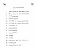
RELAY NOMENCLATURE INDEX
ANN
Annunciator--provides control for bell and light for
highway crossing gateman.
A
Approach--detects the approach of a train.
AE
Approach Light--provides signal lighting when a train
is approaching.
AS
Approach Stick--provides the time locking in the
switch locking circuit.
ASPS -
Approach Stick--repeater stick of AS and direct repeater.
Repeater Stick of RP, used to prevent as cascading.
ASPSTP - Approach Stick Repeater Stick--repeater of ASPS and T
to Track Repeater. Provides additional contact.
ASPO -
Approach Stick--prevents AS from picking up without
timing Power Off when A-C power comes on after power
interruption.
ASPOP - Repeater of ASPO.
BK
Block Indication--indicates the presence of a train
in the block.
D
Distant--provides green signal control
DS
Directional Stick--operates for a train movement in a
particular direction.
(_._letter denotes direction
such as "E" for East.)
EO
Light Flasher--provides flashing light control.
ES
East Stick--provides detection of an eastbound route.
EXP
Repeater of ES.
EXS
East crossing stick--provides release of crossing
equipment behind Eastbound train.
NABCCJ
WABCCl
~
~
Relay Nomenclature Index cont'd.
G
- Signal--signal control.
GP
- Repeater of "G" or signal green repeater.
GZ
- Signal Control--controlled by a control machine
signal lever.
GZP
- Repeater of GZ
GZS
- Signal Control Stick--controlled by mechanical
lever and control machine lever. Stick circuit
maintains relay energized regardless of position
of mechanical lever.
GZBP - Back contact repeater of GZ for additional contacts.
H
- Home provides yellow signal control.
HG
- Home Signal--provides yellow control for colorlight
signal
HGP
- Repeater of HG.
HGBPS- Home Signal Back Repeater Stick--provides control
machine signal clear indication light.
L
- Lock--provides route locking for a switch.
LBP
- Back contact repeater of "L".
LS
- Lock Stick--prevents switch operation when route is
locked.
LSBP - Back contact repeater of LS.
LK
- Lock Indication--provides control machine switch
locked indication light and prevents preconditioning
of switch lever.
LO
- Light Out--detects burned out signal lamp.
MC
- Maintainer Call--control for maintainer call horn.
MCP
- Repeater of MC.
MCPP - Repeater of MCP.
WABCO
WABCC
""V"~
""V".A./"
Relay Nomenclature Index cont'd.
NWC
Normal Switch Correspondence--indicates that switch
point and WZ are in normal position.
NWCP -
Repater of NWC.
NWCPP-
Repeater of NWCP.
NWCPPP- Repeater of NWCPP.
NWZ
Normal Repeater of WZ.
NWZP -
Second Normal Repeater of WZ.
NLP
Normal Lever Repeater--repeater of normal position
of control machine lever.
NS
North Stick--provides detection of a northbound route.
NWLP -
Normal Switch Lock Repeater--repeats the normal
position of a switch circuit controller and electric
switch lock.
PBS
Pushbutton Stick--energized by a pushbutton and
remains energized after pushbutton returns normal.
PO
Power Off--transfers power from A-C to D-C when
A-C power is off. Control power off indication for CTC.
POP
Repeater of PO.
RWC
Reverse Switch Correspondence--indicates that switch
points and WZ are in the reverse position.
RWCP -
Repeater of RWC.
RWCPP-
Repeater of RWCP.
RWZ
Reverse repeater of
RR
Route Request Relay
RLP
Reverse Lever Repeater--repeater of reverse position
of control machine lever.
RPR
Route Repeater Relay.
wz.
WABCO
~
Relay Nomenclature Index cont'd.
S
Stick--provides detection of a southbound route.
( letter denotes direction such as nE" for East.)
T
Track--detects presence of a train on a section of
track.
TP
Repeater of T.
TPP
Repeater of TP.
TPPP -
Repeater of TPP.
TE
Time Element--provides time delay.
TPS
Track Repeater Stick--energized by "T" and a control
machine lever contact, will be deenergized by the
"T" only.
TEP
Repeater of TE.
TPSP -
Repeater of TPS.
WS
West Stick--provides detection of a westbound route.
WSP
Repeater of WS.
WZ
Switch Control--positioned normal or reverse in
response to a control machine switch lever.
WL
Switch Lock--control for electric switch lock.
WLA
Switch Lock Approach--provides release for WL.
WXS
West Crossing Stick--provides release of highway
crossing behind a train for a westbound move.
XA
Crossing Approach--detects the approach of a train
to a highway crossing.
XTP
Crossing Track Repeater--highway crossing control.
XGN
Crossing Gate Normal--detects highway crossing gates
in the normal position (Raised}.
WABCO
~
Relay Nomenclature cont'd.
XGR
Crossing Gate Reverse--detects highway crossing gate
in the reverse position (lowered).
XGNP -
Repeater of XGN.
XS
Audible Indication--provides control for bell.
XTS
Crossing Track Stick Relay used at the trap circuit
locations.
XS
Crossing stick relay picks up when train occupies
the approach trap circuits location.
XSPO -
Crossing Stick Power Off Relay.
XSPOP-
Repeater of the XSPO.
YP
Yellow Repeater--repeats yellow position of the signal.
YGP
Yellow Green Repeater--repeats yellow or green
position of the signal.
YGPP -
Repeater of YGP.
z
Function Control--operates in response to a control
machine lever.
WABCC
WABCC
~
~
MISCELLANEOUS NOMENCLATURE
B
Number indicates pos. nominal value DC voltage.
N
Number indicates neg. nominal value DC voltage.
EB
Positive lamp energy
EN
Negative lamp energy
BX
A.C. Energy, pos. # indicates nominal voltage
NX
A.C. Energy, neg. # indicates nominal voltage
RB
Positive Track Relay
RN
Negative Track Relay
TB
Positive Track Feed
TN
Negative Track Feed
TEL-1 - Telephone
TEL-2 - Telephone
MEB
Machine Battery (Mach. Light
Battery Pos.?)
MEN
Machine Negative
CEB
Machine coded positive enerty
BlO-L
Line Battery Pos. Energy# indicates nominal volt.
NlO-L
Line Battery Neg. Energy
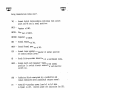
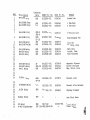
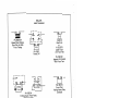
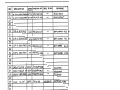
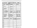
Ref.
Description
Contacts
Data
WABCO Pc. No.
Base Pc. No.
Remarks
PN-150B Relay
6FB
N322500-701
N334266
Biased Line
4
PN-lSOBTR Relay
PN-150BTR Relay
6FB
6FB
N322501-701
N322501-701
N334266
N334266
1 Ohm Track
4 Ohm Track
5
6
7
PN-lSOBD Relay
N322504-701
N335727
3-Position Line
8
PN-150BH Relay
N322511-002
N349904
High Dropaway Trk
9
PN-150BL Relay
PN-150BSR Relay
3FB-N
3FB-R
lFBlF-lB
3FB
6FB
N322510-001
N322503-701
N344874
N334266
Light Out
Slow Drop, Line
PN-150HD Relay
PN-150N Relay
PN-150P Relay
6FB
6FB
2FB
N322505-002
N322502-701
N322508-002
N334266
N334266
N341626
Heavy Duty
Neutral, Line
Power Transfer
PN-150BM Relay
PN-150SO Relay
PP-151 Relay
2F
lFB-lB
GNR
N322517-001
N322512-001
N322516-001
N376048
N372344
N341785
Magnetic Blowout
Switch Overload
Mag. Stick, Line
PN-250B Relay
6FB6F-3B
N322554-701
N373979
Biased, Line
PN-258BSR Relay
6FB
N322551-702
N349769
Biased, Slow Release
PF-256 Relay
4NR
N322561-701
N384243
Highway Flasher
Midtex Relay
4FB
J
J
Non-Vital Mach.
KP Relay
W-400 Transformer
4NR
N217122
18V lOA N451428-0106
X253139-001
Final Stick
Power Trans.
1
2
3
10
11
12
13
14
15
16
17
18
19
20
21
22
23
24
25
26
27
28
29
30
31
32
33
34
35
~I
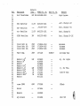
Contacts
Data
Ref.
Description
36
37
38
39
40
41
42
43
44
45
46
47
48
49
50
51
52
53
54
55
56
57
58
59
60
61
62
63
64
65
66
67
68
69
70
71
72
73
74
75
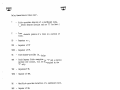
W-400 Transformer
18V 20A N451428-0109
--
High Current
CCR-4 Rectifier
13.SV
N451372-0101
--
Batt. Charge 4-6C
CCR-5 Rectifier
3.0V
N451372-0l04
--
Batt. Charge l-2C
CCR-A Rectifier
13.SV
N451372-1301
--
Batt. Charge 6C
CCRP-6 Rectifier
30V
N451372-0905
--
Batt. Charge 10-13C
Circuit Brkr 6A
Circuit Brkr lOA
Circuit Brkr 15A
250V
250V
250V
J725694-0034.
J725694-0035
J725694-0036
--
Heineman
Heineman
Heineman
Fuse 10 Amp.
250V
J071120
Resistor
Resistor
Resistor
Resistor
Resistor
Resistor
Resistor
Resistor
Resistor
12W
Nl56683
Nl89956
Nl56682
N239433
Nl56681
J721587
J721161
J073841
N331321
--
Adj. for lights
--
Adj. for Trks.
--
Fixed KP Snub
--
KP Snub
--
Shunt SOV
--
4.Sw
SOW
lOOw
1.2w
150w
200w
3000w
12W
2W
2W
SW
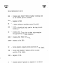
WABCO Pc. No.
Diode 1N4005
600V
J723568
Switch
----
J072616
Rheostat
Lgt Arrestor
Base Pc. No.
--
-N238637
Remarks
Cartridge Type
J620826
N314266
~,
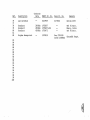
Ref.
Description
76
77
78
79
80
81
82
Lgt Arrestor
Contacts
Data
WABCO Pc. No.
Base Pc. No.
--
N327989
Nl70501
Sonalert
Sona le rt
Son alert
2900Hz
2900Hz
4500Hz
J705057
J705057-001
J792472
Duplex Receptical
--
J072030
----
Box J700245
Cover J069834
-Remarks
Series 400V
Trk #1 Entr.
Emerg. Indic.
Trk #2 Entr.
Grounded Recpt.
83
84
85
86
87
88
89
90
91
92
93
94
95
96
97
98
99
100
~I
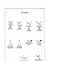
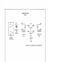
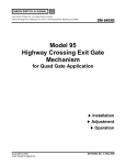
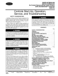
RELAYS
DIRECT CURRENT
\
I
r-----,
-----=--e•T1
1
~
- --T2
PP-151 Magnetic
L
:
-A _.J
---+
____
+B_. ----+ ._-_B_ _
Stick Relay
+A
PN-150 BL
Light Out Relay
3FB Double Coil
r- - - - I
e+T
I
0
+T
1F
-A
I
I
---+
PN-150 BO
3 Position Relay
With Front Test
---,.. ~-..;:B:...+-
PN-250 B
Biased Line
With Front Test
L------'
PN-150 SO
DC Switch Overload
Magnetic Stick
Biased
KP Relay
Midtex Relay
RELAYS
DIRECT CURRENT
,_.,i-A
r-----,
+Tl
~---,11--A•~+
A~--~~,~1
c- I
1
PN-258 BSR
Biased Slow Release
Slow Pick Up With
Front Testing
I C+
1..-- -
-
_...J
PN-150 P
Power Off
+Ai f-A
1---.1
PN-150 B
Biased Line
or
PN-150 BTR
Biased Track
With Front Test
PN-150 BM
Magnetic HD Contact
With Front Test
r------.,
I
e+T
I
L
+Al I-A
I
I
I I
J
PN-150 BH
Hi Drop Away Track Relay
With Front Test
(Coils in Multiple)
(Coils in Series)
+Al !-A
I I
F
PF-256
Flasher Relay
+Tl I-A
1--.1
PN-150 BH
-006
With Front Test
PN-150 HD
Front Test
Having Heavy Duty
Contacts
+Al
,____.,I-A
+Al I-A
PN-150 BSR
Slow Drop Away
With Front Test
PN-150 N
Neutral With
Front Test
I I
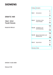
RELAY CONTACT ASSIGNMENT
MIDTEX
Base Contact Assignment
\
\
..!..
2
_§_
~
13
3
°"
..1_
Note: Deenergized Position
Of Biased Relay Is With
Armature Counterclockwise,
Making Revene Contacts.
14
Keying Stud
Biased
;\\. Relay
~~~!J
9
10
Contact Positions and Contact
Symbols for KP Relays
11
,
Magnetic Stick
;: ~ Relay
12
Contact Numbering
Viewed From Front
~
Relay Contact Assignment
Frant & Back Contact Assignment
Are Per Following Table
HEEL
FRONT
BACK
9
10
11
12
5
6
2
7
8
1
3
4
Number "X" Designates Contact
Assignment
Example:
~
Contact No. 1 Implies
the Heel Is 1H; Front 1 F;
the Back 18.
RELAY CONTACTS
~
Front Contact
Closed
(Relay
Energized)
]_
Polar Contact
(Closed Normal)
._LJ
~
Front Contact
Open
(Relay
De-energized)
Back Contact
Open
(Relay
Energized)
Back Contact
Closed
(Relay
De-energized)
..__r•
l
Magnetic Blowout
Contact
High Current
Contact
Polar Contact
(Closed Reverse)
~
l
t
Checking Contact
Of Thermal Relay
---u
l
'L
Constantly Moving
Contact
•
Contacts Of
Same Relay
~
~
Style U5 Switch Circuit Controller
Contacts Closed With Switch Reverse
Contacts Should Be Adjusted To
Operate When Switch Point Is %.
From Normal Position.
~
L_
Starting Button
Contact
(Normally Open)
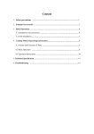
RECTIFIERS
Suffix
0101 CCR-4
0104-CCR-5
1301- CCR-A
Suffix
I
/
* Select Terminals Per Application Requirements
+1PBr--CQ±----i
*+~~4P
-DC
Circuit Symbol
I
L- - - - - - -
• Select Terminals Per Application Requirements
+1PBr--rQj+3P
2P
4P
!_ _______ J
J +DC
CORRECTIONS: AC LINE TO +1 P & 4P
FOR 120V JUMPER +1P TO +3P,
2P TO 4P
FOR 240V JUMPER +3P TO 2P
DIFFERENCE BETWEEN CCR & CCR-A
CCR - provides full-wave rectification & efficient
current regulation for battery charging·service.
Charging current is available from Oto maximum
rated output with two-rate charge capability.
CCR-A - is a self contained full-wave rectifier
designed for automatic battery charging service.
It has an adjustable high rate & an adjustable
low rate of charge & automatically cycles between the two rates. CCR-A contains a solid
state control circuit for automatic monitoring
of the output voltage and automatic battery
charging rate adjustment.
The low charging rate is determined by an external resistor connected across R R .
1 2
Suffix - 0905
Circuit Symbol
* ~--i
~
-DC
AC~I
AC
!_ ___15_
I
_ _ _
+DC
* Select transformer leads per application requiements.
Tape unused leads separately with 3/4 black friction
tape (A77358). Tie securely to transformer with all
marking visable.
'
-OC
I
+DC
Circuit Symbol
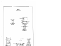
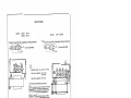
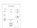
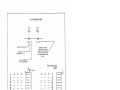
M23-A SWITCH MACHINE
\
\
Motor
MOTOR TERMINAL BOARD
Note: I\Jumber in circle represents number of terminal.
Number not ,n circle shows number of terminal
to which other end of wire is connected.
FIELD
MOTOR COMPAIHMENT
Hf ATER !WHEN USED)
r---~....;.....................,ll"'"'~"'
~
MAIN TERMINAL BOAR
y
0
38
@
©
@
®
@
8
0
0
23 19
CIRCUIT
CONTROLLER
HEATER
(WHEN USED)
21
©
17
CONTACTS
CONTROLLED BY
SELECTOR LEVER
0
37
SHUNTING STRIP
p
14
© 0 © © ®
20 18
@
22
@
§)
52
16
26
5~
.___ _-<51
Wiring Diagram For Standard
o,c.
DIRECTION
OF NEXT
·-'-1-----L ROTATION
31
High,voltage Switch Machine With Split Field Motor.
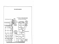
TRANSFORMER FACEPLATE$
TRANSFORMERS
TI
-----,
A*
SUFFIX -
SUFFIX -
style w-400
240t228v 60/100hz va.360
+1P2P
3P
q_ m.Y•.
_)<.1i_v9
Z* J
t...::3P_______
2 secondaries 18v·10a
'1A
18
1C
10
(JUMPER "D" TO "W"I
Q~_3yQJ
..9yo2a~
main seco:::rary
1
• SELECT TERMINALS PER
APPLICATION
0109
0106
I
oi£y
wq1~ lY.~lz
'.5 .112v
,.ft
..,A
20
QpQ.-i;QyQJ.:~P
iffa
secon....ry
w
2
1n"g"'se
28
2C
~I'
,n
2x
2Y("'\ 2Z("'\
1.1JvXQ.~
t1ng "secoiiilary
~ I~
adjustable additively in
0.37v steos
1
240/228: ~&1~0h;~a.360
+1P
2P
3P
Q.. _2_2!L .)<m.9
WABCO
ncondary 18v-20a
+A
B
C
O
+W
X
Y
Z
~~:&<.titv><a@P
Q,J§-b<i~~
adjustable additively in
0.37v steps
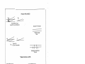
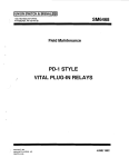
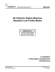
GRAPHIC SYMBOLS
SIGNALS
Automatic
Controlled
t
HIGH SIGNALS
r
{Yellow)
Non-automatic
DWARF SIGNALS
SIGNAL POLE
EQUIPMENT
r
Horn
Green
.-- Yellow
IL_ - Red
I
Fixed Red
SIGNAL OPERA TING CHARACTERISTICS
HIGHWAY CROSSING WARNING
EQUIPMENT
1
Automatic
±
Phone
rp
Lights ..-
Route Sign
l--r----;,;;Oii,110 -
Lights
""Gate
Symbol indicates stick control of signal; restoring of controlling lever to
normal position is required before signal can again be cleared for a following
train.
Symbol indicates non-stick control of signal, restoring of controlling lever to
normal position is not required before signal can again be cleared for a
following train.
TRACK APPLIANCES
Style M23-A Power
Switch & Lock Movement
RAILWAY TRACKS
1.0 Meter Gauge
Track
+_
·~
Style U5
Switch Circuit Controller
1
I I1
Bootleg Connections
To Rail
INSULATED RAIL JOINTS
Track Circuits
In Both Directions
Track Circuit On Left
None On Right
Track Circuit On Right
None On Left
f
Insulated Switch Rod
:::::-E
Track Circuit Bond
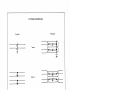
SWITCHES
SINGLE LINE PLAN
Set For Straight Track
Set For Turnout
/
/
DOUBLE LINE PLAN
~
(Interlocked)
Set For Turnout
(Interlocked)
Set For Straight Track
(Non Interlocked)
Set For Turnout
(Non Interlocked)
Set For Straight Track
Power Switch
6-<>
Controlled Switch Lock
Dual Control Machine
BUILDINGS
Operator Facing Track
Control Point
_O
Relay Case
Stations & Other Buildings
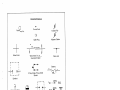
MISCELLANEOUS APPARATUS
RESISTORS
CAPACITORS
DIODES
( Rectifier)
/ II
/
---/\,/\/\_.-
Fixed
•
Fixed
•
+ ~
Fixed
~
Tapped
~
Variable Resistor
Or Rehostat
•
~I
•I•
Voltage Limiter
•
•
e
Suppressor
Lamp
l:::::j
Capacitor Unit
••
Terminal Strap
r------,
I
I
LINE
I
I
I
1
2
•
I
•
90
I
I LOAD
I
I
2 I
L _ _ _ _ _ ...J
Dual Circuit Breaker
Fuse
00
•
Single Circuit Breaker
•
Utility Box
Dual Outlet
DRAWING SYMBOLS
f
•
0
Terminal Point
Twisted Pair
Reference No.
~
Adjacent Cables
Cable Plug
+
WITHIN HOUSING
Wires Cross
r-----,
I
c
I
I
•et--...---
I •
1 +
Wires Join
Wires Enter Or Leave
Housing Or Cabin
I
Battery
~1 ec• •1-=-
2 Pole, Single Throw Knife
Switch
L----_J
eoAH
Sonalert
r----,
l
~
Ground Symbol
Closed
In Power Position
I
I
I
e
e
I
I
1
2
I
'----...l
Dimmer
""ac
NOMINAL
=
l~I
CELLS
NOMINAL
80AH l~I
H-2
Searchlight Signal Operating Mechanism
~rt
~~
R-G
R-Y
Contacts On Searchlight Signal Mechanism
Y = Yellow (Contact Closed When Signal Displays Yellow Aspect)
G = Green (Contact Closed When Signal Displays Green Aspect)
R-G
= Red-Green
R-Y
= Red-Yellow
(Contact Closed When Signal Displays
Red Or Green Aspect)
(Contact Closed When Signal Displays
Red Or Yellow Aspect)
AMPERE
HRS.
LIGHTNING ARRESTERS
Physical
Symbol
Series
Shunt
Series-Shunt
PLUG CONNECTORS
RACK
RACK
R1
R2
,-r
-r
-->>>----~--K-/
R2 111 7
CABLE OESTINA1'0N
J 1
R1 111 7
IDENTIFICATION
ASSIGNED TO MALE
CONNECTOR MOUNTED
IN RACK 2 AND CABLE
END TERMINATING IN
RACK 2
CABLE NO.
BETWEEN Rl · R2
CABLE CONNECTOR
PIN ASSIGNMENT
Relay Rack Fixed
(Male}
1
CABLE
1
1
2
3
2.JL
E..
17
~
~
~
30
..ll
4
-...!..
..ll.
3
2
_1_
•••
• •••
••••
• •••
_§_
••••
••••
••••
••••
••••
••••
••••
.JL
..ll.
..1L
• •••
••••
• •••
••••
•• • •
_gi
.M.
~
•• • •
Cable Connector
Pin Assignment (Female)
Control Consol Fixed
(Male}
A
~
li
.!L
.ll..
.JL
...!_
_1_
.L
_L
~
1
••••
••••
••••
•• • •
•• ••
••• •
••• •
••••
•••
PUSH BUTTON CONTROLLERS
C
~ SWITCH LEVER BANDS OF
~CONTACTS MADE
NORMAL
A
1
---©---MADE REVERSE
2
1 NML Open
1 NML Closed
UN374214
Push 2 Pos. Stick
Rear View
c
SIGNAL BANDS OR CONTACTS OR P/B TURN
CONTACTS
N · NORMAL POSITION
"X" · DIRECTION OF
TURN RT/LEFT
LEGEND
A
----t •-
1
-
i
- 2
2
Contacts
Are Stacked
Rear View
c
A
.1.
.1.
- --
-
.l
.1
.l
- .!!.
- .!
11
11.
B
~
A4
Contacts
Are Stacked
A7
Rear View
N380619
1 Nor. Open - Push
2 Nor. Closed, 3 Nor. Open
Or C to R
UN 380619
CL/CR
PUSH TURN
A1
A2
C2
UN380618
1 NMLOpen 1 NMLClosed
PUSH PULL ONLY
A2
.!.
C1
1
1
~
®
qs
A3
C2
A1
AS
C4
A8
C7
A6
C1
©
cs
~
ca
C6
C to L
C to R
C to L
~
C3
r·,
••
82
* Rt. stack ,s not
affected by left
turn ... vice versa
PUSH BUTTONS
CONT.
1
2
.l..
4
~
6
Contact
Numbering
i
Contacts
Are
Stacked
:1
N382242
A3
PB
AS
I
J
A2
A6
A1
I
1
E
N382229
Right Turn
Only
Left Turn
Only
Common
To
Both
Push/Pull; Turn Right Or Left No Push/Pull
REF
I
~ WABCO PC. HO.
J>fSC Al PT/ON
Pll·ISOS
DATA
"r:8
R.ELA"I
~32.2.60f>•7t::>/
BIISE PC.No.
..
l<Elilll'I ~ IC.S
/1133+2'-'
8JA6EDLJNE
.:
..
2.
3
f'N-/SoBTR. RE.l.A'f
~FB N321.5()1 ... 10I
N331-2,r.
:J. <IHM
TRl1Clt..
4-
PN-JSoBTR. RELAY
<-ra N3z Z.5tJ I -70/
N33<!-2~G.
4f.
Tl!ACI(
OHM
s
'
7.
PN-ISOBb REL/4"(
..3FB-N
3Fa-R.
}137-1.,504-10/
/tl.3357'2. 7
3 - Pos, no/fl L/11/e
8
P 11-150'8>-I R.E.L.A'I.
lf:8·
11:· 1B
N32'ZSl/-ooz.
N'3ff,a+
f/14111>£of>AWA'I T~K
't
3F&
N.32ZS/0 •00 I
/0
PN-1so-e1...· PctA'f
P N • /SO B.S 2. f.EL.A 'I
e.Fa
N32.,z.50 3 -70 I
N3+i-874
N33'f-2'-'
.SLIJW "J)j!t,p I LIN~
/2
PN -ISoJ.ll> ~£1..A'f
,i:e
N32-ZSt:J5·doz.
11334-z,,
HEAVY "b~TY.
13
11-
PN-JSON
/<El. A'f
,Fs
N32Z.SOZ--70/
N3s+z.e-t,,
NEUTIU41. 1 LJN£
PN-/SOP
fe.E'-"l'f
2.F.B
N32.Z.So8 -002.
#3.,./
/>C~E I!. TRAN.S'J:E It.
11322.5 I 7-0o I
N37,o4-6
N:3723"1-+
,,
'
IS
"24
I.tr.Hr o
vr
.
/(.
/7.
JS
P>J-
/f
PtJ-/6'0 So ~EI..AY IF'B· /B /(322S /2-00/
ZD
PP-/51
'fl.1:Lll'f
P/./-2.508
R.ELA'1
ISO 'JJm !?Et.A'f
ZF
,wR
N322 s11o-oo/
/t/3+1786
/1111~/./GTIC B/.OWOtJT
SIAJ l"T<! 1-1
Ot/£.R.LOIJ'/)_
lf)A(j 1 $TIC.I<., t..lAIE
21
2,?.
z~
Z4
Z.5
2,
PN-258~R. RELA'f
4F8-
'-C'-38 N32Z..SS4-701
,rn
!JASE"/J,,
N373 C/7'1
i.JN£
..
N3'-2.SSJ-7o~
N34'1711'1
/JJA<JED, Stow R£VJIS".,;
N 3 8.,Z4'3
Hl4HWA Y FU!IIGA
27
~e PF-ZGG.
2,
3o
'
31
~EI.Ay
/YJ11)TEX ~rt.;,y
41"~ N3 2'2,S~l-?OJ
1-FB 372 '- 15.3-tk)S.3 3'1ZS8""
lt/()1/-Vl'rAI. /Y)~eN.
32.
3'3
3+ . KP
·._ ;....-
l<&J..A'f
"f.N~
N2li IZ'l.
X2 5 313 9-001 F"INAl- S-7'1 C-1<
I WABCO
. ·. .
.
~·.·.
»ATE i: 3-/f·J.
- ..
..
: (;Fm
AR.ti,ENTIIIII
aoua..oqt,1,:
Fa
II.WY
VILLA ~OSA SH
MATERIAL TA8
30
REF
CONme:TS WABCO PC,.
J>fSC A.I PTION
>i'ITA
35
w-+o O
3'-
'rJ -4 00 7~/INSFOR!YJEI<.
TR.II N $/:"61?/nE,. /.tJV IOJ1
NO.
Ni-'5142t!,-01ot;
l8V ZOA N4s142.a- olt>Cf
BIISE pe.No,
-
ll
R.E /JI llJ J! /CS
·,
POWE/t TRANS
Htt;II Ct/R.R£fi/T
37
38
3'1
10
CC.f?_-4
RECTlrlcR..
/3,SV N+Sl.372-0/0/
4-1.
/
/
4-z
CC. fZ. - 5 RE c T 1 /:'"1 E /(
4-3
44
cc R.-A
3,01/ N<r.Sl37-Z.-OI04-
ReC.T lrl£R
/3,SV
//4'-51312-/301
45
4,
3oV N4-5 l37 2 -0905
~CRP-" {<£CTIF/c~
-
-
BA rr. a HltR<.G
4-, a
'Blirr; ~Jtllli~ E /-2e_
/ill rT, ~IIA~lf
~t! LA
"BArrtJIAR4f
/d-/3(!.
47
48
4-C/
,n
Eo
2S"OV 3°7 Z Sto'lf-003A
C'.!R.Cvrr B RKR
51 C 1/?.CIJ IT /31!,.J(./< IOA 2501/ J'1ZS""1+-tJ035
52. a11<au1r E/cJ<.tJ.. /SA 2.t:OV j1zs,94--ooa,
-
--
l1£1AIEMAN
/.lliJNEl'IA II
H£1/JEHIA/J
£"3
St
.ss
J:'VSc
250"/
Jo Am/J
J07/l20
s,
57
SB
RESJSTl'l(<
4-,5w
/!.E. s, s ro R.
So"-'
f,I
S9
Rcs,sroR
~o
~ESISroR
/oo 1~ 1
N1sc.,a2
N 2,.:.314-SS
''
,2.
,3
,1,E.
R.ESISTo(<.
/,zw
12.W
~ES.IS 7't) A.
JSow
2.W
J72tS87
RESISTof<.
2oow
2W
~~1$,()R '3ooow
RE, 1.$,o R.
SW
'J7z11~1
::fo73g4-1
,,
,-,
,a
12. vJ
NIS'1~83
J 8'19 Sf.o
J../JS,6,8 I
A/33/32/
/JZ'38'137
e.ART{(/<l,E 'T'fPc
-
I/DJ', F'btt. t141-1 rs
-
A D1. Foll i!e.KS.
-
-
-
--
FIX£ P
KP
SfJv/3
.
--(WABCO
l>IITE ~~-/f-'78
- . : <;FM
/ltP.r.ENTINlf RWY
80ULO<i#I£ ro VILI.II ROSA
MATERIAL TAB
SH 3l
~
L~
REF
'-tf
])fSC RI PTION
,:OHTAC:1$
':D,47"Jtr
,ao v
IN'I-OOS
J)I01>E
WABCO Pt:., HO.
J723568
SRSE pC.IJo,
-
••
R.E /JI /If J! ltS
J</J S/IIUB
70
sw,rci,t
-
JD7 z.t.
73
1t-
RJ..J£.oSTAr
-
.T, 2.osz..,
-,5
LG,.,- ARR. E;STO ~
71
7'!-
.,,
-
t..~ T A Ke.E. ~TOI<.
I{.
N:1// i- z Go~
A/32.7989
-
-
/',l/7050/
'
s )./ {)"' .,-
SOI/
S£f<IES
4oov
7?
78
7'1
8"
$ONAl.cRT
2'tOO/f2.
So Al A,.£ a-r
SoN4L€R,
·2.etoo Ha J70SOs7·00I
i-500/.I~
:[792472
-
J072.050
81
sz.
1:>u Pt..e
j7050.57
x 1<cc.cPT1t11L
8"3
-
aol< ::,,oo z+£
<!OI/ER:rot..9 8.3+
7"/?J< ' I
£NrR.
J!:P'JE.l<t;, //11.J:Uc,
TR.~ .. Z.
£Nr~.
t;ROUN1>E1J ~l:C/>r
2,4-
8.5
S6
97
.
ea
8'1
'/0
q/
fl
93
94
95
96
'17
98
99
.
/00
....
·-
I WABCO
.
»ATE i: 1-/1-78
- .
: t;r/11
AR.G,ENTINII RWY
BOULO<;HE ,._ VII.LA ROS/i SI-(
MATERIAL TAB
~
32..
-
/
/
/