1
WABCO
~
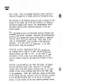
SERVICE MANUAL 6071
TYPE "EL" THREE INDICATION CODED
CONTINUOUS CAB SIGNAL
AND
SS-3 OVERSPEED PROTECTION
OPERATION AND MAINTENANCE
August, 1979
B-79-75-2146-2
UNION SWITCH & SIGNAL DIVISION
AMERICAN STANDARD, INC.
Swissvale. PA 15218
...
WAS CC
'V'~
TABLE OF CONTENTS
SECTION
I
II
III
IV
v
...
VI
VII
VIII
IX
x
XI
PAGE
GENERAL DESCRIPTION
THEORY OF OPERATION
CAB SIGNAL INDICATIONS
WAYSIDE CONTROL OF CODED RAIL CURRENT
WAYSIDE CONTROL OF CUT IN/CUT OUT
AND RUNNING TEST LOOPS
DESCRIPTION AND LOCATION OF ONBOARD
EQUIPMENT
CIRCUIT OPERATION OF ONBOARD EQUIPMENT
MAINTE.NANCE AND TESTING OF ONBOARD
EQUIPMENT
MAINTENANCE AND TESTING OF ONBOARD
OVERSPEED EQUIPMENT
PARTS LIST AND ORDERING INFORMATION
EQUIPMENT REFERENCES OF EL CAB
SIGNAL SYSTEM
i
1
1
2
4
5
5
9
13
15
19
20
WASCD
~
LIST OF ILLUSTRATIONS
Figure
Page
1
Wayside and Cab Signal Aspect Diagram
3
2
Typical EL Cab Signal System Receiver Set Up
6
3
EL Cab Signal Speed Control System Block
Diagram
11
Three Indication Speed Control Locomotives and MU Cars Relay Operation
18
5.lA
EL Cab Signal System Receiver Diagram
21/22
5.lB
EL Cab Signal System Receiver Diagram
23/24
6.lA
Type EL Cab Signal and Overspeed Standard
Circuits (EX MU Cars)
25/26
Type EL Cab Signal and Overspeed Standard
Circuits (EX MU Cars)
27/28
Type EL Cab Signal and Overspeed Standard
Circuits (EX MU Cars)
29/30
Type EL Cab Signal and Overspeed Standard
Circuits (Chopper Cars)
31/32
Type EL Cab Signal and Overspeed Standard
Circuits (Chopper Cars)
33/34
Type EL Cab Signal and Overspeed Standard
Circuits (Chopper Cars)
35/36
Type EL Cab Signal and Overspeed Standard
Circuits (Diesel 3700)
37/38
Type EL Cab Signal and Overspeed Standard
Circuits (Diesel 3700)
39/40
Type EL Cab Signal and Overspeed Standard
Circuits (Diesel 3700)
41/42
Type EL Cab Signal and Overspeed Standard
Circuits (Diesel 2000 Series)
43/44
Type EL Cab Signal and Overspeed Standard
Circuits (Diesel 2000 Series)
45/46
Type EL Cab Signal and Overspeed Standard
Circuits (Diesel 2000 Series)
47/48
4
6.lB
6.lc
6.2A
6.2B
6.2C
6.3A
6.3B
6. 3C
6.4A
6.4B
6.4C
ii
WABCCJ
'V"A:..'V'
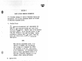
SECTION I
GENERAL DESCRIPTION
The Coded Continuous Cab Signal System was developed to
provide in the cab of the locomotive, a signal that is always
plainly visible to the engineman, and which at all times
shows the conditions ahead and promptly indicates any changes
in those conditions.
Means are provided for automatically sounding a warning
whistle after a more restrictive cab signal indication is
given and for silencing this whistle by operation of an
acknowledging switch.
SECTION II
THEORY OF OPERATION
2.1
GENERAL THEORY
The system employs alternating current at a frequency of 90
or 60 hertz per second, fed into the rails at the exit end
of the track circuit, as the medium for continuously transmitting indications of trackway conditions to the moving
train. This AC track circuit current is the trackway element
of the system.
The two proceeding cab signal indications are obtained by
interrupting this alternating current at regular intervals,
each proceed indication having its own distinctive "code"
or rate of interruption. These "codes" may be measured
by their number of interruptions per minute, and the values
employed are as follows:
Cab Signal Indication
Code
180 per minute
VMA
VL
75 per minute
No Code
VR
SV (Overspeed)
The VR indication (the most restrictive indication of the
system) is obtained not only when the AC track circuit
current is cut off, but also in any track circuit in which
the alternating current is steady in value and is not
interrupted at a code rate.
The system inherently provides immunity from interference
of an unsafe character by foreign current because the enginecarried apparatus is designed to respond selectively to the
alternating track current periodically interrupted at the
code frequencies and to this character of current only.
6071, p. 1
WABCCI
~
Voltages of the same frequency and code rate as the rail
current are induced in receiver coils carried on the
locomotive and these voltages, after being amplified, are
used to operate a code following type relay called the "master"
relay. This relay .in turn governs two decoding units. The
180 decoding unit is responsive to a 180 code rate only, and
the 75 decoding unit is responsive to any code rate. The
associated decoding relays in turn control the cab signals
and the timing valve magnet.
The acknowledging relays are also controlled by the decoding
relays in such a manner as to require the engineman to
"acknowledge" a change in the cab signal indication when the
change is to a more restrictive indication.
SECTION III
CAB SIGNAL INDICATIONS
The primary source of speed information is the wayside equipment, and its purpose is to define the stop points and code
change points along the track. The cab signal conveys to
the engineman, in advance, the condition of the traffic in
the area he is approaching.
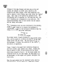
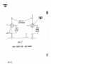
Figure 1 shows how the speed limit indication changes as
one train closes in upon another train ahead. Assume that
Train B enters the first of four blocks with the fourth
block being occupied by Train A. As the engine passes the
insulated joints, CC, for code change, the VMA aspect will
be maintained, and this aspect will persist throughout the
first block.
When the engine passes over the insulated joints entering
the second block, the cab aspect will immediately change
from VMA to limited speed and the warning whistle will sound.
The engineman must immediately take steps to bring the train
speed down below the limited speed.
When the engine passes into the third block the cab signal
aspect will change to VR and the train speed must be reduced
below the VR speed. As for the previous code change, the
whistle will again sound and the engineman must operate the
acknowledging switch to silence the whistle. As mentioned
previously, the train must be operated below the VR speed
in such a manner as to be able to stop short of any track
obstruction.
While Figure 1 shows a train closing in on another train, it
should be realized that various wayside conditions will set
up any number of variations of the previous analysis. As
an example, instead of having Train A in Figure 1, we can have
a controlled signal at the cut section between blocks 3 and
4.
If this signal is at VR, Train B would operate as previously
described since a stop is required at about the same point.
The SV (red) lamp is an overspeed indicator and will be illuminated anytime an overspeed condition exists. For further
information on the overspeed see Service Manual 6082 (Overspeed
System and Axle Generator).
6071, p. 2
WABCC
~·~
0
0
0
:t/E-
$\f VR Vl VMA
0
0
0
*
0
SV VR VL VMA
0
0
~
SV VR VL VMA
0
~
0
0
SV VR Vl VMA
cc
0
0
*
cc
cc
cc
cc
cc
cc
0
SV VR Vl VMA
0
0
0
*
SV VR Vl VMA
Figure 1.
Wayside and Cab Signal Aspect Diagram
6071, p. 3
WABCCI
~
SECTION IV
WAYSIDE CONTROL OF CODED RAIL CURRENT
The apparatus used for operation of the Coded Continuous Cab
Signal system consists of two main parts:
1.
2.
Wayside Equipment
Rolling Stock
The main concern with the wayside will be to point out what
must be provided in the track circuits to provide the necessary
information in the cab.
The code transmitter, located in the wayside portion of the
system, is the mechanism which interrupts the flow of AC.
It consists of contacts actuated by an electrically driven
pendulum which is mechanically tuned to the code frequency.
A separate code transmitter is used for each code frequency.
Located at the code change points are the instrument housings.
Inside the housings are relays that continuously detect track
conditions on either side of these locations. Then by proper
circuiting through the various relay contacts, the following
types of energy can be fed into the track rails:
1).
2).
3).
4).
With no train approaching, steady 60 or 90 Hz.energy
is fed into the rails.
With a train approaching a wayside location and the
track conditions ahead permit VMA speed, 60 or 90 Hz.
energy interrupted at a rate of 180 times a minute
will be fed to the rails.
With a train approaching a wayside location and the
track conditions ahead permit operation at VL speed
60 or 90 Hz. energy interrupted at a rate of 75 times
a minute will be fed to the rails.
With a train approaching a wayside location and track
conditions ahead permit operation at VR speed only,
no energy will be fed to the rails. As mentioned
earlier, the rail energy as provided under 2, 3, and 4
above will provide cab signal aspects of VMA, VL and
VR.
When a train enters an occupied track circuit, NO CODE will
be received on the locomotive because the rail current will
be shunted by the wheels and axles of the train ahead.
Likewise, any condition such as broken wire, open or misaligned
switch, or loss of power, or any condition that produces
steady (uncoded) AC rail current, or no rail current will
result in the display of the most restrictive cab signal
indication.
6071, p. 4
WABCD
"V'tA./
SECTION V
WAYSIDE CONTROL OF CUT IN/CUT OUT AND RUNNING TEST LOOPS
At certain locations where trains enter and leave cab signal
territory, test loops have been installed for the purpose
of turning on and turning off the cab signal equipment on the
train.
The cut in/cut out loop serves to turn on the cab signal
equipment by a 60 or 90 Hz.signal coded at the 180 rate when
the train is entering the cab signal territory. When the
train is leaving the cab signal territory, the loop is
energized with a high energy 60 or 90 Hz. signal coded at the
180 rate. This with proper manipulation of the switches
on the lococomotive will cause the cab signal equipment on
the locomotive to be inactive.
When it is desired, that the cab signal equipment be cut out
at locations other than a cut out loop, such can be accomplished
by actuation of the Standing Electric Cut Out (SECO) switch
(both decoding relays must be de-energized). The {SECO) switch
is located outside of the locomotive or car and can be reached
from the ground. This location ensures that the locomotive
or car is not moving when the switch is operated.
SECTION VI
DESCRIPTION AND LOCATION OF ONBOARD EQUIPMENT
The electrical equipment used in the EL Cab Signal System is
shown in schematic circuit form in Figure 6.1 through 6.4.
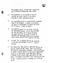
1).
The Track Receiver is the unit by which the control
is transmitted from the rails to the apparatus on
the train. The receiver is made up of a pair of
laminated iron bars on each of which is a molded
coil complete with cable molded as an integral part.
The two coils are connected so that the voltages
induced in them by the rail current are additive.
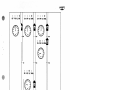
The receiver is mounted ahead of the front truck
and is so located as to have a clearance of from
8" to 12 11 between the bottom of the bars and the
top of the rail and having the center of the coil
mounted directly above the rail.(Figure 2)
2).
The equipment box houses the amplifiers, decoding
units, control relays and main terminal board.
All components of the apparatus are shelf mounted
and the shelf is supported at the top and bottom
on compression-type rubber mountings designed to
afford maximum protection from shock and vibration.
6071, p. 5
WABCD
~
WABCD
~
CIIBLES TO
JUNCTION BOX
MAX 12
4
MAX 12"
NOMI()"
/YJ/N 8
I
NOIYl!O''
11
MIN B''
_jl __ _
PARTNO.l--t
VIEW
t
.C"
NEW CHOPPER CARS - WIDE GAUGE
PARTNtJ.
WABCC
~
Mf/X./2"
NOM./0''
MIN.8 11
MAX.12"
I
~r
NOM./0"
MIN8"
-T-
--~x-
I
II 1f
VIEW
EXISTING
Figure 2.
6071, p. 6
B
DIESELS AND
MU - NARROW GAUGE
Typical EL Cab Signal System Receiver Set-Up
WAEICC
'V",A./
The equipment box is of welded steel construction
and is dirtproof and watertight when closed.
3).
The speedometer is cabin mounted so that its
readings are plainly visible to the vehicle
crew when in their accustomed positions.
4).
The acknowledging switch is located within convenient
reach of the engineman. A change in cab signal
indication is acknowledged by pressing the button
and allowing it to return to normal.
5).
For operation outside of a cab signal territory
the acknowledging switch, cut out relay and EPCO
are used when passing out of signal territory.
The speed control and cab signal is cutout by
operating the acknowledging switch while passing
over a circuit carrying high current at 180 code.
6).
DC Power (32V) is supplied from the F42 Converter
to the cab signal equipment by way of a 64 Volt
battery.
7).
The timing valve, OSRP, which is controlled through contacts of the OSR and OSPP relays, forms a link between
the electrical and pneumatic equipment. When de-energized,
it causes the warning whistle to blow and if appropriate
action is not taken within a specified delay timing of
6 seconds, a train control brake application will take
place. Air pressure is provided to the 6 second delay horn
by way of a reducing valve at a pressu~e o! 3.16 Kg per
sq. cm.
8).
An electronic governor, which has a magnetic pick-up
mounted on the journal box, controls the overspeed
relays, which impose the appropriate speed limit
as required.
9).
A frequency change over switch, located
in the cab, is used to select either the 60 or 90 Hz
amplifier depending on the territory over which
operation is desired.
NOTE:
In some cases the change over switch
directly controls the amplifier selection,
while in other cases the change over switch
controls the FS (Frequency Selection) relay
that in turn selects the amplifier to be
used.
6071, p. 7
WABCD
~
10).
All of the functional elenents -- the amplifiers, the
master relay, the two decoding units, the one PL-59 relay
and the three PN-59 relays -- are separately detachable
by means of plug connector terminal boards. Each unit is
enclosed in a dustproof case equipped with a convenient
handle for removal and carrying of the unit. The amplifier unit and each decoding unit are held in position
by a latch and thurJb screw.
Each PN-59 relay and PL-59 relay is raounted on a base
pernanently attached to the rack in the equipment box and
is held securely in position by hexagonal nuts applied to
the threaded ends of the two guide rods on the mounting
base. These guide rods also serve to align the relay so
that its plug connectors will properly engage the receptacles on the mounting base when the relay is plugged into
position. Each PN-59 relay is identical and, therefore,
completely interchangeable. The PL-59 relay is indexed
by indexing pins so that it cannot be interchanged with
a PN-59 relay.
The GJ relays are front nounted and may easily be
replaced by removal of the two mounting bolts and pulling
off the push-on wire terminals.
The printed circuit boards are plug connected and retained
in their card file by a hold in bar.
6071, p. 8
WABCO
~
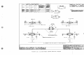
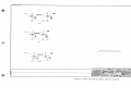
SECTION VII
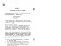
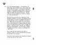
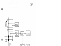
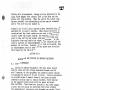
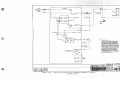
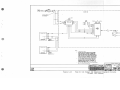
CIRCUIT OPERATION OF ONBOARD EQUIPMENT (Refer to Figure 3)
The input signal for the onboard equipment is picked up from
the rails by two receiver coils that are mounted over the
rails in front of the lead axle. These two coils are connected
in series so that the signals induced into them by the rail
current are additive. A two stage circuit, filter and amplifier
is located between the track receiver and ~he master relay.
This filter (tuned for 60 Hz or 90 Hz) provides the required
rejection of noise that would interfere with the proper
operations of the Cab Signal System.
Following the filter is a Darlington connected pair of
transistors that amplify the output of the filter. The output of this pair is transformer connected to a fullwave
bridge rectifier. The DC from the rectifier bridge is
a pulsed signal that is used to turn on and off alternately
two Darlington pairs so that the current flowing in the master
relay coil reverses in step with the code signal in the
rails.
The master relay is of the DC polarized-stick type, that is,
its armature will be held by the permanent magnet in whichever position it occupied while last energized. With
alternating current of code frequency in its coil, the relay
is energized periodically in opposite directions and, therefore, the contacts move from one position to the other at
the code frequency. The relay thus responds to code
frequency current only when this has a value greater than
a predetermined minimum, and its contacts are thereby held
firmly closed by ther permanent magnet in one position or
the other,· except during reversals of current.
When the master relay is operating, it causes direct current
from the 32 volt supply to flow alternately through one
half or the other half of the primary section of the decoding transformer, causing the magnetic flux of this transformer to alternate in direction of the code frequency and
thereby to deliver alternating current of code frequency
to the decoding circuits.
The output of the decoding transformer (housed in the 75 code
decoding unit) is applied to the 180 decoding unit. The
180 decoding unit is tuned to resonance at 180 code.
It consists of a capacitor in series with the primary winding
of an adjustable air gap reactive transformer having its low
voltage winding connected through a full wave rectifier to
the A decoding relay. The A decoding relay will thus respond
only when the voltage applied to its associated decoding
unit has a frequency of 180 cycles per minute (3 cycles
per second) A secondary winding on the decoding transformer
is connected through a reactor to a rectifier which feeds to
6071, p. 9
WRBCD
~
the L relay. This is an untuned decoding circuit and the L
relay will respond to any coding action by the master relay.
The contacts of the decoding relays are used to supply 32 volt
energy to the proper lamp in the cab indicator, to energize
the whistle magnet and to control the acknowledging relays
and other various control functions required in the cab
signal system.
The acknowledging relays are energized directly whenever the
acknowledging switch is pressed. Releasing the acknowledging
switch will de-energize the relays unless power is supplied
over the stick circuit for each relay. Thus, when in 180
code, no acknowledging relays are held in the energized
position.
In 75 code, the RP is energized.
In no code,
the RP and LP relays are energized.
Since the L relay is energized on both code frequencies,
on a charge from 180 code to 75 code, the cab signal will
change directly from "VMA" to "VL". On 180 code, it does
not matter, if the L relay is up since energy is cut off
from its contact fingers by the open back contacts of the A
relay.
With the..:\. relay picked up, the "VMA" cab signal is lighted
over the following circuit; B32, contact 8-7 on the EPCO
contact 2R-1R on the SECO switch, terminal post 18, #2 front
contact on the A relay, terminal post #23 to the "VMA" lamp
in the speedometer. Under this condition, energy is delivered
to the timing valve B32, contacts A and B of the OSR, contacts
C-D on the OSRP, terminal post 34, 3L and 4L of the SECO
switch, a closed contact on the stop insuring pressure switch,
to the TV Magnet. Return common is through a second contact
on the stop insuring pressure switch.
De-energizing either the OSR or the OSPR relays will deenergize the timing valve. The OSR relay is controlled by
the overspeed detection circuits and the OSPR relay is
controlled by the contacts of the acknowledging relays. On
code change from 180 to 75, the A relay will release and the
L relay will remain energized. The "VL'1 cab signal will then
be lighted by energy from terminal post 18, #2 back of the A
relay, front contact of "L" relay, VL Lamp to C. The circuit
of the VMA cab signal will be broken at the #2 front contact
of the A relay. The OSRP relay circuit will be broken by
the opening of #1 front of the A relay.
De-energizing the OSPR relay breaks the power to the timing
valve and causes the whistle to sound, and if the speed is
below the allowable maximum speed for the "VL" aspect and
acknowledgement is made, the timing valve magnet will be reenergized.
6071, p. 10
WAEICD
~
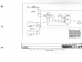
WAYSIDE
EQUIPMENT
FILTER
....---+----1 AMPLIFIER t----::iil'IDECODING
AND
DECODING
RELAYS
CAB SIGNAL
INDICATORS
RECEIVER
WHEELS
&
AXLE
SPEED
SENSOR
SPEED
COMPARISON
AUDIBLE
ALARM
AXLE
DRIVEN
SPEEDOMETER
Figure 3.
BRAKE &
THROTTLE
CONTROL
EL Cab Signal Speed Control System Block Diagram
6071, p. 11
WABCO
~
Acknowledgement applies 32 volt power to the RP relay over
the following path: B32, acknowledging switch in the acknowledge
position, terminal post 27, #1 back contact of relay CO to the
pick-up coil of the RP. Stick energy for the RP relay coil
is supplied from B32, #1 back contact of A, front contact of
RP, stick coil of relay RP to C. When the acknowledging
switch is returned to the normal position, energy for the
timing valve magnet is supplied over the same path as described
earlier for the "VMA" signal. The OSRP being energized from
B32, #1 back of the A relay, #1 front contact of the L
relay, front contact of RP, back contact of LP, terminal post 32,
acknowledging switch to term 29.
NOTE
The speed for "VL" must be below the speed
allowable for that aspect in order that
relay CSR will be energized.
On a code change from 75 to no code, the L relay will release
and the RP relay remains energized. The release of the L
relay breaks the circuit to the timing valve magnet causing
the whistle to blow. The "VR" cab signal will be lighted
over B32, back contacts of A and L relays. VR Lamp to C.
If the speed is below that of a "VR" signal, acknowledgement
can be made. This energizes the LP relay over the back
contacts of the A and L relays. The timing valve magnet
is re-energized and the whistle stops blowing as described
earlier.
A change in code to a less restricting signal, for example
a higher speed limit does not require acknowledgement. Going
to a 75 code from no code will pick the L relay, breaking
the stick circuit to the LP relay. The L relay front
contact Ll, maintains power to the OSPR relay through the
front contact of RP and the back contact of LP. Since the
higher speed limit is not exceeded, the timing valve remains
energized and the whistle does not blow. Similar action
occurs on each upward move, each time de-energizing the
appropriate acknowledging relay.
Operation in non signal territory is accomplished by acknowledging, while passing over the high energy cutout loop
at the end of signal territory. When this is done, the
appropriate resistor is connected in series with the track
receivers so that a normal signal level is delivered to the
input terminals of the amplifier. The high energy level
in the cutout loop is coded at the 180 rate, thus the A
relay will become energized. Under this condition, energy is
delivered to the P coil of the EPCO from B32, Acknowledging switch,
terminal post 27, #3 front of A, terminal post 35, P coil of EPCO
to common. Approximately 3 seconds after the P coil on the
EPCO has been energized, the contact fingers on the EPCO
will move.
The cab indicators lights will go dark, and the
6071, p. 12
WA.CCI
~
CO relay will be energized. Energy will be delivered to the
timing valve magnet over contact 10-9 of the EPCO and the
whistle will stop blowing. When the end of the cutout loop
has been reached, the acknowledging switch may be released
and the "cut out" will be sealed in.
Automatic cut in will occur anytime either decoding relay is
energized for at least 4 seconds. When signal territory is
re-entered and the track receivers are over a track circuit
carrying coded cab signal energy, the warning whistle will
start to blow and the cab signal indicator will light and
display the then applicable cab signal indication. If 180
code is received, an acknowledgement is not required and the
whistle will not blow. However, if 75 code is received, then
an acknowledgment must be made and the speed must be within
that imposed by the cab signal.
SECTION VIII
MAINTENANCE AND TESTING OF ONBOARD EQUIPMENT
8.1
FIELD MAINTENANCE
For testing the onboard equipment, the main power switch
must be closed and the voltage measured between the B32
and C terminals on the equipment box terminal board, should
lie between the limits of 30 and 34 volts. Circuit protection
is provided by two 5 ampere fuses of the glass enclosed
removable cartidge type in tubular holders, flush mounted
on the support bracket along with the power and wheel
wear switches. These fuses are located in the 32VDC supply
circuit and can readily be extracted from their holders
for examination by unscrewing the threaded cap marked "Fuse".
(WABCO UJ71163)
CAUTION
All amplifiers and decoding units are drawn tightly into
position with a hardened locking screw. Care must be given
to see that all units are pulled up tight before closing
the equipment doors otherwise equipment may be damaged.
Relays PN-59 and PL-59 are held in their fully inserted place
by means of elastic stop nuts which engage the threaded ends
of the relay guide rods. These relays, anyone of which, may
be removed by first removing the two elastic stop nuts and
pulling.directly on the handle of the relay. To insert a
relay on the rack, it should be started by first bringing
it up slowly to the point where the relay plug connectors
begin to engage the spring receptacles in the mounting bases.
When it is determined that the plug connectors and receptacles
are in proper alignment, the relay should then be pushed to its
final position. The primary purpose of the guide rods is
to support the relay and provide a means of tightly clamping
it against its mounting base.
·
6071, p. 13
CAUTION
Do not push relays into plug connectors from end of guide
rods, receptacle or relay damage may occur if proper alignment
is not obtained.
Pickup adjustment is made by use of a variable resistor
with a slotted top and located on top of the amplifiers and
marked pickup adjustment. This resistor is equipped with a
locking nut for lock down after adjustment is made.
To check and adjust pickup, proceed as indicated'in the
instruction manual for the test. However, the track receivers
must be positioned directly over the test loop or rails and
8 to 12 inches (203 to 304 mm) above the rail or test loop.
Move code selector switch on test set to the 180 code position
and slowly increase rail current until master relay begins
to operate uniformly. The rail current frequency must agree
with that of the amplifier being checked.
Depress "steady current" pushbutton switch on test set and
read rail current. This value of current should not be less
than 1.95 amps nor more than 2.4 amps. If the pickup is
outside these limits, it may be raised by turning the pickup shaft adjustment clockwise and lowered by turning in a
counterclockwise rotation.
NOTE
Master Relay operates on other codes with
2.4 amps in the rail circuit.
If the pickup test of the cab signal equipment cannot be
brought within limits of 1.95 amps and 2.4 amps by means of
the pickup adjustment, it may be that the amplifier is
defective. This should be determined by replacing it with
an amplifier known to be in good operating condition and if
this results in the pickup being brought within proper limits,
the defective amplifier should be sent to the repair shop for
further test.
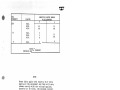
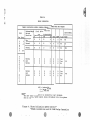
Although the 180 and 75 decoding units appear to be identical,
the components inside the case are different. To prevent a
decoding unit from being inserted in the wrong place in the
equipment box, the indexing pin and connectors are arranged
differently on two units. A test jack is provided in each
decoding unit to measure the current to the unit. The currents
tested should conform to the values given in Table B.
When the decoding current values no longer conform to the values
given in Table B, the decoding unit involved should be removed
and sent to the relay shop for test and inspection.
6071, p. 14
w11aca
~
SECTION IX
MAINTENANCE AND TESTING OF ONBOARD OVERSPEED EQUIPMENT
The axle generator, two printed circuit boards, and the
speedometer are all contained in the overspeed subsystem.
The axle generator is directly coupled to the axle of the
car or locomotive. The electrical output from the axle
generator is an AC signal with a frequency that is proportional
to speed.
One printed circuit board - the Shaper Limiter, performs its
functions as follows:
1).
Provides an AC signal to the speed governor that is
proportional to speed.
2).
Provides an output signal when the vehicle is not
moving.
3)
Produces the speedometer drive signal.
The second printed circuit board, Speed Governor,
receives the speed signal and also a DC signal from.
the Shaper Limiter printed circuit board. The DC
signal from the Shaper Limiter is passed through the
decoding relay matrix which establishes the allowable
speed limit. The circuitry on the speed governor
board compares the speed established by the signal
in the rails and the actual speed as indicated by the
signal derived from the axle generator. At any time
the actual speed exceeds that allowed by the signal
in the rails, the overspeed relay will be de-energized.
The speed governor board characteristics are modified
slightly by the wheel wear switch so that compensation may
be made in the speed signal as the diameter of the wheel
is reduced by its wear or grinding.
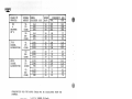
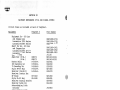
Frequency of the speed signal from the axle generator
required for the various speeds are shown in the following
table.
6071, p. 15
WABCCI
~
CLASS OF
VEHICLE
MU
&
CHOPPER
l·lU IS
3700
DIESEL
LOCOHO'i'IVES
2000
DIESEL
LOCOMOTIVES
SIGNAL
ASPECT
WHEEL
DIA1-1ETER (Hll)
SPEED
KM/H
FREQUENCY {HZ)
MAX.
MIN.
VL
(75
CODE)
914
895
876
50
50
50
205
210
214
193
198
202
VR
(NO
CODE)
914
895
876
20
20
20
89
91
93
77
79
81
VL
(75
CODE)
1050
1029
1003
35
35
35
128
130
134
118
120
123
VR
(NO
CODE)
1050
1029
1003
20
20
20
77
79
81
67
69
71
VL
(CODE)
1118
1048
980
35
35
35
120
128
137
111
118
126
VR,
(NO
CODE)
1118
1048
980
20
20
20
73
78
83
63
68
72
(75
FREQUENCIES FOR THE ABOVE TABLE MAY BE CALCULATED FROM THE
FORMULA
FREQ (HZ)
= 3. 537
X SPEED IN Kmlb:._
WHEEL DIAMETER IN METERS
The checking of the overspeed system may be done with the
locomotive stationary. An artifical speed signal may be fed
into the system by connecting an audio oscillator to terminal
posts 40 and 41 with a 0.5 Hy ohoke 20 ohms or less DC
resistance between the oscillator and the equipment box shelf
terminals.
If the choke is not used, then the OSR will not
be energized when the frequency of the oscillator is at a
frequency of 12 Hz or less. Note that the magnetic pickup
must be connected for proper operation of the system since the
inductance of the pickup is used in the circuitry of the
Shaper Limiter board. Voltage level out of the audi~
oscillator should be 0.5 volts RMS for proper operation.
6071, p. 16
WABCO
~
CODE
FREQUENCY
SERVICE LIMITS RELAY
MILLIAMPERES
A
L
LIMITS
180
MAX.
NOM.
MIN.
75
0
55
4,8
55
48
MAX.
NOM.
MIN.
2
0
55
48
MAX.
0
0
5
TABLE B
DECODING RELAY CURRENT
NOTE
These limits apply with exactly 32.0 volts
applied to· the equipment and they will vary
almost directly with the voltage applied,
therefore at 30 volts, the minimum current
at the tuned frequency may be 45 milliamperes.
Decoding relays - Style PN-59, 40 ohm slow
acting-calibration on steady DC.
Maximum Pickup
37.5 milliamperes
Minimum Release
15.0 milliamperes
On code, the pickup will be slightly less and
the release slightly higher than the steady
readings.
pc.
6071, p. 17
ti
°'
0
....J
I-'
..
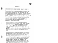
TABLE A
.
'U
RELAY OPERATION
I-'
CX)
THREE INDICATION SPEED CONTROL-FEPASA LOCOMOTIVES AND MU CARS
CODE
Seq. Freq.
u
0
w
75
p
A
R
D
Acknowledge
Final Relay Position
Switch
Decodinq
Position
Acknowledae
RP
LP
L
A
D
D
E
E
Normal
CAB SIGNAL
OSR
E
OSPR
E
Alarm
No
Name
VR
Normal
D
E
E
D
E
E
No
VL
Normal
E
E
D
D
E
E
No
VMA
Normal
Ack
Normal
D
D
D
E
E
E
D
E
E
D
E
D
E
E
E
D
D
E
Yes
Yes
No
VL
Normal
Ack
Normal
D
D
D
E
D
E
D
D
E
E
Yes
Yes
No
VR
D
D
E
E
E
D
180
D
0
w
75
N
w
A
R
D
M
0
0
E
E
v
E
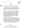
ACK= Acknowledge
D = De-energized
E = Energized
NOTE**
~~The above table is based on no locomotive (car) movement
and no artifical speed signal being introduced into the system.
Figure 4.
Three Indication Speed Control-FEPASA Locomotives and MU CARS Relay Operation
SECTION X
PARTS LIST AND ORDERING INFORMATION
If i t becomes necessary to replace components during unit
maintenance, the following procedures should be followed
in obtaining replacement parts.
a)
Standard Parts
All electrical and mechanical part replacements for
this unit can be obtained through your local Field
Office or Representative. However, many of the standard
electronic components can be obtained locally in less
time than required to order them from WABCO. Before
purchasing or ordering replacement parts, check the
parts list for the value, tolerence, rating and
description.
NOTE
When selecting replacement parts, it is
important to remember that the physical
size and shape of a component may affect
its performance in the unit, particularly
at high frequencies. All replacement parts
should be direct replacements unless it is
known that a different component will not
adversely affect system performance.
b)
Special Parts
In addition to the standard electronic components
some special components are used in this unit.
These components are manufactured or selected by
WABCO to meet specific performance requirements or
are manufactured for WABCO in accordance with our
specifications. Most of the mechanical parts used
in this unit have been manufactured by WABCO. Order
all special parts directly from your Local WABCO
Field Office or Representative.
c}
When ordering replacement parts from WABCO include the
following information:
1.
2.
3.
4.
Unit nomenclature
Unit serial number
A description of the part.
WABCO part number.
6071, p. 19
SECTION XI
EQUIPJ:.IEN'I' REFERENCES OF EL CAB SIGNAL SYSTEII
Circuit Plans are included at back of Pamphlet.
Equipment
Pamphlet#
Equipment Box - HU Cars
and Chopper Cars
Locomotives 3700 Series
Locomotives 2000 Series
Shelf for Box - NU Cars
and Chopper Cars
Locomotives 3700 Series
Locomotives 2000 Series
Fuse - 5 amp
Amplifier (60 Hz,)
S.H6072
(90 Hz.)
81-16072
Master Relay
U-5683-A
U-5684-A
180 Decoding Unit
75 Decoding Unit
U-5684-B
Style PN-59 Relay
U-5624-A
Receiver (One Unit}
U-5626-A
Receiver Junction Box
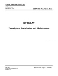
KP Relay
SH-3623
Style PL-59 Relay
SU-4549
Receiver I1ounting Bracket
Receiver Cable Grip
Acknowledging Switch
Actuator
Acknowledging Switch
Contactor Block
Tiraing Valve
Speedometer
U-5778
F-42 Converter
V=O Shaper Limiter PCB
SM6082
Speed Governor PCB
Series)
(Locomotives 3700
Speed Governor PCB (MU Cars)
Speed Governor PCB Locomotives
2000 Series
EPCO Relay
Standing Electric Cut-Out
Switch (SECO)
Change Over Switch (60/90Hz)
nagnetic Pickup, Adapter,
Cable and Connector Ass.
Magnetic Pickup (only}
Impulse Generator
OSR and OSPR Relays
Cut Out Switch
6071, p. 20
Part Number
UN451088-2701
UN451088-2702
UN451088-2703
UN451489-2901
UN451489-2902
UN451489-2903
J71165
N451463-0201
N451463-0202
N326921
N326919
N326920
N273665
N396279
Nl91500
N386991
!'1199455
N311300
J725853
J725707-0069
J337050
N451126-1701
N451033-2901
N451404-6801
N451404-7601
N451404-7602
N451404-7604
Nl43170
N300011
J725707-0068
N451125-5502
J738109
J712086
N398348
WABCCI
~
5-~-M.
REC!alVE.R
066ZO~
JUl'IC:TION
SH.
C.8262.
'.Bo><
SH.
WIRl"4Cii
IA$lJ'IM
RECIEVE/i'
R.R.
I
AS SHOWN
X3!16Z81/
~DIA.,,,,,,,
D
UN3!16Z79
5
UNZ/5777
3
x
UN.!196/!41
s
UN2JS777
3
y
L.&N.
AS SHOWN
3
3
3
x
I.e.
,'JS.SHOWA/
i!
i!
WtJ<INf
'I
UN4.JZDn
5"
UNZ/5777
UN43Z/60
5
5
UNZ/5777
UNf.J532!1
UNZl!i777
c~
ASSHOWN
2
l>w6.
514.
SeeMo.i.. To.
2
I
See h'bin To.b.
.3
2
UN311300
.DESCRIPTtOt.l
Recei"e.1'2Sf>I
'22
'Box• Junc.+ion
Connec+or.Ca.ble Grip
y• .
NOTES.·
Whit•
AS SHOWN
Pc.No.
rte RsiD
APPl.lCATION
@-4
WHIT/Ii MOUNT/Ni$ NEC/EVER ON LOl:OMOnVE
II //!1111//MUM CLEAl?ANC£ OF 3 /(z SNA££B£
MAINTAINED BETWEEN TH£ COREAND I/NY
FER/t/JUS h/ETALPA~IJF TH£ LOCOMOTIVE.
White
G.u.ul
W1.-1wo .D1~1u11•1 'x
.
8LlleK
IUD
WIR/Nti D/RliRI//Yl
fg W!011n+in9
Coi I ft:. No.
'z"
Coil Pc. No.to
F,-o,,+
Holes
WA&GQ
to ,,..,.,.
'-&/
to
l"/Jdl"
fa• Plef. Onl.:,
Pip& Tops
i
Dlo(ii,208
SH.2
MA><iMu"' length of cable 4~,
""'
. Cut to su,t inst..1lat1on ,.,.,uireMtnt
""'
Spoo.e.<":S "TO QC-
Le,r S,111.
,;z_c.c.t:.\'1CA'"S
C-«.CY\.o'\JC... . t..J,\,,..e,.c,.
Q.'C"C..
ffl.0 Ul\-\-c.d.. O"-\_oe,o ""-b-\- t'\le....
i... i
'·, (
.I .l
. ./
5-rvLL "GIM!4A Two
Figure 5.lA
Pt£cE Tll!AC:K P.E.c.e:.,vER
W•TH
j
:,_....1...__
MOU>ED Ruaae:.- Con..s
EL Cab Signal System Receiver Diagram
6071, p. 21/22
WABCD
~
n , 1 1 • ~ - - • f l l f T H C O.• f'IIN .• PA.Clft ......
VIEW'C"
PAfi'TNO.
BLESTO~~
WCTION8
ll"
tJOM.IO·
,
i~e·
,
MAX/2"
NOltl./0"
c
~-~9
-~-----~---J.1-
•
V!EW:51*
& FOR PARTNO'S ON VIEWS 'A;a"&'c" SEE OWq a,,zoB-SH.Z
PART N O . ~ ~
____.....
'
---------- CIIBLES TO---
./~
J{INCTION B{l)(
~~
J
j4fi.,..
MAX ll"
M1110·
_jl____
//
•
~~T
1
...,
MAX 12"
4zj ~ 1 0 "
__j[_
VIEW'A"
__
1"'''"1'"'"'1'"'"'1"''"'1'"'"'1"''"'1 I,1--~.~.~RT-N~U~M~BE=Rc--+----~
Ii\
I
••=~=·=.n~.O~N----1-----~M7.AT=E=R~>A~L/sn==7.c.=..=cA7.T=.o=N:---~
__
"' ___ ,__
---fflQIOffflfn--·H'ffW----·___ .__MtftCI' __ _
_ _ _ _ _ ID _ _ __
-•mClllm:llnnSl'IIJI••-•
_____
_
-----__ ___
----------
••mcartun••-to•-O*UUJD
...,. _ _ ._..,.,,nco,c;,m.,
.,,, ...
...
----TD·-·. __,
_ . , . . . . . _...,.osto,n
G.lltClOSOtoln*HN ............ UW'!'
...,.g _ _ _ _ _ _
~
_,.a.a!D ... C l - 1 ' - - ·
- - . . ~-llilQlt.HUU
Figure 5.lB EL Cab Signal System Receiver piagram
6071, p. 23/24
WABCD
~
THREE WIRE TWISTED
EQU ll'lENT BOX
•
FT-I
FT-
BK
..,
!.
..."
"'
..l!
1
"A' EHO
REVERSER
ACK.SW•
FT-2
NC
*
a:
OBU
•
BK
WG
AMPLIFIER
10
9
TWISTED PAIR
·1
FSl""".:-.!!o~-~!.l!fiii"Jl-ls!....-1-----,'FS
2P
THREE WIRE TWISTED
,N
REVERSER
'"K'END
AFS
*
"1f'END
FSSW
A
IO
HFS-1
IL
OR
••
LFS-1
3P
>NlR
OG
!>
AMPLIFIER
WO
=---t'lo,11.----
~
•
!>
&GHZ
7
J' L
B 2
932
R
CIRCUIT
BKJ:"
*
-------<11..--1•--~--::J-'+.,s::.•.,-~~
M::1.. {
\ ~ '" ,_m,
POWER SW•
0
c
c
SA 4,-0
TWISTED PAIR
L
__
.
co-,
w
3-WIRE TWISTED
TWI STEO PA IR
4R
BK
--.-
II:
...
"..
u
''e"END
II:
I•
ACK.SW.
REVERSER
~
1,---4-l!llL,
mres:
''B"END
II)
FT-I
FT-2
NC
TC
:,:
<
0:
..
3.
FT-l
FT-I
w
BK
~ OENOT£S TRAI? LINE ,JUMPER
MOTOR CAR TO r,.A• TRAILER PIN #4}
II
~)!{~MOTOR CAR TO
* SUPPLIED
·a·
BUR
DENOTES TRAIN LINE JUMPER
TRAILER (PIN#,)
BY OTHERS
IN •.. 1'1tNG WABCO TPAIN CONTROL ANO/OR CAB SIGNAL
EQUIPMENT, ALL •IRU:G EXTERNAL TO THIS EQUff'MENT
SHALL BE RUN SO THAT ISot.ATIOH IS OBTAINED FROM
OTHER LOCOMOTIVE OR CAR WIRING TO PREVENT MIS-
y
L...!!R"--f---f------;'.)CA;}-11.+*f"-tlt--{
L
L
_
-- ___ _
OPERATION OF THE TRAIN CONTROL AND/OR CAB SIGNAL
SYSTEM FROM INTERFERENCE. TRAIN CONTROL AND/OR CAB
r.-:;;;:--,I
"S"END
SPEEDOMETER INDICATOR
~:,,.9:~T•f:!~)~~~ ::
:~s!=~~s~:!!:T~A~::s
AS P0sSl9LE FROM OTHER LOCa..>TIVE OR CAR WIRIN IN
ORD£R TO OBTAIN MAXIWM ISOLATION• TWISTED ANO/OR
SHICLOEO WIRING SHALL ALSO BE USED WHERE INOICATE'.0·
~8'ENO
REVERSER
FSSW
~
HFS-1
4•
L&"C-f
~
THREE WIRE TWISTED
~~~~~A-+-+-1-'-"•-.11--~G
1
,
ALL TRAIN CONTROL AND/OR CAB SIGNAL WIRING SHOULD
BC' '"' ACCORDANCE WITH ASSOCIATION OF AMERICAN
RAILROADS, OPERATIONS ANO MAINTENANCE DEPARTMENT
"
MECHANICAL DIVISION,. MMNAL OF STANDARDS ANO
~=
.~:~~°':..~ch~:°':'o!':~L
9'2
:~~==DE~~:~'
STOCK STANDARD REVISED I 973.
5•
ALL RELAYS SHOWN WITH POWER ON AND ACKNOYILED&EMENT
MADE, WITH NO CODE BEIN& RECEIVED•
6•
ALL TWISTED WIRING TO 8£ ONE TURN PER FOOT MINIMUM•
VL
!-------:~~__,,_Rf+H"i°-.i--{Y
'--"-~~~)-<-(~~~'~G-...{
1
L.........Sos"'-~-~--"~...---'........+-:'""-III--{
.__~c=-~~~---1~
*JUNcTIONL _ _ _
I
I
I
I
I
J
BLOCK
A£Q. I 3&111-l 3
4- 0-71
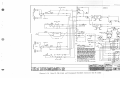
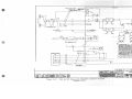
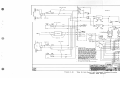
Figure 6.lA
Type EL Cab Signal and Overspeed Standard Circuits (EX MU CARS)
TYPE El CAB S IGnlll AN! ®ERSPEED
STAMJARO CIRCUITS
6071, p. 25/26
WAEICCI
~
cc
ll.' N.C. 4L
ACK SW
PA"END
I
.!!l.L.......~N-.o-.e~.(J"IJ~'<;,,~
I
I
832-A
I w,usn.£
I
I
A
I
2l
I
,-----,
EPCO
c
INSUR ING NESSURE ff•
ct.OS£ AT 120 PSI
OPEN AT 80 PSI
··a,,.
END
RBR
L ____ _JI
OSRP
OSR
l
c
TV
OSK
D
T IMINB VALVE
.. B--,.NO
34
ACK.SW.
~'9'" ENO
~N.o.~~
TO 45 LB
"IA SUPPLY
8
20
G
YBK
OBK
co
OSRP-2
OSRP-1
OSRP-1
OSRP-1
NOTES:
I.
~
"CK SW
'"B.,ENO
"·'l
~
DENOTES mA IN LINE JUIPER MOTOR
CAR TO TRAILER "A"
BUS
I
OSRP-1
IOOOMF'D
~~f--
DENOTES TRAIN LINE JUMl'£R
MOTOR CAR TO TRAILER 'B"
(PIN 1#4)
2•
BK •• 11-•'-,....,W.,_._...._.......,,_
l•
I
* SUPPLIED BY dTH£RS
::t~~1Ru:L~o"::!~.:~!~~~ ~~ :::.=·=T
IN WIRING WABCO TftAIN CONTROL AND/DR CAB SIGNAL
OTHER LOCOMOTIVE Oft CAR WIRING TO PREVENT MISOl'ERATIOH OF Tli£ TR> IN CONTROL ANO(OR CAB SIQNAL
SYSTEM FROM INTERFERENCE. TRAIN cOtfTRot. ANO/OR CAB
SIGNAL WIRf:S SHALL BE RUN THROUGH )'HE:IR O'IN FERROUS
CONOUIT (PIPE) AND BE PIIY<"ICALLY SEPARATED AS ""CH
AS POSSIBLE FROM t\T!.ft='q t.OCOt'OTIVE OR CAR WIRINe IN
ORDER TO 09TAlt• 1/.AXIWM ISOLATION• TWISTCD ANO/Oflf
SHll:L0£0 WlftlNa SHALL ALSO DE US£0 WHERE' INDICATED·
I
IL _______
I
q
Yj'
OftTIO,.,.L
RECORDER
USE
4•
ALL TRAIN CONTROL ANG/OR CAD SIGNAL li'UUNG SHOULD
BE IN ACCORDANCE WITH ASSOCIATION OF AMERICAN
ftAILROAos,
OPERATIONS AND MillNTEHANCE O£PARTM£NT.
MECHANICAL DIVISION, WtNUAL Of' STANOARO!I AHO
lffl'.COINEM>EO PltACT ICU• Sl:CT ION F LOCOMDT IVES ANO
:~:~R~~:.c!:.:1~:io•:~~~
$.
PRACTICE FOR ROLLINS
ALL RELAYS 8H01IN WITH POWER ON AND ACIOIOYLE:D8EIIE:NT
aoe:.
WITH NO CODE BEIMI RECEIVED·
. - - - - - - - - - . . - - - - - - - - - - - - - - - - -......-
TYFE EL CAB SIGNAL AIIJ OYERSPEED
STAM>ARD CIRCUITS
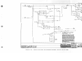
Figure 6.lB
Type EL Cab Signal and Overspeed Standard Circuits (EX MU CARS)
6071, p. 27/28
WABCD
~
r--1
TWISTED SHIELDED
PAIR BELDEN 1401 OR
EQUIVALENT
I
-- --
EQUll't.£M' BOX
- - - - --- --- --- --- - - - --- --- - - ,
I
'
I
I
,....
I
I
15
......
MM
HS
•
3
•
•
2
I
II
SPEED
...
SPARE
WO
SPARE
0
"A' END
r------,
OG
OOVERHOR
NO,l 40•7802
OBU
I
I
I
I
ov~'--~...-,1-+1-i:Fl:1-'"-"'--'-~~~-<1
OY
••~~~-t-+<1-t--cFu-~~~~1--~-u
G
SPEEDOMETER-
L
~~A!!!!!_
I
t...l
0
ys
BLOCK
1
I
I
L
11
8 END
USE
o
••
I
6
'
:~~~~;~
I
*JUNCTION
...J
c
E}
OR
3 t
I
I
II
BUS
::.
L
TO METER-~-.....- t - + - t - U - U - ~ ~ - - - - - - u ~ - -weu
-~~---~
I
I
co
I
I
I
I
I
I
I
_ _ _ _ _ _ _ _J
NO'IES'.
I•
•
C~R·,~1=.:~,
LINE
JUWER
MOTOR
~ ) i { ~ Q E N O T E S TRAIN LINE JUMPER
MDTDII CAR TO TRAILER •a• (~IN #4)
*
.JUNCTION
2.
* SUPPLIED
3.
IN WIRING WABCO TRAIN CONTROL ANO/OR CAB SIGNAL
BLOCK
BY OTHERS
::l~:T1'\J:L~Ow::;e.:~:;r~ i~ ~:i:.:~l=T
OTHER LOCOMOTIVE: OR CAR WIRING TO PREVENT MISOP£RATION OF THE TRAIN CONTROL AND/OR CAB SIGNAL
SYSTEM FROM INTERFERENCE• TRAIN CONTROL ANO/OR CAB
:«::~r•t=~~,~~ : =,:~s~::,::\:E:;:s
AS POSSIBLE FROM OTHER LOCOMOTIVE OR CAR WIRING IN
ORDER TO OBTAIN MAXIMUM ISOLATION• TWISTED AND/OR
SHIELDEO WIRING SHALL ALSO BE USED -.£RE INOICATEO.
4•
ALL TRAIN CONTROL AND/OR CAB SIGNAL WIRING SHOULD
BE IN ACCORDANCE WITH ASSOCIATION o,r AMERICAN
RAILROADS, OPERATIONS AND MAINTENANCE DEPARTMENT,
MECHANICAL DIVISION, MAMJAL OF STANDARDS AND
RECOf61ENOED PRACTICES, SECTION F, LOCOMOTIVES ANO
ELECTRICAL EQUIPIAIENT, WIRING PRACTICE FOR ROLLING
STOCK STANDARD REV I SEO 1973.
5.
ALL RELAYS SHOWN WITH POWER OH AND ACKN09.l!:08EMENT
M\DE• WITH ND CODE BEINB RECEIVED•
TYPE EL CAB SIGNAL AND OVER SPEED
STANDARD CIRCUITS
..........
-Q
11775
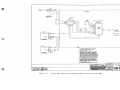
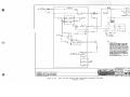
Figure 6.lc
Type EL Cab Signal and Overspeed Standard Circuits (EX MU CARS)
6071, p. 29/30
WA8CCJ
~
r---------------;;;-BO;------------,
(BELDEN 19207 OR EqUIVALENT)
y u
TffaSE TWO CA8LES
THREE WIRJ; TWISTED
}
TWO WI RE TWI STEO
~ST .,E IN A
.0111
SEPARATE CONDUIT
IZOK
,.
BELDEN 19101 OR EQUIVALENT
R8U
F
'IOlfZ
150K
W8R
15
BK
.
.
a:
IN IR
ACK.SW.
REVERSER
~
FS
IP
BR
FT
FT-
NC
10
AMPLIFIER
OOHZ
0
ii!
OK
..,..,___r~cc+~~~~-'-"~~-<!--~~~~~~--''--+-~~~~~--'"-~~~~~~~~~~~~-'0;1--~~•~o<--~~~~~~~rw:m.~-1-~~~Ro \E;'"""
"
~
'"I
FS-1
FS
0
IS
MR
FS
IP
••
I
TWISTED PAIR
(BELOEN I 92 02 OR EQUIVALENT)
en
OR
I
C ---~~~~-=c_._~~~--··.I
FSSW
IA
JA
.··o
;·L
HFS-1
-:-:::
18
LFS-1
10
1
~
I
+.
*
DA~;~RY{ ~
-64
a
&OHZ
..
9
CIRCUIT
Bl<R
AMPLIFIER
II
~
OG
~
WO
""
']
3P
'"]
RO
b
RR
5A 4AG
Fl
F42 CONVERTER
"{~ AJT
SA 4AQ
"~"'
BK
B
TWISTEO PAIR
{BELOEN 19102 OR EQUIVALENT)
c
NOTES:
I•
2.
EPCO
c
BK
zoow
~~=~~~
R K
19
SECO
R
co-1
RBK
A
3.
WBK
I
R
::
TW(~7:E ,~~~ :: =~sr~:~~Hs~=::.:T~~A:E=~S
AS POSSIBLE f'ROM OTHE:R LOCOMOTIVE OR CAR WIRING IN
ORDER TO OBTAIN MAXIMUM ISOLATION. TWISTED AND/OR
SHIELDED WIRING SHALL ALSO BE USED WHERE INDICATED.
18
ZRSECO
~~~:.~=~·=T
IN WIRING WA8CO TRAIN CONTROL ANO/OR CAB SIGNAL
OTHER LOCOMOTIVE OR CAR WIRING TO PREVENT Ml SOPERATION OF THE TRAIN CONTROL AND/OR CAB SIGNAL
SYSTEM FROM INTERF'ERENCE. TRAIN CONTROL ANO/OR CAD
19
3R
* SUPPL I EO BY OTHERS
~:~~=TAu:L~o·~:~.~~~~~~
RY
0
24
BUR
ALL TRAIN CONTROL ANO/OR CAB SIGNI\L, WIRING SHOULD
BE IN ACCORDANCE WITH ASSOCIATION OF AMERICAN
RAILROADS, OPERATIONS ANO tMINTENANCE DEPARTMENT
MECHANICAL DIVISION MANUAL OF STANDARDS ANO
'
RECOtMEND£0 PRACTlcis, SECTION F I LOCOMOTIVES ANO
ELECTRICAL EQUIPMENT WIRING PRACTICE FOR ROLLING
STOCK STANDARD REv1SE:o 1973.
4.
ALL RELAYS SHOWN WITH POWER mt AND
MADE• WITH NO CODE BEING RECEIVED•
5.
ALL TWISTED WIRINB TO BE ONE TURN PER FOOT MINIMUM
ACKNO'M.EDOEMENT
R
RG
*'
L ___________
JUNCTJON BLOCK
M-------------·~
WLTICONOUCTOR
CADLE-INCLUDE 3
WIRES SHOWN ON SH 3606
TYPE EL CAB SIGNAL ANO OVERSPEED
STAMlARO Cl RCUITS
1-!!#l~~(&I-~:11775
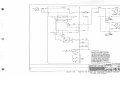
Figure 6.2A
Type EL Cab Signal and Overspeed Standard Circuits
(Chopper Cars)
D 451276
.ax
IMU.-OtlU. . . .
6071, p. 31/32
WABCD
~
,--------
ACK SW
1ll-..:;j--N.O.
II
TU.. NI VA\.VE
EQUIPI.ENT BOX - - - - - - - - - - - - - ,
I
.°'\
BH-A
•
TV-I
I
r-----,
£PCO
RBR
L ____ _JI
OPEN AT
---PSI~
,-.--cl
TV
I
cL
~
IL__ _ ·_···JI
I
c
I
~:
•
I
i
I
20
10
CLOSE ~T---PSI
t OPEN
K
I
I
AT - - -PSI
SUPPRESS JON
PRESSUI£ SWITCH
YBK
ACK SW
co
'-OTES:
R
l2
L ____ _JI
I•
N.C.
2.
0
30
....i
30
8US
IOOOMFD
c "' •• 11-•=--,-wv--""'"-."""'"'
..
9Y OTHERS
IN WIRING WABCO TRAIN CONTROL AND/OR CAB SfGNAL
EQUIPM!E:NT • ALL WIRING EXTERNAL TO THIS EQUIPt«NT
SHALL BE RUN SO THAT ISOLATION IS OBTAINED rftOM
OTHER LOCOMOTIVE OR CAR WIRING TO PREVENT MISOPERATION OF THE TRAIN CONTROL ANO/OR CA9 SIGNAL
SYSTEM FROM INTERFERENCE. TRA J N CONTROL AND/OR CAB
SIGNAL WIRES SHALL BE RUN THROUGH THEIR OWN FERROUS
CONDUIT (PtPE) ANO BE PHYSICALLY SEPARATED AS MUCH
AS POSSIBLE FROM OTHER LOCOMOTIVE' OR CAR WIRING IN
ORDER 'l'O OBTAIN ..."AXIMJM t!OLATION. TWISTED AND/OR
SHIELDtD WIRING SHALL ALSO 9£ USED IWHERE INDICATED·
0:
0
0
* SUPPl I £0
3.
ALL TRf.lN CONTROL ANO/OR CAI SIGNAL WIRING SHOULD
BE tN ACCORDANCE WITH ASSOCIATION OF AMERICAN
RAJLR~os. OPERATIONS ANO MAINTENANCE DEPARTJ.eNT
M£CHANJCAL DIVISION• MANUAL OF STANDARDS ANO
•
Rl!CQt&CNOl!:D PRACTICES SECT JOH F LOCOMOT I V£S ANO
ELECTR.CAL EQUIPMENT ·wrRING PRACTICE FOR ROLLING
STOCK f;TANDARO RE'Vlsio 1973.
4•
ALL Rd.AYS SHOWN Wint POtl£R ON AND ACKN>lt.EOGEMENT
Ml\0£ w:nH ND CODE BEING RECEtYf!D·
OSRP
.
OPTIONAL
RECORDER
USE
I
Q ~
L.._ _ _ _ _ _ _ _ _ _ _ _ _ _
_J
TYPE EL CAB SIGNAL AN> OIIERSl'EED
STN«lAAD CIRCUITS
--- 0 451276
11n1
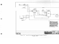
Figure 6. 2B
Type EL Cab Signal and Overspeed Standard Circuits
( Chopper Cars)
.......... ...,.....
~
~ l60s
6071, p. 33/34
WRBCD
~
JUNCTION
-------;71
SHIEL0£0-TWISTED
PAIR
BE:.DZN ,4.l8 OR EQUIVALENT
I
I
I
I
I
I
I
I
I
I
L_ ___/ ••
ll&V
II
M'.lTES:
I•
2.
* SUPPLIED BY OTH£RS
IN WIRING
:::l~T
WABCO TRAIN CONTROL AHO/OR CA9 SIGNAL
Au:L~ow~~G .:~:;~:;
J~ :::.:~':-'
OTHEfl LOCOMOTIVE OR CAR WIRING TO PM:Vl!:NT MISOPERATION OF THE TRAIN CONTROL ANO/OR CAB SIGNAL
svsn:u FROM INTERF'!'.R£NCE.TftAIN CONTROL AND/OR CA8
SIGNAL WIMS SHALL SE RUN THROUGH THEIR OWN F'!'.RROUS
CONIJUJT (PIPE) AND Bl!'. PHYSICALLY SEPARATH AS WCH
AS POilsu,u: FRON ~ R LOCOMOTIVE OR CAR WIRING IN
ORDER TO 08TAIN MAXIMUM ISOI..ATION. TWIS'R:D ANO/OR
SHll!:LO£D WIRIN8 SHALL At.SO Bl! USED ~Re: INOICAT!:O.
3•
ALL TRAIN CONTROL ANO/OR CAB SIGNAL WIRING SHOULD
BE IN ACCORDANCE' WITH ASSOCIATION OV AMtRICAN
::~:::!£ ~~r:..OIIS
~=A~;r:~=.::•:.,TMDtT,
Rl!:CotM:NH'.O PRACTlciS SECTION F LOCOUOTIWS AHO
ELECTRICAL EQUIPMENT• ·w,n1Na PRACTICI!: FOR Rot.I.ING
STOCK STANDARD REVISED I 973.
4.,
ALL RB.AYS SHOJIN WITH POWER ON ANO ACKNO'M..EDGEMENT
MA.OE, WITH NO CODE BEINO RECEIWD•
TYPE EL CAB SIGNAL AND OVER SPEED
S{AMJARD CIRCUITS
--- D 451276
11771
Figure 6. 2C
Type EL Cab Signal and Overspeed Standard Circuits
( Chopper Cars)
-
......... ...._
6071, p. 35/36
WAS CD
~
EQU IPl.ENT BOX
YB
THREE WIRE TWJST£0
•
A
FT-t
SK
.
......"
.,
"A''ENO
REVERSER
!I
ACK .SW•
FT-I
*
NC
"'
,_~
WG
w
BK
BK
TWISTED PAIR
FS
0
>P
THREE WIRE TWISTED
"1."END
REVERSER
... ,.., END
f'SSW
AFS
*
IA
90
HFS-1
IL
OR
OG
AMPLIF'IER
10
LFS-1
'"1
MR
s
FS
WG
-]
3P
WO
B i
832
CIRCUIT
BKR
*
+32
..~.. {-------40..---11'---,\c---:J-:-':"-:-<~~--I F42 CONVERTER
-32
~
-:n
WBK
c
F2
TWISTED PAIR
•L
-
-
r-:::
I
JI
2 --EPc0....._,c~o'----rll---=-----.
1
'i
I
------<1
CO-I
w
3-WIR[ TWJSTEO
TWISTED PAIR
4R
1
•e"END
REVERSER
ACK.SW.
FT-2
NC
- ~ ~ - - - - - · - FT- I
''e"END
NOTES:
re
"..."'
I•
<
a:
2.
P'T-1
w
BK
3-WIRE TWI STEO
.. a"ENO
REVERSER
-*-
'e•
1
BUR
* SUP Pl I Et'
SY OTHERS
I
IL
IN •. ,-IJJG WASC'.1 TPAIN CONTROL ANO/OR CAB SIGNAL
EQUIPUENT. 'LL ...
EXTERNAL TO THIS EQUIPJ.ENT
SHALL BE RUN SO THAT ISOLATION IS OBTAINED FROM
OTHER LOCOMOTIVE OR CAR WIRING TO PREVENT MISOPERATION OF THE TRAIN CONTROL ANO/OR CAB SIGNAL
SYSTEM FROM INTERFERENCE• TRAIN CONTROL AND/OR CAB
,~wa
~:,::~ r·~=~~
y
_
R
-- _
-
-
-
,~;~ =~ =~~s:~:~:Hs:~!!:r::"A:E:;:s
AS POS~l':1L£ f'qOM OTHER LOCOMOTIVE OR CAR WIRING IN
ORDER TO OBTAIN '4AXIMUJ.1 ISOLATION• TWISTED AND/OR
SHl:'.L1:1r::o WMING SHALL ALSO B£ USED WHERE INDICATED.
END
FSSW
BFS
R8K
II
I~
BK
"a:
!!!
...
...a:"
..
~-1---"--"
HFS-1
3•
ALL TRAIN CONTROL AHO/OA CAB SIGNAL WIRING SHOULD
BE IN ACCORDANCE WITH ASSOCIATION OF AMERICAN
RAILROADS, OPERATIONS AND MAINTE~NCE DEPARTMENT,
Me:CHANICAL DIVISION, ~MIAL OF STANDARDS AND
RECOY«NOED PRACTICES, SECTION F, LOCOMOTIVES AND
ELECTRICAL EQUIPMENT, WIRING PRACTICE FOR ROLLING
STOCK STANDARD REVISED 1973.
4•
ALL RELAYS SHOWN'WITH POWER ON .ANO ACKNOYC.EOGEMENT
IM\OE WITH NO CODE BEING RECEIVED·
5.
ALL TWISTED WIRING TO BE '"'ONE"" TUftff PER FOOT MINIWM·
LFS-1
932
DIESEL LOCOl.l)TfVES f37oo)
flrd. 13SS2G-.S?
107
,-zz-74
Figure 6.3A
TYPE El CAB SIGNAL ANJ 0/ERSPEEO
. STANlARO CIRCUITS
Type EL Cab Signal and Overspeed Standard Circuits
(Diesel 3700)
6071, p. 37/38
WABCC
~
,--------ti
EQUIPl.£NT BOX - - - - - - - - - - - - ,
•
•
TIIIINI VALVE
1
I
OSRH
'A"'ENO
.... \ ......r~v~-~·~~~~~~~~~~~~--,
I
~~~~~~~
EftCO
~
TV. t
II
.-----,
EPCO
RllR
L ____ _JI
TV
•
20
G
11
OBK
!\OTES:
co
OSRP-3
J•
2•
OSRP-2
ll
N•C•
J.,
eus
OSRP
IOOOWO
115 ••
I
+
ALL TRAIN CONTROL ANO/OR CAS SIGNAL WIRING SHOULD
BE IN ACCORDANCE WITH ASSOCIATION OF AMERICAN
RAILflPADS, OPERATIONS AND MAINTENANCE DEPARTM!NT •
MECHANICAL OIVISION• MANUAL OF STANDARDS ANO
::~:~DE::~~~s .•~:~~otfPR:~h~~o:g! ·~L~:
2t
c
IN WIRING WABCO TRAIN CONTROL AND/Off CA9 SIGNAL
EQUJFiMtNT, ALL WIRING EXTERNAL TO THIS EQUlflM!NT
SHALL BE RUN SO THAT ISOLATION IS 08TAIH!'D Ffff>M
OTHEflt LOCOMOTIVE Oft CAR WOtlNG TO PREVENT MISOPER~TION OF THE TRAIN CONTROL AND/OR CA9 SIGNAL
SYSTEM FROM INTERFERENCE.TRAIN CONTROL AND/OR CAB
SIGNAL WIRES SHALL BE RUN THROUGH THEIR 011N FERROUS
CONDUIT (PJPE) ANO BE PHYSICALLY SEPARATED AS WCH
AS POSSIBLE FROM OTH£R LOCOMOTIVE: OR CAR WIRING IN
OAKR TO 09TAIN MAXlhl.fM l!OLATION. TWISTED AND/OR
SHIELO!:D WIA If.IQ SHALL ALSO BE USED WHERE INDICATED.
AC\?W
OSRP-f
••
* SUPPL l!'.O BY OTHERS
TAD
STOC~ STANDARD REVISiD 197J.
I
4•
ALL R.ELA VS SHOWN WI TH POWER ON AM> ACKNOR.EDGEW:NT
M\DE WITH NO CODE BEING RECEIVED•
..
OPT ION.'L
RECOROEA
USE
I
•
Q ~
'-------------_J
DIE"1!L LDCOMlTlvt:S (3700)
TYl'E EL CAB SIGNAL AM> <MRSl'EED
STNIWID CIRCUITS
Figure 6. 3B
Type EL Cab Signal and Overspeed Standard Circuits
(Diesel 3700)
6071, p. 39/40
wA,acc
~
--
...,
~
I
I
I
SH I EL OED TWISTED
PAIR BELDEN uoa
OR EQUIVALENT
I
I
I
I
I
I
40
I
L_ __,.
a
1003141J
3
10491&1
811W
ll&V
e
z
1021MM
I
e
II
Sl'EEO
eOVEANOR
N<l5140.t-
7601
Sl'AII£
co
IIO
au
PAR£
r-----,
I
I
I
I
I
TO METER
oe
----1---'5!.....--l+Jl--l!!sP:.!ML-_~:::>----....l!!!:l<.-----'
L
3f
ov----+---'-----11-+l--"C!..::..-'---.1~
,<
•t.r:'E·J:::..
r----__
-_-__ I
I
I
I
I
ci
D
I SPl£DmiE~n:==•~---l---.!!R_ _-I-.+-"""-+----,()
L!!~~~~.J
I
O
..
I
I
•
L _______ _ --- --- --- --- ------ --- ---
I
'
--- --- --- --- ---
J
t«ms:
I •
*
2.
IN WIA'._ING
SUP~ 11:D BY OTH1!:RS
~=~:.=·=
WABCO TRAIN CONTROL ANO/OR CA9 SIGNAL
i!:l~~L~o·::::~.:~~;::.1~
TO METER
OTJEft LOCOMOTIVE' OR CAR WIRING TO PREVENT Ml90P!RATION OF THE TRAIN CONTROi.. AHO/OR CAB SIGNAL
SYSTl!l.1 FROM INU:R,.l!RENC«. TRAIN CONTROL ANO/OR CA9
SIGNAL WIMS SHALL DI!' RUN THROUGH TH£1R OWN RmtOUS
CONDUJT (Pll'f!) AND Bit PHYSICALLY SltPA..ATl!D AS ..,CH
ov-~~''---~--'-~-1-<>-1-->c'--+-'
AS PQPtl!ILI: FROM OTHER LOCOMOTIVE OR CAR WIRING IN
ORDER :1°0 09TAIN IMXIIIJM ISCN.ATION. TWISTED AHO/Off
SHll!l.Cl!ED WIRING SHAt.L ALSO 91! US£0 IW«RI: INDICAT!'D.
~~'~---"------H'"1---'
SPEEDOMETER
ys
OY
.,..,_l_ _..2..__-j~f"S,:,PM-"--'-'I
I
c
OPT•O..A~
RECORDER
USE
oeu
I
I
I
:R
G}
OR
I
L .!_A!_J~C~D!,__J
:S.
ALL T~IN CONTROL ANO/OR CAB SIGNAL WIRINa SHOULD
8£ IN~CCORDANCE WITH ASSOCIATION CW AM!'RICAN
=~Mt:.: :::::!!:"'
~=Ar:r:~:.::"::On.NT •
Rl!CMN!MttD f'RACTlcis. SECTION ,. LOCOMOTIVES ANO
~u:cT~ICAL t:QUIPM!'NT ......... PRACTICE FOR ROI.LING
STOCK STANDARD REVISED lt?J.
4.
ALL R£l.AYS SHOWN Wl1H POWER ON AND ACKN:>111.EDGEMENT
M\OE ~Int NO CODE BEING RECEIVED•
/
DIESEL LOCO...,TIVES (3700)
TYPE EL CAB SIGNAL ANO OVER SPEED
srAMJARD CIRCUITS
Figure 6.3C
Type EL Cab Signal and Overspeed Standard Circuits
(Diesel 3700)
6071, p. 41/42
WABCD
~
THREE WIRE TWISTED
w
FT-J
f'llJll'IAFt.lT MX
BK
,.A, 1 ENO
REVERSER
ACK .SW•
P'T-1
*
FT-2
NC
...
OBU
•
BK
AMPLIFIER
to
BK
TWISTED PAIR
'",r-P_,,o___.,"'is MR ~2"'•'-t----,::
...
THREE WIRE TWISTED
'1
JN JR
11
"A ENO
REVERSER
.t,:• END
AFS
*
FSSW
A
90
IL
HFS-1
OR
OG
••
l.FS-1
AMPLIFIER
WO
CIRCUIT
BKR
*
\_:J~::~,~c-1
ul:~ { _ _ _ _..._ _
~
w
..
..
"'
."..
TWISTED PAIR
3-WIRE TWISTED
TWISTED PA IR
18
1.--------..,,..
BK
''B"END
--.-
0:
!fl
(,)
0
n2 CONV£RT£R
''o.,ENO
0:
ACK.SW.
FT-I
FT-2
NC
NOTES:
,. *
TC
(,)
<
.-T-1
FT-I
2•
w
THREE WI RE TW I STEC
BK
"e•ENO
-.-
REVERSER
"
11
8'ENO
FSSW
BFS
••
IL
HFS-1
3.
LFS-1
8
B-32
832
SUPPL I EC 9Y OTHERS
I
IL
IN WIRING WABCC, TPAIN CONTROL ANO/OR CAB SIGNAL
EQUIPMENT, l,LL *l-11:;G EXTERNAL TO THIS EQUIPMENT
SHALL BE RUN SO THAT ISOLATION IS OBTAINED FROM
OTHER LOCOMOTIVE OR CAR WIRING TO PREVENT MISOPERATION OF THE TRAIN CONTROL ANO/OR CAB SIGNAL
SYSTEM FROM INTERFERENCE• TRAIN CONTROL ANO/OR CAB
SIGNAL WIRES SHALL BE JIUN THROUGH THEIR OWN FERROUS
CONDUIT (PIPE) ANO BE PHYSICALLY S!:PARATED AS MUCH
AS POSSl9LE FROM OTHER LOCOW>TIVE OR Cli,R WIRING IN
ORDER TO OBTAlff MAXIMUM ISOLATION· TWISTED ANO/OR
SHl::u~c:o Wl.flNG SHALL ALSO BE USED WHERE INDICATED.
_
ALL TRAIN CONTROl AND/OR CA9 SIGNAL WIRING SHOULD
8£ IN ACCORDANCE WITH ASSOCIATION OF AMtlUCAN
RAILROADS, OPERATIONS AND IMINTENANCE D£PARTMENT,
M!:CHANICAL DIVISION, MAMJAL OF' STANDARDS ANO
RECOIM:HOED PRACTICES, SECTION F, LOCOMOTIVES AND
ELECTRICAL EQUIPMENT, WIRING PRACTICE FOR ROLLING
STOCK STANDARD RE:VISED 1973.
4 •
ALL RELAYS ARE SHOWN WITH POWfR ON AND ACKNOWLFDGEMFNT
MADE• WI TH NO CODE BE J NG RFCE I VEO
S.
ALL TWISTED WIRING TO Bf ONE TURN PER FOOT MINIMUM
-- -
-
-
"e"ENO
SPEEIKNETER INDICATOR
L-------"-+e-1-,'r.;-~-:-.:: -,
++t-i"'I---M--<.,L
'-------"-R
I
'------""-+4+'-"--,111-{
II
I
I
OIFSFL LOCOMOT IVF{2oso)
Jl£Q. I 3GtZl-1
G.O.
01
07•- 0-1•
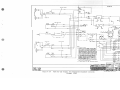
Figure 6.4A
TYPE El CAB SIGNAL AMJ OYERSPEED
STAr«JARO CIRO.JITS
Type EL Cab Signal and Overspeed Standard Circuits
(Diesel 2000 seri.s)
I
II
6071, p. 43/44
WABCD
~
a::.
• tUJIG VALV!"
H.1'flo.: ·' •l
I
.,.~ffC
u,-1
[PCO
!531
--;r,
1.,
TVC
Cl
L ____ _JI
TV-3
OSfiP
TV
"
1' tMIHli VALV(
"'B""f"HO
¥ft11STL£
0
TO 45 LB
,.IP SUP,.LY
....
G
111
"
20
10
~----T_vc___--,. I
"'"
~----~TVC=--~·-------------'
CLOSf AT 6.;:,NG
f fl.:tssunr
120 PSI
SWITCH
OPFN AT
10 PSI
..,. ..
ACK SW
Y"3K
CO
Y&K
'------'-=--'
.•
VOA
17
I
,,
I
L ____ _J
,,
N.C.
~--=o,.s:.:.••c.-;;.:•~-----"
O RP-
.•.
ACK SYi
I
I
I
lO·..___.,:O,oS;;.R•:__ _ _
NC_~
BU!
I
OSRP
NOTES:
IOOOMFO
I •
•• •• I f-+"-,e--wv--+--""---<t-,-,
2.
I
I
I
IL ________ ·
* SUPPL 1£0
!5Y dTHERS
U1 WIA ING 'IIIA9C'O TR~ IN COHTROL ANO/OR CA9 SIGNAL
EQUIPMENT• All JlflAING [:,tT£ANAL TO THIS EOUIPWNT
SHALL 8£ AUN SO TH#T ISOLATION 1- OBT• INf'I' FPOU
OTH£R LOCOMOl tvE OP CAR WIRING TO PR[',/£NT MISOPERATION Of' TM[ TRI IN CONTl'lot ANO/OR CAB Sl6HAL
SYST£M F'ROU INT£RF[R£NCE .. TR, 1N CONTROL ANO/OR CAB
SIGk,\L WIRES SHALL !,£ RUN THROUGH THEIR OWN F£ .. ROUS
CONDUIT (PIPE) ,No BE PIIY"'ICALLY StPAR.-TCD AS ....CH
AS POSSIBLC F"ROM nTLflt"III LOCCl'..,TIVE" OR CAA WIRING fN
ORDER TO OBTAH :.:AXhaJ'-' ljOL:.TION,1 TWl~TCD AHO/Off
SHl£LDED WIRING SHALL ALSO 8£ USCO Jl'HER£ INDICATCO.
I
OPT IOf.,j#,L
RECORO(R
:,.
usr
ALL TRAIN CONTROL ANO/Oft CA! SIGNAL WIRING SHOULD
BE IN ACCORDANCE WITH ASSOCIATION OF AMCRl~AN
R,t,ILROADS,
OPt:r:tATIONS ANO •tfrlT[NANCE D(PARTMENT.,
MCCHANICAL DIVISION, MANUAL OF STANDARD"' ANO
:~;~~:oc:::;:.;:s ·.!!~~!O:R:C1 ~~~ ~L~=
1
Q ~
_J
STOCK STANDARD R[Vlsi:o I 173.
4 •
ALL Rf LAYS ARE" SHOWN WJTH POWFR Otf ANO ACKN0"1.£06£Mf"NT
MA.Of. WITH NO coor Bf ING R£CflV£0
,---------.--0-,,-s-,-L-l_OC_OYO_T_I_VF_s"'"(,-.-.-o"'"l-------,-+
TYf£ EL CAB SIGNAL ~ OVERSl'EED
STAl\llARll CIRCUITS
Figure 6.4B
Type El Cab Signal and Overspeed Standard Circuits
(Diesel 2000 seriies)
6071, p. 45/46
WABCD
~
SHIELDED -TWISTED
PAIR BE"LOEN 8408
OR EQUIVALENT
/:
I
I
I
I
,.
I
I
I
I
I
L---J
,--
-- -- -- -- -- --
I
I
I
I
I
••
I
I
/ ••
I.,
15
WR
BKW
I 8&V
I 080MM •
______
....
ro
.....
I 099MM
I
II
SPEED
GOVERNOR
N4514047"0<>
SPARE
WO
SPARE
OG
I
I
I
0
ov--'-------,,--l....+---~S~PM~-~''-------{)
ca
eus
:R
I
c
E}
u
I
L ~~A!.2!!._ .J
O
I
I
OY
*JUNCTION
BLOCK
!~~:
5
g~E s~ 3 607)
USE
,.
rs
832
SPEEOOMl TER-
I
g:~~~~:~
OBU
•
I
I
e
I
METE•--=----11-4....~--...::S~P~,.!..------Q-----'"""'u"-----'
I
II
I
I
3
I I I 8JAIA.
2
I
I
r-----.
- - - - --- --- - - - - --- --- --- - - - ,
1
I
I
I
EQUIP!,£NT BOX
6
IL _____________________ ~
J
r-----,
I
ro
I
II
I
I
c
I
32
ov-~--t--t-t>+-~-----~
I
I
SPM-1
5
W:TER--''---_,__-H>+-"-------'
u~~'!!L J
SPEEDOMETER-
!\OTES:
,. *
* JUNCTION
BLOCK
2.
SUPPLIED SY OTHERS
IN WIRING WASCO TR.. l'\4 CONTROL ANO/OR CAB SIGNAL
EQUIP"4ENT ALL WJRING EXTERNAL TO THIS EQUIPMENT
SHALL SE ~N SO THAT ISOLATION IS OBTAINED FROM
(SAME ONE AS
SHOWN ON SH 3607)
OTHER LOCOMOTIVE OR CAA WIRING TO PREVENT MIS-
OPERAT ION OF TH£ TRAIN CONTROL AND/OR CAB SIGNAL
SYSTEM FROM INTERFERENCE• TRAIN CONTROL AND/OR CAB
..
~::~Twi:~;E)~~~ : : :~sr~=~:Hs~::T:"A:E:::s
AS POSSl9LE FROM OTHER LOCOMOTIVE OR CAR WIRING IN
ORDER TO OBTAIN MAXlt..UM ISOLATION. TWISTED AND/OR
SHIELDED WIA ING SHALL ALSO BE USED WHERE INOICATEO.
3.
4.
ALL TRAIN CONTROL AND/OR CA9 SIGNAL WIRING SHOULD
9E IN ACCORDANCE WITH ASSOCIATION 0, AMERICAN
RAILROADS, OPER,t,TIONS AND MAINTENANCE DEPARTMENT,
f'-"CrtANICAL DIVISION, MANUAL OF STANDARDS ANO
RECOMMENDED PRACTICES_, SECTION F, LOCOMOTIVES ANO
ELECTRICAL EQUIPMENT, WIRING PRACTICE FOR ROLLING
STOCK STANDARD REVISED 1 973.
ALL RELAYS ARE SHOWN WITH POWER ON AND ACKNOWLEDGEMENT
MADE WITH NO CODE BEING RECEtVED
OIFSE'l LOCOUOTIVf'~
(2050)
TYPE El CAB SIGNAL AND OVERSPEEO
SfANOARO CIRCUITS
WAEICD
Figure 6.4C
WESIIICIIIIUS( •
. u t C8IIPMY
Type El Cab Signal and Overspeed S~andard Circuits
(Diesel 2000 series)
6071, p. 47/48