1
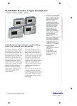
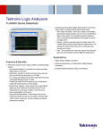
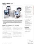
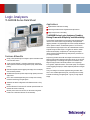
Logic Analyzers
TLA5000B Series Data Sheet
Applications
Digital hardware verification and debug
Monitoring and measurement of digital hardware performance
Single microprocessor or bus debug
TLA5000B Series Logic Analyzers Combine
Debug Power with Simplicity and Affordability
Features & Benefits
500 ps (2 GHz)/32 Mb timing record length to capture intermittent events
over a wide time window
125 ps resolution MagniVu™ acquisition simultaneous with timing or
state acquisition to find elusive timing problems quickly, without double
probing
Glitch and setup/hold violation triggering and display to find and display
elusive hardware problems
235 MHz state acquisition provides analysis of high-speed synchronous
digital circuits
iView™ time-correlated digital-analog view to clearly see how analog
anomalies are affecting your digital signals
34/68/102/136 channel configurations offer flexible solutions to fit any
budget
Microsoft Windows XP Professional PC controller provides familiar user
interface with network connectivity
Remotely control and monitor the TLA over the network using either
hosted mode or the built-in Windows XP remote desktop
The affordable TLA5000B Series logic analyzers make high-speed timing
resolution, fast state acquisition, long record length, and sophisticated
triggering available to any digital designer who needs to identify initialization
failures, operation crashes, and intermittent operation. For first-time as
well as experienced logic analyzer users, the TLA5000B Series is ideal for
single-bus timing and state analysis. An intuitive user interface, familiar
Windows-based desktop, and OpenChoice® networking and analysis
features make the TLA5000B Series logic analyzers easy to network into
your design environment.
500 ps timing resolution and 32 Mb record length with simultaneous 125 ps
MagniVu timing resolution within each acquisition means you can measure
digital signal timing on increasingly faster signals with confidence. With
MagniVu timing resolution, find difficult problems such as digital logic
errors, glitches, setup/hold violations, and crosstalk quickly. Use setup/hold
violation triggering and display to validate setup/hold performance of digital
devices.
Today, most designs can have both digital and analog anomalies. With
iView™ time-correlated digital-analog view, you’ll clearly see how analog
anomalies are affecting your digital signals – right on your logic analyzer
display.
Data Sheet
Characteristics
Characteristic
General
Characteristic
Description
Number of
Channels
TLA5201B
TLA5202B
TLA5203B
TLA5204B
Time Stamp
Clocking/Acquisition
Modes
(all channels are acquired including clocks)
34 channels (2 are clock channels)
68 channels (4 are clock channels)
102 channels (4 are clock and 2 are qualifier channels)
136 channels (4 are clock and 4 are qualifier channels)
51 bits at 125 ps resolution (3.25 days duration)
Asynchronous and Synchronous. 125 ps (8 GHz) MagniVu™
high-speed timing is available simultaneous with all modes
Input Characteristics (with P64xx probes)
Characteristic
Description
Capacitive Loading
(P6419, P6450)
(P6410, P6434)
Threshold Selection
Range
<0.7 pF typical data/clock
2 pF typical data/clock
From –2.0 V to +4.5 V in 5 mV increments.
Threshold presets include TTL (1.5 V), CMOS (1.65 V), ECL
(–1.3 V), PECL (3.7 V), LVPECL (2.0 V), LVCMOS 1.5 V
(0.75 V), LVCMOS 1.8 V (0.9 V), LVCMOS 2.5 V (1.25 V),
LVCMOS 3.3 V (1.65 V), LVDS (0 V), and user defined
Threshold Selection Separate selection for each of the clock/qualifier channels
Channel Granularity and one per group of 16 data channels
Threshold Accuracy ±(100 mV)
(including probe)
Input Voltage Range
–2.5 V to 5.0 V
Operating
Nondestructive
±15 V
Minimum Input Signal Swing
P6410, P6419,
±250 mV
P6450
P6434
±300 mV
Input Signal
200 mV/ns typical
Minimum Slew Rate
2
State Acquisition Characteristics
www.tektronix.com
Description
235 MHz
Maximum State
Clock Rate
Maximum State
470 Mb/s
Data Rate
4/2 Mb , 16/8 Mb, 64/32 Mb
State Record
Length with Time
Stamps (half/full
channels)
16 ns range that may be shifted towards the setup region by
Setup-and-Hold
0 ns [+8, -8] ns, 4 ns [+12, -4] ns, or 8 ns [+16, 0] ns
Time Selection
Range
Setup-and-Hold
All Channels: 1.5 ns typical
Window
Minimum Clock Pulse Width
P6434
1.5 ns
P6410, P6419,
1.25 ns
P6450
Demux Channel
Channels can be demultiplexed to other channels through
Selection
user interface with 8-channel granularity
Timing Acquisition Characteristics
Characteristic
Description
MagniVu™ Timing 125 ps (8 GHz).
Resolution
Storage rate adjustable to 250 ps, 500 ps, 1 ns, and 2 ns
MagniVu Timing
16 Kb per channel, with adjustable trigger position
Record Length
Timing Resolution 500 ps/1 ns/2 ns to 50 ms
(quarter/half/full
channels)
Timing Record
8/4/2 Mb, 32/16/8 Mb, 128/64/32 Mb per channel
Length
(quarter/half/full
channels with time
stamps and with or
without transitional
storage)
Timing Record
Half of default main record length
Length with Glitch
Storage Enabled
Channel-to-channel 1 ns (900 ps typical)
Skew
Minimum Recognizable Pulse/Glitch Width (single channel)
P6410, P6419,
1 ns
P6450
P6434
1.25 ns
250 ps
Minimum
Detectable
Setup/Hold Violation
Minimum
Sample period + channel-to-channel skew
Recognizable
Multichannel Trigger
Event
Logic Analyzers — TLA5000B Series
Trigger Characteristics
iView™ (Integrated View) Capability
Characteristic
Description
Characteristic
Description
Independent Trigger
States
Maximum
Independent If/Then
Clauses per State
Maximum Number
of Events per
If/Then Clause
Maximum Number
of Actions per
If/Then Clause
Maximum Number
of Trigger Events
Number of Word
Recognizers
Number of
Transition
Recognizers
Number of Range
Recognizers
Number of
Counter/Timers
Trigger Event Types
16
TLA Mainframe
Configuration
Requirements
GPIB-iView (Opt. 1C) requires TLA Application Software
V5.0 or greater
16
8
8
18 (2 counter/timers plus any 16 other resources)
16
16
4
2
Word, group, channel, transition, range, anything, counter
value, timer value, signal, glitch, setup-and-hold violation,
snapshot
Trigger Action Types Trigger main, trigger MagniVu™, store, don't store, start
store, stop store, increment counter, decrement counter,
reset counter, start timer, stop timer, reset timer, snapshot
current sample, goto state, set/clear signal, do nothing
Trigger Sequence DC to 500 MHz (2 ns)
Rate
Counter/Timer
51 bits each (>50 days at 2 ns)
Range
Counter Rate
DC to 500 MHz (2 ns)
Timer Clock Rate
500 MHz (2 ns)
2 ns
Counter/Timer
Latency
Range Recognizers Double bounded (can be as wide as any group, must be
grouped according to specified order of significance)
From 8 ns before to 7.5 ns after clock edge in 125 ps
Setup-and-Hold
increments
Violation
Recognizer Setup
Time Range
From 7.5 ns before to 8 ns after clock edge in 125 ps
Setup-and-Hold
increments
Violation
Recognizer Hold
Time Range
Trigger Position
Any data sample
MagniVu™ Trigger MagniVu position can be set from 0% to 60% centered
Position
around the MagniVu trigger
Storage Control
Global (conditional), by state (start/stop), block, by trigger
(data qualification) action, or transitional. Force main prefill selection available
USB-iView (Opt. 2C) requires TLA Application Software V5.8
or greater
1
Number of
Oscilloscopes that
can be Connected
to a TLA System
External
For a complete list of currently supported oscilloscopes
Oscilloscopes
that are supported, please visit our website
Supported
http://www.tektronix.com/iview
TLA Connections
USB, Trigger In, Trigger Out, Clock Out
Oscilloscope Connections
GPIB-iView
GPIB, Trigger In, Trigger Out, Clock In (when available)
(Opt. 1C)
USB-iView
USB Device Port, Trigger In, Trigger Out
(Opt. 2C)
iView external oscilloscope wizard automates setup
Setup
Data Correlation
After oscilloscope acquisition is complete, data is
automatically transferred to the TLA and time correlated with
the TLA acquisition data
Deskew
Oscilloscope and TLA data is automatically deskewed and
time correlated when using the iView external oscilloscope
cable
GPIB-iView External 2 m (6.6 ft.)
Oscilloscope Cable
Length
USB-iView External 1.8 m (6 ft.)
Oscilloscope Cable
Length
PC Characteristics
Characteristic
Description
Operating System
Microsoft Windows XP Professional with Multilingual User
Interface Pack
Intel Celeron 2.0 GHz
Intel 865G
512 MB SDRAM
16 bit I/O and Mic In port
≥80 GB
Internal 24/10/24 CD-RW
Processor
Chipset
DRAM
Sound
Hard Drive
Optical Drive
Integral Controls
Characteristic
Front-panel Display
Size
Type
Resolution
Colors
Simultaneous
Display Capability
Front-panel
Controls
Description
10.4 in. (26.4 cm) diagonal
Active-matrix color TFT LCD with backlight
1024×768
256k
The front-panel and secondary displays can be operated
simultaneously using the same resolution. The secondary
external display can be used simultaneously using an
independent resolution
Special function knobs for instrument control and
mini-QWERTY keypad
www.tektronix.com
3
Data Sheet
External Peripheral Interfaces
Power
Characteristic
Description
Characteristic
External Display
Port Type
External Display
Resolution
LAN Port Type
External Keyboard
Port Type
External Mouse Port
Type
Parallel Interface
Port Type
Parallel Interface
Modes
Serial Interface Port
Type
Audio Out Port Type
Mic In Port Type
USB Port
Two female DB15 SVGA
Voltage
90-240 V AC at 47-63 Hz
Range/Frequency
Input Current
5 A maximum at 90 V AC
Power Consumption 300 W maximum
Up to 1600×1200 noninterlaced at 16.8M colors
10/100Base-T, RJ-45
PS2 mini-DIN
PS2 mini-DIN
Female DB25
Centronics mode, EPP (Extended Parallel Port), ECP
(Microsoft high-speed mode)
Male DB9
Stereo minijack
Minijack
Four USB 2.0
Symbolic Support
Characteristic
Description
Number of
Symbols/Ranges
Object File Formats
Supported
Unlimited (limited only by amount of virtual memory available
on TLA)
IEEE695, OMF 51, OMF 86, OMF 166, OMF 286, OMF 386,
COFF, Elf/Dwarf 1 and 2, Elf/Stabs, TSF (TSF is a generic
ASCII file format documented in the TLA user manual). If
a format is not listed, please contact your local Tektronix
representative
External Instrumentation Interfaces
Characteristic
Description
System Trigger
Output
System Trigger
Input
Asserted whenever a system trigger occurs (TTL-compatible
output, back-terminated into 50 Ω). BNC type connector
Forces a system trigger (triggers all modules) when asserted
(TTL-compatible, edge-sensitive, falling-edge latched). BNC
type connector
Can be used to drive external circuitry from a module's trigger
mechanism (TTL-compatible output, back-terminated into
50 Ω). BNC type connector
Can be used to provide an external signal to arm or trigger
any or all modules (TTL-compatible, level-sensitive). BNC
type connector
External Signal
Output
External Signal
Input
4
www.tektronix.com
Description
Physical Characteristics
TLA5000B
Dimensions
mm
in.
Height
Width
Depth
285
438
288
11.2
17.5
11.35
Weight
kg
lb.
Net (w/o probes)
Shipping (typical)
12
18.5
26
41
Environmental
Characteristic
Temperature
Operating
Nonoperating
Humidity
Operating
Nonoperating
Altitude
Operating
Safety
Description
+5 °C to +50 °C
–20 °C to +60 °C
20% to 80%
20% to 80% relative humidity (29 °C maximum wet bulb
temperature)
8% to 80% (29 °C maximum wet bulb temperature)
–1,000 ft. to 10,000 ft. (–305 m to 3,050 m)
UL3111-1, CSA1010.1, EN61010-1, IEC61010-1
Logic Analyzers — TLA5000B Series
Ordering Information
Logic Analyzer Probe Selection Guidelines
TLA5201B
There is a flexible choice of logic analyzer probes available for use with TLA5000B
logic analyzers. Please see the logic analyzer probe data sheets for more
information.
34 Channel, 2 GHz Timing with 125 ps MagniVu™ Acquisition, 235 MHz State, 2 Mb
Logic Analyzer.
Service Options
TLA5202B
68 Channel, 2 GHz Timing with 125 ps MagniVu™ Acquisition, 235 MHz State, 2 Mb
Logic Analyzer.
TLA5203B
102 Channel, 2 GHz Timing with 125 ps MagniVu™ Acquisition, 235 MHz State,
2 Mb Logic Analyzer.
TLA5204B
136 Channel, 2 GHz Timing with 125 ps MagniVu™ Acquisition, 235 MHz State,
2 Mb Logic Analyzer.
All Include: Optical Wheel Mouse, USB (119-7054-xx), USB Mini Keyboard
(119-7275-xx), Front Panel Cover (200-4651-xx), Probe Retainer Bracket
(407-4435-xx), TLA Application Software CD (063-3881-xx), TLA Documentation CD
(063-3671-xx), TLA5000B Quick Installation Reference (071-1343-xx), Certificate
of Traceable Calibration, Power Cord.
Note: Please specify power cord, language, and service options when ordering.
Probes are sold separately.
Instrument Options
Option
Description
1C
GPIB-iView™ external oscilloscope cable kit (012-1614-xx)
(requires TLA Application SW V5.0 or greater)
USB-iView external oscilloscope cable kit (requires TLA
Application SW V5.8 or greater)
Accessory pouch for TLA5000B
Increase to 8 Mb base record length per channel
Increase to 32 Mb base record length per channel
2C
PO
8S
9S
Option
Description
C3
C5
D1
D3
D5
G3
Calibration Service 3 Years
Calibration Service 5 Years
Calibration Data Report
Calibration Data Report 3 Years (with Option C3)
Calibration Data Report 5 Years (with Option C5)
Complete Care 3 Years (includes loaner, scheduled
calibration and more)
Complete Care 5 Years (includes loaner, scheduled
calibration and more)
Repair Service 3 Years
Repair Service 5 Years
G5
R3
R5
Power Cord Options
Option
Description
A0
A1
A2
A3
A4
A5
A6
A10
A11
A12
A99
North America power
Universal Euro power
United Kingdom power
Australia power
240 V, North America power
Switzerland power
Japan power
China power
India power
Brazil power
No power cord or AC adapter
Language Options
Recommended Accessories
Option
Description
Accessory
Description
Logic Analyzer Cart
LACART
K4000
407-4996-xx
016-1946-xx
016-1937-xx
071-1305-xx
2-shelf Cart
3-shelf Cart
Logic Analyzer Cart Mounting Bracket Kit
TLA5000B Rackmount Kit
TLA5000B Wheeled Transport Case
TLA5000B Service Manual
L0
L5
L10
L99
English manuals
Japanese manuals
Russian manuals
No manuals
Tektronix is registered to ISO 9001 and ISO 14001 by SRI Quality System Registrar.
www.tektronix.com
5
Data Sheet
6
www.tektronix.com
Logic Analyzers — TLA5000B Series
www.tektronix.com
7
Data Sheet
Contact Tektronix:
ASEAN / Australasia (65) 6356 3900
Austria 00800 2255 4835*
Balkans, Israel, South Africa and other ISE Countries +41 52 675 3777
Belgium 00800 2255 4835*
Brazil +55 (11) 3759 7627
Canada 1 800 833 9200
Central East Europe and the Baltics +41 52 675 3777
Central Europe & Greece +41 52 675 3777
Denmark +45 80 88 1401
Finland +41 52 675 3777
France 00800 2255 4835*
Germany 00800 2255 4835*
Hong Kong 400 820 5835
India 000 800 650 1835
Italy 00800 2255 4835*
Japan 81 (3) 6714 3010
Luxembourg +41 52 675 3777
Mexico, Central/South America & Caribbean 52 (55) 56 04 50 90
Middle East, Asia, and North Africa +41 52 675 3777
The Netherlands 00800 2255 4835*
Norway 800 16098
People’s Republic of China 400 820 5835
Poland +41 52 675 3777
Portugal 80 08 12370
Republic of Korea 001 800 8255 2835
Russia & CIS +7 (495) 7484900
South Africa +41 52 675 3777
Spain 00800 2255 4835*
Sweden 00800 2255 4835*
Switzerland 00800 2255 4835*
Taiwan 886 (2) 2722 9622
United Kingdom & Ireland 00800 2255 4835*
USA 1 800 833 9200
* European toll-free number. If not accessible, call: +41 52 675 3777
Updated 10 February 2011
For Further Information. Tektronix maintains a comprehensive, constantly expanding
collection of application notes, technical briefs and other resources to help engineers working
on the cutting edge of technology. Please visit www.tektronix.com
Copyright © Tektronix, Inc. All rights reserved. Tektronix products are covered by U.S. and foreign patents,
issued and pending. Information in this publication supersedes that in all previously published material.
Specification and price change privileges reserved. TEKTRONIX and TEK are registered trademarks of
Tektronix, Inc. All other trade names referenced are the service marks, trademarks, or registered trademarks
of their respective companies.
02 Oct 2011
www.tektronix.com
58W-16733-15