1
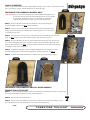
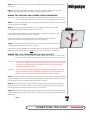
I N S TA L L AT I O N
t o m b s t o n e t a i l l i g h t 4992
Fi t s ‘ 9 9 – ’ 0 3 Roa d Star, ‘99–u p V S tar 1100 Cl assi c, and ‘98–u p V Star 650
c l a s si c , ’ 0 3 – up V ulcan 1600 C l assic and custom a pp l icat ions
Part #
404991
404992
404992B 404990G 904991 Included
1
1
1
1
1
1
1
3
3
2
2
3
1
1
1
1
1
3
2
1
1
1
5
5
3
1
1
Tombstone taillight bar
Light bar gasket, Kawasaki
Light bar gasket, Yamaha
L.E.D. housing
L.E.D. board
L.E.D. cover
Chrome license plate bracket
0.280 x 1-1/4” X .060 Fender washer
1/4”–20 x 1-1/4” Ribbed neck bolt
8–32 x 1/2” PHPS
1/4“–20 x 5/8” SHCS
1/4“–20 Nylock nut
Taillight lens
L.E.D. board assembly
Lens housing
Taillight housing
Flat gasket
8–32 x 9/16” PHPS
1/4“–20 Nylon insert
1/4“–20 x 5/8” Ribbed neck DSHB
1/4“–20 x 1-3/8” Ribbed neck DSHB
Wire Tap and Splice Kit, including:
T-Tap Female Quick Slide Scotch Lock connector
Male Scotch Lock Connector
4” Cable tie
Dielectric grease
Installation Instructions
Please read and understand entire instructions before starting installation.
Thank you for choosing Kuryakyn!
WARNING! SHOCK HAZARD! Disconnect the battery before working with
any electrical connections.
Attention!This kit contains components to fit multiple manufacturers’ models; be sure
to use the correct components for specific installations. The rubber mounting
pad that is pre-mounted to the Tombstone Taillight is designed for Yamaha
applications. We suggest replacing the rubber mounting pad with the
additional pad supplied in the kit for installation on a Kawasaki Vulcan 1600
Classic.
ATTENTION!It is the installer’s responsibility to ensure all fasteners (including pre-assembled)
are tightened before operation of the motorcycle. Kuryakyn will not warranty
components lost due to improper installation. Periodic maintenance may be
required.
4992-15HD-0507
-cont.-
CUSTOMER SERVICE
877.370.3604 (toll free)
INSTALLATION QUESTIONS
[email protected]
or call 715.247.2983
LIMITED WARRANTY
Küryakyn warrants that any Küryakyn products sold
hereunder, shall be free of defects in materials and
workmanship for a period of one (1) year from the
date of purchase by the consumer excepting the following provisions:
• Küryakyn shall have no obligation in the event
the customer is unable to provide a receipt showing
the date the customer purchased the product(s).
• The product must be properly installed,
maintained and operated under normal conditions.
• Küryakyn makes no warranty, expressed or
implied, with respect to any gold plated products.
• Küryakyn shall not be liable for any consequential
and incidental damages, including labor and
paint, resulting from failure of a Küryakyn product,
failure to deliver, delay in delivery, delivery in nonconforming condition, or for any breech of contract or
duty between Küryakyn and a customer.
• Küryakyn products are often intended for use
in specific applications. Küryakyn makes no
warranty if a Küryakyn product is used in
applications other than intended.
• Küryakyn electrical products are warranted for one
(1) year from the date of purchase by the consumer.
Components of Küryakyn products containing L.E.D.s
will be warranted for defects in materials and
workmanship for 3 years from the date of purchase.
• Küryakyn makes no warranty of any kind in regard
to other manufacturer’s products distributed by
Küryakyn. Küryakyn will pass on all warranties made
by the manufacturer and where possible, will expedite
the claim on behalf of the customer,
but ultimately, responsibility for disposition of the
warranty claim lies with the manufacturer.
ABOUT OUR CATALOG
You’ll find all our innovations for H-D, GL and
Metric Cruisers in our annual catalogs. Order online
today–select the ”CATALOGS” icon. Each Küryakyn
product comes with a Proof-of-Purchase good for a
complimentary catalog. Details in packaging.
Be sure to ask your local dealer about other
Küryakyn products, the motorcycle parts and accessories designed for riders by riders.
©2005 Küryakyn USA All Rights reserved.
Tools Suggested
®
Metric sockets, metric Allen wrenches, standard Allen wrenches, 7/16” socket or combination wrench,
pliers, wire stripper/crimper, dead blow hammer (for Kawasaki only).
PIC.1
procedure For Kawasaki Models Only
Attention!The press fit forward mounting bolts on the taillight backing plate must
be removed and re-positioned for Kawasaki applications. Do not attempt
to perform this installation if you are not confident in your ability to
complete all steps in the procedure; consult a trained technician.
STEP 1 Remove the nuts and washers from the bolts; remove the backing plate
from the taillight assembly. See PIC.1. Save the hardware.
STEP 2 The two top press fit bolts must be removed from the backing plate. Place
the top 1/3 of the backing plate, with the bolts heads facing down, over a wood block
covered with a soft cloth.
PIC.2
STEP 3 Thread the nuts onto the two top bolts until the nut is even with the end of the bolt
shaft. See PIC.2.Using a soft-faced dead blow hammer, tap out the two top bolts.
STEP 4 Remove the nuts from the loose bolts and turn the backing plate over. Place the top
1/3 of the backing plate back on the covered wood block and insert the threaded shaft of the
bolts into the upper holes. See PIC.3. Using the dead blow hammer, tap the bolt heads squarely
to seat the bolts into the backing plate.
STEP 5 Install the backing plate onto the taillight and tighten the two fasteners to secure.
Install the rubber gasket over the three mounting bolts in the backing plate. See PIC.4.
STEP 6 Continue the taillight installation as outlined in the appropriate sections below.
PIC.4
PIC.3
PROCEDURE FOR KAWASAKI AND ALL OTHER MODELS
Remove Stock Taillight
STEP 1 The stock taillight assembly is held in place with nuts located under the fender. Loosen the nuts
and remove the taillight assembly. Disconnect the wiring harness.
Page
STEP 2 Remove the license plate bracket.
STEP 3 The stock turn signal light bar is held in place with bolts located under the fender. Loosen
the bolts and remove the turn signal light bar. Disconnect the wiring harness.
-cont.-
2
t o m b s t o n e ta i l l i g h t
INSTALLATION
STEP 4 Feed the wires for the new Tombstone Taillight through the rubber gasket then through
®
the fender.
STEP 5 Mount the new taillight assembly to the fender using the existing holes. Fasten the
taillight using a supplied fender washer and 1/4–20 Nylock nut for each bolt.
Wiring the Taillight and License Plate Illuminator
Attention!These instructions are applicable to multiple manufacturers’ models; be sure to verify
the correct wiring connections using a factory service manual for your specific model.
STEP 6 Route the taillight and license plate illuminator wires under the fender and seat, following
the wiring from the stock taillight.
STEP 7 Connect the ground wire (black) on the new taillight assembly to the ground
PIC.5
wire on the bike using the supplied Scotch Lock connectors.
Connect the run function wire (red) on the new taillight assembly to the run function wire
on the bike using the supplied Scotch Lock connectors.
Connect the brake function wire (white) on the new taillight assembly to the brake
function wire on the bike using the supplied Scotch Lock connectors.
STEP 8 Connect the license plate illuminator power wire (red) to the run function wire
on the bike using the supplied Scotch Lock connectors.
Connect the license plate illuminator ground wire (black) to the ground wire on the bike using the
supplied Scotch Lock connectors. See PIC.5 for proper use of the Scotch Lock connectors.
Wiring the L.E.D. Turn Signal (P/N 2366 or 2367)
Attention!These instructions are applicable to multiple manufacturers’ models; be sure to verify
the correct wiring connections using a factory service manual for your specific model.
Caution! LED circuit boards are polarity sensitive! Use a test light to check the
polarity of the bike’s wiring before connecting the LED circuit board.
Küryakyn is not responsible for damage to the LED circuit board
caused by reversed polarity.
Caution! Use a test light to verify wire functions before connecting the LED
circuit board to non-stock wiring. Küryakyn is not responsible for
damage to the LED circuit board caused by non-stock wiring.
STEP 9 Connect the right turn signal ground wire (black) to the bike right turn signal ground wire
using the supplied Scotch Lock connectors. Connect the right turn signal power wire (brown) to the
bike right turn signal wire using the supplied Scotch Lock connectors.
STEP 10 Connect the left turn signal ground wire (black) to the bike left turn signal ground wire
using the supplied Scotch Lock connectors. Connect the left turn signal power wire (violet) to the
bike left turn signal wire using the supplied Scotch Lock connectors.
STEP 11 Reconnect the battery. Start the bike and test for proper function. If the turn signals flash
rapidly, or exhibit any other abnormal operation, you will need to install the load equalizer included
with the kit.
-cont.-
Page
3
t o m b s t o n e ta i l l i g h t
INSTALLATION
Install the Load Equalizer
Remove the seat. Locate the wiring harness from the rear fender. Connect the black wire from the
load equalizer to the right turn signal ground wire in the wiring harness. Connect one violet wire
from the load equalizer to the right turn signal power wire in the wiring harness and one violet wire
from the load equalizer to the left turn signal power wire in the wiring harness.
®
Caution! Do not secure the load equalizer to the control module! Excess
heat from the load equalizer could damage the control module.
Caution! Always install the load equalizer upstream of any existing aftermarket multifunction control modules. Do not install a load equalizer between a module and the turn signals as this will overload
the module. Overloading will damage the module and create a fire
hazard!
Caution! Load equalizers generate heat when in use. Avoid using the turn
signals for an extended period of time, otherwise the load equalizer
will overheat. Never operate the four-way flashers unless you first
remove the load equalizer. Overheating damages the load equalizer
causing loss of turn signal operation and could create a fire hazard!
STEP 12 Use the supplied 4” cable ties to secure the wires away from moving parts.
Wiring the Halogen Turn Signal (P/N 2336 or 2337)
Attention!These instructions are applicable to multiple manufacturers’ models; be sure to verify
the correct wiring connections using a factory service manual for your specific model.
STEP 13 The halogen turn signals use a chassis ground; you must ground the taillight housing in
order for the turn signals to operate. Create a ground strap by crimping one end of a 5” length of 16
gauge ground wire (not included) with a 1/4” ring terminal connector (not included), crimp the other
end with a supplied Scotch Lock connector (male)
STEP 14 Connect the ring terminal to one of the top two nuts that secure the taillight assembly to
the fender. Connect the Scotch Lock connector from the ground strap to a Scotch Lock connector
(female) crimped to the existing ground wire on the bike.
STEP 15 Connect the right turn signal power wire (black) to the right turn signal power wire on the
bike.
STEP 16Connect the left turn signal power wire (black) to the left turn signal wire on the bike.
STEP 17 Reconnect the battery. Start the bike and test for proper function.
STEP 18 Use the supplied 4” cable ties to secure the wires away from moving parts.
Ride On!
Page
4
t o m b s t o n e ta i l l i g h t
INSTALLATION