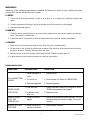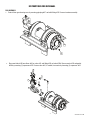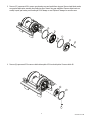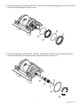
1
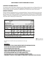
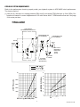
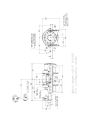
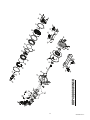
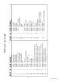
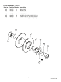
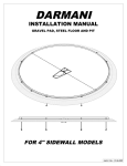
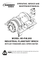
OPERATING, SERVICE AND
MAINTENANCE MANUAL
MODEL HD-P40,000
INDUSTRIAL PLANETARY WINCH
WITH AIR TENSIONER AND 2 SPEED MOTOR
CAUTION: READ AND UNDERSTAND THIS MANUAL BEFORE INSTALLATION
AND OPERATION OF WINCH. SEE WARNINGS!
TABLE OF CONTENTS
INTRODUCTION ............................................................................................................... 1
WARRANTY INFORMATION ............................................................................................ 1
SPECIFICATIONS ............................................................................................................ 1
WARNINGS ....................................................................................................................... 1
HYDRAULIC SYSTEM REQUIREMENTS ........................................................................ 2
PERFORMANCE CHARTS ............................................................................................... 2
WINCH OPERATION ........................................................................................................ 3
CLUTCH OPERATION ...................................................................................................... 3
CABLE INSTALLATION .................................................................................................... 3
MAINTENANCE ................................................................................................................ 4
TROUBLE SHOOTING GUIDE ......................................................................................... 4
INSTRUCTIONS FOR OVERHAUL ...............................................................................5-9
MOUNTING CONFIGURATIONS ................................................................................... 10
DIMENSIONAL DRAWING ............................................................................................. 11
PARTS LIST AND PART DRAWING .........................................................................12-15
LIMITED WARRANTY ....................................................................................... Back cover
RAMSEY HYDRAULIC PLANETARY WINCH MODEL HD-P40,000
PLEASE READ THIS MANUAL CAREFULLY
This manual contains useful ideas in obtaining the most efficient operation from your Ramsey Winch, and
safety procedures one needs to know before operating a Ramsey Winch. Do not operate this winch until
you have carefully read and understand the "WARNINGS" and "OPERATION" sections of this manual.
WARRANTY INFORMATION
Ramsey Winches are designed and built to exacting specifications. Great care and skill go into every winch
we make. If the need should arise, warranty procedure is outlined on the back of your self-addressed postage paid warranty card. Please read and fill out the enclosed warranty card and send it to Ramsey Winch
Company. If you have any problems with our winch, please follow instructions for prompt service on all warranty claims. Refer to back page for limited warranty.
Rated Line Pull (lbs.).........................................................................40,000
(Kgs.)..............................................................................18,100
Gear Reduction................................................................................51.35:1
Weight (without cable)...............................................740 lb. (336.36 Kgs.)
LAYER OF CABLE
1
2
3
4
5
6
*Rated line pull Lbs. 40,000 33,500 28,800 25,300 22,500 20,300
per layer
Kg. 18,100 15,100 13,000 11,400 10,200 9,200
25
7
55
16
95
28
135
41
185
56
235
71
FPM
17
MPM 5.2
20
6.1
23
7.0
27
8.2
30
9.1
33
10.1
*Cable capacity Ft.
M.
*Line speed
(at 20 GPM)
* These specifications are based on recommended wire rope of .75 inch
dia. EIPS cable and 9.6 cu.in./Rev. motor.
NOTE: The rated line
pulls shown are for
the winch only. Consult the wire rope manufacturer for wire rope
ratings.
WARNINGS:
CLUTCH MUST BE TOTALLY ENGAGED BEFORE STARTING THE WINCHING OPERATION.
DO NOT START WINCH MOTOR BEFORE ENGAGING CLUTCH.
DO NOT DISENGAGE CLUTCH UNDER LOAD.
STAY OUT FROM UNDER AND AWAY FROM RAISED LOADS.
STAND CLEAR OF CABLE WHILE PULLING. DO NOT TRY TO GUIDE CABLE.
DO NOT EXCEED MAXIMUM LINE PULL RATINGS SHOWN IN TABLE.
DO NOT USE WINCH TO LIFT, SUPPORT, OR OTHERWISE TRANSPORT PEOPLE.
A MINIMUM OF 5 WRAPS OF CABLE AROUND THE DRUM BARREL IS NECESSARY TO HOLD THE LOAD.
1
HYDRAULIC SYSTEM REQUIREMENTS
Refer to the performance charts to properly match your hydraulic system to HDP-40000 winch performance.
The charts consist of:
(1) Line pull (lb.) first layer vs. working pressure (PSI) and (2) Line speed (FPM) first layer vs. flow (GPM). Performance is based on a motor displacement of 9.6 cubic inches with 17 GPM maximum flow rate. See page
10 for motor port size.
TYPICAL LAYOUT
PORT CONTROL
WITH BRAKE RELEASE SHUTTLE
HIGH PRESSURE LINE
(.50 I.D. MINIMUM)
LOW PRESSURE LINE
(.75 I.D. MINIMUM)
MOTOR
BRAKE
PORT
A
B
MAX. FLOW &
PRESSURE AT
RATED LOAD:
15 GPM
2500 PSI
40000
35
35000
30
LINE SPEED (Ft/Min)
LINE PULL (Lbs.)
3 POSITION
4 WAY VALVE
(MOTOR SPOOL)
30000
25000
20000
15000
10000
25
20
15
10
5
0
0
500
1000 1500 2000 2500
DELTA P @ MOTOR (PSI)
2800
2
SYSTEM
RELIEF
0
5
10
15
17
FLOW (GPM)
914243-0711-D
WINCH OPERATION
The best way to get acquainted with how your winch operates is to make test runs before you use it. Plan
your test in advance. Remember, you hear your winch, as well as see it operate. Learn to recognize the
sounds of a light steady pull, a heavy pull, and sounds caused by load jerking or shifting. Gain confidence in
operating your winch and its use will become second nature with you.
The uneven spooling of cable, while pulling a load, is not a problem, unless there is a cable pileup on one end
of drum. If this happens, reverse the winch to relieve the load and move your anchor point further to the center of the vehicle. After the job is done you can unspool and rewind for a neat lay of the cable.
CLUTCH OPERATION
To engage clutch:
1. Move the clutch control valve to the “clutch engaged” position.
2. Anytime the temperature is below freezing, run the motor in the “cable out” direction only until the
drum starts to turn. In extreme cold temperatures (below 0˚ F/-18˚ C), pull out on the cable by hand
only until the drum starts to turn.
3. Wait at least 3 seconds for the clutch to fully engage, after which the winch is ready to winch in the
cable.
WARNING: Do not attempt to engage the clutch by first running the winch motor and then moving the
clutch control valve to the "clutch-engaged" position while the motor is running. Do not start picking up
the load at the same time the clutch is being engaged.
To disengage clutch:
1. Run the winch in the "cable out" direction until the load is off the cable.
2. Move the clutch control valve to the "clutch-disengaged" position.
3. The cable may now be pulled off by hand.
CABLE INSTALLATION
1. Unwind cable by rolling it out along the ground to prevent kinking. Securely wrap end of wire rope, opposite hook, with plastic or similar tape to prevent fraying.
2. Insert the end of cable, opposite hook end, into the hole in drum barrel. Secure cable to drum barrel,
using setscrew furnished with winch. TIGHTEN SETSCREW SECURELY.
3. Carefully run the winch in the “reel-in” direction. Keeping tension on end of cable, spool all the cable
onto the cable drum, taking care to form neatly wrapped layers.
3
914243-0711-D
MAINTENANCE
Adhering to the following maintenance schedule will keep your winch in top condition and performing as it should with a minimum of repair.
A. WEEKLY
1. Check the oil level and maintain it to the oil level plug. If oil is leaking out, determine location and
repair.
2. Check the pressure relief plug in the gear housing cover. Be sure that it is not plugged.
3. Lubricate cable with light oil.
B. MONTHLY
1. Check the winch mounting bolts. If any are missing, replace them and securely tighten any that are
loose. Use grade 5 or better bolts.
2. Inspect the cable. If the cable has become frayed with broken strands, replace immediately.
C. ANNUALLY
1. Drain the oil from the winch annually or more often if winch is used frequently.
2. Fill the winch to the oil level plug with clean kerosene. Run the winch a few seconds with no load in
the reel in direction. Drain the kerosene from the winch.
3. Refill the winch to the oil level plug with all-purpose SAE 75W-90 synthetic gear oil.
4. Inspect frame and surrounding structure for cracks or deformation.
TROUBLESHOOTING GUIDE
CONDITIONS
POSSIBLE CAUSE
CORRECTION
1. Seals damaged or
worn.
1. Replace seal.
2. Too much oil.
2. Drain excess oil. Refer to OPERATION.
3. Damaged gaskets.
3. Replace gaskets.
1. Low flow rate
1. Check flow rate. Refer to HYDRAULIC SYSTEMS performance chart page 2.
2. Hydraulic motor
worn out.
2. Replace motor.
CABLE DRUM
WILL NOT
FREESPOOL
1. Clutch not disengaged
1. Check air pressure to clutch cylinder: 100 PSI
Minimum required. Refer to page 10 for port
location.
BRAKE WLL NOT
RELEASE
1. Brake line disconnected or blocked.
1. Check brake function.
OIL LEAKS FROM
WINCH
WINCH RUNS
TOO SLOW
4
914243-0711-D
INSTRUCTIONS FOR OVERHAUL
DIS-ASSEMBLY
1. Drain oil from gear housing cover by removing pipe plug #37 and relief fitting #32. Remove tensioner assembly.
32
37
2.
Disconnect tube #40 from elbow #43 on valve #41 and fitting #29 on brake #30b. Remove motor #33 and gasket
#30a by removing (2) capscrews #22. Remove valve #41, if needed, from motor by loosening (4) capscrews #16.
16
43
41
40
22
33
30a
5
914243-0711-D
3. Remove (12) capscrews #18 to remove gear housing cover and gasket from ring gear. Remove input thrust washer,
sun gear and input carrier assembly from inside ring gear. Remove ring gear and gasket. Remove output carrier assembly. Inspect gear housing cover bushing #15 for damage or wear. Replace if damaged or excessive wear.
31
42
31
15
5
18
4. Remove (8) capscrews #20 to remove clutch retainer plate #10 from clutch piston. Remove clutch #9.
9
10
20
6
914243-0711-D
5. Remove clutch housing #27 with piston #28 inside. To remove piston from clutch housing apply air to 1/8” port. Remove orings #28 and #35 and inspect for damage or wear.
35
27
36
28
6. Remove (9) springs #39, thrust washer #26, gasket #31, output shaft #12 and spacer #13 from gear end bearing. Inspect output shaft bushing #14 for damage or wear. Replace if damaged or excessive wear.
26
13
12
14
31
39
7
914243-0711-D
7. Remove winch tie bars #2 and #3 by removing (8) capscrews #19, (8) lock washers # 24, and (4) shoulder bolts
#25. Pull gear end bearing #7 from drum assembly #1.
2
24
25
25
19
3
24
19
7
25
24
19
25
24
19
8. Pull drum assembly #1 from end bearing #6. Remove quad-rings #34 from grooves in drum bushings. Remove input
shaft #11 from end bearing. Examine splined ends of input shaft for signs of wear, replace if damaged. Examine drum
assembly #1 for signs of wear.
6
8
4
11
23
38
34
1
34
8
914243-0711-D
9. If splines inside drum driver #102 are damaged, drum driver must be replaced. Remove drum driver by unscrewing (8)
capscrews #105. If bushings show signs of wear, replace by pressing old bushings from drum #101 and removing orings from grooves in drum and drum driver. Place well oiled o-rings #106 into driver and drum. Place well oiled o-ring
#107 on outside of driver. Press bushings #104 into drum driver until flange is flush and #103 is flush against drum.
106
101
107
102
103
106
104
105
10. Remove brake assembly screws #17 from brake #36a attaching brake to end bearing #6. Remove coupling #4 and
gasket #36e from end bearing. Take note of mounting configuration for proper mounting of parts during re-assembly.
17
30c
30e
6
30b
9
91424
10
914243-0711-D
R.H. MOUNTING
CONFIGURATION
L.H. MOUNTING
CONFIGURATION
WINCH MOUNTING CONFIGURATION
11
914243-0711-D
13
914243-0711-
22
30a
17
43
30b
30
29
40
30c 30e
38
4
HDP 40,000 WINCH
33
41
16
13
12
6
14
31
19
8
26
25
11
39
24
3
25
36
19
34
28
24
23
1
9
20
34
10
35
2
27
24
7
19
31
25
24
42
25
15
19
31
37
5
32
18
14
914243-0711-D
PARTS LIST - HDP 40,000
DRUM ASSEMBLY - 234191
Item No. Part No. Quantity Description
101
102
103
104
105
106
107
332197
332226
412078
412079
414978
462043
462075
1
1
1
1
8
2
1
DRUM‐CABLE
DRIVER‐DRUM
BUSHING‐DRUM
BUSHING‐DRUM
CAPSCREW‐5/8‐18NC X 1 1/4LG, SOC HD
O‐RING‐AS‐568‐348, 3/16 X 4 3/4 X 4 3/8
O‐RING‐AS‐568‐354, 3/16 X 5 1/2 X 5 1/8
106
101
107
102
103
106
104
105
15
914243-0711-D
CABLE TENSIONER (OVERWOUND) - 299744
Item No. Part No. Quantity Description
201
265102
1
LEVER ARM
202
304174
1
BAR
203
346046
1
PIVOT PIN
205
408362
1
BRACKET
205
414278
4
CAPSCREW-3/8-16NCX3/4LG,HXHD,GR.5, ZINC PLATED
206
414316
2
CAPSCREW-3/8-16NCX1 1/4,HXHD,GR.5, ZINC PLATED
207
418045
2
NUT-3/8-16NC HEX REG GR.5, ZINC PLATED
208
418098
1
NUT-3/4-16NF HEX JAM
209
418177
2
LOCKWASHER-3/8 MED SECT,ZINC PLATED
210
418223
4
WASHER-1/2 USS FLAT,ZINC PLATED
211
424005
2
COTTER PIN
212
432033
1
FITTING-ELBOW
213
433029
1
ACTUATOR
214
418069
2
NUT - 1/2 - 13 UNC
215
420005
1
ANCHOR BOLT
215
205
205
214
210
202
201
213
206
211
210
204
203
211
209
210
207
210
214
208
212
16
914243-0711-D
LIMITED WARRANTY
RAMSEY WINCH warrants each new RAMSEY WINCH to be free from defects in material and workmanship for a period of
one (1) year from date of purchase.
The obligation under this warranty, statutory or otherwise, is limited to the replacement or repair at the Manufacturer's factory, or
at a point designated by the Manufacturer, of such part that shall appear to the Manufacturer, upon inspection of such part, to have
been defective in material or workmanship.
This warranty does not obligate RAMSEY WINCH to bear the cost of labor or transportation charges in connection with the replacement or repair of defective parts, nor shall it apply to a product upon which repair or alterations have been made, unless authorized by Manufacturer, or for equipment misused, neglected or which has not been installed correctly.
RAMSEY WINCH shall in no event be liable for special or consequential damages. RAMSEY WINCH makes no warranty in
respect to accessories such as being subject to the warranties of their respective manufacturers.
RAMSEY WINCH, whose policy is one of continuous improvement, reserves the right to improve its products through changes in
design or materials as it may deem desirable without being obligated to incorporate such changes in products of prior manufacture.
If field service at the request of the Buyer is rendered and the fault is found not to be with RAMSEY WINCH's product, the Buyer
shall pay the time and expense to the field representative. Bills for service, labor or other expenses that have been incurred by the
Buyer without approval or authorization by RAMSEY WINCH will not be accepted.
See warranty card for details.
RAMSEY WINCH COMPANY
Post Office Box 581510 Tulsa, Oklahoma 74158-1510
Telephone: (918) 438-2760 FAX: (918) 438-6688
OM-914243-0909-D