1
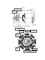
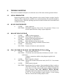
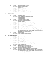
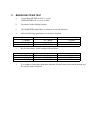
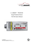
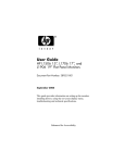
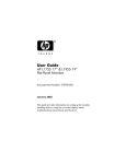
TRANSFORMER REGULATED
BRUSHLESS GENERATOR
INSTALLATION, OPERATION, AND SERVICE MANUAL
GPN015
TABLE OF CONTENTS
1.
INTRODUCTION
3
2.
GENERAL DATA
3
3.
INITIAL INSPECTION
4
4.
SAFETY GUIDELINES
4
5.
INSTALLATION
5
5.1
5.2
5.3
5.4
LOCATION/ENVIRONMENT:
BASE MOUNTING:
MECHANICAL MOUNTING:
ELECTRICAL CONNECTIONS:
5
5
5
8
6.
INITIAL START-UP:
8
7.
ADJUSTING THE VOLTAGE
9
7.1
7.2
7.3
8.
NO-LOAD VOLTAGE ADJUSTMENT
FULL-LOAD VOLTAGE ADJUSTMENT
ADJUSTING RESISTORS
TROUBLE SHOOTING
8.1
8.2
8.3
8.4
8.5
8.6
8.7
VISUAL EXAMINATION
NO VOLTAGE PRODUCED
WILL NOT HOLD VOLTAGE:
FULL VOLTAGE AT NO LOAD, VOLTAGE DROPS AT FULL LOAD:
LOW VOLTAGE
VOLTAGE TOO HIGH
UNCONTROLABLE VOLTAGE
9
9
9
10
10
10
10
10
11
11
12
9.
FLASHING THE FIELD
12
10.
CHECKING DIODES IN THEARMATURE
13
11.
BRIDGE RECTIFIER TEST
14
12.
MAINTENANCE AND REPAIR
15
12.1
12.2
13.
PERIODIC CLEANING AND INSPECTION:
CLEANING:
SPARE PARTS
15
15
15
INSTRUCTIONS
TRANSFORMER REGULATED BRUSHLESS GENERATOR
1.
INTRODUCTION
Thank you for choosing a MARATHON ELECTRIC transformer regulated generator.
We have been in the business of building quality generators since 1894. Taking advantage
of the latest technical advancements, to assure you the most reliable, efficient, trouble free
generator available anywhere.
Please read the installation and service sections of this manual carefully. A clean
environment and proper installation are as critical to generator performance as is the
engineering of the internal components. If you have any difficulty in installing or servicing
your Fidelity generator our service and technical staff will be happy to assist you. We are
confident that if these guidelines are taken, you will get many years of reliable service from
your MARATHON ELECTRIC generator.
2.
GENERAL DATA
Construction
Speed:
Fan cooled
40 degrees C.
Insulation
Brush-less Rotating Field
60 hertz
1800 rpm
50 hertz
1500 rpm
Max. Ambient Temp.
Class "H"
NOTE: If the generator is operated at 1500 RPM. The voltage and kW rating will be 5/6
of the 1800 RPM rating. Consult the manufacturer if a higher voltage or kW rating is
required at 50 hertz (1500 RPM).
3.
INITIAL INSPECTION
Your MARATHON generator has been carefully inspected and tested before leaving the
factory. However, it is wise to examine the unit before installation.
3.1
4.
Carefully unpack the generator and examine for any damage. If there is any, file a
damage claim with the shipper or agent immediately. Save all packing materials for
inspection by agent.
SAFETY GUIDELINES
In order to avoid personal injury and to prevent damage to equipment, it is imperative that
all the safety precautions listed below are followed when operating this equipment.
4.1
READ THE OPERATIONS MANUAL CAREFULLY; familiarize yourself with
the equipment before operating. Consider the limitations and potential hazards of
electrical equipment before operation.
4.2
NEVER START THE GENERATOR WITH AN ELECTRICAL LOAD
APPLIED.
4.3
PROTECT YOURSELF AGAINST ELECTRICAL SHOCK. Never operate the
generator, or handle any electrical equipment while wet, barefoot or while it is
raining.
4.4
MAINTAIN ALL ELECTRICAL CORDS IN GOOD CONDITION. Worn,
frayed or bare wires will cause severe electrical shock.
4.5
ALWAYS DISCONNECT ALL ELECTRICAL LOADS BEFORE WORKING
ON THE GENERATOR.
4.6
ALWAYS PROVIDE ADEQUATE VENTILATION. Engines consume oxygen
and give off deadly monoxide gases.
5.
INSTALLATION
5.1
Location/Environment:
The engine-generator set must be installed in a protected environment. With minimal
exposure to fumes, moisture, dust and dirt.
THE AMBIENT AIR TEMPERATURE MUST NOT EXCEED 40 C,
(104 F) CONTINUOUS DUTY.
a.
DO NOT obstruct the generator intake and outlet air passages.
b.
Provide sufficient air circulation around the set to remove engine heat and to
provide ample generator cooling.
c.
Hot air from the radiator or engine should not pass through the generator.
d.
Check the mounting surface to be sure that it is rigid enough to keep vibration
and noise to a minimum.
5.2
Base Mounting:
Generator must be mounted securely. Use shims as necessary under generator feet to
be sure that feet are uniformly supported before tightening hold-down bolts. If the
generator is not uniformly supported, the frame could become distorted resulting in
noise and vibration that could damage the generator.
5.3
Mechanical Mounting:
To mount a single-bearing generator to an engine, See FIG. 5.1
a.
b.
c.
d.
e.
f.
g.
h.
i.
j.
Disconnect the positive (+) terminal from the battery.
Place a jack or other support under the engine flywheel.
Remove the control box cover from the back of the generator.
Detach the ground lead "Q"(-) and "R"(+) lead from the rotor, on the
exciter armature. See FIG. 5.2.
Remove the armature fastening bolt from the center of the shaft. (Mark
the position of the armature so it can be replaced in the same position).
Remove armature from shaft.
(CAUTION: Do not damage the laminations or windings).
Remove the fan cover.
After the armature is removed, the rotor, shaft, and drive disk assembly can
be pulled from the frame.
(CAUTION: Do not scratch or cut the copper stator windings when
removing rotor).
Use a strap around the generator rotor and shaft assembly and support from
hoist.
DO NOT LOOSE the bearing anchor when the bearing is removed from
exciter end bracket. See FIG. 5.3.
FIGURE 5.1
Exciter field and
end bracket
Exciter
Armature
Figure 5.2
Exciter
Armature
Heat Sink
"Q" (-) lead
Ground
Diode
Rectifier
Six Total
Exciter
Field
Suppressor
Mounting Bolt
"R" (+) Lead
Figure 5.3
k.
l.
m.
n.
Bolt the rotor and drive disk to the engine flywheel, using the proper size lock
washers and SAE grade 8 bolts.
Push the generator frame assembly carefully back over the rotor. Replace the
bearing anchor and carefully align the groove in the bearing with the bearing
anchor before the bearing enters the bracket.
Mount the frame assembly to the engine flywheel housing with the proper
size bolts, lock washers and nut.
Remount the fan cover and hood.
o.
To reassemble the exciter armature, pull the rotor leads through the opening
in the armature spider. Turn the armature until it slips over the pins in the
shaft. (CAUTION: Do not pinch rotor leads).
p.
Reassemble the armature to the shaft with the bolt and lock washer using
Lock-tight. Use a 9/16" socket on the torque wrench and torque to 25-ft. lb.
Reconnect the "Q" and "R" leads to the proper connections. See FIG. 5.2.
Reconnect all incoming power leads to their proper connections, as shown on
wiring diagram.
Return control box cover.
Remove the jack support from under engine flywheel housing.
Reconnect the positive (+) battery terminal lead.
q.
r.
s.
t.
u.
5.4
Electrical Connections:
The proper electrical connections required for your
1-PH or 3-PH generator can be found on the Schematic Wiring Diagram attached to
the back of this manual.
NOTE: BE SURE THAT ALL ELECTRICAL CONNECTIONS ARE
CORRECT BEFORE STARTING THE GENERATOR.
6.
INITIAL START-UP:
6.1
Carefully inspect the unit before start-up.
a.
Be sure that all electrical connections are correct.
b.
Look for pinched leads.
c.
Tighten all connections securely.
d.
All bolts should be securely mounted.
e.
Rotate the shaft by turning the armature bolt. The shaft and rotor assembly is
balanced and should turn freely.
f.
Start engine.
g.
Check vibration. If excessive, check all mechanical connections.
6.2
The generator voltage is adjusted at the factory to a specified speed; however, it is advisable
to verify upon installation. To supply 60 HZ, the speed should be 1800 to 1860 RPM at no
load and should not fall below 1800 RPM by more than one percent at full load.
To supply 50 HZ, the speed should be 1500 to 1550 RPM at no load and 1500 RPM at full
load. The generator voltage should build to its rated value within 5 seconds after rated speed
is attained. If voltage does not build, the cause may be loss of residual magnetism in the
exciter field, due to improper installation. See TROUBLE SHOOTING, SECTION 8, of
this manual for more information. To be sure that the generator voltage will always build,
operate the generator at full load before installing in service.
6.3
Observe and record the generator voltage at no load and at full load. Immediately after start-up
(cold) and after 30 minutes of full load (hot), the voltage can be adjusted to optimum values
at no load and full load. Test at actual load if possible.
6.4
If the voltage cannot be adjusted, see TROUBLE SHOOTING, SECTION 8, of this manual.
6.5
After operating for 30 minutes at full load, check temperature rise. If excessive,
examine the generator for obstructed air flow, hot air recirculating into the generator,
or bypassed air (air not pulled through generator).
6.6
Examine ratings and actual load applied to determine if the generator rating may be
too low for the load applied.
6.7
CONTINUOUS DUTY. FOR OPERATION AT AMBIENT TEMPERATURES ABOVE
40o, DERATE kW RATING 2 PERCENT FOR EACH DEGREE C. ABOVE 40o C. For
operations at high altitudes, ratings must be derated 2 percent for each 1000-ft. above sea
level. Frame temperatures above 60o C. (140o F.) are too high
7.
ADJUSTING THE VOLTAGE
A transformer-regulated generator is designed to have superior motor starting compared to
other types. The regulation is within (+/- 5%) of rated loads.
7.1
NO-LOAD VOLTAGE ADJUSTMENT
The no-load voltage can be adjusted by adding or removing SHIM, located between the top
laminations.
ADD SHIM TO INCREASE THE NO-LOAD VOLTAGE.
REMOVE SHIM TO REDUCE THE NO-LOAD VOLTAGE.
The SHIM should be made of a thin non-conducting material such as Mylar or Polyester
paper .003 - .015 in. thick. Pounding on the top laminations with a soft mallet to reduce the
air gap can do reducing the voltage by 1 or 2 volts. DO NOT increase the no-load voltage
by separating the laminations without filling in the gap with SHIM material. Magnetic forces
in the transformer will close the gap and reduce the no-load voltage.
7.2
FULL-LOAD VOLTAGE ADJUSTMENT
The full-load voltage can be adjusted by changing the number of transformer
secondary turns. This will also effect the no-load voltage. (See table below to
increase voltage or follow in reverse to decrease voltage).
Bridge Rectifier
"AC"
"AC"
"AC"
"AC"
7.3
Transformer lead
"X"
"4"
"X"
"X"
Stator lead to Transformer lead
"W" or "U1" to "32"
"W" or "U1" to "32"
"W" or "U1" to "24"
"W" or "U1" to "24"
NOTES
Minimal increase
Maximum increase
ADJUSTING RESISTORS
Adjusting the voltage on generators with resistors will be different from what was
just explained above.
ADD SHIM TO REDUCE FULL-LOAD VOLTAGE.
REMOVE SHIM TO INCREASE FULL-LOAD VOLTAGE.
No-load voltage is adjusted by changing the resistance in the VR1 resistors.
INCREASE VOLTAGE BY DECREASING RESISTANCE. Decrease the
distance between the leads on the VR1 resistor.
DECREASE VOLTAGE BY INCREASING RESISTANCE. Increase the
distance between the leads on the VR1 resistor.
8.
TROUBLE SHOOTING
This section is intended to help the user isolate the cause of the most common generator failures.
8.1
VISUAL EXAMINATION
Inspect the generator visually. Many problems are the result of simple oversight. Look for
obvious evidence, burned areas, pinched wires, cracked insulation, all connections should be
fastened securely. Check the operating speed and see that the unit has been reassembled and
reconnected correctly.
8.2
NO VOLTAGE PRODUCED
a.
CAUSE:
Faulty suppressor.
SOLUTION: Disconnect suppressor from circuit. Test generator. If there is an
obvious improvement in voltage, replace suppressor.
8.3
WILL NOT HOLD VOLTAGE:
a.
CAUSE:
Loss of residual magnetism.
SOLUTION: Flash Field, (see SECTION 9).
b.
CAUSE:
Exciter Field has been disconnected.
SOLUTION: Flash Field, (see SECTION 9).
c.
CAUSE:
Rotor shorting out when unit gets hot.
SOLUTION: Check rotor windings for broken or burned wires.
d.
CAUSE:
Pinched leads.
SOLUTION: Examine all lead wires and connections.
8.4
FULL VOLTAGE AT NO LOAD, VOLTAGE DROPS AT FULL LOAD:
a.
CAUSE:
Loose or broken lead wires.
SOLUTION: Check lead wires and connections for broken wires and l loose
connections.
Compare connections with the wiring diagram supplied with
generator.
b.
CAUSE:
Rotor is opened or shorted.
SOLUTION: Measure the resistance between the leads. (See FIG. 8.1. for resistance
values).
c.
CAUSE:
Stator ground or shorted.
SOLUTION: Run generator for five minutes. (Stop immediately if there is smoke or
a hot smell is detected). If the voltage does not build and the generator
is hot, there is a short circuit in the stator windings. Examine for
burred insulation. (DO NOT REMOVE FROM FRAME).
Disconnect leads from terminal board and measure the resistance, T1
& T2/T3 & T4 each should have equal resistance. A lower reading
indicates a short in that winding. Replace stator.
d.
e.
f.
CAUSE:
Exciter field opened or shorted.
SOLUTION: Measure resistance values.
(See FIG. 8.1).
CAUSE:
Defective diodes in the armature.
SOLUTION: See section 10.
CAUSE:
Defective Bridge Rectifier.
SOLUTION: Check polarity. (See test section 11).
8.5
LOW VOLTAGE
a.
CAUSE:
Low engine speed.
SOLUTION: Check engine speed and generator ratings.
1800 rpm/60 hertz
1500 rpm/50 hertz
b.
CAUSE:
Transformer air gap too small.
SOLUTION: Increase air gap in top laminations.
(See SECTION 7).
c.
CAUSE:
Open circuit in transformer secondary winding.
SOLUTION: Check for continuity.
d.
CAUSE:
Resistance in VR1 resistor is too high.
(No-load voltages only, see SECTION 7.3).
SOLUTION: Decrease resistance in VR1 resistor.
e.
CAUSE:
Too many circuits in transformer secondary winding.
SOLUTION: Decrease the number of transformer secondary turns by replacing the
(x) transformer lead to "AC" on the Bridge Rectifier with the (4)
transformer lead. (See SECTION 7.2).
f.
CAUSE:
Defective Diode.
SOLUTION: Check resistance, (see SECTION 10)
8.6
VOLTAGE TOO HIGH
a.
CAUSE:
Fast engine speed.
SOLUTION: Check engine speed.
b.
CAUSE:
Transformer air gap too large.
(No load voltage)
SOLUTION: Reduce air gap in top laminations.
(See SECTION 7).
c.
CAUSE:
Short circuit on transformer secondary winding.
SOLUTION: Check resistance value.
d.
CAUSE:
Resistance in VR1 Resistor too low.
(No load voltages only see SECTION 7.3).
SOLUTION: Increase resistance in VR1 Resistor.
e.
CAUSE:
Not enough circuits in transformer secondary winding.
SOLUTION: Increase the number of transformer secondary turns by replacing the
(4) transformer lead to "AC" on the Bridge Rectifier with the (x)
transformer lead.(See SECTION 7.2).
8.7
UNCONTROLABLE VOLTAGE
a.
CAUSE:
Incorrect engine adjustment.
SOLUTION: Check engine operation, speed, fuel lines and injector.
b.
CAUSE:
Transformer secondary leads shorting.
SOLUTION: Check resistance.
ARMATURE:
FIELD:
10 - 14 ohms
11 - 15 ohms
STATOR:
ohms vary with kW rating, but less than 1.0 OHM per phase.
kW's
ohms
9.
GENERATOR RESISTANCE VALUES
. 470 - .520 Ohms per phase,
5 - 10 kW
.655 - .720 Ohms per phase,
12.5 - 50 kW
8
1.47
10
1.58
12.5
1.73
ROTOR:
15
17.5
1.84
2.00
5 - 10 kW
12.5 - 50 kW
20
2.1
25
2.2
30-50
2.5-3.8
FLASHING THE FIELD
a.
b.
c.
d.
e.
f.
h.
Disconnect all incoming power leads to the generator.
Disconnect the "F" & "C" leads from the Exciter Field.
Connect the "F" lead to the (+) lead of a 12 volt battery.
Connect the "C" lead to the (-) lead of a 12 volt battery.
Start the engine and operate at 1800 rpm/no load.
Check the NO LOAD VOLTAGE, the voltage should be within +/- 10% of rated load.
If the residual voltage is now normal, the transformer is OK and the problem is elsewhere.
10.
CHECKING DIODES IN THEARMATURE
All Fidelity Electric armatures have (6) diode rectifiers arranged in a full wave pattern. Three forward
biased diodes are mounted on a heat sink and three reversed biased diodes are mounted on the
armature hub.
a.
Use a Basic Analog OHMMeter and set to R*1 scale. (OHM meter leads (+) red, (-) black).
b.
Check the diodes as a group with the following connections:
(-) OHM meter lead to "R" terminal on armature hub.
(+) OHM meter lead to "Q" ground.
Diodes are good if the resistance reading is approx. 50 Ohms.
c.
Check for leakage in the diodes by reversing their polarity. Diodes are good if the resistance
reading is infinite.
d.
Resistance values other than those indicated suggest 1 or more faulty diodes. Check each
diode separately to isolate the defective diode.
e.
Disconnect terminals to each diode. Check the Forward Biased Diode "FWD" group first. (3
diodes on heat sink)
(-) OHM meter lead to "R" terminal on armature hub.
(+) OHM meter lead to the (+) on diode (indicated by red dot).
f.
Check for leakage in each diode by reversing polarity.
Resistance = infinite
g.
Check Reversed Biased Diode "RVS" group.
(-) OHM meter lead to "Q" ground on armature hub.
(+) OHM meter lead to the (+) on each diode.
Resistance = infinite
h.
Check for leakage in each diode by reversing polarity.
Resistance = 10 Ohms
NOTE: Resistance values other than those provided indicates that the diode is
defective. Replace. Reconnect terminals to each other.
11.
BRIDGE RECTIFIER TEST
a.
Use an Ohms METER set at DC (+) scale.
(OHM METER leads =(+) red, (-) black.
b.
Disconnect leads to Bridge Rectifier.
c.
The OHMMETER should show a resistance in only one direction.
d.
Make the following connections in a clockwise direction.
(+) meter lead
(+) Bridge
(+) Bridge
(+) Bridge
e.
meter reading
= 0 Ohms
= 0 Ohms
= 0 Ohms
Reverse the polarity for the readings indicated below.
(+) meter lead
"AC" Bridge
(-) Bridge
"AC" Bridge
f.
(-) meter lead
"AC" Bridge
(-) Bridge
"AC" Bridge
(-) meter lead
(+) Bridge
(+) Bridge
(+) Bridge
meter reading
= 10 Ohms
= 50 Ohms
= 10 Ohms
If a resistance reading other than those indicated is found a short exists in that junction and
the rectifier must be replaced.
12.
MAINTENANCE AND REPAIR
12.1
Periodic Cleaning and Inspection:
Clean and inspect the generator after every 200 hours of normal operating time.
If the generator is housed in a harsh environment clean and inspect more frequently. If dirt and
grease is allowed to build-up, the generator will run hotter, lose efficiency and reduce the life
of the generator.
12.2
Cleaning:
Remove all dust, dirt, and oil and grease build-up from all external surfaces. Use a lowpressure air hose (25-PSI maximum) to blow dirt and grease from the internal components
through the fan opening. NEVER USE STEAM OR WATER PRESSURE TO CLEAN
ELECTRICAL EQUIPMENT. Clean inside the control box. Check for loose or damaged
lead wires and loose components mounted in the box.
DO NOT REMOVE INTERNAL GENERATOR PARTS OR THE WARRANTY IS
VOID.
13.
12.3
Road salts are extremely corrosive to the insulation and terminals. All possible precautions
should be made to avoid road splash and salts coming into contact with any generator parts.
KEEP PARTS FREE OF CORROSION.
12.4
Inspection:
With the pot cover or control box cover removed, examine rotor, shaft and bearing for
excessive wear. Replace bearings after 10,000 hours of normal operating time, or sooner if
wear is evident.
SPARE PARTS
Always include the name or the part, the quantities of each part ordered and the serial and model
numbers from the generator nameplate when ordering parts.