1
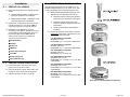
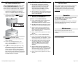
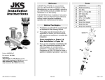
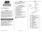
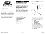
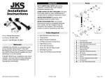
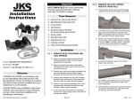
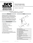
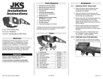
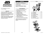
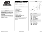
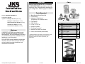
Important Installation Instructions Product: Adjustable BumpStops™ Part Number: PN 1100 Applications: Wrangler JK, 2007+ (front only) Wrangler TJ, 1997-06 (front or rear) Grand Cherokee ZJ, 1993-98 (front only) Cherokee XJ, 1984-01 (front only) Comanche MJ, 1986-92 (front only) Welcome CONGRATULATIONS on purchasing a set of new Adjustable BumpStops™ from JKS Manufacturing. We are committed to providing you with the best products available and your satisfaction is our first priority. Parts MAY BE INSTALLED IN SIX (6) POSSIBLE CONFIGURATIONS depending on individual spacer(s) used. Use appropriate hardware for your configuration. Refer to page 2 for details. Tools Required Metric/Standard Socket Wrench Set Torque Wrench Adjustable Oil Filter Wrench * (for tightening 2.00” BumpStop Spacer) Tape Measure 27/64” Drill Bit 1/2” NC x 13 TPI Tap Anti-Seize Lubricant Coil Spring Compressor * Hydraulic Floor Jack & Jack Stands Factory Service Manual (recommended) * Asterisk denotes tools that are not required for some applications. Thoroughly read instructions first to determine which tools will be required for your application. Pictured with 6 Split Washers – only 2 supplied/needed for installation DESCRIPTION A B C D E F G H 2.00” BumpStop Spacer 1.25” BumpStop Spacer 0.75” BumpStop Spacer 1/2” x 2” Stud 1/2” x 2-1/2” Bolt 1/2” x 1-1/2” Bolt 1/2” x 1-1/4” Bolt Split Washer QTY 2 2 2 2 2 2 2 2 PLEASE READ these Installation Instructions carefully, and save them for future reference, as they contain important installation and maintenance information. 3.25” BumpStop configuration pictured JKS Adjustable BumpStop Installation PN 1100 Page 1 of 3 Installation 1. REMOVE COIL SPRINGS Raise and support the vehicle chassis with jack stands. FRONT INSTALLATION – Position behind front lower suspension arm brackets. REAR INSTALLATION – Position in front of rear lower suspension arm brackets Remove the coil springs per the factory service manual instructions for your vehicle. HINT: A coil spring compressor is useful for removal. Depending on the application, it may be necessary to completely or partially remove any of the following components before spring can be free from upper mount. HINT: Refer to factory service manual for procedures not covered in these instructions. Shock Absorber Swaybar Brake Line ABS Wire Lower Suspension Arm Track Bar Steering Drag Link Spring Retainer Clip 2. PREPARE LOWER SPRING MOUNT Locate the dimple in the center of the lower spring mount on the axle housing. Using the dimple as a guide, drill a 27/64” hole through the center of the lower spring mount. Tap the hole with a 1/2” NC x 13 TPI tap. 3. DETERMINE BUMPSTOP LENGTH JKS Adjustable BumpStops can be installed in six (6) possible configurations (0.75”, 1.25”, 2.00”, 2.75”, 3.25”, or 4.00”), depending on the individual spacer(s) used. Determine the ideal BumpStop length for your application by considering factors such as: Clearance between vehicle tires and body panels during full suspension compression Clearance between axle housing and chassis or drivetrain during full suspension compression Length of existing bump stop extension, if installed Choose the spacer(s) that provides maximum, unobstructed suspension compression for your application from the list below. 0.75” BumpStop Configuration SPACER: 0.75” only HARDWARE: 1/2” x 1-1/4” Bolt + Split Washer 1.25” BumpStop Configuration SPACER: 1.25” only HARDWARE: 1/2” x 1-1/2” Bolt + Split Washer 2.00” BumpStop Configuration SPACER: 2.00” only HARDWARE: 1/2” x 2” Stud only 2.75” BumpStop Configuration SPACERS: 2.00” + 0.75” HARDWARE: 1/2” x 2” Stud + 1/2” x 1-1/4” Bolt + Split Washer 3.25” BumpStop Configuration SPACERS: 2.00” + 1.25” HARDWARE: 1/2” x 2” Stud + 1/2” x 1-1/2” Bolt + Split Washer 4.00” BumpStop Configuration SPACERS: 2.00” + 1.25” + 0.75” HARDWARE: 1/2” x 2” Stud + 1/2” x 2-1/2” Bolt + Split Washer Illustration of 4.00” BumpStop Configuration JKS Adjustable BumpStop Installation PN 1100 Page 2 of 3 4. INSTALL 2.00” BUMPSTOP SPACER ON LOWER SPRING MOUNT FOLLOW THESE STEPS FOR 2.00”, 2.75”, 3.25” or 4.00” CONFIGURATION ONLY. For 0.75” or 1.25” configuration, bypass these steps and proceed directly to section 5: RE-INSTALL COIL SPRINGS. Locate the BumpStop Spacers and hardware required for your application as indicated in section 3: DETERMINE BUMP STOP LENGTH. Thread 1/2” x 2” Stud (D) halfway into hole in center of lower spring mount until one inch of threads remain visible. 5. RE-INSTALL COIL SPRINGS Re-install the coil springs per the factory service manual instructions for your vehicle. DO NOT lower vehicle to ground until all BumpStop Spacers have been installed and properly tightened. HINT: A coil spring compressor is useful for installation. 7. POST-INSTALLATION INSTRUCTIONS Before operating vehicle off-road, test for proper bump stop operation by fully cycling the suspension and checking for obstructions. Add, remove or replace BumpStop Spacers if necessary until maximum unobstructed suspension compression is achieved. Also re-install any of the components that were removed during the REMOVE COIL SPRINGS section of this installation. 6. INSTALL REMAINING BUMPSTOP SPACERS, IF REQUIRED FOR 0.75” or 1.25” CONFIGURATION: Locate the BumpStop spacers and hardware required for your application – refer to DETERMINE BUMP STOP LENGTH section. Slide BumpStop Spacer(s) through coil spring Operation Future BumpStop length adjustments should be made with NO LOAD on the coil springs, and the suspension at FULL DROOP. Depending on the springs used, it may be necessary to spread the coils apart when inserting or removing the 2.00” BumpStop Spacer (A). and position on center of lower spring mount. Apply anti-seize lubricant to appropriate 1/2” Bolt (F or G). Place Split Washer (H) on bolt and insert through spacer(s). Thread bolt into hole in lower spring mount. Using a torque wrench, tighten the 1/2” Bolt to 25 ft-lbs. Maintenance Regular cleaning with pressurized water is recommended to maximize ease of operation and reliability. FOR 2.75”, 3.25”, or 4.00” CONFIGURATION: IMPORTANT: Do NOT thread 1/2” x 2” Stud more than one inch into the 2.00” spacer. Apply anti-seize lubricant to protruding half of 1/2” x 2” Stud (D). Thread 2.00” BumpStop Spacer (A) onto 1/2” x 2” Stud (D). HINT: Recessed end must face up as illustrated above. Tighten the 2.00” BumpStop Spacer (A) using an adjustable oil filter wrench or similar tool. HINT: A rubber strap-type oil filter wrench will prevent damage to the finish when tightening aluminum spacer. Other types of adjustable oil filter wrenches are also effective for gripping the spacer, although it may be necessary to protect the finish with tape or a rag first. JKS Adjustable BumpStop Installation Locate the remaining BumpStop Spacers and hardware required for your application – refer to DETERMINE BUMP STOP LENGTH section. 2010 JKS Manufacturing, Inc & Aftermarketing, LLC Revision Date 5/8/2010 Slide additional BumpStop Spacer(s) through coil spring and position on 2.00” BumpStop Spacer (A). HINT: When stacking spacers, make sure they interlock before inserting hardware. Apply anti-seize lubricant to appropriate 1/2” Bolt (E, F or G). Place Split Washer (H) on bolt and insert through spacer(s). Thread bolt into hole on top of 2.00” BumpStop Spacer (A). Using a torque wrench, tighten the 1/2” Bolt to 25 ft-lbs. PN 1100 Page 3 of 3