1
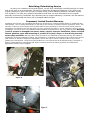
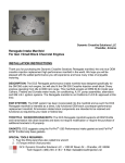
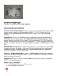
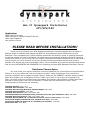
Gen II Dynaspark Distributor
LT1/LT4/L99
Application:
1995-1996 C4 Corvette
1995-1997 Gen 4 Camaro/Firebird/Trans Am
1994-1996 Impala SS
Late 1994-on Caprice
PLEASE READ BEFORE INSTALLATION!!
Thank you for purchasing your Billet Dynaspark Distributor! We have targeted and corrected 10
different areas of weakness that plagues the OEM unit and engineered those refinements into this
distributor. Each completed unit is hand-modified, assembled, and tested in-house to exacting tolerances
so that the product you receive will deliver the performance promised and expected. We have included a
fitment spec sheet for you to verify that your engine component combination tolerances are in order and a
tech tip section for you to follow to correct any possible underlying problems that we have found to
possibly exist without the owners knowledge. Lastly, we’ve included a list of common problems and causes
that we have DOCUMENTED and MEASURED from inspecting countless OEM Optispark Distributor failures.
Distributor Fitment Specs
You must check your engine’s distributor mounting clearances for correct fitment of this distributor.
Failure to do so may affect and void your product warranty if cause of distributor failure was due to
improper installation due to neglect of proper fitment. Please see the CORRECT clearance specs provided
below and compare your combination to them. If ANY one of them is out of spec as compared to our
chart, you must correct the problem before proceeding. Dial calipers make checking of these specs easy.
Removal of timing chain cover may be necessary. If valve train has remained O.E. stock, some
measurements for fitment are not necessary.
Camshaft End Play: .004”-.012”
Camshaft Gear Thickness: .235” MAX.
Camshaft Gear Mounting Bolt Head Installed Height: .200” MAX.
Camshaft Pilot Hole Depth: .360” MIN.
Camshaft Pilot Hole I.D. : MIN. .515”/ MAX .525”
Installed Stacked Pilot Hole Depth Total (as measured w/cam gear installed on cam): .590” MIN.
Camshaft Gear Pilot Hole I.D. : MIN. .515”/ MAX. .540”
Camshaft Mounting Bolt O.D. (as measured from hex corner to hex corner): .560” MAX.
Drive Dowel Height (as measured from camshaft nose face): .605” MAX.
Drive Dowel Height (as measured w/ camshaft gear installed): .375” MAX.
Drive Dowel O.D.: .250” MAX.
Tech Tips
-
-
-
-
-
-
Do NOT remove any of the supplied check valves, filters and orifices that are supplied with vacuum
harness.
Do NOT modify orifice size in any way.
Do NOT add any other additional check valves or orifices to vacuum harness.
Do NOT use the distributor mounting bolts to “pull on” the distributor.
Do NOT over tighten distributor mounting bolts.
Do NOT plum a fuel/nitrous nozzle in front of the Dynaspark vacuum hose that routes to the air
inlet duct before the throttle body. Raw fuel WILL be drawn into the distributor case via the
vacuum hose and the distributor will fail! IMPROPER VACUUM HOSE ROUTING IN THIS
FASHION WILL VOID YOUR WARRANTY!!!!!!!
Apply a small dab of dielectric grease to inside of sparkplug boots.
Check for a leaking fuel pressure regulator by inspecting the vacuum hose connected to it. If it has
fuel in the hose, replace the regulator. Raw fuel from a failing regulator can migrate into the dist.
case (depending on how the distributor vacuum hose is routed) causing it’s early failure and
voiding the warranty.
Burp sparkplug boots after installation. You should hear a slight hiss from the boot when this is
done correctly.
Check coil wire for deterioration at the apex of bends and where it rubs on the water pump and
throttle body area.
Check the water pump for leaks and replace as necessary.
THESE NEXT STEPS ARE CRITICAL FOR DYNASPARK DURABILITY SO FOLLOW CLOSELY!!!
Route the vacuum harness so that it is not kinked in any way and lies comfortably near engine.
The distributor cap vacuum hose that includes the check valves MUST be routed to a manifold
vacuum source for both N/A and forced induction engines. (See figure A)
Check all manifold vacuum nipples at intake manifold for carbon/sludge build-up/plugging and clear
out as necessary.
N/A engines MUST route the distributor case vacuum hose to a port or hole in the air inlet tract
BEFORE the throttle blades- i.e.; air inlet duct that is attached to the throttle body. (See figure B)
Forced induction engines MUST mount the distributor case vacuum hose to a port or hole in the air
inlet tract BEFORE the supercharger or turbo- i.e. air inlet duct to the S/C or turbo. (See figure C)
IF THE DISTRIBUTOR CASE VACUUM HOSE IS ATTACHED TO A MANIFOLD VACUUM
SOURCE, THEN DYNASPARK DISTRIBUTOR DAMAGE WILL OCCUR AND THE WARRANTY
WILL BE VOIDED!!!!!!! THIS HOSE MUST BE CONNECTED TO THE ATMOSPHERIC INLET
DUCT AS DESCRIBED ABOVE!!!!
Do NOT force the distributor into the engine. It should slide in VERY freely and fit square. If it
doesn’t, stop and find out why.
Be sure to install the splined shaft into the timing gear correctly by aligning the small flat keyway
on the distributor drive, with the corresponding flat keyway on the cam gear splines. It is possible
to install this product with the wrong spline being indexed, causing a backfire, starter kickback, or
a no start condition and distributor bearing failure.
Route distributor wiring harness away from any electrical component that may emit high levels of
electro-magnetic interference such as fuel injectors, electric motors, sparkplug wires, ignition
boxes, etc. High RPM misfire may result if these steps are ignored.
Apply a liberal amount of Vaseline to distributor drive shaft before installation to prevent shaft seal
damage from cutting/tearing on assembly.
Apply a small amount of engine oil to distributor drive seal contact surface before installation.
Replace marginal distributor drive seals in timing chain cover before installation.
Do NOT run the engine without a harmonic balancer.
Do NOT use a cam bolt locking plate with the use of this distributor.
6800 MAX engine RPM recommended.
DO NOT, under any circumstances, remove the stainless steel hose clamp that’s placed onto the
Dynaspark distributor cap vacuum hose, as this clamp was purposely put there as a permanent
fixture so the vent hose will not loosen up over time and fall off. Removal of this clamp WILL void
the warranty!!!!!!
Common Causes For Misfire, Premature Drive Bearing Failure, Moisture
Intrusion and Premature Distributor Cap/Rotor Failure
-
Blow dry with air, the area of the sparkplug towers after engine wash down. We have found that
due to the angularity of the plug boot towers downward, water has a tendency to collect near or
around the sparkplug boots causing a misfire.
-
Forward thrust of the distributor assembly from incorrect fitment tolerances WILL cause early
internal distributor drive bearing failure in all instances. Be absolutely sure you follow and measure
ALL clearances and specs provided, before you install this unit.
-
Operating the engine without a suitable harmonic balancer WILL cause the distributor drive
bearing to prematurely fail due to high frequency engine vibrations being transmitted through the
cam drive and into the distributor. Wobbling supercharger pulleys will also decrease Dynaspark
bearing life if the condition exists above. Ignition rotor shattering and/or mounting screw sheering
is also a result of this also.
-
HUGE sparkplug gaps and high energy ignition boxes will shorten the life of the distributor cap and
rotor terminals due the excessive amperage that must pass through the distributor to fire that
plug. Most high output engines do not need such big plug gaps when using a high-energy ignition
system. Typically .035” to .045” is entirely adequate for the engine. Use common sense here.
-
Incorrect routing of the vacuum harness WILL definitely cause moisture intrusion and premature
distributor failure. Follow the instructions closely regardless of what you read elsewhere or what an
aftermarket supercharger or turbo “kit” says to do.
-
We have found that platinum tipped sparkplugs seem to aggravate or induce a misfire when the
platinum pucks come off. This causes the sparkplug gap to increase greatly making it difficult for
the coil to fire the plug at high engine RPM. (see above)
-
Massive RPM clutch dumps sometimes causes rotors to shatter from the load shock the engine
experiences and the “whip-back” condition the timing chain experiences. The looser the timing
chain, the greater chance of rotor shearing. Use common sense here also.
-
This distributor is designed for high performance street use where engines will have an effective
RPM range of 6800 and below. Extreme engine RPM above this level may cause shortened rotor
life. If you elect to operate this product outside of its recommended operating range, you may have
to replace the rotor more often due to fatigue and possibly forfeit the product warranty. It is
advisable that you upgrade to the Gen III rotor-less Dynaspark Distributor that is scheduled to be
released soon. It is designed to be used with the LTCC/individual CNP setup and can withstand
engine RPM up to 8500. Your current Gen I Dynaspark Distributor can then be upgraded with the
high RPM upgrade kit.
-
If a Dynaspark Distributor is not vented properly as per our installation instructions, we
can assure you with 100% certainty that this unit WILL fail prematurely and the
warranty will NOT be honored….period, no exceptions!!! We have spent countless hours
engineering this product for HP use and installing it in ANY other way than what we
outline in these instructions will cause early distributor failure!!!!!!!!!
Installation Instructions and Guidelines
Disassembly:
1) Follow your GM Service Manual instructions for complete removal of the original, OEM Optispark
Distributor for the particular vehicle platform that you have.
2) Discard all OEM vacuum harness hoses, clamps and fittings. Your kit comes complete with a new
vacuum harness.
3) Disconnect the 17” distributor harness from the right side of the intake manifold. It will be a grey,
4-pin connector near the two front fuel injectors.
4) Remove the wire lock located on the bottom side of the gray connector. It should clip onto both
sides of the gray connector. Save this for re-installation
5) Using the steel terminal removal tool supplied with your installation kit, grip the removal tool with
a small pair of pliers to hold it easier.
6) Gently insert the removal tool into the square opening at the terminal’s base as looking into the
connector’s female end. Push slightly on the removal tool until you hear a “pop” and then remove
the tool. This procedure should be very easy, so do not force it or terminal damage will result.
7) You should be able to remove the corresponding wire from the gray connector at this time by
tugging on it from the bottom. If this procedure is done correctly, the wire will come out very
easily.
8) Repeat steps 5-7 for the next three wires.
9) Set the gray connector aside for now. You will re-use it on your new Dynaspark Distributor wiring
harness.
10) Discard the OEM Optispark Distributor harness and distributor drive shaft.
Dynaspark Installation:
1) Clean any oil residue and dirt from the round, large diameter groove located on the timing chain
cover.
2) Replace the distributor drive seal located in the timing chain cover if it shows any sign of leakage.
3) Carefully measure all of the clearances on your engine combination with the correct specs provided
and make sure yours are within those tolerances. If they are not, you MUST correct the condition
before installation of the new Dynaspark Distributor. Failure to do so will void your warranty due to
improper installation and drastically shorten the distributor life.
4) Follow through the Tech Tip section provided and check off each item on the list to prepare the
engine for the new distributor installation. IT IS EXTREMELY CRITICAL THAT YOU FOLLOW
THIS CLOSELY!
5) Take the gray connector that you should have saved from your original Optispark distributor
harness and insert the male terminals from the new distributor. RED=A, BLUE=B, GREEN=C and
WHITE=D. An embossed letter on the connector body labels connector cavities.
6) You should hear a slight snap when they are fully seated. Tug on them slightly to verify correct
seating.
7) Re-install the plastic wire lock onto the gray connector.
8) Locate the keyway in the cam gear. This keyway will be indexed to the keyway on the splined
integral shaft of the Dynaspark.
9) Aligning the keyways together, carefully guide the splined shaft on the Dynaspark into the
corresponding hole located in the camshaft gear until fully seated. The distributor should go on
very easily so do NOT force it on! You may need to tap it with the butt of your hand to fully seat
the distributor. All three distributor case mounting feet should rest evenly on their respective
mounting pads on the timing chain cover. Typically it makes a slight “pop” when fully seated
square.
10) Verify all three mounting locations on the distributor case are evenly flush with the timing cover. If
they are not, remove distributor and find out why.
11) Torque distributor mounting bolts to manufacturer’s specs.
12) Re-connect all vacuum hoses as per the Tech Tip section’s guidelines.
13) Route the new electrical harness as per the Tech Tip section’s guidelines.
14) Re-connect the gray distributor harness connector to the corresponding engine harness connector
on the right side of the intake manifold.
15) Re-install distributor vacuum harness hoses to their respective locations as outlined in the Tech Tip
section provided. You may need to trim the hoses to fit you particular application.
16) Before re-installation of water pump and related engine accessories, test fire the engine to verify
you have everything right BEFORE you put everything back together again for the final time.
Finish Assembly:
1) Follow your GM Service Manual instructions for re-assembly of the remainder of components and
sub-assemblies that were removed to facilitate Optispark Distributor removal.
Rebuilding/Refurbishing Service
As part of our customer service and support, we will offer a distributor rebuilding service for those
that do not wish to do it themselves. The labor to rebuild the Dynaspark Distributor is only $36 to the
original customer for which we will then re-instate a new product warranty based on the same original
time schedule. This offer only applies to distributors that have not been disturbed from the original
assembly performed by Dynaspark. Any rebuilding service request placed by a customer who has had the
distributor disassembled previously will be charged additional labor
Expressed, Limited Product Warranty
Dynaspark will warranty your Dynaspark Distributor for the period of 12 months against defects in components and
workmanship. The 12-month period begins on the date on the returned “Customer warranty agreement” sheet. This
warranty is valid only to the original owner and purchaser of this component to which the serial number has been
identified to the individual. This warranty does not cover unit failure if product is used in automotive racing or vehicle
competition, nor does it cover any installation labor/incidentals reimbursement in any way, shape or form. Warranty
is void if product is damaged from owner abuse, neglect, improper installation, failure to follow
fitment guideline specs and tampering of product in any way, shape, or form during warranty
term by any individual. Warranty claims must be made by the individual of ownership and they are subject to
Dynaspark’s terms and conditions including, but not limited to; verification of component fault or failure do to normal
wear and tear or defective components. Dynaspark reserves the right to refuse a warranty claim if any of these
guidelines are not followed. These terms and conditions are very explicit and will be followed closely. Dynaspark is
proud to stand behind its workmanship and will do so without pause if the above guidelines are followed and
appropriate common sense is applied.
Figure A
Figure B
Figure C