1
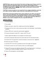
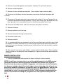
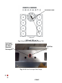
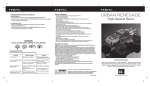
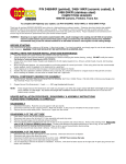
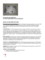
Renegade Intake Manifold
For Gen I Small Block Chevrolet Engines
INSTALLATION INSTRUCTIONS
Thank you for purchasing the Dynamic Crossfire Solutions Renegade manifold, the only true OEM
crossfire injection replacement high performance manifold in the world. We hope you will be
pleased with the added performance you will experience and have many miles of enjoyable
motoring.
DESCRIPTION: The DCS Renegade performance intake manifold was designed specifically for
the GM 350 cubic inch engine, but will also fit the GM 305 Crossfire Injection small-block Chevy
engines operating from idle to 6000 rpm range. This manifold accepts all OEM 82-84 model year
Camaro, Firebird and Corvette water necks, air conditioning, A.I.R. pump assemblies, alternators
and GM H.E.I. ignition systems. The Renegade manifold is not California C.A.R.B. approved at this
time.
EGR SYSTEMS: The EGR system has been incorporated into the manifold and as such the DCS
Renegade manifold is intended as a direct, fully functional OEM stock counterpart performance
replacement manifold. All emission related stock components are intended to be retained and
functional as required by your state or federal law.
THROTTLE / KICKDOWN BRACKETS: The DCS Renegade manifold supports all OEM throttle
and transmission kick down brackets and does not require modification or require the purchase of
additional brackets to fit properly.
GASKETS: DCS suggests using the Fel-Pro© 1205 Performance intake gasket set and Fel-Pro©
60797 throttle body base gaskets.
SPECIAL TOOLS REQUIRED:
1. Fuel line fitting wrenches also called line wrench
2. (1)Torque wrench (foot pounds)
3.
4.
5.
6.
7.
8.
(1) Torque wrench (inch pounds)
Distributor wrench (SAE)
Digital multimeter
Timing light
SAE Allen wrenches – 1/8” & 5/32”
Digital camera (Not required, but could be useful during the installation process)
SUGGESTED ITEMS:
1. Permatex® The Right Stuff®
2. Permatex® Medium Strength Threadlocker Blue Gel™
3. Permatex® Ultra Blue RTV®
SUPPLIED ITEMS BY DCS:
1. 9 – ¼-20 Flathead beveled top plate screws
2. 4 – ¼-20 Button head top plate screws
3. 4 – ¼-20 Threaded studs
4. 5 – ¼-20 Nuts
5. 5 – ¼-20 Washers
6. (2) Fel-Pro© 60797 stock throttle body base gaskets
CAUTION: Proper installation is the responsibility of the purchaser and or installer.
Improper installation will void your warranty and may result in poor performance, engine or
vehicle damage. Dynamic Crossfire Solutions otherwise known as DCS will not be held
responsible for any damages that may result from this installation to your vehicle.
NOTE: PLEASE study these guidelines carefully before attempting this installation. This
removal and installation can be accomplished with common hand tools (with the exception
of torque and fitting/line wrenches) and good mechanic practices. However, you should be
familiar with and be comfortable working on your vehicle. If you do not feel comfortable
performing this removal and installation process, it is highly recommended to have the
installation process completed by a qualified automotive mechanic or a reputable
automotive shop. If you have any questions, please call us at: (480) 23 6 -41 8 4 or e-mail us
[email protected]
RENEGADE MANIFOLD INSTALLATION INSTRUCTIONS
NOTE: The Renegade manifold in made out of 319 aircraft quality aluminum. However, DO
NOT over tighten any bolt or threaded part past its intended torque value or it may cause
the threads to become stripped. DCS is NOT responsible for this type of damage in any way
from improper installation, neglect or misuse.
CAUTION: It is assumed that the installer is familiar with engine maintenance and is
knowledgeable about general automotive safety practices. If unsure what these practices
entail, consult the GM Service Manual for details and precautions associated with engine
maintenance and associated dangers. DCS will NOT be responsible for any personal injury
or any automotive damages in any way associated with improper maintenance practices.
CAUTION: Relieve pressure from the fuel lines before starting removal. Always consult the
GM Service Manual for guidelines. Always use the proper safety equipment before
attempting these procedures. DO NOT use open end or Crescent wrenches on throttle body
fuel fittings, damage may result to the fittings. Always use the proper wrenches when
removing or securing fittings.
CAUTION: If aluminum heads are used, a good anti-seize compound should be considered
on the bolts to prevent damage to your heads when removing the bolts in the future.
NOTE: Before starting the manifold removal, bring cylinder #1 up to TDC on the harmonic
balancer so that the distributor rotor is pointing at plug wire terminal #1 on the HEI cap
when removed and also points to spark plug #1 on head if a line was drawn. See (Figure 3)
In figure 3, the arrow points to the #1 cylinder vs. the spark plug. Consult the GM Service
Manual if unsure how to accomplish this task or any task listed below.
MANIFOLD REMOVAL
1. Disconnect battery.
2. Drain radiator.
3. Remove air cleaner, vacuum lines and disconnect heat tube if applicable.
4. Disconnect fuel lines (inlet, return and crossover tube) at the throttle body’s using fitting/line
wrenches.
5. Remove EGR valve, vacuum lines and solenoid if applicable.
6. Disconnect connectors for both IAC’s, injectors and TPS sensor.
7. Remove power brake booster line on top plate and remove fittings.
8. Disconnect accelerator cable and cruise control cable from TBs and remove brackets.
9. Disconnect all A.I.R. pump hoses, electrical connectors and vacuum lines if applicable.
10. Remove emissions A.I.R. pump.
11. Disconnect PCV valve hose at manifold and remove hose nipple from top plate.
12. Disconnect vacuum hoses on TBs and any others on manifold top plate.
13. Remove TB crossover fuel feed tube in-between TBs using fitting wrenches if installing our
fuel pressure assembly with gauge, otherwise remove as one entire unit.
14. Remove TB mounting bolts and throttle bodies.
15. Remove all manifold top plate mounting bolts, kickdown TV and throttle brackets.
16. Remove manifold top plate.
17. Remove all main manifold mounting bolts. (Cover all ports before removing bolts)
18. Disconnect all distributor electrical connectors and remove distributor hold-down bolt
assembly.
19. Disconnect all the spark plug wires from cap and mark cylinder #1 on cap. Note position of
distributor rotor before removing distributor. You may also tie back your distributor out of the
way if possible versus removing all the wires, whichever way works best for you.
20. Disconnect distributor Power and Tach connectors along with Tach ballast.
21. Remove distributor.
22. Remove radiator hose at housing.
23. Remove thermostat housing and thermostat
23. Disconnect heater hose.
24. Remove manifold.
25. It is recommended that you temporarily seal off any and all passages and holes (your choice
on method) in the block and heads at this time to prevent anything from going into the block or
heads that may cause damage if something were to fall into them until new manifold is readied
for installation.
26. After removal, clean up any and all debris, water or coolant in block valley. Clean all gasket
sealing surfaces on the block and heads thoroughly of all grease and oil before proceeding with
installation.
MANIFOLD INSTALLATION
1. Use only recommended intake gasket set when installing this intake manifold.
NOTE: You will have to create a hole in one of the manifold gaskets for the EGR passage
hole before installation, match the gasket to manifold for port location, see (Figure 4).
Create this hole by any means available. Suggestion, cut a short piece of metal tubing the
size diameter needed and grind the outside edge to form a sharp edge, this will work as a
punch when used with a hammer to cut a perfect hole in the gasket material. You can also
lay the gasket on the stock intake and lightly tap around the EGR hole to see the shape
needed and cut it out. If you do not use the Fel-Pro© 1205 Performance intake gasket you
may not need to make this change in your gasket since some gaskets already have the
hole.
2. Ensure that the cylinder head intake flanges and the engine block end seal surfaces are
thoroughly clean and free from grease and oil. At this time Remove ALL material from the
passages used to block them during the cleaning process.
3. Apply sensor safe sealant such as Permatex® Ultra Blue RTV® or equivalent to both
cylinder head flanges around water ports and attach the intake gaskets. We highly recommend
a sealant from Permatex® called The Right Stuff® for the block end rails also called the “china
rail”. This sealant can be purchased at most auto parts stores. Do Not use this sealant on the
lower manifold flanges or the top plate. This sealant does a very good job at sealing and will
make your manifold extremely hard to remove along with the top plate.
4. Do not use cork or rubber intake end seals if supplied with the gasket set. Use the same
type sealant as in Step 3 above called “The Right Stuff” or equivalent and apply approximately
a ¼” to ⅜” high bead fully across each block end (china rail) sealing surface, overlapping the
intake gasket at each of the four corners sufficiently to form a good seal. This method will
eliminate end seal leakage and give a good tight seal when done properly. We suggest
allowing a minimum of six to eight hours of sealant drying/cure time before starting the engine
after the manifold installation.
5. Carefully, center the manifold above block and lower the manifold straight down onto the
engine block. Ensure the fit is correct especially at front and back before inserting the
mounting bolts. Install the intake manifold with stock 9/16” bolts. Apply a small amount of
thread sealant or Permatex® Medium Strength Threadlocker Blue Gel™ to the threads of all the
mounting bolts (Figure 2). Torque all of the manifold bolts in two steps by the sequence shown
in (Figure 2) to 32 ft/lbs.
6. Install manifold top plate (Figure 1) use the supplied ¼ 20 screws and studs as needed.
Apply a suitable bead of Permatex® Ultra Blue RTV® or any good gasket type sealant around
the flat edge of the lower manifold to form a good gasket. NOTE: If you apply too much
sealant it will ooze out the sides and make a mess. Using the supplied hardware, loosely
insert and start all the screws and studs as needed to obtain the proper fitment. Once the
screws are all installed, starting from the inner screws and working your way outward, torque
screws to 215in/lbs. It is also recommended that you put a small amount of Permatex®
medium strength Threadlocker Blue Gel™ or equivalent thread sealant on each screw thread
to keep them from backing out.
Fig. 1 Manifold Top Plate
Fig. 2 Manifold Bolt Torque Sequence
Distributor Rotor
Fig. 3 Small Block Firing Sequence and at TDC
Cut Gasket
Hole to This
Size Either
Round or
Rectangular
EGR Port
Fig. 4 EGR Port Passenger Side Flange
FRONT
7. Install all other remaining hardware, water thermostat, water neck, distributor, brackets,
vacuum fittings and tubes, tachometer ballast etc… from the stock manifold in the provided
holes in Renegade manifold and top plate. Install the PCV valve hose nipple from the stock
manifold into the plate top provided, raised port in front, see (Figure 1.). Attach supplied hose
to nipple and PCV valve on drivers side valve cover. Install the remaining vacuum fittings from
the stock top plate to the Renegade top plate taking care not to over tighten them.
NOTE: In some situations it may become necessary in some cases to adjust the oil
pressure switch (large black module screwed into the block, rear manifold area) position
slightly towards the rear to accommodate the vacuum tube assembly.
8. Finish the installation in the reverse order on all the remaining parts.
9. It is suggested that the balance of the TBs be checked and then adjust the TPS sensor using
a digital multimeter and set to .525vdc. Adjust the base timing to either the stock setting of 6
degrees BTDC or to whatever value you previously had the timing set to by disconnecting the
EST connector (single connector tan or brown wire connector, this is “NOT” the single wire
connector going to the round silver Tach filter) and using a timing light attached to plug wire #1.
Set the engine idle to GM spec or to whatever value you previously had it set to. Consult the
GM Service Manual for full instructions.
INFORMATIONAL NOTES:
1. Torque manifold 9/16” mount bolts to 32 ft/lbs.
2. Top Plate mount bolts torque to 215 in/lbs. The conversion to foot pounds equals 17.9 ft/lbs
NOTE: Foot pound wrenches are not accurate nor have the resolution at those lower
torque value settings.
3. Small Block Chevy Firing Order: 1-8-4-3-6-5-7-2. Turn Distributor Counter-Clockwise to
Advance Ignition Timing. 6 degree’s BTDC is the Stock Timing setting for a 350 CFI Motor.
4. We recommend that the distributor end play be checked for a range of .004”- .006”. Correct
play is necessary for proper gear contact and timing accuracy. Correct as needed with
distributor shims. Preferably, use a dial indicator to check the run-out, but a feeler gauge is
acceptable to get a gross reading. NOTE: When removing the distributor gear to correct play,
mark the gear and shaft on the bottom (indexing the gear) somehow to ensure that you install
the gear the same position when reassembling or you will not get the distributor rotor to point to
the #1 cylinder when seated.
General Warranty
Dynamic Crossfire Solutions LLC strives to give our customers the highest quality products
possible. DCS warrants each new product to be free from defects in both workmanship and
material for a period of one (1) year from the date of purchase, provided that the product is
properly installed, subjected to normal use and service and that the product is not modified or
changed in any way, nor has been damaged because of negligence by the customer, installer or
used for racing or competition purposes. Customers who believe they have a defective product
should immediately contact DCS and then return it directly to us at Dynamic Crossfire Solutions
LLC at the address supplied below, along with proof of purchase and a complete description of the
problem. The product must be returned freight prepaid. If a thorough inspection of the product by
DCS indicates defects in workmanship or material, our sole obligation shall be to either repair or
replace the product at our discretion. Warranty covers only the product itself and not the cost of
installation or removal.
Disclaimer
The Renegade manifold is a high performance OEM type manifold and may not be street legal in
all 50 states, it is intended for off road use only. As such, DCS is not responsible for any misuse of
this manifold by the customer. The Renegade manifold is not California C.A.R.B. approved at this
time.
Revision: 5/25/10.8
©2010 Dynamic Crossfire Solutions LLC.
DCS | Dynamic Crossfire Solutions LLC. • 1090 W Raven Dr. • Chandler, AZ. 85286
Tech Support: (480) 23 6 -4 18 4 • E-Mail: [email protected]