1
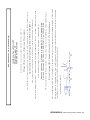
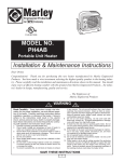
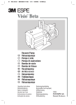
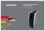
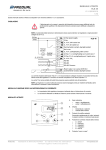
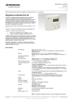
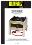
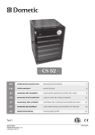
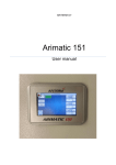
ARITERM
For a su stain able f u tu re
>CHI6AA6I>DCH"dX]
>CHI6AA6I>DCH"dX]
>CHI6AA6I>DCH"dX]
INSTALLATION and
>CHI6AA6I>DCH"dX]
9G>;IH6CK>HC>C<
9G>;IH6CK>HC>C<
9G>;IH6CK>HC>C<
OPERATING MANUAL
9G>;IH6CK>HC>C<
DRAG VÄGGFLÄKT
DRAGVÄGGFLÄKT
VÄGGFLÄKT
DRAG
DRAG
VÄGGFLÄKT
ARROW FLUE CHANNEL
DRAG VÄGGFLÄKT
ARITERM SWEDEN AB
Installation and operating instructions - 2012.08.21v1 - 1/16
ARROW FLUE CHANNEL
Table of contents
1.
Product description.................................................................................................................2
1.1
Components ..............................................................................................................................3
1.2
Technical data ...........................................................................................................................3
2.
Installation .................................................................................................................................4
2.1
Measurements ..........................................................................................................................4
2.2
Access ..........................................................................................................................................5
2.3
Safety against fire ...................................................................................................................5
3.
Electrical connection..............................................................................................................5
4.
Fitting ......................................................................................................................................5-6
Electric diagram .......................................................................................................................7
5.
Adjustment.................................................................................................................................8
6.
Maintenance ..............................................................................................................................8
6.1
Fault .............................................................................................................................................9
6.2
Function and trouble shooting ...........................................................................................9
7.
Warranty .....................................................................................................................................9
1 Product description
The Arrow is a system chimney flue channel with exhaust fan intended to be
installed together with pellets stoves from Ariterm. These stoves are equipped
with a number of safety features that prevents the flue temperature from
reaching dangerous levels. The clean and highly efficient combustion prevents
visible smoke or fumes without having to exit the flue gases above the roof
top.
The function is based on an integrated fan creating a pressure drop in the fan
box on the wall, thus supplying combustion air to the fire bed. The hot flue
gases pass the convection tubes and flue channel trough the wall, and are
being mixed with cool air taken from the outside. This way the mixed flue
gases will be cooled to harmless temperatures before being let out into the
free air.
The precisely controlled combustion of the wood pellets ensures that very
little smoke will be created. When the stove is being started or stopped, some
smoke can be seen and smelled. Normally this will last for a few seconds, but
to ensure that flue gases will not enter the house, the fan box has to be
installed with minimum distances to openable windows and doors etc. as
indicated in section 2.
Declaration of Conformity..................................................................................................10
The Arrow is a system chimney with the following product designation:
T400-P1-D-Vm-15050-G80
T400-N1-D-Vm-L15050-G80
NOTE!
This device must only be connected to a pellet stove of Ariterm brand.
T400
P1
D
Vm-15050
G80
Temperature level
Pressure level
Condensate resistance
Corrosion resistance and flue liner material specification
Soot fire resistance and distance to combustible material
ARITERM SWEDEN AB
Installation and operating instructions - 2012.08.21v1 - 2/16
ARROW FLUE CHANNEL
1.1 Components
Part
1.
2.
3.
4.
5.
6.
7.
8.
9.
10.
11.
12.
13.
14.
15.
16.
17.
18.
19.
20.
21.
22.
23.
Art. nbr
2688
2675
8176
2677
8102
8168
8182
2502
8181
2676
2590
1596
2370
2681
2690
2671
2388
2678
2777
2710
1135
8179
2778
Component
Cover
Fan lid
Screw MRX M4 x 6
Fan housing
Hex nut M4
Screw MC6S M4 x 8
Hex nut M5
Brass bearing
Screw MRX M5 x 8
Wall box
Fan motor
Fan
Insulation 89/30
Air tube Ø80
Wall flange
Seal
Hose Ø40
Flue tube
Flange insulation
Fan wire
Pull down catch
Screw RXS 3,5 x 6,5
Outer wall slab
Fig. 1
ARITERM SWEDEN AB
Installation and operating instructions - 2012.08.21v1 - 3/16
ARROW FLUE CHANNEL
2 Installation
NOTE! Always check with the local authority or an approved inspector before
commencing installation work.
B
2.1 Positioning
D
E
The Arrow system chimney flue channel is CE-marked in accordance with the
Construction Product Regulation, which indicates that it fulfils the regulations for
installation and use, provided the instructions given in this manual is followed.
F
B
J
The house owner must consider The Building Regulations 2000, Combustion
appliances and fuel storage systems. When installed according to the instructions in
this manual, all relevant requirements are fulfilled.
Note that the outlet/terminal has to be positioned with minimum distances
according to the table in Fig. 2.
C
H
H
L
G
A
I
M
H
N
N
M
K
Fig. 2
Legend / Position / min. distance (mm)
A Below air brick, opening window etc. / 300
B Above an opening, air brick, opening window etc: /1000
C Horizontally to an opening, air brick, opening window etc. / 1000
D Below temperature sensitive building components,
e.g. plastic gutters, soil pipes or drain pipes / 75
E Below eaves / 200
F Below balconies or car port roof / 200
G From a vertical drain pipe or soil pipe / 150
H* From an internal or external corner / 300
I Above ground, roof or balcony level / 300
J From a surface facing the terminal / 600
K From a terminal facing a terminal / 1200
L From an opening in a car port (e.g. door, window) into the dwelling / 1200
M Vertically from a terminal on the same wall / 1500
N Horizontally from a terminal on the same wall / 300
* For external corners this restriction can be ignored where the external corner is formed by a building protrusion
less than 450 mm, (for example chimneys on external walls).
ARITERM SWEDEN AB
Installation and operating instructions - 2012.08.21v1 - 4/16
ARROW FLUE CHANNEL
2.2 Access
To ensure safety and facilitate access when sweeping and cleaning, there has to be
ample room in front of the wall box. If the outlet is higher than 2 m, there should be
means of attaching a ladder or working platform. Please consult your local chimney
sweeper.
2.3 Safety against fire
The flue channel’s air tube (14) has to be placed with a minimum 80 mm distance to
combustable building components, e.g. wooden joists.
NOTE!
The chimney sweeper or a local building authorities representative must inspect the
installation before the stove is started.
4.
Repeat with the outer wall. If the outer wall is made of combustible material
the hole is to be made 240 mm diameter. The hole is then covered with the
outer wall slab (23)
5.
Cut the insulation tube (13) and the air tube (14) to length = total wall
thickness including outer wall slab (23), and, if applicable, inner wall slab, and
place it in the wall aperture.
6.
Between the insulation tube and combustible building parts there has to be at
least 40 mm rock-wool. Apply and fasten the outer wall slab (23) with four
screws to the wall.
7.
Fasten the wall box (10) with four screws (supplied) to the wall slab (23) and
pull the electric cable through the insulation tube into the room. Use a
suitable sealing compound to seal off between wall slab and insulation tube.
8.
Push the air tube (14) into the insulation (13) so that the air tube enters over
the spigot of the wall box. It is a tight fit so some pushing force has to be
applied.
9.
Cut the flue tube (18) to length = wall thickness + 180 mm. Place it inside the
air tube (14). Fix the outer end with the pre-drilled Ø4 mm hole to the wall
box using the black M4-screw and corresponding nut. Shut the lid (2), locking
it with the two pull down catches (21) and the locking screw (22). Attach the
cover (1) by pulling the lower ends of the sides outwards and lower the cover
over the wall box. Make sure the tabs enter the corresponding slots.
10.
Slip the fan wire (20) through the hole in the wall flange (15). Push the wall
flange (15) into the air tube (14) and fasten it to the wall with four screws.
Make sure the wall flange is properly centred and in level with the stove flue
outlet. Tighten the screws.
11.
Entering the flue tube (18) into the stove flue outlet, ease the stove in place.
The stove flue outlet must enter the wall flange (15) completely, it’s rubber
seal (16) ensuring a gas tight fit. Attach the black 40 mm hose (17) from the
stove to the wall flange (15), secure it with the black plastic hose clip. Using a
tool, make sure it’s fastened properly.
12.
Attach the fan wire (20) to the connector on the back side of the stove. Red to
red wire, black to black and so on, se electric diagram.
3 Electrical connection
The fan is powered from the stove, using 24 VDC via the attached cable.
4 Fitting
1.
Place the stove on the hearth, close to the wall in the right position. Draw a
line on the wall around the flue outlet of the stove, to mark the position of
the hole for the flue channel.
2.
Remove the stove and drill a pilot hole through the wall. Carefully aim the
drill to get the hole in perfect 90° angle to the wall both vertically and
horizontally.
3.
Using a hole saw, make a 150 - 165 mm diameter hole through the inner wall.
If the inner wall is made of combustible material (e.g. Plywood or or wood
panel) and if local regulations requires soot fire resistance, the hole is to be
made 240 mm diameter. In this case an extra inner wall slab (Ariterm part
number 2779) is to be attached to the wall.
NOTE: If the stove is to be mounted in a corner, use 45° angled flue tube with
Ariterm item number 2727.
ARITERM SWEDEN AB
Installation and operating instructions - 2012.08.21v1 - 5/16
ARROW FLUE CHANNEL
Outer wall slab (23)
Insulation, min 40 mm rock wool
Wall box (10)
Insulation 89/30 (13)
Flange insulation (19)
Wall flange (15)
Seal (16)
Air tube (14)
Flue tube (18)
Fig.3
ARITERM SWEDEN AB
Installation and operating instructions - 2012.08.21v1 - 6/16
Elschema
Electric diagram
RS485
Flamvakt
Digital Temp
Strömtrafo 12VAC 0-12V
Alarm
Generella I/O
Termoelement
VÄGGFLÄKT KMP DRAG
ARROW FLUE CHANNEL
Remote
(tillval)
svart
orange
brun
svart
grå
svart
brun
grå
Fläktlåda
Nätspänning
Blå
Brun
Gul/Grön
svart
röd
Vit
Blå
Brun
Röd
+V (24VDC)
-V (0VDC)
N
L
röd
Nätaggregat
Röd
Svart
Brun
Fig. 4
Grå
6G>I:GBHL:9:C67
ARITERM SWEDEN AB
Installations & Driftsanvisning - 2012.08.08v9 - Sida 7/16
Installation and operating instructions - 2012.08.21v1 - 7/16
ARROW FLUE CHANNEL
6 Maintenance
5 Adjustment
Your new stove with the Arrow flue channel has got basic adjustment, but the
flue values have to be checked when started for the first time. This has to be
done by an authorised installer.
The Arrow has to be periodically cleaned by a chimney sweeper in accordance
with an ordinary chimney. This has to be done at least once per year. Proceed
as follows:
If adjustment is needed, then:
•
Unplug the stove from the electrical outlet.
•
Take of the cover (1) by pulling the lower corners outwards, then lifting
the cover.
•
Remove the fan lid securing screw (22) and open the catches (21).
•
Sweep or vacuum the flue channel all the way to the stove.
•
Remove soot and ash from the fan wheel (12) using a vacuum cleaner or
soft brush.
•
Close and secure the lid and put the cover back.
•
Remove ash that has been pushed into the stove.
•
Unscrew the plug from the front under the hot air inlet aperture (type K6
stoves) or on top of the soot box lid (Lilla Frö). Attach a pressure meter to
the hole.
•
Enter the ”User menu” => ”Service”. Enter the service code.
•
In the Service menu, go to ”Test” => ”Combustion fan”. Adjust the values
with the dial until under pressures below are reached, noting the values.
0 - 10 Pa
”FanVent”
..........
15 - 20 Pa ”FanStart”
..........
45 - 50 Pa ”FanLO”
..........
65 - 70 Pa ”FanHI”
..........
•
Go back to the Service Menu, adjusting all four values as noted above.
•
To obtain the best possible combustion, the values might have to be fine
tuned when the stove is lit and running.
•
Black soot on the stove window is a sign of bad combustion, make sure
the burner cup is clean and properly seated, and increase the fan values.
The fan wheel might need to be cleaned more often, depending on pellet
quality.
In extremely cold conditions, check daily so that ice is not forming in the fan
box.
NOTE!
All pellet combustion generates a grey/brownish ash powder that can settle on
the wall. This is easily washed of using water and a soft brush. If the ash is
black and hard to wash off, the stove needs to be adjusted.
ARITERM SWEDEN AB
Installation and operating instructions - 2012.08.21v1 - 8/16
ARROW FLUE CHANNEL
6.1 Fault
If the stove will not start, check the separate service manual for the stove.
7 Warranty
For warranty issues Ariterm Sweden AB refers to our local Distributor.
6.2 Function and trouble shooting
Before ignition, and continuously when running, the control system in the stove
automatically checks that the Arrow fan is running. If correct function is not indicated, the
stove initiates a cooling process which lasts for 4 minutes. This can not be interrupted.
There will be an error message in the display ”Drgt Err”.
If this happens, the fan has stopped rotating. Check for something that blocks the fan
wheel, or broken electrical connections between the Arrow fan box and the stove.
The alarm can be reset by pushing the dial on the control panel.
ARITERM SWEDEN AB
Installation and operating instructions - 2012.08.21v1 - 9/16
ARITERM SWEDEN AB
Installation and operating instructions - 2012.08.21v1 - 10/16
Kalmar 2012-08-17
The product is intended for use with Ariterm Sweden AB:s pellet stoves only and must be
installed in accordance with the installation manual.
EG-certificate for FPC is issued on the 2012-08-17 with registration number 2392-CPD-1093
Kiwa Sverige AB, Campus Grasvik 1, 371 75 Karlskrona
The systemet for internal Factory Production Control is certified by the notified body
System chimney EN 1856-1-T400-P1-D-Vm-L50150-G80
System chimney EN 1856-1-T400-N1-D-Vm-L50150-G80
Product declaration according to EN 1856-1:2009 section 9:
EN 1856-1:2009 Chimneys - Requirements for metal chimneys - Part 1: System chimney products
The conformity was checked in accordance with the following EN-standard:
Construction Product Regulation CPR EU 305/2011
to which this declaration relates is in conformity with requirements of the following directive:
Drag 09 system chimney flue pipe
declare under our sole responsibility that the product
Ariterm Sweden AB
Flottiljvagen 15
S-39241 KALMAR
Declaration of Conformity
ARROW FLUE CHANNEL
2392
Ariterm Sweden AB, Flottiljvägen 15, S-39241 Kalmar
12
2392-CPD-1093
EN 1856–1:2009
Systemskorsten av metall
T400-P1-D-Vm-L50150-G80
T400-N1-D-Vm-L50150-G80
Compressive strength: NPD
Flow resistance: NPD
Thermal resistance: NPD
Thermal shock resistance: NPD
Flexural strength: NPD
Freeze thaw resistance: Yes
ARITERM SWEDEN AB
Installation and operating instructions - 2012.08.21v1 - 11/16
If these instructions are not followed at installation, operation
and maintenance, Ariterm Sweden AB’s applicable warranties are not binding.
Ariterm reserves the right to make changes to components and specifications
without prior notice.
Ariterm Sweden AB
Flottiljvägen 15, SE-39241 Kalmar
ARITERM SWEDEN AB
www.ariterm.se
Installation and operating instructions - 2012.08.21v1 - 12/16