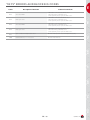
1
prestige
Solo 18 - 32 MkIII
Excellence 18 - 32 MkIII
excellence in hot water
English
Installation,
operating and
servicing
instructions
03/2011 - 664Y4200 • H
EN
Index
FR
Important notes
4
Who should read these instructions
4
Symbols
4
Recommendations
4
Certification
4
Important notes
4
NL
Introduction
5
Technical Characteristics
5
Frost protection
5
User guide
8
Use of the ESYS controller
8
IT
ES
Technical characteristics
9
General characteristics
9
Domestic hot water provision
10
Gas categories
10
Pump performances
11
Boiler pressure drop graph
11
Electrical connection
12
Schematic diagram
12
DE
Heating water recommendations
13
Generality
13
Principle of prevention
13
Installation cleaning
13
14
Prestige Solo 18 - 32 dimensions
14
Prestige Excellence 18 - 32 dimensions
14
Boiler Room
15
Wall mounting
15
Easy kit Prestige Solo 18 - 32 MkIII
16
Easy kit Prestige Excellence 18 - 32 MkIII
16
RU
PL
Installation instructions
664Y4200 • H
EN • 2
EN
Index
Prestige Solo DHW connection + Smart cylinder
19
Prestige Excellence DHW connection
20
Central heating connection
21
Gas connection
21
Installation of a single heating circuit with regulation by ACV 22 room thermostat.
22
Installing a single heating circuit regulated by the Room Unit
24
Installation of high and low temperature heating circuits of 14 kW maximum power with regulation by room-Unit + ZMC-2 of 230 Volts
26
Propane conversion
28
Commissioning and Maintenance
30
Commissioning of the installation
30
Boiler maintenance
30
Resistance of the temperature sensors
30
Front panel removal
31
Disassembling and inspecting the electrode
31
Dismantling the burner
32
Burner thread torque chart
32
Accessory removal
33
Dismantling the exchanger
33
Cleaning the exchanger
33
Code mode
34
Communication mode
35
Parameter mode
36
Test Mode
38
Error Mode
39
Info mode
40
ESYS errors and blocking codes
42
42
RU
List of error codes + solutions
DE
34
PL
ESYS parameters for the specialist
NL
17
ES
Flue connection
FR
17
IT
Installation
EN • 3
664Y4200 • H
FR
EN
Important notes
Who should read these instructions
These instructions should be read by:
- the specifying engineer
- the user
- the installer
- the service engineer
Symbols
The following symbols are used in this manual:
Essential instructions for the correct operation
of the correct installation.
• Before carrying out any work on the boiler, it is important to isolate the
electrical supply.
• The user must not attempt to gain access to the components inside the
boiler or the control panel.
Certification
The apparatus bears the “CE” trademark in accordance with regulations
in force in the different countries [92/42/EEC European “Output” Directive
and the 2009/142/CE “Gas apparatus” Directive]. This appliance also bears the
“HR-TOP” Belgian quality label [gas condensing boiler].
NL
Essential instructions for the safety
of people and the environment.
Important notes
ES
Electrocution hazard: use a qualified technician.
Burn hazard.
If you smell gas:
- Isolate the gas supply immediately.
- Ventilate the room (Open the windows).
- Do not use electrical appliances and do not operate switches.
- Notify your gas supplier and/or your installer immediately.
This manual forms part of the items delivered with the appliance and must
be given to the user to keep in a safe place!
The system must be installed, commissioned, serviced and repaired
by an approved installer, in accordance with current standards in force.
IT
Recommendations
The manufacturer declines all liability for any damage caused as a result
of incorrect installation or in the event of the use of appliances or accessories
that are not specified by the manufacturer.
• Please read this manual carefully before installing and commissioning
the boiler.
The manufacturer reserves the right to change the technical
characteristics and features of its products without
prior notice.
• It is prohibited to modify the interior of the appliance in any way,
without the manufacturer's prior written agreement.
DE
• The boiler must be installed by a qualified engineer, in accordance with
applicable local standards and local codes in force.
The availability of certain models as well as their accessories
may vary according to markets.
• Failure to follow the instructions describing test operations and
procedures could result in personal injury or a risk of environmental
pollution.
• In order to ensure the appliance operates safely and correctly,
it is important to have it serviced by an approved engineer.
PL
• If there is a problem please contact your installer for advice.
• In spite of the strict quality standards that ACV applies to its
appliances during production, inspection and transport, faults may
occur. Please immediately notify your approved contractor of any
faults. Remember to indicate the fault code as it appears on the screen.
• Defective parts can only be replaced with original factory parts.
RU
• Specific regulation in Belgium. The CO2 , gas flow, air flow and air/
gas supply parameters are factory preset and cannot be changed
in Belgium
664Y4200 • H
EN • 4
Jacket
The boiler is enclosed in a steel jacket, which has been treated with
a degreasing and phosphating process, before being stove enamelled
at 220 °C. The inside of this jacket is lined with a layer of thermal and acoustic
insulation, which minimizes losses.
Heat exchanger
The core of the Prestige is a stainless steel heat exchanger which is a result of
exhaustive research and intensive laboratory tests. This reflects almost 90 years
of experience in the use of stainless steel for heating and hot water generation
systems. The specific geometry of the exchanger has been calculated in order
to obtain a very large Reynolds number through all of its routes. The Prestige
thus achieves an exceptional output remaining stable throughout the boiler’s
lifespan, given that it does not produce any oxidation on the exchanger, which
is manufactured entirely of quality stainless steel.
Burner
ACV uses its BG 2000-M burner for the Prestige: this is a modulating air/gas
premix burner providing safe and quiet operation while limiting pollutant
emissions (NOx and CO) to an incredibly low level. Although the ACV BG
2000-M burner is very modern, it uses proven technology and is manufactured
using standard spare parts that are easily available on the market.
Domestic hot water preparation
It is specially designed to operate only as a heating boiler or in combination
with the whole range of ACV water tanks. The Smart Line range is the number
one choice for domestic or commercial applications.
This Prestige MkIII enables you to choose between two sanitary function
methods.
• Full priority mode: (factory preset) the boiler cuts the heating circuit each
time the domestic circuit requires it.
NL
Connection type C63 (x) is prohibited in Belgium.
• Parallel mode: (only with a radiator heating circuit) the boiler functions for
heating and domestic hot water at the same time.
FROST PROTECTION
The boiler is equipped with integrated frost protection: as soon as the outlet
temperature [NTC1 probe] goes below 7 °C, the circulator becomes active.
As soon as the outlet temperature is lower than 3 °C, the burner starts up until
the outlet temperature exceeds 10 °C and the circulator continues to run for
approximately 10 minutes.
If an outdoor temperature probe is connected, the circulator is activated when
the outside temperature drops below the preset threshold.
RU
PL
DE
In order to enable the Prestige boiler to protect the whole system
against freezing, all the valves of the radiators and the convectors should
be completely open.
IT
ES
The Prestige is a wall-hung condensing boiler meeting the requirements of
“HR-Top” standards in force in Belgium. The boiler is certified in compliance
with “EC” standards as a room sealed appliance: C13(x) - C33(x) - C33s C43(x) - C53(x) - C63(x) - C83(x) - C93, but it can also be connected as an
open appliance in category B23 or as a B23P category appliance operating
at positive pressure from the B23P category.
The Prestige Mklll is fitted with a regulator controlled by an “ESYS”
microprocessor, which handles the safety functions (ignition, flame
monitoring, temperature limitation, etc,…) and the boiler’s temperature
control. The ESYS also features a weather dependent regulator. Simply
connect the outdoor temperature sensor, available as an option.
However, this regulator can also operate with a standard (on/off) room
thermostat. The temperature of the system is then dependent on the outside
conditions with compensation for the indoor temperature.
Two rotating buttons placed on the control panel are accessible to the
user, enabling adjustment of the temperature of the heating and domestic
hot water. By entering a specific maintenance code into the unit, qualified
installers may access certain parameters, in order to adapt the boiler to specific
requirements. In principle, these are factory preset for all normal applications.
FR
Temperature control
Technical Characteristics
EN
Introduction
EN • 5
664Y4200 • H
EN
Introduction
Prestige Solo 18 - 32
1. Concentric chimney connection Ø 60/100 mm
with sampling point
1
FR
2. Automatic air vent valve
3. Burner assembly, burner tube, lighting electrode
and flame viewing port
2
6
4. Stainless steel heat exchanger
5. Air inlet tube
3
6. Exhaust tube
NL
7. Fan, gas valve and venturi assembly.
7
4
8. Control panel
9. Removable front cover
10. Condensate collector
11. Hydro-Block outlet with Stepper Motor
5
ES
12. Condensate trap
13. 12 litre heating circuit expansion tank
8
14. Acoustic insulation
15. Circulator with integrated automatic air vent
16. Hydro-Block return with safety valve, pressure
sensor and NTC probe
IT
9
DE
13
14
11
15
12
16
RU
PL
10
664Y4200 • H
EN • 6
EN
Introduction
Prestige Excellence 18 - 32
1. Concentric chimney connection Ø 60/100 mm
with sampling point
1
9
2. Automatic air vent valve
4. Stainless steel heat exchanger
FR
3. Burner unit
2
5. Exhaust tube
6. Condensate collector
3
7. Condensate trap
4
NL
8. Acoustic insulation
10
9. Air inlet tube
10. 12 litre heating circuit expansion tank
11. Control panel
5
12. Hot water cylinder insulation
6
ES
13. 54 litre stainless steel tank for domestic hot water:
14. Stainless steel drywell for domestic sensor:
15. Steel primary cylinder
7
11
16. Hydro-Block return with safety valve, pressure
sensor and NTC probe
17. Hydro-Block flow with Stepper Motor
8
18. Manual bleed valve
18
IT
19. PVCC DHW sparge tube
20. Expansion tank support
21. A circulator with integrated automatic air vent
13
19
DE
12
20
PL
14
15
17
21
EN • 7
664Y4200 • H
RU
16
EN
User guide
Use of ESYS regulator
LCD Display
The LCD display illustrated opposite enables visualisation of all of the
boiler’s functions.
1
7
Heating system
2
The hydraulic circuit pressure is permanently monitored by a pressure sensor.
If the pressure is less than 0.8 bar the display will show “LOP” (Low Pressure)
to indicate to you that filling of the hydraulic circuit is necessary.
3
6
For more information, please ask your installer when the system is delivered.
4
5
The heating system must be kept pressurised [see “commissioning”
chapter – how to determine the operating pressure].
NL
FR
Display structure
The illustration opposite represents all symbols and information that the
display can show during its function.
1. Numerical field displaying the temperatures
In the case of repeated fills, contact your installer.
2. Temperature symbol
3. Symbol to select heating mode
4. Symbol indicating that the burner is operating
5. Symbol indicating that the circulator is operating
6. Symbol to select domestic hot water mode
ES
7. Bar symbol
ON/OFF switch
Fault:
The temperature setting of the appliance and the safety functions of the
boiler’s various parts are constantly monitored by the “ESYS” system. If a fault
occurs, the ESYS turns the unit off and displays an error code: the screen flashes
and the first character is an “E” followed by the fault code.[see list of faults]
IT
To reset the unit:
-Execute the “RESET” function by turning the domestic setting button
to the left up to minimum, then continue to turn the button lightly and
repeatedly for 3 seconds.
- If the fault code appears again, contact your installer.
PL
DE
Setting the temperatures
A
B
A. Setting the heating temperature and summer/winter function:
Range adjustable from 20 °C to 90 °C:
When the thermostat is positioned on , the heating circuit is
deactivated and the boiler is then in summer mode.
RU
B. Adjustment of domestic hot water temperature and RESET function:
Setting range is from 20 °C to 80 °C:
To operate the “RESET” function, turn the domestic hot water
adjustment button to the left up to minimum, then continue to turn the
button lightly and repeatedly for 3 seconds.
664Y4200 • H
EN • 8
EN
Technical char acteristics
General characteristics
Natural Gas
18
Central heating
32
Prestige Excellence
Propane
18
Natural Gas
32
18
32
Propane
18
32
Max heat flow [Input] - PCI (low calorific value)
kW
18,0
31,0
18,0
31,0
18,0
31,0
18,0
31,0
Max heat flow [Input] - PCS (high calorific value)
KW
19,9
34,4
19,5
34,8
19,9
34,4
19,5
34,8
Min. heat flow [Input]
kW
2,2
3,8
3
5,2
2,2
3,8
3
5,2
Max. useful power 80/60 °C
kW
17,5
30
17,5
30
17,5
30
17,5
30
Min. useful power 80/60 °C
kW
2,1
3,7
2,9
5,1
2,1
3,7
2,9
5,1
Max. useful power 50/30 °C
kW
19,1
32,6
19,1
32,6
19,1
32,6
19,1
32,6
%
97
96,8
97
96,8
97
96,8
97
96,8
Efficiency at 100% load 50/30 °C
%
106,1
105
106,1
105
106,1
105
106,1
105
Efficiency at 30% load [EN677]
%
108
107,3
108
107,3
108
107,3
108
107,3
Flue gases
CO emissions [max power]
mg/kWh
10
65
3
109
10
65
3
109
NOx emissions [EN483]
mg/kWh
39,9
39,9
51
68
39,9
39,9
51
68
5
5
5
5
5
5
5
5
NOx class [EN483]
Flue gas temperature - Max output power 80/60 °C
Mass flow rate of combustion products
°C
kg/h
62
83
62
83
62
83
62
83
29,56
51,76
29,05
50,89
29,56
51,76
29,05
50,89
Maximum pressure loss for the flue
Pa
130
130
130
130
130
130
130
130
Maximum length of concentric flue pipe
Ø 60/100 mm
m
25
12
25
12
25
12
25
12
Gas flow rate G20 - 20 mbar
m3/h
1,9
3,28
1,9
3,28
Gas flow rate G25 - 25 mbar
3
2,21
3,81
2,21
3,81
0,74
1,27
ES
NL
Efficiency at 100% load 80/60 °C
FR
Prestige Solo
Gas flow rate G31 - 37 mbar
m /h
m3/h
g/sec.
0,74
1,27
0,39
0,67
0,39
0,67
CO2 [max output power] (with front panel closed)
% CO2
8,9
8,9
10,5
10,5
8,9
8,9
10,5
10,5
CO2 [max output power] (with front panel open)
% CO2
8,7
8,7
10,3
10,3
8,7
8,7
10,3
10,3
CO2 [min output power] (with front panel closed)
% CO2
8,6
8,6
10,2
10,2
8,6
8,6
10,2
10,2
Ø
3/4"
3/4"
3/4"
3/4"
3/4"
3/4"
3/4"
3/4"
°C
90
90
90
90
90
90
90
90
L
8
8
8
8
16
16
16
16
54
54
54
54
bar
3
3
3
3
3
3
3
3
mbar
85
260
85
260
85
260
85
260
Ø
3/4"
3/4"
3/4"
3/4"
3/4"
3/4"
3/4"
3/4"
L/h
740
1300
740
1300
740
1300
740
1300
X4D
X4D
X4D
X4D
Gas connection (male)
IT
Gas
Capacity of the domestic circuit
Max operating pressure of the heating circuit
Heat exchanger pressure drop [∆T = 20 °C]
Heating connection (male)
Nominal flow
L
PL
Maximum operating temperature
Heating circuit capacity
Electrical connection
Class
Supply voltage
DE
Hydraulic parameters
IP
V/Hz
230 / 50 230 / 50
X4D
X4D
230 / 50
230 / 50
230 / 50 230 / 50
X4D
X4D
230 / 50
230 / 50
W
135
150
135
150
135
150
135
150
Drained weight
kg
46
46
46
46
78
78
78
78
RU
Maximum absorbed electrical power
EN • 9
664Y4200 • H
EN
Technical char acteristics
Domestic hot water provision
Prestige Excellence
FR
System operating at 80 °C
18
32
Peak flow rate at 40°C [∆T = 30 °C]
L/10'
175
224
Peak flow rate at 40 °C [∆T = 30 °C]
L/60'
583
835
L/hour
490
745
Peak flow rate at 60 °C [∆T = 50 °C]
L/10'
102
103
Peak flow rate at 60 °C [∆T = 50 °C]
L/60'
348
353
L/hour
295
320
Minutes
28
25
Continuous flow rate at 40°C [∆T = 30 °C]
Continuous flow rate at 60 °C [∆T = 50 °C]
NL
Reheat time for domestic hot water
Gas categories
ES
I2E(S)
I3P
II2H3B/P
II2H3P
II2E3B/P
II2E3P
II2Er3P
II2L3B/P
II2L3P
II2ELL3B/P
II2S3B/P
G20 (mbar)
20
20
20
20
20
20
20
20
20
20
G25 (mbar)
25
25
25
25
25
25
25
25
25
25
G30 (mbar)
37
30
50
37
50
30
50
30
37
50
30
37
30
50
G31 (mbar)
37
30
50
37
50
30
50
30
37
50
30
37
30
50
AT
Austria
BE
Belgium
IT
CH Switzerland
CY Cyprus
CZ Czech Republic
DE Germany
DE
DK Denmark
EE
Estonia
ES
Spain
FR
France
GB Great Britain
GR Greece
HR Croatia
HU Hungary
IE
Ireland
IT
Italy
LT
Lithuania
PL
LU Luxembourg
NL Netherlands
NO Norway
PL
Poland
PT
Portugal
RU
RO Romania
SE
Sweden
SI
Slovenia
SK
Slovakia
TR
Turkey
664Y4200 • H
EN • 10
EN
Technical char acteristics
Pump performances
6
6
5
5
4
4
2
C
C
2
B
B
1
3
1
A
A
0
0
200
400
600
NL
3
FR
6 meter head: Prestige 32
Pressure (mH2O)
Pressure (mH2O)
4 meter head: Prestige 18
800
1000
1200
0
1400
200
0
400
800
1000
1200
1400
30
35
Flow (litres / hour)
ES
Flow (litres / hour)
600
IT
A = Available pressure (for the heating circuit) circulator on 1
B = Available pressure (for the heating circuit) circulator on 2
C = Available pressure (for the heating circuit) circulator on 3
Boiler pressure drop graph
6
3
5
2,5
3
2
1,5
1
0
200
400
600
800
1000
1200
1400
Flow (litres / hour)
0
0
5
10
15
20
25
Domestic water quantity (litres / minute)
EN • 11
664Y4200 • H
RU
0,5
1
0
2
PL
4
DE
Domestic hot water:
Prestige excellence 18 - 32
Pressure drop (mH2O)
Pressure drop (mH2O)
Heating:
Prestige Solo 18 - 32
Prestige Excellence 18 - 32
W
W
R
R
Bk
W
R
1. 230 V ~ 50 Hz feed outlet
2. On/Off switch
3. Burner feed
4.Circulator
5. Gas valve rectifier
6. Pressure sensor
7. NTC2 return sensor
8. NTC1 flow sensor
9. Connection terminal
10. Clip-in connector (option)
11. NTC5 flue-gas temperature sensor
12. Burner PWM plug
13.Stepper
14. ESYS programming sheet
15.“ESYS”
15
1
1 2
2
3
4
6
5
NTC 4
7
8
9
8
4
5
6
7
4
1
5
2
6
3
X2
10 11 12 13 14
3
1 2 3 4 5 6
2
1
1
2
5
3
4
1 2 3 4 5
5
X13
1 2 3 4 5 6 7 8 9 10 11 12 13 14
Br
Bk
1 2
Gr
Gr
1 2 3
Br
R
NTC 3
R
R
1
8
R
Gr
W
BUS A
W
1
7
9
Bk
BUS B
Bk
Bk
3
10
Bk
2
B
C
13
12
D
B C A D
A
11
3
1
4
2
9
4
X12
1 2 3 4
Bk
1
R
2
3
4
2
14
3
6
1 2 3 4 5 6
1
4
1 2 3 4
1
7
2
3
6
4
9
2
5
3
8
10
5
X1
X15
1 2 3 4 5 6 7 8 9 10
6
1
4
1
1 2 3 4 5 6
2
3
1 2 3
1
W
Y / Gr
3 2 1
Br
3
Br
W
Br
Y
2
6
1
5
7
3
8
4
X14
1 2 3 4 5 6 7 8
1 2
1
11
NTC 5
Y
10
Y
Not used
Bk
R
2
4
3
8
7
1
3
2
10
5
4
5
ON / OFF
B
2
B
F00
X11
3
Br
X0
9
4
2
1 2 3 4 5
1
Br
1 2 3 4
6
1
1 2 3 4 5 6 7 8 9 10
V
Safety
thermostat
w
W
W
W
B
W
G
Y / Gr
W
B
Br
R
W
Y / Gr
Gr
B
W
Br
Or
Bk
W
B
W
NTC 1
B
R
NTC 2
V
6
Y
B
NL
B
ES
Br
Bk
Br
Br
V
V
W
IT
Bk
DE
12
FR
1
230 V ~ 50 Hz
Y / Gr
Y / Gr
B.Blue
Bk.Black
Br.Brown
Gr.Green
Or.Orange
R. Red
Violet
V. White
W. Y.Yellow
Y/Gr.Yellow/Green
Y / Gr
Y / Gr
PL
Y / Gr
EN • 12
Y / Gr
664Y4200 • H
Y / Gr
RU
EN
ELECTRICAL CONNECTION
GENERALITY
Filling water contains elements susceptible to damage boilers heat exchangers
in case their concentration goes out of an adequate range.
The risk is growing with the size of the installation since the water content per
installed kW increases.
Those parameters has to be measured and water needs chemical treatment
in case of values out of range. ACV recommends the additives from Fernox
(www.fernox.com) and from Sentinel (www.sentinel-solutions.net).
Note that these products must be used in strictly accordance with the water
treatment manufacturer’s instructions.
EN
HEATING WATER RECOMMeNDATIONS
In case at least one of those recommendations can
not be warranted, the boiler must be hydraulically
separated of installation using plate heat exchanger
NL
OXYGEN
Depending of the volume of the installation, a certain amount of oxygen is
introduced in the installation. During the exploitation of the installation, some
oxygen can be brought in the system in case of water re-filling and/or presence
of hydraulic components without oxygen barrier (PE tubes & connectors).
The oxygen reacts with the steel creating corrosion and generating sludges.
While the ACV Prestige heat exchanger is made of stainless steel and is by
consequent not sensible to corrosion, the sludges generated in carbon steel
part of the installation (radiators, …) will lay down in the hot parts including
the heat exchanger.
The sludges in the heat exchanger have the effect to reduce the water flow rate
and to thermically insulate the active parts of the heat exchanger, what could
lead to damages.
Before filling an installation, it must be cleaned following the standard
EN14868.
Chemical cleaners can be used, ACV recommends the additives from Fernox
(www.fernox.com) and from Sentinel (www.sentinel-solutions.net).
Note that these products must be used in strictly accordance with the water
treatment manufacturer’s instructions.
FR
INSTALLATION CLEANING
PRINCIPLE OF PREVENTION
How to prevent against oxygen ?
ES
- mechanical system : an air remover combined to a sludges remover installed
following the constructors specifications limits efficiently the risk of oxygen
in the installation;
- chemical system : additives allow the oxygen to stay in solution in the water.
ACV recommends the additives from Fernox (www.fernox.com) and from
Sentinel (www.sentinel-solutions.net).
note that these products must be used in strictly accordance with the water
treatment manufacturer’s instructions.
HARDNESS
Depending of the volume of the installation, the hardness of water and the
possible re-filling, a certain amount of lime is introduced in the installation.
The lime will lay down in the hot parts, including the heat exchanger creating a
reduction of the water flow rate and a thermal insulation of the active parts of
the heat exchanger. That phenomena can damage the heat exchanger.
IT
Acceptable hardness range:
mmolCa(HCO3)2 / l
°DH
°FH
0,5 - 1
2,5 - 5,6
5 - 10
How to prevent ?
DE
the filling and re-filling water must be softened if necessary to match the
working range. Additives can be used to keep the calc in solution in the water,
ACV recommends the additives from Fernox (www.fernox.com) and from
Sentinel (www.sentinel-solutions.net).
note that these products must be used in strictly accordance with the water
treatment manufacturer’s instructions.
The water hardness must be check regularly and recorded in a file.
OTHER PARAMETERS
6,6 < pH < 8,5
Conductivity
< 400 μS/cm (a 25°C)
Chloride
< 125 mg/l
Iron
< 0,5 mg/l
Cu
< 0,1 mg/l
RU
Acidity
PL
In addition to the oxygen and the hardness, some other parameters must be
controlled in the water of heating installations.
EN • 13
664Y4200 • H
EN
Installation instructions
PRESTIGE Solo 18 - 32 dimensions
340
NL
878
965
FR
130
A Heating outlet Ø 3/4" [M]
A
78
400
B
C
D
E
68
B Primary flow to DHW Ø 3/4" [M]
133
C Primary return to DHW Ø 3/4" [M]
263
D Heating return Ø 3/4" [M]
ES
328
E Gas connection Ø 3/4" [M]
445
500
250
260
PL
1000
1085
DE
IT
PRESTIGE Excellence 18 - 32 dimensions
A
F
BC
D
E
75
117,5
229
178
A Heating outlet Ø 3/4" [M]
210
B Gas connection Ø 3/4" [M]
333
C Heating return Ø 3/4" [M]
533
630
RU
560
D Cold water inlet connection Ø 3/4" [M]
E DHW outlet connection Ø 3/4" [M]
F Gas connection Ø 3/4" [M]
664Y4200 • H
EN • 14
EN
Installation instructions
Installation area
FR
- Make sure that all air vents are unobstructed at all times.
- Do not store any flammable products in the boiler room.
- Do not store any corrosive materials, paint, solvents, salts, chlorine products
or any other detergent products in the vicinity of this appliance.
- If you smell gas, do not operate electrical switches, close the gas valve on
the meter, ventilate the rooms and contact your installer.
- The area around the boiler must be clean and free from dust.
In case of works (boiler area or near the external air inlet)
please switch off the boiler, so as to avoid the accumulation of
dust in the combustion system.
Accessibility
Min. 25 mm
DE
Min. 220 mm
IT
ES
Min. 25 mm
Min. 300 mm
NL
The appliance must be placed in such a way that it is always easily accessible.
Furthermore, the unit must have the following minimum clearance around it.
Wall mounting
PL
- The boiler must be mounted on a non-flammable wall.
- Drill two holes with a depth of 75 mm using a 10 mm drill bit, following the
spacing given below.
- Fasten the wall mount using the supplied anchor screws.
- Attach the boiler to the wall mount.
53,2 mm
48,4 mm
101,6 mm
RU
101,6 mm
48,4 mm
53,2 mm
EN • 15
664Y4200 • H
Easy kit Prestige Solo 18 - 32 MkIII
(10800184)
Easy kit Prestige Excellence 18 - 32 MkIII
(10800185)
1100 mm
875 mm
RU
PL
DE
IT
ES
NL
FR
EN
Installation instructions
78 mm
664Y4200 • H
35 mm
EN • 16
Flue connection
Example of calculation
Prestige 32 with concentric
chimney duct:
- The connections must comply with the NBN D51-003 standard taking into
account local energy suppliers’ instructions, fire regulations and regulations
relating to “pollution”.
EN
installation
1000 mm
The resistance of this system is as follows:
(2 x 10) + (2 x 9) + (3 x 9) + 35 = 100 Pa.
As this value is lower than the maximum
authorised resistance, this installation is
therefore compliant.
2000 mm
- There must be no obstructions or inlets to other appliances within a radius
of 0.5 metres around the Prestige terminal.
- The maximum pressure drop of the chimney is 130 Pascal. You can
calculate this value using the following table: (please see sample calculation).
2000 mm
IT
ES
-The C33s and C93 configuration enables airtight operation in a preexisting chimney. The combustion air crosses the space between the
tubing and the pre-existing chimney. Make sure to clean the pre-existing
chimney thoroughly prior to installation, especially if there is soot or tar
residue. Make sure that there is a clearance area for the combustion air at
least equivalent to the area that would have been provided by separate
concentric ducts or air intake ducts.
NL
- The horizontal flue gas exhaust ducts must be installed with a sufficient
degree of slope towards the boiler: 3° of slope = 5 mm per metre of duct.
FR
The diagram below consists of the following
parts: 2 90° pipe bends + 2 metres of horizontal
pipe + 3 metres of vertical pipe + one vertical
terminal.
- Owing to its built-in gas/air ratio regulator, the Prestige is, to a large extent,
independent of pressure drops in the air intake and flue-gas exhaust
systems. However, the maximum pressure drop of this system may not be
exceeded; otherwise, the output would diminish. Nevertheless, the gas/
air ratio regulator always guarantees optimal combustion with very low
emissions.
Flue pressure drop chart in Pascal (1 Pascal = 0.01 mbar)
Separate air inlet
Ø 80 mm
Separate exhaust
Ø 80 mm
18
32
18
32
18
32
Straight pipe 1 m
3
9
0.5
15
0.7
2.0
90° bend
4
10
0.6
1.9
1.1
3.4
45° bend
3
7
0.4
1.3
0.8
2.3
Vertical terminal
12
35
Horizontal terminal
9
26
PL
Concentric chimney duct
Ø 60/100 mm
DE
Prestige Solo / Excellence 18 - 32
RU
This table is based on ACV equipment and cannot be applied generally.
EN • 17
664Y4200 • H
EN
installation
B23P
C43
B23
C43
C33
C53
IT
ES
NL
FR
Chimney connection options
C13
DE
C93
B23 :Connection to an exhaust duct venting the combustion products
outside of the installation area, with the combustion air being drawn
directly from this area.
PL
B23P:Connection to an exhaust system of the combustion products
designed to operate with positive pressure.
C13 :Connection by pipes with horizontal terminals that simultaneously
take in combustion air for the burner and discharge combustion
products outside through openings that are either concentric or close
enough together to be subjected to similar wind conditions.
C33 :Connection by pipes with vertical terminals that simultaneously take
in fresh air for the burner and discharge the combustion products
outside through openings that are either concentric or close enough
together to be subjected to similar wind conditions.
C93 :Connection with an individual system of which the exhaust duct for
the combustion products is installed in an exhaust pipe that is part of
the building. The appliance, the exhaust duct and the terminal units
are certified as an inextricable assembly.
C43 :Connection by two ducts to a collective duct system serving more
than one appliance; this system of collective ducts features two
ducts connected to a terminal unit that simultaneously intakes fresh
combustion air and discharges the combustion products outside
through openings that are either concentric or close enough together
to be subjected to similar wind conditions.
C53 :Connection to separate ducts for the supply of combustion air and for
venting the combustion products; these ducts may end in zones with
different pressure levels.
RU
C63 :Type C boiler which is intended for connection to a room sealed flue
system which is approved and sold separately.
(Prohibited in Belgium).
664Y4200 • H
EN • 18
Prestige Solo + Smart cylinder
DHW connection
EN
installation
Prestige Solo
Optional equipment
Code
5
Description
1
Sensor NTC 12 kΩ:
Monitors the external domestic hot water tank
5476G003
2
4
3
7
FR
- Flush the system before connecting the DHW equipment.
- It is essential that the DHW cylinder is filled and pressurised before filling
the central heating circuit.
6
NL
8
Before carrying out any work on the boiler, it is important
to isolate the electrical supply to the unit.
1. The NTC 12k Ω sensor must be placed in the drywell of the cylinder and
connected to the boiler connection terminals 3 and 4 [see diagram below].
4
5
6
7
8
IT
W
9
10
11
12
DE
3
BUS B
2
Domestic cold water isolation valve
Non-return valve
Safety valve
Pressure reducer
DHW expansion vessel
DHW temperature control valve
Hot water tap
Condensate recovery trap
Adjustment of domestic
hot water production
temperature.
BUS A
1
1.
2.
3.
4.
5.
6.
7.
8.
ES
2. Before starting up the boiler, an “Auto Set” is necessary so that the DHW
sensor is detected.
To do this, turn the right button to “RESET” then start the boiler up by
pressing on the ON/OFF switch.
From the moment that the display shows “SET” the “RESET” button can
be released.
Activate the “Auto Set” function so that the boiler detects the
sensor or the thermostat.
PL
It is possible to use the domestic hot water cylinder
thermostat, in place of the NTC 12kΩ sensor.
Factory
10
0
EN • 19
Description
T plus = temperature increase of
primary flow during domestic hot
water mode
0 = domestic hot water priority mode
1 = in parallel
664Y4200 • H
RU
EN
installation
Prestige Excellence DHW connection
Adjustment of domestic
hot water production
temperature.
The Prestige Excellence can be connected directly to the DHW circuit.
Flush the system before connecting the DHW.
FR
The system must be equipped with an approved safety unit including a 7 bar
safety valve, a non-return valve and an isolation valve. (Temperature and
pressure relief valve required in the UK).
When the operating pressure exceeds 6 bar a pressure reducer must be
installed before the safety unit.
During the heating process, the domestic water expands and the pressure
increases. As soon as the pressure exceeds the safety valve setting, the valve
opens and discharges. The use of a DHW expansion tank (minimum 2 litres)
will avoid a discharge of water and reduce water hammer.
NL
Vent the cylinder by opening a hot water tap. Warning: the simultaneous
evacuation of water and air may cause spluttering.
The hot water can reach temperatures greater than
60°C. This can lead to risk of burns.
Therefore, the installation of a temperature control
valve on the hot flow immediately after the appliance
is advised.
Factory
10
ES
0
The use of stop taps on the DHW system can cause pressure
waves on closing. To avoid this use devices to alleviate
water hammer.
DE
IT
Prestige Excellence
RU
PL
1
2
4
7
3
6
5
1.
2.
3.
4.
5.
6.
7.
Domestic cold water isolation valve
Non-return valve
Safety valve
Pressure reducer
DHW expansion vessel
DHW temperature control valve
Hot water tap
664Y4200 • H
EN • 20
Description
T plus = temperature increase of
primary flow during domestic hot
water mode
0 = domestic hot water priority mode
1 = in parallel
Central heating connections
- Fill the system with fresh tap water. Contact your ACV representative
or installer about the use of inhibitors.
- It is possible that the connections are capped due to the presence of
residual water from tests carried out on the appliance. Please ensure
that all the caps are removed before filling the appliance.
- The sluice gate connections for filling and/or draining of the appliance are
found on the bottom.
- Fill the appliance to a minimum pressure of 1.0 Bar.
- Vent the complete system and refill the system to 1.5 Bar.
- The heating circuit must be designed so as to ensure a continuous
flow around the boiler; if this flow can be interrupted when all the
thermostatic valves are closed then a bypass is required to assure
a minimum flow of 200 l/h.
- Ensure that the condensate trap is fitted and connect the hose to the
drain using a connection that can be inspected. If necessary fill the trap
with clean water. Take the necessary precautions to prevent any risk of the
condensate freezing.
ES
NL
Recommendations
- The whole central heating system must be thoroughly flushed with clean
water before being connected to the appliance.
- Mount the boiler using the supplied bracket ensuring that it is level or
alternatively use the assembly panel available as an option for the Prestige
Solo model.
- If the boiler is mounted on a wall of lightweight construction it is advisable
to use rubber dampers to reduce the transmission and amplification
of noise.
- The optional mounting plate for the Prestige Solo is equipped with fittings
to provide rapid assembly and connection to the central heating and DHW
systems. If you do not use the assembly panel, the connections can be
carried out using standard straight adaptors.
- The central heating safety valve is integrated and located under the appliance.
It must be connected to the drain with an air gap (allowing an inspection).
- The central heating pump is incorporated into the appliance and, via
the three position switch; its speed can be adapted according to the
system requirements.
-The Prestige Solo is equipped with a 12 litre integrated expansion tank.
Depending on country and associated standards, the Prestige Excellence is
equipped with a 12 litre expansion tank.
This is sufficient for systems containing approximately 120 litres of water for
central heating. For systems of a larger capacity, an adapted expansion tank
can be added to the Prestige Solo and to the Prestige Excellence.
Heating connection:
overview
IT
Isolating valve in the heating circuit
Safety valve calibrated to 3 bar, with pressure gauge
Non-return valve
System filling unit
External expansion tank (if necessary)
Drain down valve
Condensate trap connection
2
7
1
It is compulsory to install a safety thermostat
on the low temperature heating circuit outlet.
DE
1.
2.
3.
4.
5.
6.
7.
FR
EN
installation
3
1
4
5
PL
6
Gas connection
- Vent the gas pipe and carefully check that there are no leaks on the
boiler’s internal and external pipes.
- The gas connections must comply with all applicable standards
(in Belgium: NBN D51-003).
- Check the system’s gas pressure. Please refer to the technical
data chart.
- If there is a risk of dirt from the gas network, place a gas filter upstream
of the connection.
- Check the gas pressure and consumption when commissioning
the appliance.
EN • 21
RU
- Our Prestige® boilers are equipped with a Ø 3/4”M connection
to connect a gas isolator.
664Y4200 • H
EN
installation
Installation of a single heating
circuit regulated by an ACV 22 room
thermostat
AF120
Schematic diagram
ACV 22
FR
The heating system (radiators or floor) is controlled by an On/Off
room thermostat.
In this configuration, the boiler constantly adapts its operation to the outdoor
temperature, if an outside temperature sensor is connected.
The circulator is triggered as soon as the room thermostat generates
a heat demand.
NL
Advantages for the user:
- Comfort
- Maximum output
- Simplicity of the system
ES
A
B
Before the boiler’s start up, an “Auto Set” is necessary so that the boiler
detects the DHW sensor.
To do this, turn the right button to “RESET” then start up the boiler by
pressing on the ON/OFF switch.
From the time that the display shows “SET” the “RESET” button can
be released.
A. - Heating temperature setting guidelines without external sensor
- Maximum heating temperature limit with external sensor
- The thermostat is positioned on , the heating circuit is deactivated
and the boiler is then in summer mode..
IT
B. - Domestic hot water temperature setting.
(Prestige Excellence or as an option with an external domestic hot
water tank).
Optional equipment
Description
10800018
ACV 22 Room thermostat
10510100
Outside temperature sensor, 12 kΩ — AF120
10510900
Safety thermostat RAM 5109:
Compulsory to protect all floor heating circuits.
5476G003
Sensor NTC 12 kΩ:
Monitors the external domestic hot water tank.
RU
PL
DE
Code
664Y4200 • H
EN • 22
4
5
6
8
FR
7
9
10
11
12
NL
3
W
ES
It is compulsory to install a safety thermostat
on the low temperature heating circuit outlet.
Heating curve
Description
P1 = 10
90
P1 = 9 P1 = 8
P1 = 7
P1 = 6
80
10
0
T plus = temperature increase of
primary flow during domestic hot
water mode
0 = domestic hot water priority mode
1 = in parallel
P1 = 4
60
P1 = 3
50
P1 = 2
40
P1 = 1
30
DE
20
Minimum temperature of the
heating outlet
P1 = 5
70
P2 = 20
10
20
15
10
5
0
-5
-10
-15
-20
-25
External temperature (°C)
PL
Selection of the heating curve
RU
6
IT
Factory
Water temperature (°C)
2
BUS B
1
Only for low
temperature
heating circuits
BUS A
Only with a domestic
hot water tank.
EN
installation
EN • 23
664Y4200 • H
EN
installation
Installing a single heating circuit
with Room Unit regulation
Schematic diagram
AF120
Room Unit
In this configuration, the boiler continuously adapts its operation to the
outside temperature.
NL
FR
A Room Unit thermostat controls the heating (radiators or floor heating).
The latter enables a choice between different heating functions and authorises
up to 3 daily programmes for heating and for domestic hot water. The Room
Unit thermostat has the advantage of displaying information on system status.
ES
A
B
Before the boiler’s start up, an “Auto Set” is necessary so that the boiler
detects the DHW sensor.
To do this, turn the right button to “RESET” then start up the boiler by
pressing on the ON/OFF switch.
From the time that the display shows “SET” the “RESET” button can
be released.
A. - Heating temperature setting guidelines without external sensor
- Maximum heating temperature limit with external sensor
- The thermostat is positioned on , the heating circuit is deactivated
and the boiler is then in summer mode..
For more information, consult the Room Unit instructions
IT
B. - Domestic hot water temperature setting.
(Prestige Excellence or as an option with an external domestic
hot water tank).
When connected with a "Room Unit", the two knobs (A) and (B)
have no action on the boiler, except for the "Reset" function.
DE
Optional equipment
RU
PL
Code
664Y4200 • H
Description
10800189
RSC Room Unit:
Delivered with outdoor sensor
10510100
Outside temperature sensor, 12 kΩ — AF120
10510900
Safety thermostat RAM 5109:
Compulsory to protect all floor heating circuits.
10800201
ESYS clip-in interface:
Authorises communication between the boiler and the RSC Room Unit.
5476G003
Sensor NTC 12 kΩ:
Monitors the external domestic hot water tank.
EN • 24
Only with a domestic
hot water tank.
EN
installation
Interface address “0”
Only for low
temperature
heating circuits
=0
FR
BUS B
BUS A
1
W
2
2
3
4
5
6
7
8
9
10
11
12
NL
1. Clip-in connector
2. ESYS Clip-in interface
3. “ESYS” Plate
ES
It is compulsory to install a low temperature heating circuit
outlet safety thermostat.
0
IT
T plus = temperature increase of
primary flow during domestic hot
water mode
0 = domestic hot water priority mode
1 = in parallel
DE
10
Description
PL
Factory
RU
1
3
EN • 25
664Y4200 • H
EN
installation
Installation of a high and low
temperature heating circuits
regulated by the Room Unit
+ ZMC-2 of 230 Volts
AF120
Room Unit
FR
Schematic diagram
This constitutes a simple way to control 2 heating circuits whose mixed circuit
power is limited to 14 kW.
This configuration is ideal for a basic system of floor heating with
supplementary heating provided by radiators.
ZMC-2
(230 Volt)
ES
NL
The Room Unit allows for control of the two different circuits according
to climatic conditions, selection among different heating functions and
authorization of up to 3 weekly schedules for the heating and DHW.
KVT
M
Before the boiler’s start up, an “Auto Set” is necessary so that the boiler
detects the DHW sensor.
To do this, turn the right button to “RESET” then start up the boiler by
pressing on the ON/OFF switch.
From the time that the display shows “SET” the “RESET” button can
be released.
RAM
For more information, consult the Room Unit instructions
Optional equipment
Code
10800189
RSC Room Unit:
Delivered with outdoor sensor.
10800218
Module ZMC-2 230 Volt (kit):
Manages the second heating circuit - alarm contact - only functions in conjunction
with the Room Unit RSC.
10510100
Outside temperature sensor, 12 kΩ — AF120
10800201
ESYS clip-in interface:
Enables communication between the boiler and the Room Unit RSC.
10800226
Basic low temperature kit — BT 14:
The direct circuit is fed by the boiler’s internal circulator, whereas
The low temperature circuit (maximum 14 kW) is fed by the BT 14 kit.
Drywell pocket for flow sensor included.
10800044
KVT 2 kΩ drywell sensor:
Control of the regulated circuit.
10510900
Safety thermostat RAM 5109:
Compulsory to protect all floor heating circuits.
5476G003
Sensor NTC 12 kΩ:
Monitors the external domestic hot water tank.
IT
DE
PL
RU
664Y4200 • H
Description
EN • 26
EN
installation
Diagram for wiring in compliance with applicable standards.
230 Volt - 6A
50Hz
ZMC-2
L 1 2 3 N N N N
A B VF 0 VE 0
FR
(230 Volt)
KVT
2kΩ
M
1
2
3
4
5
6
7
8
ES
M
NL
Only with a
domestic hot
water tank.
W
9
10
11
12
IT
Hydraulic: P6 = 23
NC = high temperature circuit
normally closed.
DE
It is compulsory to install a safety thermostat
on the low temperature heating circuit outlet.
Factory
10
Description
Interface address “0”
=0
T plus = temperature increase of
primary flow during domestic hot
water mode
0
PL
1
0 = domestic hot water priority mode
1 = in parallel
2
3
1. Clip-in connector
2. ESYS Clip-in interface
3. “ESYS” Plate
EN • 27
RU
L
BUS B
N
BUS A
PE
24 Volt
VA
664Y4200 • H
EN
Installation
Propane conversion
As indicated on the data plate, the boiler is factory preset to operate
with G20 gas, G25 gas, G30 gas or G31 gas.
FR
To convert the boiler to another type of gas, it is necessary to:
• change the orifice
• adjust the CO2
• adjust the parameters as indicated in the chart below.
D
The CO2 parameters to be set are indicated in the technical data table.
B
Changing the orifice:
1. Turn off the gas and electric power supplies.
NL
2. Unscrew the gas pipe coupling (A) below the valve.
E
3. Unplug the gas valve (B).
F
C
4. Dismantle the gas valve-venturi assembly (C).
5. Remove the gas valve from the venturi (D) and change the orifice (F).
A
ES
Important: position the orifice seal(s) correctly (E).
Cover plate
6. Reassemble the gas valve-venturi assembly, following the same procedure
in reverse order.
IT
7.Stick the yellow (617G0152) “Propane” self adhesive sticker on the
gas valve (B).
Prestige 18
Prestige 32
G20
5.2
—
G25
5.2
—
G30
3.4
5.2
G31
3.4
5.2
The conversion of natural gas to propane or the
reverse is not authorized in certain countries
such as Belgium.
Refer to the gas categories chart.
DE
Before carrying out the CO2 setting, it is important to modify
the fan speed parameters as indicated in the table below.
Prestige 18
Setting with front panel closed
Boiler’s maximum power
PL
Maximum fan speed
Boiler’s minimum power
Minimum fan speed
% CO2
rpm
% CO2
rpm
Prestige 32
G20 - G25
G30 - G31
G20 - G25
8.9
10.5
8.9
G30 - G31
10.5
6000
5700
6250
6200
8.6
10.2
8.6
10
1100
1500
1100
1500
= Minimum load
%
0
8
0
8
= Maximum load (central heating)
%
100
94
100
100
Boiler’s maximum power
% CO2
8.7
10.3
8.7
10.3
Boiler’s minimum power
% CO2
8.4
10
8.4
9.8
RU
Setting with front panel open
664Y4200 • H
EN • 28
EN
Installation
RU
PL
DE
IT
ES
NL
FR
After working on the boiler, check that the connections are gas tight during operation.
[See control zones below]
EN • 29
664Y4200 • H
EN
Commissioning and maintenance
COMMISSIONING THE SYSTEM
Checking the settings
Filling the DHW circuit
NL
FR
-In the event of installation with a DHW cylinder, fill the cylinder slowly and
vent it by opening the hot water tap.
- Vent all of the taps and check for any leaks in the domestic hot water circuit.
Filling the heating circuit
- Before filling the boiler’s heating circuit, switch the appliance on and wait
until the display shows the “E 47” error code indicating that the boiler has
insufficient water pressure, then switch the appliance off.
This enables the 3-way valve to get into mid position to allow filling of the
heating circuit.
- Fill all of the heating circuit up to a minimum of 1.5 Bar using the filling loop
for your system. The filling phase must take place slowly to allow proper
venting of the system through the automatic air vent.
- If your system is equipped with a hot water tank, vent the tank’s primary
circuit with the help of the manual vent valve positioned on the top of
the tank.
- Check for any leaks in the heating circuit.
- Check if the parameters are set to meet the user’s needs.
- Checking the boiler’s settings: only a trained ACV installer or the ACV
maintenance department can perform this task.
- Set the appliance to maximum power (see ESYS instructions for installer).
- Check the dynamic gas pressure on the gas valve (see diagram below, ref.1).
This must be at least 18 mbars.
Let the appliance heat for a few minutes to a minimum temperature
of 60 °C.
Check the CO2 setting of the appliance using a flue gas analyser.
The optimum value is indicated in the technical characteristics chart. To
increase the CO2 value, turn the venturi screw counter-clockwise. Turn it
clockwise to decrease this value (see diagram below, ref. 2).
Then put the appliance in minimum power mode (see ESYS instructions for
the installer).
Let the appliance stabilize for a few minutes. Check the CO2 value. It should
be either equal to the value at full power or a maximum of 0.5 % less than
it. If you observe a significant deviation, please contact ACV’s maintenance
department.
boiler maintenance
ES
Gas supply and CO2 adjustment
- Open the gas isolation valve, vent the pipe and check for any possible
gas leaks.
- Check that the condensate trap ball is present.
- Switch the boiler on using the ON/OFF switch.
If the boiler does not start up, check the boiler’s heat and/or room
thermostat settings, increase the temperature if necessary.
- Check the gas pressure (see diagram below ref. 1) and leave the boiler to heat
for a few minutes.
v
3
Ref. 3:
The OFFSET adjustment
of the gas valve is factory
preset and sealed.
It cannot be modified.
ACV recommends that you have your boiler inspected, and
cleaned, if necessary, at least once a year.
Isolate the appliance before undertaking any work on it, even if you are simply
taking measurements and making adjustments.
- Check that the condensate trap is not clogged, fill it as required and
check for leaks.
- Check that the safety valves are in good working order.
- Vent the whole system and refill the appliance if needed until it
reaches 1.5 Bar.
In the case of repeated fills, contact your installer.
IT
- Check the boiler’s combustion in maximum power mode.
If this value is very different from the original setting it may indicate an
obstruction in the air intake ducts or flue gas exhaust pipes, or that the
exchanger is clogged.
- Set the boiler to high power mode and check the CO2 using the technical
characteristics chart. Next, set the boiler to minimum power mode and
check the CO2 using the same chart.
- Set the central heating and hot water temperatures according to the values
indicated in the instructions for use.
- Bleed the central heating system again, and if necessary, fill to reach the
desired pressure:
- Make sure that the heating circuit is properly balanced, and, if necessary,
adjust the valves to obtain the correct flow rate for all circuits or radiators.
Resistance of the temperature
sensors
PL
DE
1
T° [°C]
RΩ
T° [°C]
RΩ
T° [°C]
RΩ
- 20
98200
25
12000
70
2340
- 15
75900
30
9800
75
1940
- 10
58800
35
8050
80
1710
-5
45900
40
6650
85
1470
0
36100
45
5520
90
1260
5
28600
50
4610
95
1100
10
22800
55
3860
100
950
15
18300
60
3250
20
14700
65
2750
RU
664Y4200 • H
EN • 30
Specific regulation in Belgium:
The CO2, gas flow, air flow and air/gas supply parameters
are factory preset and cannot be changed in Belgium.
Before carrying out any work on the boiler, it is important to
isolate the electrical supply from the unit.
Front panel removal
Disassembling and inspecting
the electrode
NL
FR
EN
Commissioning and maintenance
ES
1. Open the boiler’s front panel (see opposite).
2. Remove the earth lead connection.
3. Unscrew the two retaining screws.
3.Check the condition of the electrode and the seal, replace if necessary,
before reassembling the electrode by following the above procedure
in reverse order.
3
3
IT
➊
RU
PL
DE
➋
EN • 31
664Y4200 • H
EN
Commissioning and maintenance
Dismantling the burner
➋
➎
➍
FR
➌
➏
F
Shut off the gas supply before dismantling the burner.
➐
NL
1. Open the boiler’s front panel.
2. Disconnect the PWM jack plug and the fan’s 230 Volt plug.
3. Disconnect the gas valve’s jack plug.
4.Disconnect the ignition and ionisation cable from the “ESYS” rear panel,
see diagram below.
➑
IT
ES
➒
5. Unscrew the Ø 3/4" [F] ➊ gas coupling.
6.Unscrew the 5 nuts of the burner using a socket and ratchet; follow the
order of the diagram opposite to make the disassembly easier.
7. Carefully lift up the complete burner ➐ with the gas valve-venturi taking
care not to damage the insulation brick ➒ and remove it from the exchanger.
8.Check and replace the insulation brick ➒ if necessary and the seal ➑
before re-assembling the burner by following the above procedure
in reverse order.
➊
Burner thread torque chart
Thread torque
(Nm)
DE
Description
A = Burner flange nuts (5 nuts)
Max
5
6
B = Burner tube screws (3 screws)
3
3.5
C = Fan nuts (3 nuts)
3
3.5
D = Gas valve screw (3 screws)
3.5
4
E = Venturi screws (2 screws)
3.5
4
3
3.5
F = Electrode screws (2 screws)
B
C
A
D
Solo
Excellence
RU
PL
Min.
E
664Y4200 • H
EN • 32
EN
Commissioning and maintenance
Dismantling accessories
Circulator
FR
Diverting valve motor (Stepper)
NL
Pressure sensor
Dismantling the exchanger
ES
- Drain the central heating water using a connection below the lower level
of the appliance.
- Let the appliance drain completely.
- Unscrew retaining screw “A” from the exchanger.
NTC2 heating return temperature sensor
- Dismantle the electric connections from the burner, as well as the NTCs.
- Dismantle the inlet and outlet hydraulic couplings by removing the pins.
Use caution while disassembling: residual water may escape from
the exchanger.
- Disassemble the condensate trap connection and disassemble the retaining
screw situated between the condensate trap and the exchanger.
- Lift the complete exchanger assembly vertically.
The exchanger detaches from the retaining bracket and is free to remove.
- Check the condition of the O-Rings and replace them if necessary.
Reassemble the exchanger using the same procedure in reverse order.
DE
IT
A
RU
heating safety valve
PL
Cleaning the exchanger
- Dismantle the burner previously described.
- Remove the burner insulation.
- Use a vacuum cleaner to clean out the chamber.
- Disconnect the chimney from the exchanger.
- Check to see if the condensate collector is dirty and clean if necessary.
- Check the burner’s insulation and seal. Replace if necessary.
- Check the electrode and replace if necessary.
- Reassemble the burner and check for any leaks.
- Switch the appliance on again. Set to maximum power mode and
check for leaks.
- Check the gas pressure and the CO2 setting as described in the
previous section.
EN • 33
664Y4200 • H
EN
ESYS par ameters for the specialist
Code mode
Display
FR
Max 5 sec.
Display
NL
Display
Min
ES
Display
Display
IT
Max
Display
DE
Display
Max
PL
Display
Display
RU
Min
664Y4200 • H
EN • 34
EN
ESYS par ameters for the specialist
Communication mode
FR
Display
NL
Display
ES
½ Sec.
IT
Display
Complete communication
Display
DE
Return
ESYS interface Clip-in
communication only
PL
5 Sec.
RU
Display
No communication
EN • 35
664Y4200 • H
EN
ESYS par ameters for the specialist
Parameter mode
Display
FR
To save the new value wait until the display stops flashing.
Return
NL
Display
½ Sec.
Display
RU
PL
DE
IT
ES
Display
664Y4200 • H
5 Sec.
EN • 36
EN
ESYS par ameters for the specialist
Factory
parameter
Range of
parameters
P01
6
0 - 10
Selection of the heating curve
P02
20
20 - 40
Minimum temperature of the heating outlet
P03
0
0 - 100
Minimum load
P04
100
0 - 100
Maximum load (central heating)
P05
10
5 - 30
T plus = outlet temperature increase during function in
domestic hot water mode
P06
0
0 = ON
1 = Parallel
FR
NL
DHW priority
ES
Description
P1 = 10
90
IT
Heating curve
P1 = 9
P1 = 8
P1 = 6
80
P1 = 5
70
P1 = 4
60
DE
Water temperature (°C)
P1 = 7
P1 = 3
50
P1 = 2
40
P1 = 1
30
10
15
10
5
0
-5
-10
-15
-20
-25
External temperature (°C)
RU
20
PL
P2 = 20
EN • 37
664Y4200 • H
EN
ESYS par ameters for the specialist
Test mode
Manual selection of the input in CH or DHW mode
from 0 to 100%.
FR
This mode is used to control combustion settings.
NL
Display
Return
ES
Display
½ Sec.
IT
5 Sec.
Display
DE
Display
Power adjustement
0 - 100 %
PL
CH Mode
RU
Display
Power adjustement
0 - 100 %
DHW Mode
664Y4200 • H
Display
EN • 38
EN
ESYS par ameters for the specialist
Error Mode
NL
FR
Display
Return
ES
Display
½ Sec.
IT
5 Sec.
Display
RU
PL
DE
Display
EN • 39
664Y4200 • H
EN
ESYS par ameters for the specialist
Info mode
FR
Display
NL
Return
Display
½ Sec.
ES
5 Sec.
Display
IT
Display
bar
DE
(30 /10) ≥ 2,4 µA
PL
rpm
RU
0% = CH
100% = DHW
664Y4200 • H
EN • 40
EN
ESYS par ameters for the specialist
Display
FR
Display
NL
Tº Heating outlet
ES
Tº Heating return
Tº Domestic hot water
IT
Outside T° (°C)
DE
Flue T°
PL
Calculated flow T°
RU
Display
EN • 41
664Y4200 • H
EN
“ESYS” errors and blocking codes
List of error codes + solutions
[in Error mode]
Codes
Description of the fault
Solution for the fault
E 01
No flame presence after five start-up attempts
1. Check the wiring (short circuit in the 24 V wiring)
2. Check the electrode and its position
3. Check the burner gas level
E 02
Abnormal flame signal detected
1. Check the ignition wiring
2. Check the electrode and its position
3. Replace the ESYS (water damage)
Maximum thermostat open
Check the link across 9-10. Check the thermostat and wiring if fitted.
T1 or T2 > 110°C
1. Check the NTC wiring and replace it if necessary.
2. If the NTC1 sensor is OK, check if there is water flow in the boiler
E 05
No tachometer signal from the fan
1. Check the PWM connection
2. Check the fan’s wiring
3. If the problem persists after two “RESET” attempts, replace the fan,
if not, replace the “ESYS” circuit board.
E 07
Flue gas temperature too high (NTC5)
1. Check the connection of the NTC5 sensor
2. Check the wiring of the NTC5 sensor
3. If the problem persists replace the NTC5 sensor
E 08
No flame detection
1. Check the electrode gap
2. Check the electrode resistance [1kΩ]
E 09
Gas valve relay error
If the problem persists after two “RESET” attempts, Replace the “ESYS”
circuit board if necessary
E 11
Crack of sensor NTC1 or NTC2
Check the sensor NTC1 and NTC2
E 13
Remote “RESET” error
1. Do a local “RESET” on the boiler.
2. If the problem persists replace the “ESYS” circuit board
E 21
ADC error
“RESET” the system or Replace the “ESYS” circuit board if necessary
E 25
CRC Error
“RESET” the system or replace the “ESYS” circuit board if necessary
E 30
Short circuit NTC1
1. Check the connection of the NTC1 sensor
2. Check the wiring of the NTC1 sensor
3. If the problem persists replace the NTC1 sensor
E 31
NTC1 open circuit
1. Check the connection of the NTC1 sensor
2. Check the wiring of the NTC1 sensor
3. If the problem persists replace the NTC1 sensor
E 32
Short circuit NTC3
1. Check the connection of the NTC3 sensor
2. Check the wiring of the NTC3 sensor
3. If the problem persists replace the NTC3 sensor
E 33
NTC3 open circuit
1. Check the connection of the NTC3 sensor
2. Check the wiring of the NTC3 sensor
3. If the problem persists replace the NTC3 sensor
E 34
Deviation of the mains frequency > 1.5 Hz
Check the mains frequency
E 37
Water pressure
Check the water pressure
E 41
No communication from the water pressure sensor
Check the water pressure sensor and replace if necessary
E 03
RU
PL
DE
IT
ES
NL
FR
If a fault occurs during operation, the system locks out and the screen starts to
flash.
The first character is an “E” and flashes, the following two characters indicate
the code for this fault, see the chart below.
To unlock the system:
• Press “RESET” on the screen.
• If the fault reoccurs, contact your installer.
664Y4200 • H
EN • 42
Codes
Description of the fault
EN
“ESYS” errors and blocking codes
Solution for the fault
Short circuit NTC2
1. Check the connection of the NTC2 sensor
2. Check the wiring of the NTC2 sensor
3. If the problem persists replace the NTC2 sensor
E 44
NTC2 open circuit
1. Check the connection of the NTC2 sensor
2. Check the wiring of the NTC2 sensor
3. If the problem persists replace the NTC2 sensor
E 45
Short circuit NTC5
1. Check the connection of the NTC5 sensor
2. Check the wiring of the NTC5 sensor
3. If the problem persists replace the NTC5 sensor
E 46
NTC5 open circuit
1. Check the connection of the NTC5 sensor
2. Check the wiring of the NTC5 sensor
3. If the problem persists replace the NTC5 sensor
E 47
Open or defective water pressure sensor
Check the water pressure sensor and replace if necessary
NTC
Maximal difference T1 - T2 exceeded
Check the water flow rate
RU
PL
DE
IT
ES
NL
FR
E 43
EN • 43
664Y4200 • H
EN
FR
NL
ES
IT
DE
PL
RU
664Y4200 • H
EN • 44